1
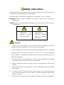
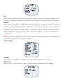
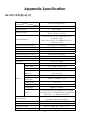
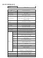
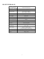
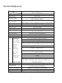
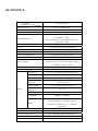
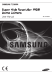
Day/ Night High-definition Color
Camera
User’s Manual
V 2.1.0
1
Thank you for purchasing our product. If there is any question or request,
please do not hesitate to contact dealer.
This manual is applicable to DS-2CC193P(N)-A(-C),
DS-2CC195P(N)-A(-C), DS-2CC191P(N)-A(-C), DS-2CC176P(N)-A(-C),
DS-2CC178P(N)-A(-C), DS-2CC573P-A, DS-2CC575P-A color cameras.
This manual may contain several technically incorrect places or printing
errors, and the content is subject to change without notice. The
updates will be added into the new version of this manual. We will
readily improve or update the products or procedures described in the
manual.
2
Safety Instruction
These instructions are intended to ensure that user can use the product
correctly to avoid danger or property loss.
The precaution measure is divided into “Warnings” and “Cautions”
Warnings: Serious injury or death may cause if any of the warnings is
neglected.
Cautions: Injury or equipment damage may cause if any of the cautions
is neglected.
Warnings Follow these Cautions Follow these
safeguards
to
precautions
to
prevent
serious
prevent potential
injury or death.
injury or material
damage.
Warnings
1. In the use of the product, you must be strict compliance with the
electrical safety regulations of the nation and region.
2. Input voltage should meet both the SELV(Safety Extra Low Voltage)
and the Limited Power Source with AC 24V or DC 12V according to
the IEC60950-1 standard. Please refer to technical specifications for
detail information.
3. Do not connect several devices to one power adapter as adapter
overload may cause over-heat or fire hazard.
4. Please make sure that the plug is firmly connected on the power
socket.
5.
When the product is mounted on wall or ceiling, the device shall be
firmly fixed.
6. If smoke, odor or noise rise from the device, turn off the power at
once and unplug the power cable, and then please contact the
service center.
7. If the product does not work properly, please contact your dealer or
3
the nearest service center. Never attempt to disassemble the
camera yourself. (We shall not assume any responsibility for
problems caused by unauthorized repair or maintenance.)
4
Cautions:
1. Make sure the power supply voltage is correct before using the
camera.
2. Do not drop the camera or subject it to physical shock.
3. Do not touch CCD (Charge Coupled Device) modules with fingers.
If cleaning is necessary, use clean cloth with a bit of ethanol and
wipe it gently. If the camera will not be used for an extended period,
please turn on the lens cap to protect the CCD from dirt.
4. Do not aim the camera at the sun or extra bright places. A
blooming or smear may occur otherwise (which is not a malfunction
however), and affecting the endurance of CCD at the same time.
5. The CCD may be burned out by a laser beam, so when any laser
equipment is on using, make sure that the surface of CCD will not be
exposed to the laser beam.
6. Do not place the camera in extremely hot, cold(the operating
temperature shall be-10℃~+60℃ ), dusty or damp locations, and
do not expose it to high electromagnetism radiation.
7. To avoid heat accumulation, good ventilation is required for
operating environment.
8. Keep the camera away from liquid while on using.
9. While on a delivery, the camera shall be packed in its original
packing, or packing of the same texture.
10. Regular part replacement: a few parts (e.g. electrolytic capacitor)
of the equipment shall be replaced regularly according to their
average enduring time. The average time varies because of
differences between operating environment and using history, so
regular checking is recommended for all the users. Please contact
with your dealer for more details.
5
Table of Contents
Chapter 1 Introduction ................................................................ 1
1.1 Product Features ................................................................... 2
1.2 Chief Introduction about Function ..................................... 2
1.3 Introduction of Box Camera Side Plate and Rear plate . 4
1.3.1 Introduction of Box Camera Side Plate ....................... 4
1.3.2 Introduction of Box Camera Auto IRIS Port.................. 5
1.4 Dome Camera Appearance .............................................. 6
1.5 IR Control ................................................................................ 7
Chapter 2 Installation .................................................................. 8
2.1 Box Camera Installation ....................................................... 9
2.2 Dome Camera Installation................................................. 11
Chapter 3 Menu Description..................................................... 13
3.1 Menu Interface .................................................................... 16
3.2 Menu Details ........................................................................ 17
3.2.1
Camera ID Settings ................................................... 17
3.2.2
Lens Type Settings ..................................................... 18
3.2.3
WB Settings ................................................................. 19
3.2.4
BLC Settings................................................................ 19
3.2.5
High Light Suppression.............................................. 20
6
3.2.6
D / N Settings ............................................................. 20
3.2.7
Shutter Settings .......................................................... 22
3.2.8
AGC Settings.............................................................. 22
3.2.9
Synchronization ......................................................... 22
3.2.10
Language................................................................. 23
3.2.11
Special Function...................................................... 23
3.2.12
Exit Setting ................................................................ 28
Appendix Specification............................................................. 29
DS-2CC193P(N)-A(-C) ............................................................... 29
DS-2CC195P(N)-A(-C) ............................................................... 30
DS-2CC191P(N)-A(-C) ............................................................... 31
DS-2CC178P(N)-A(-C) ............................................................... 32
DS-2CC176P(N)-A(-C) ............................................................... 33
DS-2CC573P-A............................................................................ 34
DS-2CC575P-A............................................................................ 35
7
Chapter 1 Introduction
1
1.1 Product Features
This series of the camera adopt high performance sensor and advanced print circuit
board design technology with high resolution, low distortion and low noise, etc. The key
features as following:
• Adopt high performance SONY CCD, and supply high definition and clear image
• Low illumination (Please refer to the specifications for details)
• Support ICR filter auto switch (Invalid for DS-2CC191P(N)-A(-C))
• Support high light suppression to get a clearer image in the vicinity of the strong light.
(Only DS-2CC176P(N)-A(-C) and DS-2CC178 P(N)-A (-C) available)
• Support OSD menu controlling, enable user to configure the detail parameters. (Invalid
for DS-2CC191 P(N)-A(-C))
• Adopt advanced stepping motor and sleep mode to avoid ICR oscillation. (Invalid for
DS-2CC191 P(N)-A(-C))
• Support BLC with programmable BLC area. (BLC area of DS-2CC191P(N)-A(-C) is
unconfigurable)
• Support auto white balance with high color rendition.
• High SNR give rise to clear and pleased image.
• Support auto electronic shutter control to adapt to different environments.
• Support auto gain control, adaptive brightness.
• Support auto iris.
• Support Privacy mask with 8 optional colors and 8 configurable areas. (Invalid for
DS-2CC191 P(N)-A(-C))
• Advanced design technology with high reliability.
• Advanced 3-axis mechanism design meet different mounting requirement by flexibly
adjusting the lens into the required angle (Only Dome camera support).
• Convenient back focus adjustment.
• Adopt advanced double-plate design to guarantee the CCD heat dissipation and
image quality.
1.2 Chief Introduction about Function
Motion Detection: In the surveillance area, the appearing motion object will trigger alarm.
User can select suitable sensitivity level with corresponding environment.
Privacy Mask: In the surveillance area, user can cover some place to protect other’s
privacy. The number of privacy mask area is up to 8.
2
Color B/W auto switch: The camera will display color image and become monochrome
automatically at night.
AGC: When object being shot look dim, please turn on AGC. It is propitious to enhance
brightness. To output standard video under different illumination, the range of auto gain
control must be large enough. When under low illumination, AGC will increase camera’s
sensitivity, and output bright and clear video.
S/N ratio: It is the ratio of Signal voltage and noise voltage. The ratio is larger, the effect of
noise is less, and the image is more spotless.
OSD (On Screen Display): The camera supports friendly menu interface on the screen, and
it’s convenient for user selecting expected function.
3-axis adjustment: Adopt advanced 3-axis mechanism design meet different mounting
requirement by flexibly adjusting the lens into the required angle.
Synchronous System: Synchronization usually contains power synchronization and
internal synchronization. Internal synchronization uses synchronous signal which is
generated by camera’s crystal oscillator to complete synchronous scan. Power
synchronization uses synchronous signal which is generated by camera’s adaptor to
complete synchronous scan.
White Balance: Because the camera could not adjust the color temperature according to
the light alteration as the eyes, that will cause color deviation. White balance is the white
rendition ability of the camera to adjust the problem according to the environment
automatically.
ICR Auto Switch: The filter will filter infrared light during the daytime and change to normal
filter at night to ensure a high sensitivity and clear image.
BLC: If there is glaring light in the background of the object being shot, the object will
look very dim. In this situation, turning on BLC function will make the object look bright and
clear, but the background scene will be overexposure.
3
BLC OFF
BLC ON
High light suppression: Distinguish glare point and take suppression effect automatically.
This function is in order to see the image around glare point more clearly.
1.3 Introduction of Box Camera Side Plate and Rear
plate
1.3.1 Introduction of Box Camera Side Plate
Figure 1.3.1 Box camera side plate
1. Back Focus Ring: When confirm the lens mounting, still don’t focalize, then need adjust
the back focus ring.
Adjusting Method: The back focus is adjusted on the optimal position, but for
compatible with different lens, should adjust back focus ring.
4
The steps are as below: firstly, tighten the lens, then loose the fixed back focus ring, and
rotate the lens till get clear image, lastly lock the back focus ring.
2. DD, VD Optional Switch
Auto Iris Video Drive: The camera inputs the video signal level into lens interior, and
internal drive circuit outputs control voltage to adjust lens aperture through electronic
motor;
Auto IRIS Direct Current Drive: The camera interior adds lens aperture electronic motor’s
drive circuit, and can directly output DC control voltage to control lens electronic
motor.
3. Menu Button: Press the middle menu button to call out menu, then press the up and
down to move the items, and left and right button to select items.
4. Fixed Bracket Fastness: Used for mounting bracket.
1.3.2 Introduction of Box Camera Auto IRIS Port
Figure 1.3.2 Definition of Auto IRIS Port
On the other side of the camera, there is an interface for auto iris, the type is negative
5
pattern four square holes, and the definition of pins is shown in the figure above. The
interface of video drive auto iris is using three pins, i.e. Power +, Video, GND; the interface
of direct drive auto iris is using four pins, i.e. damp+, damp-, drive+, drive-.
The description of box camera rear panel:
Fig 1.3.3 The rear panel of box camera
1.
Alarm OUT, IN, GND: support alarm in and out;
2. D/N: The switch of D/N mode via external trigger command;
3. RS-485: support RS-485 control, support connecting DVR, keyboard and etc to realize
remote control.
4. Video Output: output 540TVL super high resolution analog video;
5. Double power supply design: support 12VDC and 24VAC;
6. POWER: Power supply indicator, the LED light will turn on as the power supply is proper;
7. GROUND;
1.4 Dome Camera Appearance
Fig 1.4.1 Dome Camera Appearance
6
3-axis adjust: Pan Rotation Range: 0~355°, Tilt Rotation Range: 0~90°, support installation at
different angles.
1.5 IR Control
Note: This function is only valid for dome camera.
Fig 1.5.1 IR Remote
Menu: Press this button for 3 seconds to enter the camera main menu, and press “Menu” in
camera main menu to enter the sub menu interface.
Up: Move cursor upward.
Down: Move cursor downward.
Left: Move cursor leftward.
Right: Move cursor rightward.
Note: The other function keys are not available by now.
7
Chapter 2 Installation
8
Before mounting, please make sure that the device in the package is in good condition
and all the assembly parts are complete.
2.1 Box Camera Installation
Note: The lens weight must be less than the 1kg CS assembly. After installation the plane
the outshoot must be less than 5mm. When using the C assembly lens, please adopt C to
assemble the adapter.
There are two mounting methods for box camera: wall mounting, ceiling mounting, which
depends on the demand of the customers. Please stick to the following steps (take ceiling
mounting for example, wall mounting steps are the same).
1. Select the mounting method, and mount camera bracket according to the mounting
method. For cement wall, first you need to mount expansion screw (the mounting holes
of it needs to be the same with bracket), then mount the bracket, shown as figure 2.1.
For the woodiness wall, then skip the first step, and mount the bracket with self-tapping
screw. Please note that the mounting wall needs to sustain the weight 3 times heavier
than the sum weight of camera and bracket.
Figure 2.1 1 Install the mounting bracket
2. Mounting the camera. Screw the camera in the bracket by using the mount base at
the top of camera.
9
Fig. 2.1.2 Install the camera
3. Adjust the camera and move it to the monitoring point, and screw down the knob in
the bracket, fix the camera.
4. Screw the lens into the head of the camera, adjust the focus, and fasten the lens.
Fig. 2.1.3 Install the lens
Rear Panel Linkage of Box Camera:
10
Figure 2.1.4 Rear panel Linkage
2.2 Dome Camera Installation
Note: Take Vandal-Proof Dome camera for example:
1 . Loosen the set screws with a
hexagonal screw driver (attached
with the camera), and take down
the back box shown as below:
(No need for normal dome camera
to use hexagonal screw driver)
2. Use the screws to fix the
bottom board on the ceiling.
11
3. There is RCA analog
video
output
for
testing
and
MENU
buttons
for
configuration.
4. While viewing the video on
the
monitor,
adjust
the
camera’s view angle for your
need.
5. Tighten the set screws, and
install the back box.
12
Chapter 3 Menu Description
13
Note: The menu of DS-2CC176/178P(N)-A(-C) is as follow:
BLC SETUP
AREA
SET--VALUE
(3)- -| RETURN
Camera ID
-------------ABCDEFGHIJKLM
NOPQRSTUVWXYZ
0 1 2 34 56 7 8 9
: ! - +* ( ) /
<Cursor>
LOC- - RETURN
Menu
CAM ID
LENS
WB
BLC / HLS
D/ N
SHUTTER
AGC
SYNC
LANGUAGE
SPECIAL
EXIT
OFF
ALC--ATW1
HLS--AUTO1--OFF
--INT
EN
--SAVE
Specil Func
DETECT
OFF
FLC
OFF
BLEMISH DETECT
VIDEO
--PRIVACY
--RS485
--SYS INFO
--RETURN
Manual WB
Temp
RETURN
INC
AUTO D/N 1
VALUE (7)- - -|
D->N
3S
N->D
3S
IR SET
ON
RETUYN
AUTO D/N 2
D->N
N->D
RETUYN
BLC AREA
AREA
OK
RETURN
ALARM 1
TYPE
1
AREA
1*2*3*4
SENSIT (0)|- - - RETURN
ALARM 2
ON—>OFF
OFF—>ON
RETURN
SYS INFO
SOFT
HARD
DSP
RETURN
Privacy Mask
ZONE
(1)- ON/OFF
OFF
SET
OK
COLOR
(7)- MOSAIC
OFF
RETURN
Video Setup
GAMMA
0.45
ZOOM
--DNR
OFF
POS/NEG
POS
MIRROR
OFF
RES
HIGH
APERTURE (3)- - - Y
(4)- - - C
(4)- - - RETURN
ZOOM
RATE (01)|- LOC
RETURN
RS485 Setup
ADDRESS
000
PROTOCOL PELCO D
BAUDRATE
9600
RETURN
3S
3S
ELC Setup
VALUE L - - -| - - H
RETURN
ALC Setup
VALUE L - - -| - - H
RETURN
2
5
HLS Setup
LL Setup
V PHASE (000)---|--RETUYN
VALUE (3)- - -| - RETURN
Note: The menu of DS-2CC193/195P(N)-A(-C) is as follow:
14
BLC SETUP
BLC AREA
AREA
OK
RETURN
AREA
SET--VALUE
(3)- -| RETURN
ALARM 1
TYPE
1
AREA
1*2*3*4
SENSIT (0)|- - - RETURN
Camera ID
-------------ABCDEFGHIJKLM
NOPQRSTUVWXYZ
0 1 2 34 56 7 8 9
: ! - +* ( ) /
<Cursor>
LOC- - RETURN
Menu
CAM ID
LENS
WB
BLC
D/ N
SHUTTER
AGC
SYNC
LANGUAGE
SPECIAL
EXIT
OFF
ALC--ATW1
ON--AUTO1--OFF
--INT
EN
--SAVE
Privacy Mask
ZONE
(1)- ON/OFF
OFF
SET
OK
COLOR
(7)- MOSAIC
OFF
RETURN
Video Setup
GAMMA
0.45
ZOOM
--DNR
OFF
POS/NEG
POS
MIRROR
OFF
RES
HIGH
APERTURE (3)- - - Y
(4)- - - C
(4)- - - RETURN
Manual WB
INC
AUTO D/N 1
VALUE (7)- - -|
D->N
3S
N->D
3S
IR SET
ON
RETUYN
RS485 Setup
ADDRESS
000
PROTOCOL PELCO D
BAUDRATE
9600
RETURN
AUTO D/N 2
D->N
N->D
RETUYN
3S
3S
ELC Setup
VALUE L - - -| - - H
RETURN
ALC Setup
VALUE L - - -| - - H
RETURN
2
5
SYS INFO
SOFT
HARD
DSP
RETURN
Specil Func
DETECT
OFF
FLC
OFF
BLEMISH DETECT
VIDEO
--PRIVACY
--RS485
--SYS INFO
--RETURN
Temp
RETURN
ALARM 2
ON—>OFF
OFF—>ON
RETURN
LL Setup
V PHASE (000)---|--RETUYN
Note: The menu of DS-2CC573/575P-A is as follow:
15
ZOOM
RATE (01)|- LOC
RETURN
BLC SETUP
BLC AREA
AREA
OK
RETURN
AREA
SET--VALUE
(3)- -| RETURN
ALARM
TYPE
1
AREA
1*2*3*4
SENSIT (0)|- - - RETURN
Camera ID
-------------ABCDEFGHIJKLM
NOPQRSTUVWXYZ
0 1 2 34 56 7 8 9
: ! - +* ( ) /
<Cursor>
LOC- - RETURN
Menu
CAM ID
LENS
WB
BLC
D/ N
SHUTTER
AGC
SYNC
LANGUAGE
SPECIAL
EXIT
OFF
ALC--ATW1
ON--AUTO1--OFF
--INT
EN
--SAVE
SYS INFO
SOFT
HARD
DSP
RETURN
Specil Func
DETECT
OFF
FLC
OFF
BLEMISH DETECT
VIDEO
--PRIVACY
--RS485
--SYS INFO
--RETURN
Privacy Mask
ZONE
(1)- ON/OFF
OFF
SET
OK
COLOR
(7)- MOSAIC
OFF
RETURN
Video Setup
GAMMA
0.45
ZOOM
--DNR
OFF
POS/NEG
POS
MIRROR
OFF
RES
HIGH
APERTURE (3)- - - Y
(4)- - - C
(4)- - - RETURN
Manual WB
Temp
RETURN
INC
AUTO D/N
ZOOM
RATE (01)|- LOC
RETURN
VALUE (7)- - -|
D->N
3S
N->D
3S
IR SET
ON
RETUYN
ELC Setup
VALUE L - - -| - - H
RETURN
ALC Setup
VALUE L - - -| - - H
RETURN
LL Setup
V PHASE (000)---|--RETUYN
3.1 Menu Interface
Press menu button for about 2s, the OSD menu will show on the screen.
16
Press up/down button to move up/down cursor, left/right button to select the different
options;
Note:
HLS
(High
light
Suppression)
is
only
valid
for
DS-2CC176P(N)-A(-C)
and
DS-2CC178P(N)-A(-C).
3.2 Menu Details
Note: DS-2CC191P(N)-A(-C) does not support menu function.
3.2.1
Camera ID Settings
Press up/down to move cursor to “Camera ID”, press left/right to enable or disable this
setting.
Off: The camera ID will not display after exiting;
On: The camera ID will display after exiting;
Select On, and press confirm button to enter “Camera ID ” menu.
Press up/down to move the cursor to characters, numbers, symbols, and press confirm
button to modify the camera ID; move the cursor to <CURSOR>, press left/right to move it
to the characters of camera ID that needs modifying, press confirm button to change the
characters of camera ID to the blank; move the cursor to position setting, and press
confirm button to enter the camera ID position setting menu, then press up/down to
17
change the position of camera ID, press confirm button to exit the camera ID position
setting menu, and return to the camera ID menu; move the cursor to “RETURN” and press
confirm button to return to the previous menu.
3.2.2
Lens Type Settings
Press up/down to move the cursor to “LENS”, and press left/right to select the lens type as
ELC or ALC.
ELC adopts auto electronic shutter to adjust the brightness;
ALC adopts auto iris to control lens of camera adjustable;
Note: ELC: auto shutter, fixed iris;
ALC: auto iris, fixed shutter.
Select ELC and press confirm then the “ELC Setup” menu will show on the screen of the
monitor.
ELC Setup
VALUE
RETURN
L- - -| - - H
Press up/down to move the cursor to the “VALUE”, press left/right to adjust brightness,
move the cursor to “RETURN” and press confirm button to return to the previous menu.
Note: Different values indicate the different brightnesses.
Select ALC and press confirm then “ALC Setup” menu will show on the monitor:
Move the cursor to “VALUE”, press up/down to adjust the menu. After settings, move the
cursor to “RETUEN” and press confirm button to return to the previous menu.
18
3.2.3
WB Settings
Press the cursor to “WB”, then press left / right to select the item from ATW1, ATW2, Auto or
Manual.
ATW1: Camera recover color automatically according to the environment color
temperature, temperature range is approximate from 2500K to 6500K.
ATW2: Temperature range is approximate from 2500K to 15000K.
ATC: Adjust under steady color temperature environment. After selecting ATC, the white
balance will take effect to the current scene.
Manual: Adjust red and blue values to setup white balance.
Note: The AWB settings of DS-2CC176P-A/ DS-2CC178P-A include ATW1, ATW2, ATW3, and
MWB. The temperature range of ATW1 is about 3200-6500K, ATW2 is about 2200-9500K, and
ATW3 is about 2000-15000K.
Manual WB setting is as below:
Select “Manual…” and the menu will display on the screen:
Press up / down to “Temp”, and press left / right to adjust the value of temperature. After
settings, move the cursor to “RETURN” and press confirm button to return to the previous
menu.
3.2.4
BLC Settings
Press up / down to “BLC”, and press left / right to select “OFF” or “ON---”. Selecting “ON---”
and the menu will display on the screen:
19
Move cursor to “AREA”, and press left / right to set the BLC area as up, down, left, right,
middle or manual, then the BLC area is on the screen:
BLC area’s setting step is as following:
Move cursor to “SET…”, and press “enter” to confirm and go to the submenu:
Move cursor to “AREA”, and press “enter” to select “OFF”, “LOC” or area size;
Press enter to confirm the location, and press up / down to set the area’s location;
Press enter to confirm the area size, and press up / down to set BLC area’s size.
After settings, move the cursor to “RETURN” and press confirm button to return to the
previous menu.
Note: When “AREA” is not “OK”, press up / down/ left / right not to move cursor.
3.2.5
High Light Suppression
Note: only valid for DS-2CC176/178P(N)-A(-C).
Press up / down to select “BLC/ HLS”, and use left / right to select high light suppression.
Press enter to open HLS function which can detect and suppress high light point
automatically, in order to get a clearer image.
HLS values setting:
Press left/ right to adjust the value.
Note: Different values indicate various suppression degrees.
3.2.6
D / N Settings
Press up /down to move the cursor to “D / N”, and press left / right to select item from Day,
Night, Auto1, Auto2.
20
Auto1 Setting:
Select Auto1 and press “enter” to go into the submenu:
Press up / down to move the cursor to “VALUE”, and press left / right to select value from 0
to 7;
Move cursor to D->N, and press left / right to select the switch time including 3S, 5S, 10S, 15S,
20S, 25S or 30S.
Move cursor to N->D, and press left / right to select the switch time including 3S, 5S, 10S, 15S,
20S, 25S or 30S.
After settings, move the cursor to “RETURN” and press confirm button to return to the
previous menu.
Press up / down to move the cursor to “IR SET”, and press left / right to select ON or OFF;
Note: When “IR SET” is “ON”, the camera turns on the ICR stabilization function. If the
camera turns to Night mode 5 times in 10 minutes, the camera will go to protection mode.
In this mode, camera will keep Black/White for at least 1 hour until the environment is bright
enough.
Note: Auto1 means auto switch from Day to Night. And value from 0 to 7 means switching
threshold, the value is more, the corresponding environment is darker. And “D->N 3s”
means when the light condition is up to the switching threshold, and 3s later the camera
turns Day to Night. And “N->D 3s” is the same as “D->N 3s”.
Auto2 Setting: It is the same as the Auto1 except lack of VALUE.
Note: Auto2 means external trigger switch. There is a D / N port which is once grounding
and will trigger switch from Day to Night.
Note: For dome camera, settings are: “Auto…”, “Day” and “Night”. The menu is as follow,
and the operations are the same as above.
21
3.2.7
Shutter Settings
Move cursor to “Shutter” through pressing up / down.
When lens is ALC, press “enter” to select shutter speed: OFF, 1/120, 1/250, 1/500, 1/750,
1/1K, 1/2K, 1/4K, 1/10K, 1/100K, Auto × 2, Auto × 4, Auto × 6, Auto × 8, Auto × 12, Auto × 16,
Auto × 24, Auto × 32, Auto × 48, Auto × 64, Auto × 96, Auto × 128, Auto×160, Auto × 256.
When lens is ELC, press “enter” to select shutter speed: Auto, Auto × 2, Auto × 4, Auto × 6,
Auto × 8, Auto × 12, Auto × 16, Auto × 24, Auto × 32, Auto × 48, Auto × 64, Auto × 96, Auto ×
128, Auto ×160, and Auto × 256.
Note: Auto × 2, Auto × 4 and so on mean sense up function realized through adding
exposure time.
3.2.8
AGC Settings
When selecting Day or Night mode, “AGC” enables including HIGH, MID, LOW and OFF
items; while selecting Auto1 mode, “AGC” disables.
When “sense up” enables, “AGC” becomes “MOTION” which includes five modes:
SLOWER, SLOW, STD, FAST, FASTER. The camera will automatic calculate to select sense up
or AGC to promote brightness of image according to the speed of object.
3.2.9
Synchronization
Support internal and line lock synchronization. When using DC12V power supply, it displays
internal synchronization and is not adjustable. When using AC24V, user can select internal
or line lock synchronization.
22
3.2.10
Language
Move cursor to “CN / EN” through up / down, and press left / right to select CN or EN.
3.2.11
Special Function
Move cursor to “Special”, press “enter” and the menu will appear on the screen.
Motion Detection
Note: MODE1 has twinkled motion detection pane, and can trigger alarm output;
MODE2 can only trigger alarm output without twinkled motion detection pane.
Move cursor to “Motion Detection”, and press left / right to select motion detection mode:
OFF, MODE1 or MODE2.
MODE1 Setting:
Move cursor to MODE1, press “enter” and the menu will appear on the screen:
Press up/down to select “Type 1”, and move cursor to “AREA”, and press left / right to
select from 4 areas; move cursor to “SENSIT”, and press left / right to select sensitivity value
from 0 to 7. After settings, move the cursor to “RETURN” and press confirm button to return
to the previous menu.
Press up/down to select “Type 2”, the area setting is not available now. Move cursor to
“SENSIT”, and press left/right to select sensitivity value from 0 to 7. After settings, move the
23
cursor to “RETURN” and press confirm button to return to the previous menu.
Press up/down to select “Type 3”, and move cursor to “AREA”. Press left/right to select
“Default” or “SET…”. If “Default” is selected, press “Enter” to display the default areas and
press “Enter” again to exit. If “SET…” is selected, press “Enter” and up/down/right/left to
select areas, and then press “Enter” on the selected area to choose or hide the area.
Move the cursor to “RETURN” and press confirm button to exit.
Note: Type 1: Has 4 adjustable windows;
Type 2: Full screen;
Type 3: Default 12 × 8 windows on full screen, pressing “enter” button can cancel a
window.
MODE2 Setting:
Move cursor to MODE2, press “enter” and the menu will appear on the screen:
Move cursor to ON->OFF, press left / right to set the responding time from ON to OFF:0, 2, 5,
10, 15, 20, 25, 30 (unit: s); And press left / right to set the responding time from OFF to ON;
After settings, move the cursor to “Return” and press confirm button to return to the
previous menu.
Note: ON->OFF means the alarm will be triggered when motion detection duration is
longer than 2s;
OFF->ON means the alarm will continue for 5s when motion detection stops.
24
Fig 3.2.1
Fig 3.2.2
Fig 3.2.3
Note: For dome camera, motion detection settings are: On and Off; select “On” to enter
motion detection interface as follow, the operations are the same as above.
25
FLC
Move cursor to flicker proof function, and press “enter” to set on or off. This function is used
for PAL standard camera under 60Hz light source, and NTSC standard camera under 50Hz.
BLEMISH
After used a long time, Charge Coupled Device(CCD) will appear blemish, and this
camera possess Blemish Detection Function to solve this problem. Move cursor to
“BLEMISH”, press “enter”, and the “DETECT” will become “WAIT” while this camera enables
blemish detection function. When “WAIT” becomes “DETECT”, the auto modification is
completed.
Note: This function will be more active in the absolutely dark environment. Make sure that
close the lens’s IRIS before using this function.
VIDEO Setting
GAMMA
Move cursor to “GAMMA”, and press left / right to set GAMMA value 0.45 or 1.
Digital Zoom
Move cursor to “ZOOM”, press “enter”, and the menu will appear on the screen:
26
The zoom rate is selectable from 01 to 16.Ater zoom, seleting “LOC”, press up / down / left /
reght to control the image moving. After setting, press“RETURN” to RETURN previous menu.
DNR
User can set turn on or off the digital noise reduction.
POS/ NEG
Move cursor to “POS / NEG”, and press left / right to select POS or NEG. Selecting POS, the
video will be normal, while selecting NEG, the video will be negative.
MIRROR
There are horizontal, vertical, middle and OFF in this function.
RESOLUTION
Move cursor to“RESOLUTION”, presss left / right to select high, middle or low to adjust
video’s resolution.
APERTURE
Move cursor to “APERTURE”, and press left / right to set the aperture value from 0 to 7.
Y
Means brightness is adjustable from 0 to 7.
C
Means saturation is adjustable from 0 to 7.
PRIVACY
Move cursor to “PRIVACY”, press “enter” and the menu will appear on the screen:
Move cursor to “ZONE” to select the number of privacy mask. And there are 8 zones in
total. Move cursor to “ON / OFF”, and press left / right to select ON. Move cursor to “SET”,
and press “enter” to edit mask and size as a->c order:
a. Select “LOC”, and move the gray (optional color) quadrate area to expected position,
then press “enter”.
b. Select “AREA”, and press up / down / left / right to control the size of mask area.
c. Repeat above operation to set other mask area.
Move the cursor to “COLOR”, there are 8 colors can be selected.
After settings, move the cursor to “Return” and press confirm button to return to the
27
previous menu.
RS485
Set protocol, baud rate and address before use RS-485 to control camera. Move cursor to
“RS485”, press “enter”, and the menu will appear on the screen.
Note: This function is invalid for dome camera.
Address
Move cursor to “Address”, press left/ right to set the number (optional from 0 to 254).
Protocol
Move cursor to “PROTOCOL”, and press “enter” to select PELCO-P or PELCO-D.
Note: Controller must set corresponding protocol and baud rate with camera to control
the camera.
Baud Rate
Move cursor to “BAUDRATE”, and press “enter” to select baud rate from 1200, 4800, 9600,
19200 (bps).
SYSTERM INFORMATION
Press “enter” to check the hardware, software and DSP information. And this information
is established for maintenance or modification in the future. After settings, move the cursor
to “Return” and press confirm button to return to the previous menu.
3.2.12
Exit Setting
Move cursor to “EXIT”, and press left / right to select the way of exit from SAVE, CANCEL
and DEFAULT.Then press “enter” to exit the menu.
CANCEL: Press “enter” to cancel the setting parameter and exit the menu.
SAVE: Press “enter” to save the setting parameter and exit the menu.
DEFAULT: Press “enter” to restore the factory default value and exit the menu.
28
Appendix Specification
DS-2CC193P(N)-A(-C)
Model
DS-2CC193P(N)-A(-C)
Parameter
Image Sensor
1/3 inch SONY CCD
Signal System
PAL / NTSC
Effective Pixels
PAL: 752 (H) × 582 (V)
NTSC: 768 (H) × 494 (V)
Min. Illumination
Color :0.1Lux @ F1.2, 0.0003Lux @ (F1.2,
sensitivity × 256)
B/W: 0.01Lux @ F1.2, 0.00003Lux @ (F1.2,
sensitivity × 256)
Electronic Shutter Speed
1/50(1/60)s to 1/100,000s
Lens Mount
C / CS mount
Auto Iris Lens
DC / Video Drive
Day & Night
IR Cut Filter Auto Switch
Horizontal Resolution (TVL)
Synchronization
Video Output
540 (Color), 600 (B/W)
Internal / Power synchronization
1Vp-p Composite Output (75Ω/BNC)
S/N Ratio
More than 50dB
Camera ID
On / Off (15 letters, adjusted position)
Auto Gain
Low / Middle / High / Off
D / N Mode
Auto1 / Auto2 / Day / Night
Auto White
Balance
Auto trace WB1/ Auto trace WB2 / Manual /
Auto Control
Private Mask
Menu
On / Off, Maximum 8 Zones
Motion
Detection
Mode 1 / Mode 2 / Off
Flicker Proof
RS-485
On / Off
Address / Protocol / Baud Rate
Language
Video
Power Supply
English / Chinese
Gamma Amendment, Digital Zoom, Digital
Noise Reduction, POS/NEG ,Mirror, Resolution,
Sharpness, Y, C, Blemish Detection
24VAC / 20VA ±10%, 12VDC / 300Ma ±10%
(-C) series support 100-240VAC
Working Temperature
-10℃ ~ 60℃(14°F ~ 140°F)
Power Consumption
5W (10W MAX With ICR Working)
Dimension (mm)
68 × 57 × 144.8 (2.7” × 2.2” × 5.7”)
Weight
500g (1.1lbs)
29
DS-2CC195P(N)-A(-C)
Weight
500g (1.1lbs)
Model
Parameter
DS-2CC195P(N)-A(-C)
Image Sensor
1/3 inch SONY CCD
Signal System
PAL / NTSC
Effective Pixels
PAL: 752 (H) × 582 (V)
NTSC: 768 (H) × 494 (V)
Min. Illumination
Electronic Shutter
Speed
Lens Mount
1/50(1/60)s to 1/100,000s
C / CS mount
Auto Iris Lens
Day / Night
DC / Video Drive
IR Cut Filter Auto Switch
Horizontal Resolution
(TVL)
Synchronization
Video Output
S / N Ratio
540 (Color), 600 (B/W)
Internal / Power synchronization
1Vp-p Composite Output (75Ω/BNC)
More than 50dB
Camera ID
On / Off (15 letters, adjusted position)
Auto Gain
Low / Middle / High / Off
D/N
Mode
White
Balance
Private
Mask
Menu
Color: 0.02Lux @ F1.2, 0.00012Lux @ (F1.2,
sensitivity × 256)
B/W :0.002Lux @ F1.2, 0.000007Lux @ (F1.2,
sensitivity × 256)
Motion
Detection
Auto1 / Auto2 / Day / Night
Auto trace WB1/ Auto trace WB2 / Manual /
Auto Control
On / Off, Maximum 8 Zones
Mode 1 / Mode 2 / Off
Flicker
Proof
On / Off
RS-485
Address / Protocol / Baud Rate
Language
Video
Power Supply
Working Temperature
English / Chinese
Gamma Amendment, Digital Zoom, Digital
Noise Reduction, POS/NEG ,Mirror, Resolution,
Sharpness, Y, C, Blemish Detection
24VAC / 20VA ±10%, 12VDC / 300Ma ±10%
(-C) series support 100-240VAC
30-10℃ ~ 60℃(14°F ~ 140°F)
Power Consumption
5W (10W MAX With ICR Working)
Dimension (mm)
68 × 57 × 144.8 (2.7” × 2.2” × 5.7”)
DS-2CC191P(N)-A(-C)
Model
Parameter
DS-2CC191P(N)-A(-C)
Image Sensor
1/3 inch SONY CCD
Signal System
PAL / NTSC
Effective Pixels
PAL: 752 (H) × 582 (V)
NTSC: 768 (H) × 494 (V)
Min. Illumination
Electronic Shutter
0.05Lux @ F1.2
1/50(1/60)s to 1/100,000s
Day & Night
Electronic
Auto Iris Lens
DC / Video
Lens Mount
C / CS mount
Horizontal Resolution
Synchronization
Video Output
540TVL
Internal / Power synchronization
1Vpp Composite Output
S/N Ratio
More than 50 dB
BLC
ON / OFF
Working
Temperature
Power Supply
-10℃ ~ 60℃
24VAC / 12VDC, ±10%
(-C) series support 100-240VAC
Power Consumption
Dimension (mm)
3W MAX
68 × 57 × 144.8 (2.7” × 2.2” × 5.7”)
Weight
500g (1.1lbs)
31
DS-2CC178P(N)-A(-C)
Model
Parameter
DS-2CC178P(N)-A(-C)
Image Sensor
1/3"SONY CCD
Signal System
PAL / NTSC
Effective Pixels
PAL: 752 (H) × 582 (V)
NTSC: 768 (H) × 494 (V)
Min. Illumination
Electronic Shutter
Color: 0.1Lux @ F1.2, 0.0003Lux @ (F1.2, sensitivity×256)
B/W: 0.01Lux @ F1.2, 0.00003Lux @ (F1.2, sensitivity×256)
1/50(1/60)s to 1/100,000s
Lens Mount
C/CS Mount
Auto Iris Lens
Day / Night
DC/Video Drive
IR Cut Filter Auto Switch
Horizontal Resolution
(TVL)
Synchronization
Video Output
540 (Color), 600 (B/W)
Internal / Power synchronization
1Vp-p Composite Output (75Ω/BNC)
S/N Ratio
Camera ID
On / Off (15 letters, adjusted position)
Auto Gain
Low / Middle / High / Off
D / N Mode
Auto White
Balance
Privacy
Menu
More than 50dB
Motion
Detection
BLC / HLC
RS-485
Auto1 / Auto2 / Day / Night
Auto trace WB1/ Auto trace WB2 / Manual / Auto Control
On / Off, Maximum 8 Zones
Mode 1 / Mode 2 / Off
BLC:Area / Intensity / Off
HLC:Intensity Setting
Address / Protocol / Baud Rate
Flicker Proof
On/Off
Language
Video
Setting
Chinese/English
Gamma Amendment, Digital Zoom, Digital Noise Reduction,
POS/NEG ,Mirror, Resolution, Aperture, Y, C, Blemish
Detection
Working Temperature
Power Supply
Power Consumption
-10℃~60℃
AC24V±10% / DC12V±10%
(-C) series support 100-240VAC
5W MAX (10W MAX with ICR working)
Dimension (mm)
144.8×68×57
Weight
500g
32
DS-2CC176P(N)-A(-C)
Model
Parameter
DS-2CC176P(N)-A(-C)
Image Sensor
1/2"SONY EXview HAD CCD
Signal System
PAL / NTSC
Effective Pixels
PAL: 752 (H) × 582 (V)
NTSC: 768 (H) × 494 (V)
Min. Illumination
Electronic Shutter
Color: 0.003Lux @ F1.2, 0.00002Lux @ (F1.2, sensitivity×256)
B/W: 0.0003Lux @ F1.2, 0.000002Lux @ (F1.2, sensitivity×256)
1/50(1/60)s to 1/100,000s
Lens Mount
C/CS Mount
Auto Iris Lens
Day / Night
DC/Video Drive
IR Cut Filter Auto Switch
Horizontal Resolution
(TVL)
Synchronization
Video Output
540 (Color), 600 (B/W)
Internal / Power synchronization
1Vp-p Composite Output (75Ω/BNC)
S/N Ratio
Camera ID
On / Off (15 letters, adjusted position)
Auto Gain
Low / Middle / High / Off
D / N Mode
Auto
White
Balance
Privacy
Men
u
More than 52dB
Motion
Detection
BLC / HLS
RS-485
Auto1 / Auto2 / Day / Night
Auto trace WB1/ Auto trace WB2 / Manual / Auto Control
On / Off, Maximum 8 Zones
Mode 1 / Mode 2 / Off
BLC:Area / Intensity / Off
HLS:Intensity Setting
Address / Protocol / Baud Rate
Flicker Proof
On/Off
Language
Video Setting
Chinese/English
Gamma Amendment, Digital Zoom, Digital Noise
Reduction, POS/NEG ,Mirror, Resolution, Aperture, Y, C,
Blemish Detection
Working Temperature
Power Supply
Power Consumption
-10℃~60℃
AC24V±10% / DC12V±10%
(-C) series support 100-240VAC
5W MAX (10 W MAX with ICR working)
Dimension (mm)
68×57×144.8
Weight
500g
33
DS-2CC573P-A
Model
DS-2CC573P-A
Parameter
Image Sensor
1/3 inch SONY CCD
Signal System
PAL
Effective Pixels
752 (H) × 582 (V)
Min. Illumination
Color: 0.1Lux @ F1.2, 0.0003Lux @ (F1.2,
sensitivity × 256)
B/W: 0.01Lux @ F1.2, 0.00003Lux @ (F1.2,
sensitivity × 256)
Electronic Shutter
Lens
1/50s to 1/100,000s
2.8~11mm (2.5~6mm optional)
Auto IRIS
DC drive
Day / Night
IR cut filter with auto switch
Horizontal Resolution
540TVL(Color), 600TVL (B/W)
Synchronization
Video Output
Internal / Power synchronization
1Vp-p Composite Output (75Ω/BNC); Test
Monitor OUT [ 1Vp-p Composite Output
(75Ω/BNC), Device Line]
S/N Ratio
More than 50dB
Adjustment Range
Pan 0~180°, Tilt 0~80°, Rotation 0~80°
Camera ID
On / Off (15 letters, adjusted position)
Auto Gain
Low / Middle / High / Off
D / N Mode
Auto / Day / Night
Auto White
Balance
Auto trace WB1/ Auto trace WB2 / Manual /
Auto Control
Private Mask
Menu
On / Off, Maximum 8 Zones
Motion
Detection
ON / Off
Anti-flicker
On / Off
Language
English / Chinese
Video
Power Supply
Gamma Amendment, Digital Zoom, Digital
Noise Reduction, POS/NEG ,Mirror,
Resolution, Sharpness, Y, C, Blemish
Detection
24VAC / 20VA ±10%, 12VDC / 300Ma ±10%
Working Temperature
-10℃ ~ 60℃(14°F ~ 140°F)
Power Consumption
4W (10W MAX With ICR Working)
Dimension
φ115.93mm×112.7mm
Weight
180g
34
DS-2CC575P-A
Model
DS-2CC575P-A
Parameter
Image Sensor
1/3 inch SONY CCD
Signal System
PAL
Effective Pixels
752 (H) × 582 (V)
Min. Illumination
Color :0.02Lux @ F1.2, 0.00012Lux @ (F1.2,
sensitivity × 256)
B/W :0.002Lux @ F1.2, 0.000007Lux @ (F1.2,
sensitivity × 256)
Electronic Shutter
Lens
1/50s to 1/100,000s
2.8~11mm (2.5~6mm optional)
Auto IRIS
DC drive
Day / Night
IR cut filter with auto switch
Horizontal Resolution
Synchronization
Video Output
540 TVL (Color), 600 TVL (B/W)
Internal / Power synchronization
1Vp-p Composite Output (75Ω/BNC); Test
Monitor OUT [ 1Vp-p Composite Output
(75Ω/BNC), Device Line]
S/N Ratio
More than 50dB
Adjustment Range
Pan 0~180°, Tilt 0~80°, Rotation 0~80°
Camera ID
On / Off (15 letters, adjusted position)
Auto Gain
Low / Middle / High / Off
D / N Mode
Auto / Day / Night
Auto White
Balance
Auto trace WB1/ Auto trace WB2 / Manual /
Auto Control
Private Mask
Menu
On / Off, Maximum 8 Zones
Motion
Detection
ON / Off
Anti-flicker
On / Off
Language
English / Chinese
Video
Power Supply
Gamma Amendment, Digital Zoom, Digital
Noise Reduction, POS/NEG ,Mirror,
Resolution, Sharpness, Y, C, Blemish
Detection
24VAC / 20VA ±10%, 12VDC / 300Ma ±10%
Working Temperature
-10℃ ~ 60℃(14°F ~ 140°F)
Power Consumption
4W (10W MAX With ICR Working)
Dimension
φ115.93mm×112.7mm
Weight
180g
35
First Choice for Security Professionals
36