1
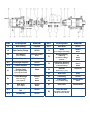
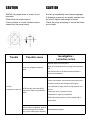
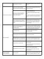
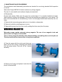
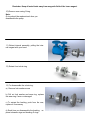
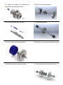
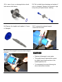
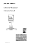
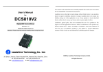
WMTA6 LN SERIES SEAL-LESS MAG-DRIVE MULTI-STAGE
TURBINE PUMPS
INSTALLATION, OPERATION, AND MAINTENANCE INSTRUCTIONS
TO OBTAIN THE BEST PERFORMANCE FROM YOUR WARRENDER WMTA6 LN
PUMP, PLEASE READ THIS MANUAL CAREFULLY.
Failure to follow the recommended procedures may result in early and severe
damage to your WARRENDER pump, and may also invalidate the guarantee.
Thank you for your purchase of a WARRENDER WMTA6 LN Series Multi-Stage turbine pump.
Proper installation and maintenance will provide many years of trouble free operation.
REF
Description
Material
REF
Description
Material
10
Rear Casing
Titanium
65.3
Stud Nuts
SS316
15
Rear Casing Flange
SS316
70
Shaft
SS431
(incl. of keys and circlip)
SS316
Ext. Magnet
Neodym./Steel
(incl. of screw)
Steel
30
Int. Magnet
SS316/CoSm
40.1
Centrifugal Impeller
SS316
40.2
Turbine Impeller
SS316
O-rings (a+b)
Viton
20
51
a) O-ring 6437 (348)
b) O.ring 6512 (354)
Thrust Bearings
Carbon
(incl. of o-ring)
(incl. of pins)
Viton
SS316
62
Rear Ring
SS316
(incl. of pin)
SS316
65.1
Centrifugal Impeller
Nut
SS316
Lockwasher
SS316
61
65.2
Sleeve Bearing
75
76
78
d) Bearing
e) Tolerance Rings
f) Screw
SiC
SS316
SS316
Stationary Bushing
f) Stationary Bushing
e) Tolerance Ring
Carbon
SS316
Bracket
Cast Iron
(9-8½-1⅛_1⅜_1⅝)
82
Rear Foot
Steel
84
Front Ring
SS316
Pump Head
Carbon Steel
(incl. of drain plug)
Steele
86
End Cover
Carbon Steel
88
(10+30+40.1+40.2+51+61+
62+65.2+70+75+76+84)
85
Rear Wet End
1. SAFETY
INSTALLATION, OPERATION AND MAINTENANCE MUST BE DONE BY QUALIFIED PERSONNEL IN STRICT ACCORDANCE WITH THIS MANUAL AND MUST COMPLY WITH ALL LOCAL,
STATE AND FEDERAL CODES.
For your protection and the protection of others, always follow the safety rules outlined in this booklet.
Observe warning signs on machines and act accordingly. Form safe work habits by reading the rules
and abiding by them.
Keep this booklet handy and review it from time to time to refresh your understanding of the rules.
The use of the word “DANGER” always signifies an immediate hazard with a high likelihood of
severe personal injury or death if instructions, including recommended precautions, are not followed.
The use of the word “WARNING” signifies the presence of hazards or unsafe practices that could
result in severe personal injury or death if instructions, including recommended precautions, are not
followed.
The use of the word “CAUTION” signifies possible hazards or unsafe practices that could result in
minor injury, product or property damage if instructions, when recommended precautions are not
followed.
SDTM series are magnetic driven pumps. The use of the word “Magnetic” indicates the persistent
presence of a magnetic field.
Such fields present immediate danger to individuals having electronic medical devices,
metallic heart valves, metallic prosthetics or metallic surgical clips.
2. INSPECTION
All Warrender pumps are inspected prior to shipping and prepared for safe transportation.
Upon receipt of the WMTA6 LN series pump, check for any damage that may have occurred during
shipment.
Notify the courier and Warrender Ltd. Pumps promptly if damage has occurred.
3. STORAGE
If the pump is not installed immediately, it should be protected from exposure to moisture and dust.
Shipping protections on the ports installed at the factory, must be kept securely in place.
Storage instruction provided by the driver manufacturer should be observed.
4. INSTALLATION
1. The foundation should be substantial in order to reduce vibrations, and rigid enough to prevent
flexing that can result in misalignment.
Foundation bolts of the correct size should be installed by referring to certified drawings if the
baseplate is supplied with the pump.
2. The pump must be mounted horizontally on a level foundation, with the discharge port facing upwards.
3. When installing a close-coupled motor-pump unit without baseplate level the pump base accurately, using shims under the pump feet. The pump must sit firmly and evenly on its foundation. It
must not be distorted by bolting to an uneven surface.
4. Bare frame motor-pump unit on baseplate, level the baseplate accurately, using shims under the
baseplate next to the foundation bolts. The baseplate must sit firmly and evenly on its foundation: it
must not be distorted by bolting to an uneven surface, that will throw the pump and motor out of
alignment.
5. OPERATION SAFETY BASICS
Listed below are some of basics you should keep in mind in addition to company rules regarding installation, operation and maintenance:
NEVER: start pump without proper prime (casing must be full of liquid)
NEVER: operate pump with the suction or the discharge valve closed.
NEVER: run pump dry over a few minutes.
NEVER: operate pump if there are signs of leakage.
NEVER: change pump service condition without approval of your Warrender Pump representative.
NEVER: loosen port connection while system is under pressure.
NEVER: attempt to clean the pump while it is operating.
NEVER: operate pump above rated temperature and pressure.
NEVER: Pump liquids containing ferromagnetic particles of any size, or substances that will erode or
chemically attack the internal parts of the pump. If in doubt, please contact your pump supplier for
advice.
NEVER: Restrict both the inlet and the discharge lines while the pump is running. Restriction of the
inlet may cause the pump to cavitate, leading to loss of efficiency and rapid wear.
Reduced flow can be obtained if required by a valve branch from the discharge side of the pump
back to the liquid source.
If the pump is to be shutdown for an extended period, circulate clean water (or other suitable solvent
compatible with pump materials) for several minutes, to avoid the risk of internal precipitation or
encrustation.
6. PUMP IDENTIFICATION
Every Warrender pump unit has a nameplate located on the side of the casing. It is recommended
that the purchaser record the serial number and reference it when requesting information or service
parts from Warrender Ltd. The serial number, must be used for all correspondence and spare parts
order.
7. SUCTION AND DISCHARGE PIPING
- Piping should be supported independently of the pump and the line up naturally to pump ports.
Suction piping should be installed with as few restrictions as possible to provide no less than
minimum NPSH as listed on the specification sheet.
- The length of the suction pipe should be kept to a minimum.
- Suction line should be clean and/or a strainer should be installed to protect the impeller from
damage by welding slag, mill scale, or other foreign particles during initial start-up.
- Pump suction use only a full flow valve.
- Pressure gauges should be installed in both the suction and discharge piping.
The gauges will enable the operator to easily observe the operation of the pump, and to control if the
pump is operating in conformance with the duty point required.
If cavitation or other unstable operation should occur, widely fluctuating pressure will be noted.
8. ELECTRICAL DANGER WARNING
Only a qualified electrician should make the electrical connections to the pump drive motor.
Thoroughly read motor manufacturers instructions before installation.
Check motor nameplate data to be certain that all wiring, switches, starter, and overload
protection are correctly sized.
Install the motor according to local electrical codes.
Check all connections to the motor and starting device with wiring diagram. Check voltage, phase,
and frequency on motor nameplate with line circuit.
NOTE: Install a flexible electrical conduit on the motor to allow movement of at least 12 inches.
This is necessary to service and inspect the pump.
9. PUMP SPEED
WMTA6 LN pumps are designed to rotate at speeds up to 4000 RPM.
Standard speeds are:
ELECTRIC
MOTOR
50Hz
60Hz
2POLES
2900RPM
3500RPM
4POLES
1450RPM
1750RPM
If the pump is driven at variable speeds via an a.c. frequency inverter, keep within the recommended
limit of speed.
10. STARTING
Fully open the suction valve. Pump requires a flooded suction.
Do not operate pump with suction or discharge valve closed. Operating pump more than a
few minutes with the suction valve closed can cause bearing failure.
CAUTION
CAUTION
WMTA6 LN pumps sense of rotation is not
reversible.
At start-up immediately check pressure gauges.
Check driver for proper rotation.
If discharge pressure is not quickly reached stop
the motor, reprime and attempt to restart.
Correct rotation is counter clockwise when
viewed from the pump casing.
Check the pump and piping to ensure that there
are no leaks.
Trouble
Possible cause
Investigative /
corrective action
Bleed all vapor or air from port 6.
Pump not completely filled with
liquid
Allow more cool down time if pumping low temperature
fluid.
Check suction line for air leak if suction pressure is
lower than atmospheric.
Suction line blocked—check suction screen and valve.
Excessive pressure drop through suction piping.
No Flow,
No pressure at start up.
NPSH actually lower than NPSH
requirement listed on specification
sheet.
Flow restricted by vapor pockets in high points of suction line.
Suction tank level or pressure too low.
Entrained air or vapor in pumped fluid.
NPSH reduced by presence of more volatile fluid in
process fluid.
Failure of drive component, such as
interconnecting shaft or impeller
Disassemble and inspect
key, or item missing from assembly.
Reverse direction of rotation.
Note: Impeller and driver rotate in the same
direction.
NPSH actually lower than NPSH
Refer to solutions listed under “No Flow, no
requirement listed on specification sheet. pressure at start-up”
Increase through-flow rate.
Insufficient flow or head-rise.
Motor Overloaded.
Flow too low, causing overheating of
fluid resulting in internal boiling or
unstable pump operation.
By pass part of pump discharge to supply
tank.
Use seal cavity bypass and vent the high point
of pump to continuously increase inlet flow
rate.
Diffuser discharge partially plugged or
impeller damaged by passage of solid
particle.
Clean these areas of all obstructions and
restore surfaces to a smooth polished finish
( use emory cloth or machine), free of all
corrosion pitting.
Process fluid specific gravity or viscosity
different from values shown on
specification sheet.
Check actual viscosity and specific gravity at
operating temperature. Viscosity higher than
ten centipoises will cause reduced head and
flow with increased power consumption
Drive speed too low.
Check speed against value listed on
specification sheet.
Pressure gauges of flow meters in error.
Calibrate instrumentation
Fluid specific gravity or viscosity higher
Check actual viscosity and specific gravity
than values listed on specification sheet. against value listed on specification sheet.
Check circuit breaker heater size and setting.
Electrical failure in electric driver.
Check Voltage
Current for each phase should be balanced
within three percent
Remove driver and check for freedom of
rotation of pump shaft assemblies
Mechanical failure in driver, or pump.
Remove fluid end and search for any mechanical failure
Excessive discharge
pressure pulsations
Insufficient NPSH.
Refer to solution for insufficient NPSH under
“No Flow, no pressure at start-up.” above.
11. MAINTENANCE AND DISASSEMBLY
The maintenance and disassembly procedure are intended for use during standard field inspection
or service.
Warrender Pumps WMTA6 LN series contains very strong magnets.
The use of a non metallic work surface is highly recommended.
A) Disassembly
Proceed with caution. Make sure the pump has cooled down if it is recently handled hot liquids.
Wear protective clothing and eyewear if the pump has handled any dangerous or toxic liquids. The
back to the manufacturer for reconditioning, it must be thoroughly drained and cleaned by the customer.
1) Remove bolts connecting pump and motor to foundation or base plate.
2) Remove hex bolts connecting pump to motor.
3) Separate the pump from the motor end by pulling the driver away from the pump.
WARNING MAGNETIC
Warrender pumps contain extremely strong magnets. The use of non magnetic tools and
work surface are highly recommended.
There is strong magnetic attraction when disassembling / assembling drive end to liquid end.
The shop area must be clean and free of any ferrous particles.
4) Place the pump with the suction port facing upward, remove hex screws connecting the bracket
from the pump casing. Then pull off the bracket
assembly.
5) Remove the O-ring and replace it each time the
pump is disassembled.
6) Unlock impeller nut and lock washer
7) Remove the impeller
8) Unscrew the two screws that locks volute
ring, in the back of centrifugal stage
9) Remove pump casing screws
Reminder: Keep all metal tools away from magnetic field of the inner magnet.
10) Remove rear casing O-ring.
Note:
O-ring should be replaced each time you
disassemble the pump.
11) Extract internal assembly, pulling the internal magnet with your hand.
12) Extract front volute ring
13) To disassemble the volute ring:
a) Remove lock washer screw
b) Pull out lock washer and wear ring, replace
the wear ring if worn or damaged
c) To extract the bushing, push from the rear,
replace it if necessary
d) Each time you disassemble the bushing, replace tolerance rings and bushing O-rings
14) Flatten the magnet lock washer and
remove the internal magnet bolts
15) Pull out the internal magnet
16) Pull out the keys from the shaft
17) Extract shaft spacer
18) Pull out rear volute ring assembly
19) Remove rear volute ring backplate screws
20) Remove rear volute ring backplate
21) Follow the instruction shown at point 13
22) In case of worn or damaged sleeve bushings remove shaft sleeve
24) Remove the impeller and replace it, if worn
or damaged.
26) Pull out the magnet from motor shaft using an
extractor
23) Pull out shaft sleeve bearings and replace if
worn or damaged. Replace the tolerance rings
every time you replace sleeve bushing
25) To remove the external magnet,
unlock the hub screw
CAUTION
•
Replace all damaged or worn parts.
•
Thoroughly clean all parts before assembly. Make sure all parts are free of dirt,
metallic particles, etc.
•
To re-assembly the pump following the
above instruction in reverse. NOTICE
The information in this user’s manual is subject to change without notice.
The manufacturer or resellers shall not be liable for errors or omissions contained in this manual and
shall not be liable for any consequential damages, which may result from the performance or use of
this manual.
The information in this user’s manual is protected by copyright laws. No part of this manual may be
photocopied or reproduced in any form without prior written authorization from the copyright owners.
WARRENDER, LTD.
821 Sivert Drive
Wood Dale, IL 60191
Ph: 847-247-8677
Fax: 847-247-8680
www.warrender.com
email: [email protected]
Seal –less Mag-drive Pump Specialists