1
A700 VFD with SSCNET III
eth1000_large.jpg
R72-125-SLSASG-001
Contents
Contents ................................................................................................................................................................... i
FURTHER READING REFERENCE LIST ............................................................................................................... ii
•
DeviceList_QD22.XLS (Active Excel spreadsheet from Help files of MTWorks2 ...........................................ii
•
SV13-SV22 Real Mode Manual IB(NA)0300136-B ......................................................................................... ii
Chapter 1
A700 VFD On SSCNet III - General Considerations ........................................................................ 1-1
Chapter 2
A700 Motion Control through Q170M/Q173D .................................................................................. 2-1
2.1
A700 VFD Can be used together with Servo Axes .............................................................................. 2-1
2.2
VFD Error Codes and how to reset ...................................................................................................... 2-2
2.3
VFD Error Code Definitions in Motion Controller ................................................................................. 2-3
2.4
Trapezoidal and Advanced S-Curve functions in Motion Controller .................................................... 2-6
2.5
Advanced S-Curve Actual Operation ................................................................................................... 2-7
2.6
Trapezoidal S-Curve Actual Operation ................................................................................................ 2-8
Chapter 3 A700 with Servo Axes on SSCNet III ............................................................................................... 3-1
Chapter 4
A700 Torque/Speed Mode Switching ............................................................................................... 4-1
4.1
Speed to Torque Mode Low Torque settings ....................................................................................... 4-2
4.2
Torque to Speed Mode Switching ........................................................................................................ 4-4
Chapter 5 A700 Torque Mode Tuning Notes .................................................................................................... 5-1
5.1
General Notes on Using Torque Mode ................................................................................................ 5-1
5.2
Notes on Tuning A700 VFD for Torque Mode control .......................................................................... 5-1
Chapter 6 A700 Parameter/Function Restrictions on SSCNet III ..................................................................... 6-1
6.1
A700 Inverter I/O Terminal Function List ............................................................................................. 6-6
Chapter 7 Terminology ...................................................................................................................................... 7-1
Revisions ................................................................................................................................................................. 1
i
R72-125-SLSASG-001
FURTHER READING REFERENCE LIST
•
FR-A7NS SSCNET III Communication Function User Manual IB(NA) 0600308ENG-C
•
FR-A7AL Orientation Control, Encoder Feedback Control, Vector Control, Position Control, Encoder
Pulse Dividing Output Instruction Manual IB_NA_0600310ENG-A
•
FR-A700 Precision Synchronous OS Specification SV22Y03QA_QC(E)
•
FR-A700 Instruction Manual (Applied), NA Version IB(NA) 0600255ENG-F
•
Technical Report:
Specification of FR-A700 Connection with SV13SV22 for Q172DCPU_Q173DCPU_Q170MCPU
•
DeviceList_QD22.XLS (Active Excel spreadsheet from Help files of MTWorks2
•
SV13-SV22 Real Mode Manual IB(NA)0300136-B
(
ii
R72-125-SLSASG-001
Chapter 1
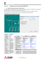
A700 VFD On SSCNet III - General Considerations
With the presence of the FR-A7NS card, the Drive will always power up in NET mode.
This will prevent typical set up access for Offline Auto Tuning, running in PU mode, or any manual control.
In order to allow the unit to go to PU mode (whether on PU itself or through FR-Configurator) do the
following:
•
•
•
•
Set pr. 499 to “9999”
Disconnect the SSCNet (Useful if the control application may have the All Servo ON command
active on power up)
Cycle Power
Switch to PU mode using the PU controls (if this will not switch make sure drive is in “Stop” mode)
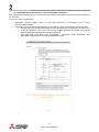
If control and parameter changes are desired to be changed/set from FR-Configurator then:
•
•
•
•
Make sure Pr 77 is set to “2” so you can write parameters in any mode
Set Pr 551 to “3” if using the USB port from FR-Configurator to manually control the drive operation
(very convenient if the motor is not visible from the drive panel or nearby the PC location)
Power Cycle the drive after changing Pr. 551
Then choose “View/Navigation/Test Operation” to get the control panel on your FR-Configurator
screen:
Once the drive is available in PU mode the normal set up and configuration of the drive can be done.
Offline Auto Tuning and any Manual tuning should be done while in this mode.
The drive can also be utilized to jog that axis and verify rotation direction, encoder setting, gear ratios and speed
settings desired.
When modifications and settings are complete return the drive to Network control:
•
•
•
•
•
•
Set Pr. 499 back to “0”
Set Pr. 77 back to default “0” if desired
Set Pr. 551 back to the Default “2” (PU is in control when in PU mode)
Reconnect SSCNet if disconnected
Power Cycle Drive
Recommend PCPY be performed at this point to save the parameters in the PU
o Set “PCPY” to “1”, will flash “PCPY” when complete
1-1
R72-125-SLSASG-001
Chapter 2
A700 Motion Control through Q170M/Q173D
2.1 A700 VFD Can be used together with Servo Axes
With the addition of the SSCNet III card, the A700 VFD can be included on the SSCNet bus and operated
through the motion controller in a way very similar to the Servos.
The Main difference is that Parameters CANNOT be written across SSCNet III by the Motion Controller.
The two types of Axes – Servo and VFD can also be operated together on the same bus:
2-1
R72-125-SLSASG-001
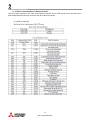
2.2 VFD Error Codes and how to reset
The A700 VFD will properly report back the error codes to the Motion Controller through SSCNet and can be
observed in MT Developer 2 using the various Monitor function displays already built in to MT Dev 2.
Those code numbers for the VFD Axes are correct, but the Descriptions provided in the software are those for
the Servo Errors only.
In order to properly annunciate the errors, the chart from:
Technical report: Specification of FR-A700 Connection with SV13SV22 for
Q172DCPU_Q173DCPU_Q170MCPU
Servo Error Detected signal M2408 + 20n (n = axis number) is ON when a Servo Error occurs.
Servo Errors can be reset by removing the cause and turning on Servo Error Reset command (M3208+20n)
then a Reboot as noted in the excerpt from the same technical report below:
2-2
R72-125-SLSASG-001
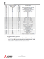
2.3 VFD Error Code Definitions in Motion Controller
The Error codes reported in this table to the Motion Controller are the VFD specific errors and will have a
different definition than those for the Servo Axis Servo Errors as follows:
2-3
R72-125-SLSASG-001
2-4
R72-125-SLSASG-001
2-5
R72-125-SLSASG-001
2.4 Trapezoidal and Advanced S-Curve functions in Motion Controller
Both Trapezoidal and Advanced S-Curve functions are available in the Motion controller and can be applied to
the VFD Axis.
There are a couple of precautions:
•
•
Trapezoidal S-Curve applies evenly at both Start and End of Acceleration, and to both
Acceleration/Deceleration
Advanced S-Curve can be applied separately at each start and finish of Acceleration and Deceleration
o Advanced S-Curve use will allow speed to continue to Increase as Acceleration moves to zero
by the ratio specified – This can result in a very prolonged, calculable, and notable rise in speed
when the Axis stop command has already been issued.
o This does NOT occur when using Trapezoidal – Acceleration stops immediately and
Deceleration begins when the Axis Stop command is issued
o
2-6
R72-125-SLSASG-001
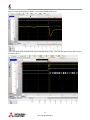
2.5 Advanced S-Curve Actual Operation
Here is a graph of an actual 20 sec Acceleration of Axis 1 interrupted by the Axis 1 Stop command
approximately 2.7 sec into a 20 sec accel. Cursor 1 is the Axis 1 Stop Command Issued, Cursor 2 where the
Deceleration begins (approximately 15.5 sec after Stop Command issued)
Note: Speed rises from 152.2 rpm to 704 rpm during this interval.
2-7
R72-125-SLSASG-001
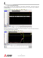
2.6 Trapezoidal S-Curve Actual Operation
Here we used the same machine and motor, with the only change being to use the Trapezoidal S-Curve with the
same 20 sec Accel, 3 sec Decel we used on the Advanced S-Curve:
Note the immediate response to the Stop Command – Acceleration is abruptly taken to zero and Deceleration
started. This is with the S-Curve set to 100%
While both are extremely useful, their application is quite different.
Be sure that the appropriate structure is used for the application at hand.
2-8
R72-125-SLSASG-001
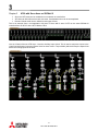
Chapter 3
•
•
•
A700 with Servo Axes on SSCNet III
Servo and VFD axes can be combined on one network as noted before
VFD Axis can follow Servo Axis and vice-versa: Coordinated motion can be accomplished
Real and Virtual mode can be utilized for both types of Axes
This is an example from a real application: 29 Axes of Servo with 2 axes of VFD on the same SSCNet III
controlled from an IQ PLC with 2 Q173 Motion CPU’s
Here is a Detail of the two VFD Axes – Note the Auxiliary Input circled. This is used to add pulse counts to the
virtual line-shaft speed command (Speed Limit for those axes in Torque Mode) which will keep the Speed limit
above the running speed of the web.
3-1
R72-125-SLSASG-001
Chapter 4
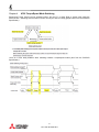
A700 Torque/Speed Mode Switching
Speed and Torque Control can be switched to/from “On the Fly” in either Real or Virtual mode using the
SV22Y03 OS – Switching to/from Position Control can only be done at a Stop (graphic taken from the SV22Y03
Specification)
There is no time delay between when switching between Torque/Speed modes (also from the SV22Y03
Specification):
4-1
R72-125-SLSASG-001
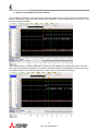
4.1 Speed to Torque Mode Low Torque settings
This is a Motion Graph taken of the motor Speed (Yellow) and Motor Current (Pink) for a drive in Speed mode at
600 rpm, switching to Torque mode with a Speed Limit of 600 rpm, Torque Command Set to 30% (cursor 1 is at
the mode change command):
There is little change in speed because there is sufficient Torque available to overcome the inertia of the motor
This is the same change from Speed to Torque Mode at 600 rpm Speed Command/Speed Limit but with Torque
Command set down to 15% (Note the slight drop of about 16 rpm in speed after the change):
4-2
R72-125-SLSASG-001
Here is a close up of that drop in speed – notice it only lasted about 65 ms:
This is the same speed command with Torque Command set to 10% - Note that the speed drop is about 33 rpm
and lasts 148 ms:
4-3
R72-125-SLSASG-001
4.2 Torque to Speed Mode Switching
Here is a graph of the same motor switching from Torque Mode to Speed Mode – Note that the speed just
increases slightly to the set point smoothly because the full value of Pr 22 (Torque Limit) is available to
accelerate the motor:
And here is Speed Mode with a load applied to the shaft, then switched to Torque mode (Torque Command =
10%, Speed Limit/Command set to 600 rpm)
4-4
R72-125-SLSASG-001
Chapter 5
A700 Torque Mode Tuning Notes
5.1 General Notes on Using Torque Mode
•
•
•
•
It is essential that Speed Limit not be reached if Torque Control is critical
o At Speed Limit, the mode of Operation changes to Speed mode but has the full amount of Pr.
22 available – which can be quite excessive relative to the Torque Setting
o An Example would be an Unwind application where the Unwind axis Speed limit is dropped
below the current Web speed. The Unwind will go to into a speed mode but the torque output
will climb as the Unwind fights the Speed controlling axis until the web is damaged
o This is different from a commanded Speed mode where a device for Torque limit can be set in
place of Pr. 22 – which is typically 150-300% to prevent Overcurrent during stopping/starting
Stopping In Torque Mode: If Web Tension cannot be lost while stopping, the Axis Stop Command must
be used (M4800 for Axis 1 for example).
If Rapid Stop Command is used, the axis will stop as fast as commanded with no torque control and
web tension control will be lost
o This may be acceptable for an Emergency Stop situation depending on the application
o Some applications with large inertial loads may allow 2 sec to bring the load to a stop which
may be attainable using the Axis Stop Command with a Deceleration of 2 seconds as an
alternative to Rapid Stop
Note that use of the Advanced S-Curve in the Motion Parameter Blocks or K-Blocks will extend time to
decelerate so Rapid Stop may be required (bypasses use of S-Curve during the stop)
5.2 Notes on Tuning A700 VFD for Torque Mode control
This may have additional reference after meetings prior to Technical Summit:
In running 3 axes of VFD in a Unwind/Rewind application (1 Axis running in Speed/Position mode, the other two
in Torque mode) we had an issue with web material “bouncing” in an excessive way causing loss of tension
control and affecting roll quality
(See video: Mark Andy VLI Bounce Issue with Inertia Comp OFF_IMG_1037.MOV)
This application had a very high reflected inertia ratio (in the video about 123:1) which makes tuning very difficult.
After exhausting all avenues noted in the manual we attempted the approach recommended by our Senior Field
operatives: Tuning in Speed mode from the PU before running Torque mode following these steps:
•
•
Obtain Large Inertial Load (preferably the maximum the system is designed for)
Calculate the Maximum Speed and the Accel time needed for Example: 40” Max Dia Roll, Max Web
Speed 950 ft/min, Accel min = 3 seconds so:
[(950 ft/min)*(12”/ft)*(Rev/40”*Pi)]*(Gear Ratio)/1750rpm*60Hz = Freq for Top Speed
{[(950*12)/(40*Pi)]*(1.53)/1750}*60 = 4.76 Hz
•
•
•
•
•
•
•
•
•
Set A700 into PU mode, set Pr 20 = 4.76Hz (Frequency to attain top Web Speed)
Set A700 Pr 7/8 (Accel/Decel) to 3 sec (min Accel/Decel time)
Enable EZ Gain Tuning (Pr. 819 to “1” to enable EZ Gain tuning)
Set Pr 818 to a high value to begin (15 for our test)
Graph Motor Speed and Motor Torque on FR-Config Oscilloscope utility
Start and let roll reach full web surface speed, Stop and Start a few times
Continue to Stop and Start, Adjusting Pr 818 down until the Speed Curve approaches a smooth ramp
up with little or no overshoot and settles quickly
Turn Off EZ Gain when results are not improved by lowering pr 818
Read all parameters and make note of new Pr. 880 setting, Pr.820, & Pr 821 settings
5-1
R72-125-SLSASG-001
•
•
•
•
•
•
If further adjustment is needed manually, start with Pr 820 Speed P Gain until overshoot minimized
Then adjust Pr 821 (Speed Integral Gain) until the speed graph settles quickly and with a minimal
bounce
When satisfied, reset Pr 20 to 60 hz, and rest pr. 499 to get unit back in Net Mode, cycle power and run
machine to test Torque Mode operation
Set Pr. 7 and Pr. 8 to 0.1 sec after tuning is complete before going back to torque control
If needed Torque Mode Gains (Pr. 824 – P Gain, and Pr. 825 I Gain, can be adjusted to refine the
torque control.
Show video of Same Web Material at the same 950 fpm web speed, 3 sec accel, with NO torque
parameters tuned off of defaults:
Mark Andy VLI Post Tuning - LabelStock 3s Accel to 950 fpm_Bad Unwind Roll Quality_IMG_1048.MOV
5-2
R72-125-SLSASG-001
Chapter 6
A700 Parameter/Function Restrictions on SSCNet III
6-1
R72-125-SLSASG-001
6-2
R72-125-SLSASG-001
6-3
R72-125-SLSASG-001
6-4
R72-125-SLSASG-001
6-5
R72-125-SLSASG-001
6.1 A700 Inverter I/O Terminal Function List
6-6
R72-125-SLSASG-001
6-7
R72-125-SLSASG-001
6-8
R72-125-SLSASG-001
Chapter 7
Terminology
7-1
R72-125-SLSASG-001
Revisions
Original release
5/3/2012
Rev-1
R72-125-SLSASG-001