1
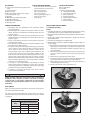
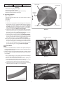
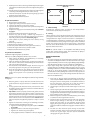
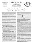
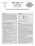
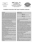
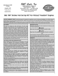
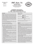
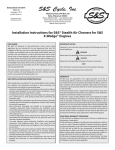
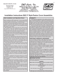
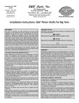
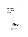
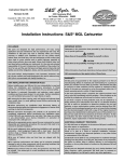
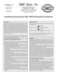
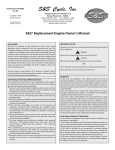
S&S Cycle, Inc
®
Instruction 106-5986
02-22-13
.
Copyright © 2010, 2013
by S&S Cycle, Inc.
14025 Cty Hwy G PO Box 215
Viola, Wisconsin 54664
Phone: 608-627-1497 • Fax: 608-627-1488
All rights reserved.
Printed in the U.S.A.
Technical Service Phone: 608-627-TECH (8324)
Technical Service Email: [email protected]
Website: www.sscycle.com
Installation Instructions: S&S 97" & 106" Big Bore Kits
for 1999–’06 & 2007–Up Big Twins
DISCLAIMER:
IMPORTANT NOTICE:
S&S parts are designed for high performance, closed course, racing
applications and are intended for the very experienced rider only. The
installation of S&S parts may void or adversely affect your factory warranty.
In addition such installation and use may violate certain federal, state, and
local laws, rules and ordinances as well as other laws when used on motor
vehicles used on public highways, especially in states where pollution laws
may apply. Always check federal, state, and local laws before modifying
your motorcycle. It is the sole and exclusive responsibility of the user to
determine the suitability of the product for his or her use, and the user shall
assume all legal, personal injury risk and liability and all other obligations,
duties, and risks associated therewith.
Statements in this instruction sheet preceded by the following words are of
special significance.
WARNING
Means there is the possibility of injury to yourself or others.
CAUTION
Means there is the possibility of damage to the part or motorcycle.
NOTE
Other information of particular importance has been placed in italic type.
S&S recommends you take special notice of these items.
The words Harley®, Harley-Davidson®, H-D®, Sportster®, Evolution®, and all
H-D part numbers and model designations are used in reference only. S&S
Cycle is not associated with Harley-Davidson, Inc.
WARRANTY:
All S&S parts are guaranteed to the original purchaser to be free of
manufacturing defects in materials and workmanship for a period of twelve
(12) months from the date of purchase. Merchandise that fails to conform to
these conditions will be repaired or replaced at S&S’s option if the parts are
returned to us by the purchaser within the 12 month warranty period or within
10 days thereafter.
SAFE INSTALLATION AND OPERATION RULES:
Before installing your new S&S part it is your responsibility to read and follow
the installation and maintenance procedures in these instructions and
follow the basic rules below for your personal safety.
Gasoline is extremely flammable and explosive under certain conditions
and toxic when breathed. Do not smoke. Perform installation in a well
ventilated area away from open flames or sparks.
If motorcycle has been running, wait until engine and exhaust pipes
have cooled down to avoid getting burned before performing any
installation steps.
Before performing any installation steps disconnect battery to eliminate
potential sparks and inadvertent engagement of starter while working
on electrical components.
Read instructions thoroughly and carefully so all procedures are
completely understood before performing any installation steps.
Contact S&S with any questions you may have if any steps are unclear or
any abnormalities occur during installation or operation of motorcycle
with a S&S part on it.
Consult an appropriate service manual for your motorcycle for correct
disassembly and reassembly procedures for any parts that need to be
removed to facilitate installation.
Use good judgment when performing installation and operating
motorcycle. Good judgment begins with a clear head. Don’t let
alcohol, drugs or fatigue impair your judgment. Start installation when
you are fresh.
Be sure all federal, state and local laws are obeyed with the installation.
For optimum performance and safety and to minimize potential
damage to carb or other components, use all mounting hardware that is
provided and follow all installation instructions.
Motorcycle exhaust fumes are toxic and poisonous and must not be
breathed. Run motorcycle in a well ventilated area where fumes can
dissipate.
••
In the event warranty service is required, the original purchaser must call or
write S&S immediately with the problem. Some problems can be rectified by a
telephone call and need no further course of action.
••
A part that is suspect of being defective must not be replaced by a Dealer
without prior authorization from S&S. If it is deemed necessary for S&S to
make an evaluation to determine whether the part was defective, a return
authorization number must be obtained from S&S. The parts must be packaged
properly so as to not cause further damage and be returned prepaid to S&S
with a copy of the original invoice of purchase and a detailed letter outlining
the nature of the problem, how the part was used and the circumstances at
the time of failure. If after an evaluation has been made by S&S and the part
was found to be defective, repair, replacement or refund will be granted.
••
••
••
ADDITIONAL WARRANTY PROVISIONS:
(1) S&S shall have no obligation in the event an S&S part is modified by any
other person or organization.
(2) S&S shall have no obligation if an S&S part becomes defective in whole or
in part as a result of improper installation, improper maintenance, improper
use, abnormal operation, or any other misuse or mistreatment of the S&S part.
(3) S&S shall not be liable for any consequential or incidental damages
resulting from the failure of an S&S part, the breach of any warranties, the
failure to deliver, delay in delivery, delivery in non-conforming condition, or
for any other breach of contract or duty between S&S and a customer.
(4) S&S parts are designed exclusively for use in Harley-Davidson® and other
American v-twin motorcycles. S&S shall have no warranty or liability obligation
if an S&S part is used in any other application.
••
••
••
••
1
KIT CONTENTS
(2) 3.927" pistons (front and rear pistons are the
same)
(2) 0.927" piston pins
(4) Piston pin clips
(2) Ring packs which include the top, second,
oil rail, and expander rings
(2) Cylinders
(2) MLS (Multi Layer Steel) head gaskets
(2) Cylinder base O-rings
(2) Cylinder base dowel O-rings
(2) Exhaust gaskets
SPECIAL TOOL REQUIREMENTS
• Harley-Davidson® service manual for the
specific model you are working on
• Piston C-clip installer
• Piston ring compressor
• Piston ring expander
• Piston ring end gap filing tool
• Digital or dial calipers
• Feeler gauge
GENERAL INFORMATION
Thoroughly read and understand all the instructions before
starting installation.
S&S 106" big bore kits contain 3.927" bore pistons with 1.090" deck
height. These kits are intended for stock stroke (4.375") 2007–up
big twin engines.
S&S 97" big bore kits contain 3.927" bore pistons with 1.270" deck
height. These kits are intended for stock stroke (4.000") 1999–’06
big twin engines.
Pistons are the same for the front and rear cylinders and can be
used with either cylinder.
The 3.927" piston is marked with an arrow that should point to the
front of the engine when installed.
The pistons are machined during manufacturing, to provide the
correct running clearance when cylinders are bored to nominal
size of 3.927". In other words the clearance it built into the
piston diameter. If you wish to confirm piston diameter be sure
to measure the piston only at the micrometer windows on the
front and rear skirts of the piston. Measuring the piston in areas
with non-stick coating applied will result in incorrect readings.
Cylinder measurements must be taken with the cylinder in torque
plates with bolts tightened at correct torque value to simulate
conditions in an assembled engine.
In all cases it is the engine builder’s responsibility to confirm
proper clearances when assembling an engine. This is especially
critical with performance components such as larger valve, high
performance heads and high lift camshafts.
In addition to clearances mentioned, 0.060" valve to piston
clearance must be confirmed.
INSTRUCTION CONTENTS
General Information
Disassembly
Installation and Reassembly
A- Setting Ring End-Gap
B- Piston Ring Installation
C- Piston Installation
D- Cylinder Installation
E- Cylinder Head Installation
F- Final Assembly
E- Break-in Procedure
INSTALLATION AND REASSEMBLY
A- Setting Ring End Gaps
NOTES
Important! The gap of the second ring should be larger than the top ring;
this will help keep the top ring seated for improved performance.
Each ring should be fitted to the particular cylinder in which they will be
installed.
Oil rails can be installed without adjusting the end gap. The minimum
gap should be 0.010"
Never alter the end gap of the oil expander ring.
Always install the ends of the expander facing up as shown in Picture 3,
top of next page.
1- Thoroughly wash cylinders with hot soapy water, then wash with
brake cleaner and wipe with a clean white towel. Repeat until
towel does not show evidence of debris and apply a light coat
of oil immediately.
2- Check the ring end gap by placing the ring into the cylinder. Use
a piston or caliper to ensure that the ring is placed squarely in
the bore.
3- Measure the ring end gap with a feeler gauge.
4- See table for proper end gap measurement. If adjustment to the
gap must be made, use a proper ring end gap filing tool.
5- Always file from the ring face towards the inside diameter to
avoid damaging the face coating.
6- Remove material from only one end of the ring.
••
••
••
••
••
••
••
••
••
••
••
••
••
CAUTION
Failure to follow instructions and perform required clearancing,
installation and/or break-in procedures may result in damage
to pistons and or other engine components not covered under
warranty. The proper break-in procedure is in Section 4 of these
instructions.
DISASSEMBLY
Refer to the Harley-Davidson® manual for your specific motorcycle for
the correct disassembly procedure.
Picture 1
The engine should be disassembled to the short block i.e. induction
system, exhaust system, cylinder heads, cylinders, and pistons should
be removed.
Suggested ring end gaps
Ring
Ring Gap Tolerance (inches)
Min
Max
Top
0.016
0.022
2nd
0.016
0.026
Oil ring rails
0.010
0.050
Picture 2
2
Incorrect overlap
Incorrect orientation
Top Ring Gap
Correctly butted tips facing up
Top Oil Rail Gap
Picture 3
7- Ensure that ring end gaps are square.
8- Remove sharp edges and burrs.
9- Recheck gap measurement and adjust as necessary.
10-Repeat procedure with the other rings.
CAM SIDE
B- Piston Ring Installation
Order of installation
1- Oil ring expander (ends must face up as shown in Picture 3, above)
2- Oil ring rails
3- 2nd ring
4- Top ring
DRIVE SIDE
Expander
Ring Gap
1- Install the oil ring expander to the bottom groove of the piston.
The expander ring has a gold finish. Make sure the end of the
expander ring is butted together and not overlapping (Picture
3, above). If the tips are overlapped, excessive oil consumption
will occur. Orient the expander gap such that it can be viewed as
it enters the cylinder. See Picture 5c, bottom right.
2- Install oil rails. The oil rails are the thinnest of all the rings. Either
side can be placed up. Use a ring expander to install the rails into
the groove. Install one rail above the expander, and one below.
Orient the gaps according to Picture 5a, top right.
3- Install the 2nd ring with the dot facing up (see Picture 4, below).
The 2nd ring has a dull black finish and is the thickest of all the
rings. Use an expander to install the ring to the 2nd groove in the
piston. Orient the gap according to Picture 5a, top right.
4- The top ring must be installed with the dot or letter facing up.
If there is no marking, the top ring can be installed with either
face up. The top ring has a chrome edge and is thicker than the
oil rails. Use a ring expander tool to install the ring to the top
groove. Orient the gap according to Picture 5a, top right.
Second Ring Gap
Bottom Oil Rail Gap
Picture 5a
Expander ring gap
C- Piston Installation
NOTES
Pistons are identical and can be installed in either cylinder. Each piston
is stamped “FWD" or has an arrow which must point toward the front of
the engine when assembled.
Check piston pin to connecting rod bushing clearance. Clearance should
be between 0.0007" and 0.0012". Bushing should be replaced if clearance
exceeds 0.002".
••
••
1- Place rubber tubing over the cylinder studs to prevent damage
to the pistons and rings during assembly.
2- Place a clean sheet of plastic over the crankcase openings to
prevent anything from dropping into the crankcase.
3- Install one of the piston pin clips into each of the pistons. Make
sure the piston pin clip opening is facing up when installed.
4- Lightly oil the piston pin, piston pin bore and upper connecting
rod bushing with clean 20W-50 oil or assembly lube.
Picture 5b
Picture 5c
Picture 4
3
Head Bolt Tightening Sequence
Cam Side
5- Hold the piston over the connecting rod with the piston facing the
correct direction and the piston pin bore and upper bushing bores
lined up.
6- Install the piston pin through the piston pin bore and through the
connecting rod bushing until the pin contacts the clip.
7- Install the other piston clip with the opening facing up. Ensure
that both clips are fully seated.
8- Repeat procedure for the rear piston.
4
3
FRONT CYLINDER
D- Cylinder Installation
2- Bring the front cylinder to TDC.
3- Apply a light coating of oil to the piston and rings.
4- Install the cylinder base o-ring on the cylinder.
5- Lightly oil the new o-rings for the lower cylinder deck alignment
dowels and install.
6- Verify that the ring gaps are orientated correctly, refer to Picture
5a, page 3.
7- Remove the rubber tubing from the cylinder studs.
8- Compress ring pack by using a suitable ring compressor. If
possible, position the ring compressor so that you can see the oil
expander gap during installation. Picture 5b, page 3.
9- Install cylinder on piston, making sure not to overlap oil ring
expander.
10-Remove ring compressor.
11-Remove plastic sheeting covering crankcase.
12-Slide the cylinder down until it seats against the crankcase.
13-Rotate the engine until the rear cylinder is at TDC.
14-Repeat procedure for the rear cylinder.
1
3
4
REAR CYLINDER
2
2
1
Drive Side
Picture 6
F- Final Assembly
Assemble the remaining items according to the Harley-Davidson
service manual specific for your motorcycle.
G-Tuning
S&S big bore kits increase the displacement and compression ratio of
your engine. The fuel and ignition systems must be calibrated for these
changes before the engine is driven and break-in is attempted. It is
recommended that a performance carburetor such as the S&S Super E
or G be used with the correct jetting for the engine size for carbureted
models. Fuel injected engines must be tuned using a replacement
ECU such as the S&S VFI module, or an aftermarket tuner such as the
DynoJet® Power Vision® tuner.
NOTE: The S&S VFI module is not compatible with 2008–up Touring
models with electronic throttle control. S&S recommends the Dynojet®
Power Vision® tuner for these applications.
E- Cylinder Head Installation
Head Gasket Tightening Torque Specifications
Multi layer steel (MLS) head gasket, PN 106-3714, 3.927" bore.
1- Check surfaces for flatness and imperfections, an excessively
rough finish may cause gasket failure.
2- Check all hardware for defects. Clean all threads and lubricate
with clean oil. Lubricate the underside flange of the head bolts
with clean oil (wipe away excess).
3- The head bolts are two different lengths. The short ones go on
the spark plug side; the long ones go on the pushrod side.
4- Place the head gasket on the cylinder and locate the gasket
using the cylinder head alignment dowels. Either face of the
gasket can be up, there is not a specific top or bottom to the
gasket.
BREAK-IN PROCEDURE
NOTES:
S&S engines and parts are designed for high performance and are not
as tolerant of inadequate break-in. Correct break-in will assure longer
engine life and will prevent unnecessary engine damage. Engine damage
caused by improper break-in is not covered under the S&S Warranty.
Proper engine tuning will be required in order for your engine to run
correctly and to prevent damage. Carbureted engines must be rejetted,
and a larger carburetor is recommended. EFI calibration can be changed
with the use of an S&S VFI module or other aftermarket tuner. It is
recommended to start by adding 10% fuel across the map if you do not
have a tune file for the set-up you are running. Check the S&S website for
Power Vision calibration files.
••
••
NOTE: Do not use the cylinder head alignment dowel O-rings with MLS
head gasket.
1- Initial start up. Run the engine approximately one minute at
1250-1750rpm. DO NOT crack the throttle or subject to any loads
during this period as head gaskets are susceptible to failure at
this time. During this time, check to see that oil pressure is
normal, oil is returning to the oil tank and no leaks exist.
2- Shut off engine and inspect for leaks. Allow engine to cool to the
touch.
3- Start up engine again and allow the engine to warm up for 3 to 4
minutes. Again, do not crack the throttle or subject the engine to
any type of load. Shut down the engine and allow to cool. Repeat
this procedure at least 3 more times.
4- After the engine has cooled to room temperature, you are ready
to start the 500 mile engine break-in process.
5- The first 50 miles are the most critical for new rings and piston
break-in. Engine damage is most likely to occur during this
period. Keep heat down by not exceeding 2500rpm. Avoid
lugging the engine, riding in hot weather or in traffic. Vary the
engine speed. We recommend changing the oil after the first 50
miles.
6- The next 500 miles should be spent running no faster than
3500rpm or 60mph. Avoid running continuous steady speeds,
and do not lug the engine, Vary the rpm. We recommend
changing the oil again at 500 miles.
5- Once the gasket is in place, make sure that it fits the bore. The
gasket should not hang into the bore or combustion chamber
area.
6- If using cylinder heads other than stock, check the brass rivets
of the MLS gaskets to ensure the rivets do not interfere with the
sealing surface in any way.
7- Important! In order to properly seal the head gasket, the head
bolts must be torqued in the sequence shown in the next step,
fully loosened, then torqued again a 2nd time. Follow the head
tightening sequence in the next step then fully loosing the head
bolts ¼ turn at a time in the sequence shown in Picture 6 until
fully loose. Repeat the tightening sequence in step 8 a second
time.
8- Tighten the head bolts according to the following procedure,
start with the front head then the rear head.
a- Tighten each bolt finger tight using the sequence in Picture
6, top right.
b- Tighten each bolt to 10-12 ft-lbs using the sequence.
c- Tighten to 15-17 ft-lbs using the sequence.
d- Finally, tighten the bolts an additional ¼ turn (90 degrees).
4
7- For the balance of the first 1000 miles the engine can be run in
a normal but conservative manner. You can be more liberal with
the rpm range and the motorcycle can be operated at normal
highway speeds. Avoid overheating or putting any hard strain
on the engine; no drag racing, dyno runs, excessive speed, trailer
towing or side car operation.
8- After 1000 miles, change the engine oil. Now the motorcycle can
be operated normally.
OIL RECOMMENDATIONS
S&S® Cycle recommends the use of S&S 20W-50 synthetic or petroleum
based V-Twin Motor Oil.
Break-in can be performed with either synthetic or petroleum based oil.
Regardless of what type of oil you select, be sure to only use oil specifically
designated for use in an air cooled motorcycle engine. If you prefer
not to use a multi-viscosity oil, utilize the viscosity suggested for the
temperature you will be operating your motorcycle in.
Viscosity
Ambient Temperature (°F)
SAE 20W50
Normal Operating Conditions
30°–100°
SAE 10W40
Consistantly Below 40°
SAE 60
Consistently Above 80°
5