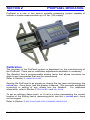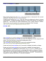
1
ProPanel™
User Manual for:
ProPanel-HD & -HDE
Readout Serial # ______ Linear Multiplier ______
WARRANTY
Accurate Technology, Inc., warrants the ProPanel Digital Measuring System
against defective parts and workmanship for 1 year commencing from the
date of original purchase. Upon notification of a defect, Accurate Technology,
Inc., shall have the option to repair or replace any defective part. Such
services shall be the customer's sole and exclusive remedy. Expenses
incidental to repair, maintenance, or replacement under warranty, including
those for labor and material, shall be borne by Accurate Technology, Inc.
(Including freight or transportation charges during the first 30 days).
Except as expressly provided in this warranty, Accurate Technology, Inc.,
does not make any warranties with respect to the product, either expressed or
implied, including implied warranties of merchantability or fitness for a
particular purpose, except as expressly provided in this agreement.
Accurate Technology, Inc., shall not be liable for any special, incidental, or
consequential damages or for loss, damage or expense directly or indirectly
arising from the customer's use of or inability to use the equipment either
separately or in combination with other equipment, or for personal injury or
loss or destruction of other property, or from any other cause.
To request repair work (either warranty qualified parts or not), contact
Accurate Technology, Inc. directly by phone, fax, or e-mail. A Returned
Merchandise Authorization (RMA) number is required before returning a
product for repair.
Accurate Technology, Inc.
+1 828.654.7920
800.233.0580
828.654.8824 (F)
www.proscale.com
[email protected]
SAFETY WARNING
Before using this product on or around any
machinery disconnect all machinery power.
Manual # 800-1090-105 Rev A
Copyright © 2010, Accurate Technology, Inc. All rights reserved.
ProPanel-HD
Page 2 of 40
Table of Contents
SECTION 1
GENERAL INFORMATION................................................ 5
INTRODUCTION............................................................................................ 5
PROPANEL SPECIFICATIONS ........................................................................ 5
SECTION 2
PROPANEL OPERATION ................................................. 6
CALIBRATION ............................................................................................. 6
OUTSIDE MEASURING:................................................................................. 7
INSIDE MEASURING ..................................................................................... 7
MAINTENANCE ............................................................................................ 7
SECTION 3
READOUT OPERATION ..................................................... 8
FUNDAMENTAL OPERATION.......................................................................... 8
KEY TIMING .......................................................................................... 8
KEY FUNCTIONS FOR STANDARD OPERATION ................................................. 9
ON/OFF KEY ......................................................................................... 9
UNITS KEY ........................................................................................... 9
PLUS (+) & MINUS (–) KEYS ..................................................................10
DATUM KEY ........................................................................................10
BASIC FUNCTIONS......................................................................................11
KEY LOCK ...........................................................................................11
DISPLAY RESOLUTION ..........................................................................11
DISPLAYED MEASUREMENT UNITS..........................................................11
AUTO ON/OFF ......................................................................................12
LINEAR SCALING ..................................................................................12
UPPER/LOWER LIMITS ..........................................................................12
ADVANCED F UNCTIONS ..............................................................................13
ABSOLUTE VS INCREMENTAL MEASUREMENTS. .......................................13
ABS ...................................................................................................13
INC ....................................................................................................13
SEND .................................................................................................14
OFFSET ADDITION ................................................................................14
PROGRAMMABLE OUTPUT OPERATION ...................................................15
PROGRAMMABLE OUTPUT POLARITY ......................................................15
EXTERNAL KEYPAD INPUT .....................................................................16
SPECIAL FUNCTIONS ................................................................................16
SPECIAL FUNCTIONS ................................................................................17
SPECIAL FUNCTION 1: MONITOR, HOLD, DELETE ......................................17
SPECIAL FUNCTION 2: GO/NOGO ...........................................................19
SPECIAL FUNCTION 3: ACCUMULATOR ...................................................20
SPECIAL FUNCTION 4: STATISTICS ........................................................22
COMPENSATION F UNCTIONS .......................................................................24
TEMPERATURE COMPENSATION.............................................................24
NON-LINEAR COMPENSATION ................................................................25
ProPanel-HD
Page 3 of 40
CHANGING THE BATTERY ............................................................................28
CIRCUIT BOARD JUMPERS ..........................................................................28
SECTION 4
PROGRAMMING ................................................................30
Pr 1 – Datum Key.............................................................................31
Pr 2 – Direction................................................................................31
Pr 3 – Key Lockout..........................................................................31
Pr 4 – Display Resolution ...............................................................31
Pr 11 – Displayed Measurement Units ...........................................32
Pr 12 – Auto-Off Time......................................................................32
Pr 13 – Linear Compensation .........................................................32
Pr 14 – ProScale Compatibility.......................................................32
Pr 21 – Backlight Control................................................................33
Pr 22 – ABS/INC Key Operation......................................................33
Pr 23 – Auxiliary Keypad Enable ....................................................33
Pr 24 – Special Functions. ..............................................................33
Pr 25 – Special Functions Option. ..................................................33
Pr 26 – Monitor Drift Tolerance.......................................................33
Pr 27 – Use Soft Limits....................................................................34
Pr 28 – Lower Soft Limit Position. ..................................................34
Pr 29 – Upper Soft Limit Position. ..................................................34
Pr 30 – Offset Addition Enable. ......................................................34
Pr 31 – Offset Addition Preset 1. ....................................................34
Pr 32 – Offset Addition Preset 2. ....................................................34
Pr 33 – Offset Addition Preset 3 .....................................................35
Pr 34 – Offset Addition Preset 4 .....................................................35
Pr 35 – External Keypad Input 1. ....................................................35
Pr 36 – External Keypad Input 2. ....................................................35
Pr 37 – Programmable Output Polarity ..........................................36
Pr 38 – Programmable Output Operation.......................................36
Pr 39 – Non-Linear Compensation Enable. ....................................37
Pr 40 – Non-Linear Compensation Interval. ...................................37
Pr 41 – Temperature Compensation Enable. .................................37
Pr 42 – Temp. Comp. Low Position. ...............................................37
Pr 43 – Temp. Comp. High Position. ..............................................37
Pr 44 – Temperature Compensation Coefficient............................37
SECTION 5
MISCELLANEOUS .............................................................38
FREQUENTLY ASKED Q UESTIONS ................................................................38
DATA T RANSMISSION .................................................................................39
ACCESSORIES ...........................................................................................39
ProRF SPC ..........................................................................................39
SPC Converter ....................................................................................39
ProPanel-HD
Page 4 of 40
SECTION 1
GENERAL INFORMATION
Introduction
ProPanel™ is a general-purpose portable measuring tool. It is ideal for
making edge to edge measurements up to 100 inches (2.5m). It has been
designed using high quality extruded and machined parts to provide the best
accuracy and repeatability.
The measurement technology used in this model ProPanel is a ProScale®
Model 580 Digital Measuring System.
ProScale digital measuring systems are affordable precision electronic
devices for making linear measurements with speed and accuracy. ProScale
consists of a SCALE, an ENCODER (also called READHEAD) and a DIGITAL
READOUT (DRO). ProPanel uses Inductive Incremental measuring technology.
ProPanel Specifications
Measuring Range:
Up to 60 Inches (1.5m), or
Up to 100 Inches (2.5m)
Accuracy:
Accuracy:
± .015in (±.4mm) uncompensated mode
± .005in (±.13mm) compensated mode (HDE model)
Resolution:
.1inch
.01inch
.001inch
.0005inch
1/16inch
Repeatability:
.001in or .01mm or .001cm
Display Range:
± 999.999 in; ± 399 63/64 in
± 9999.99 mm; ± 999.999 cm
Operating Temp:
32 to 120°F
Temp Coefficient:
13ppm/ °F
Max. Slew Rate:
60 inches/sec. (1500mm/sec)
Power:
Two AA Alkaline Batteries
Output Format:
Mitutoyo Digimatic® SPC
ProPanel-HD
.1mm
.01mm
.01mm
.01mm
1/32inch
.1cm
.01cm
.001cm
.001cm
1/64 inch
or
or
or
or
0 to 51°C
25ppm/°C
Page 5 of 40
SECTION 2
PROPANEL OPERATION
ProPanel is a one or two person portable measuring system capable of
outside or inside measurements up to 2.5m (100 inches).
Calibration
The accuracy of the ProPanel system is dependent on the manufacturing of
the ProScale. There are no calibration adjustments available or necessary.
The Readout has a programmable scaling factor that allows correction for
slight linear inaccuracies that may be encountered.
Refer to Section 3: LINEAR SCALING
Zeroing the ProPanel is as simple as closing the two jaws and pressing the
key. Once done, lock the display if desired. This prevents accidental
re-zeroing or setting of any offsets into the Readout. For additional
information, refer to Section 3: DATUM KEY and KEY LOCK
DATUM
To set an arbitrary datum point, or to set in a value representing the current
location of the Sliding Jaw or measuring point, use the +, DATUM and – keys
on the keypad.
Refer to Section 3: KEY FUNCTIONS FOR STANDARD OPERATION
ProPanel-HD
Page 6 of 40
Outside Measuring:
Use ProPanel like a T-square. Close the jaws against the edge(s) of the
article being measured, and read the result on the LCD.
Note: Whenever possible, use the full width of the jaw for measurements.
This ensures the most consistent and accurate measurements.
Inside Measuring
Push the F1 key until the LCD shows a “1”. This indicates the value
programmed for offset addition 1 (Programming Parameter Pr31), will be
automatically applied to any measurement.
Using the upper or lower tips of the ProPanel jaws, measure the inside
dimension of interest and read the result on the LCD.
NOTE: Programming Parameter Pr30 – Offset Addition Enable, and Programming
Parameter Pr31 – Offset Addition 1, have been preprogrammed for your
convienence.
Programming Parameter Pr30 has been programmed to 1
Programming Parameter Pr31 has been programmed to 24.00mm
Maintenance
ProPanel will operate in a dry environment with non-conductive debris such
as sawdust, plastic, dust, and small amounts of water splash with no adverse
effects. The system should be cleaned of excess debris when necessary to
prevent premature damage to the Scale or Encoder.
The Digital Readout should be cleaned periodically with compressed air to
remove any dust on the lens and keys.
All mounting fasteners should be checked occasionally for tightness.
Occasionally check parallelism of the jaws by measuring a piece of paper
between the upper tips of the jaws, then between the lower tips of the jaws. A
variation of 0.05mm (0.002 inches) is within specifications.
If the jaw becomes difficult to move, and the lock/thumbscrew is not tightened,
verify the scale is clean. Find and remove any burrs which may have
developed on the aluminum scale.
Do not use any liquid lubricants on the ProPanel.
ProPanel-HD
Page 7 of 40
SECTION 3
READOUT OPERATION
Fundamental Operation
All functions of the General Purpose Digital Readout are included in this
section. The operations & functions that DO NOT apply to standard ProPanel
products are shown Grayed Out.
KEY TIMING
The keys pictured below have multiple functions. Timing (how long a key is
depressed) is important. This manual uses the term “momentarily” to
describe a key press and release in less than 0.8 seconds. Whereas “press
and hold” is used to describe a key press and release taking 1 second or
longer.
See Table Below:
Momentarily
Press & Hold
How long is the key pressed?
Less than .8 seconds
More than 1 second
When is key function executed?
On key release
While holding
A function is executed upon a key release for momentary key presses.
A function is executed after the allotted time has elapsed for “press & hold”
operations. See Table Below:
Momentarily Press
Cycles measurement units:
inches, fractions, mm
Press & Hold
(in programming mode)
Increments program parameter list
Displays Pr #
Plus (+)
(in programming mode)
increments displayed value
increments parameter value
increments faster
increments faster
forces reading to programmed
datum value
forces parameter to readout’s
default
6 seconds: Shows battery voltage
9 seconds: Shows temperature
decrements displayed value
decrements parameter value
decrements faster
decrements faster
UNITS
Datum
(in programming mode)
Minus (-)
(in programming mode)
ProPanel-HD
No effect
no effect
Page 8 of 40
Key Functions for standard operation
ON/OFF KEY
Momentarily press
Momentarily press the ON/ OFF key to turn the DRO off. Momentarily press it
again to turn it back on. The Firmware version is displayed for two seconds
after power-up.
UNITS KEY
Momentarily press
Momentarily depressing the UNITS key will cycle the units that are displayed.
With each key press, the DRO will cycle through decimal inches, fractions
(16ths, 32nds, 64ths) and metric. To limit the units modes that are displayed
see Programming Parameter (Pr11).
When the DRO is in 1/16 or 1/32 inch fraction mode, a series of “bars” in the
upper right corner of the LCD, each representing 1/64th of an inch, may
appear. (ie. When in 1/16 inch mode and three bars are showing, the
measurement displayed is rounded down to the closest 1/16 inch and each
bar indicates an additional 1/64 of an inch.) For better resolution, switch to
1/32 or 1/64 mode. For the best resolution, switch to a decimal mode.
When the measurement is greater than 99 63/64 inches, a +100 and/or +200
will illuminate in the upper right portion of the display to indicate this amount
must be added to the displayed reading. ie: If the measurement is 154 5/8
inches, 54 5/8 and +100 will be illuminated on the display.
ProPanel-HD
Page 9 of 40
PLUS
(+) & MINUS (–) KEYS
Momentarily or Press & Hold
Momentarily depressing the + or – key increments or decrements the current
displayed value by one unit of measurement.
Pressing and holding the + or – key will cause the displayed value to change
continuously. Continue pressing the key to cause the amount of change to
speed up. This allows for quick adjustments over a large range of values.
These keys may be locked out to prevent accidental offset changes.
See LOCK FUNCTION and Programming Parameter (Pr3).
DATUM KEY
Momentarily press
Press & Hold
The DATUM key is used to change the currently displayed value.
Momentarily pressing the DATUM key forces the display to a user programmed
value. This can be zero or any other displayable value.
See Programming Parameter (Pr1).
The DATUM key can be locked out to prevent accidental entries.
See LOCK FUNCTION and Programming Parameter (Pr3).
Press and hold the DATUM key for 6 seconds to display the battery voltage.
Press and hold the DATUM key for 9 seconds to display the temperature.
The temperature is displayed in the format “xx.x F” or “xx.x C” where xx.x is
the temperature and the units are in degrees Fahrenheit or degrees Celsius
based on the current units setting (Inch or Metric). The temperature readout
will continue to be displayed until the datum key is released. Temperature is
sampled on startup and every 10 minutes thereafter.
ProPanel-HD
Page 10 of 40
Basic Functions
KEY LOCK
The Digital Readout provides a function that can be used to “lock-out” the
position offset adjustment keys (+, DATUM , and –) to prevent accidental
changes of the current displayed value. To activate the Lock function, press
and hold the ON/ OFF key and then momentarily press the UNITS key. The word
LOCK will be displayed in the upper left corner of the
LCD. When the LOCK symbol is displayed, the +,
DATUM and – keys become inactive.
To de-activate the Lock function, press and hold the
ON/OFF key and then momentarily press the UNITS key.
The Lock function can also be enabled through programming, allowing a more
permanent Lock function. See Programming Parameter (Pr3)
DISPLAY RESOLUTION
Four display resolutions are available:
.1in
.1mm .1cm
or
.01in .01mm .01cm
or
.001in .01mm .001cm
or
.0005in .01mm .001cm
To change the display resolution See Programming Parameter (Pr4)
Inch Resolution
4 decimal places
3 decimal places
2 decimal places
Maximum Value (Inches)
Millimeter Resolution
2 decimal places
1 decimal place
Maximum Value (mm)
99.9999
999.999
9999.99
9999.99
99999.9
DISPLAYED MEASUREMENT UNITS
The measurement units displayed on the Readout when the UNITS key is
depressed is user configurable. The table below provides a matrix for
selecting which units will be displayed.
See Programming Parameter (Pr11).
Programming Parameter Pr 11 Value
0
1
2
3
4
5
6
ProPanel-HD
Measurement Units Displayed
All inch units, metric in millimeters
Millimeters only
Decimal inches and millimeters
Decimal inches and centimeters
All inch units, metric in centimeters
Centimeters only
Decimal inches only
Page 11 of 40
AUTO ON/OFF
In order to prolong battery life, the Digital Readout has a built-in timer that will
turn off the LCD after a period of no encoder movement or key activity. This
function does NOT turn off power to the encoder; the system will not lose its
position. Auto shutoff is programmable from 0 (always on), to 240 minutes.
Press the ON/ OFF key or move the scale to wake up the DRO. Any key press
or encoder motion while the DRO is not in sleep mode will restart the auto
shutoff timer.
The default time period before the LCD turns off is 15 minutes. This time
period may be changed, or completely disabled through programming.
See Programming Parameter (Pr12).
LINEAR SCALING
All LCD Digital Readouts have the ability to “scale” the actual measurement.
This function is useful when the actual measurement must be multiplied or
divided before being displayed. Care should be taken when using this function
since invoking it will cause the unit to display a reading different than the
actual measured value.
This function has a range of: 0.00001 to 9.99999 allowing the actual
measured value to be multiplied or divided in very small or very large
increments.
See Programming Parameter (Pr13).
UPPER/LOWER LIMITS
The Digital Readout can display either LL for Lower Limit or UL for Upper
Limit if a pre-programmed upper or lower reading is exceeded. Upper and
Lower Limits are set with Programming Parameters Pr28 and Pr29 but are only
active if Pr27 is set to 1. The display toggles for 2 seconds between current
position and LL if the Lower Limit is exceeded, or UL if the Upper Limit is
exceeded. This continues as long as either limit is exceeded.
See Programming Parameters (Pr27, 28, 29).
In addition, the programmable output can be configured to activate when
either the Upper or Lower limit is exceeded.
See PROGRAMMABLE OUTPUT OPERATION.
ProPanel-HD
Page 12 of 40
Advanced Functions
The following additional functions & operations are
available on standard ProPanel products.
See PROGRAMMING PARAMETER (Pr23).
ABSOLUTE VS INCREMENTAL MEASUREMENTS.
The Digital Readout has two measurement “indexes”. One
is referred to as ABS and the other is INC. The ABS
measurement setting is designed to allow the user to set
an “absolute” zero point on the Digital Readout referenced
from a fixed or known position. The INC measurement
setting is designed to take relative or “incremental” distance measurements
from one arbitrary point to another. The settings operate independently
allowing separate position offsets to be programmed for ABS and INC. The
Absolute position of the measuring system is not lost when using the
Incremental (INC) settings, and will be recalled and displayed when the
Readout is returned to Absolute (ABS) mode.
ABS
The Digital Readout automatically enters ABS (Absolute) mode when power
is first applied. This is indicated by the ABS symbol in the upper left corner of
the LCD. While in the ABS mode, all position measurements are related to
the current system reference point. To enter the
INC (Incremental) mode, press & hold the
ABS/INC key for 1.2 seconds.
NOTE: To change the timing of this key to a
momentary press, See Programming Parameter
(Pr22).
INC
While in the INC (Incremental mode), the INC symbol is shown in the upper
left corner of the LCD. When the INC mode is initially entered, the displayed
position will change to reflect a new reference point at the current position of
the Encoder. This is typically a position of zero (0) but may be changed by
using the + or – Key to enter an offset. Moving the Encoder in either direction
will display the distance moved from the initial Incremental starting point (plus
any offset). To complete another incremental measurement from the new
position, momentarily press the ABS/INC key. The Digital Readout will again
change to 0.00 (or the previously programmed offset). To return to the ABS
mode, press and hold the ABS/INC key for 3 seconds.
ProPanel-HD
Page 13 of 40
SEND
The Digital Readout has an output port that can be used to send
measurement information to a compatible SPC device such as a data
acquisition unit or wireless transmitter (See Section 6: Accessories). After
connecting the SPC device to the 10 pin connector on the Digital Readout,
the user may initiate the data transmission by momentarily pressing the SEND
key. This instructs the SPC device to acquire the data from the Digital
Readout. Pressing the SEND key will cause Snd to display on the LCD for 1
second to show activation of the send function (this occurs even if no SPC
device is attached to the Digital Readout).
All inch modes are transmitted as decimal inches. All metric modes are
transmitted as millimeters. The SPC position data transmitted is typically the
displayed position on the LCD with the exception of when Special Function
Mode is set to Measurement Accumulation or Statistics modes (See Special
Functions). In those modes, the calculated values are transmitted.
The data format and connector style of the DRO SPC output is Mitutoyo
Digimatic®. This is an industry standard that can be interfaced with most
available SPC products including multiplexers & RS232 converters. If no SPC
device is attached to the Digital Readout, the SEND key has no other
function.
OFFSET ADDITION
Offset addition allows values to be pre-programmed that are then added to
the measurement and the sum is displayed on the LCD. This function allows
the user to quickly switch from one reference point to another.
The readout built into ProPanel can support up to 4 user definable offsets that
can be added to the current ABS position. PROGRAMMING PARAMETER PR30
enables or disables this function. For example: If PR30 = 2, only offset 1 and 2
are available for use. PARAMETERS PR31 through PR 34 are the individual offset
adders respectively.
When enabled, the operator scrolls through the active offsets by pressing the
F1 key. The numbers 1, 2, 3, 4 will be displayed on the LCD with each
press of F1. When no numbers are displayed, no offset addition is active.
When the number 1 is displayed, Offset Addition Preset 1 (PR31) has been
applied to the measurement and the result is now displayed on the LCD.
When the number 2 is displayed, Offset Addition Preset 2 (PR32) has been
applied to the measurement and the result is now displayed on the LCD.
When the number 3 is displayed, Offset Addition Preset 3 (PR33) has been
applied to the measurement and the result is now displayed on the LCD.
When the number 4 is displayed, Offset Addition Preset 4 (PR34) has been
applied to the measurement and the result is now displayed on the LCD.
ProPanel-HD
Page 14 of 40
PROGRAMMABLE OUTPUT OPERATION
The multi-purpose connector on the General Purpose Readout provides a
power input connection and, a keyboard input or solid-state output (.1A / 30
VDC) connection. The input and output functions are mutually exclusive and
cannot be used at the same time.
The output signal can be configured to activate on the following conditions:
• Special Function 1: Monitor drift condition
• Special Function 2: Go/NoGo function
• Upper/Lower LIMIT error
The LCD will flash when any of the conditions above are encountered, but the
output signal only changes state once and then toggles back when an intolerance condition is restored. The output can be configured for normally
open (N/O, not conducting to ground) or normally closed (N/C, conducting to
ground), see PROGRAMMABLE OUTPUT POLARITY.
See PROGRAMMING PARAMETER (Pr38) & Circuit Board Jumper JP5
Caution: The output remains active during Programming. If parameters
relating to the output are changed during Programming the output signal
could become active! When the Monitor mode is active AND the
programmable output is enabled, the hardware output will not become active
until the error condition has lasted at least 2 consecutive seconds.
PROGRAMMABLE OUTPUT POLARITY
The polarity of the programmable output signal when not activated is user
defined. The output is a transistor that conducts to Negative. The factory
default is normally open (NO).
See PROGRAMMING PARAMETER (Pr37).
Common
Input / Output Pin
ProPanel-HD
24VDC Input
Page 15 of 40
EXTERNAL KEYPAD INPUT
The multi-purpose connector on the General Purpose (GP) DRO can be
configured as an input providing the ability to simulate any front panel key
press with an external switch. There are three solder pads on the DRO circuit
boards, labeled IN1, IN2 and GND (see below) that are used for key inputs.
Any of the DRO’s front panel keys may be mapped to respond to an external
input. See Programming Parameters Pr35 & Pr36 along with the associated
Key Function Mapping Table. The inputs must be from a normally open “dry”
(no voltage applied) switch, connected between ground (GND or common)
and IN1 and/or IN2. The switch input operates exactly the same as the
mapped key providing both momentary and “press and hold” functionality.
jumper jp5 on the DRO circuit board is set to allow the input/output terminal
on the GP 24 VDC power connector to be reconfigured as a direct connection
to IN1. (This allows for easy external interfacing without modifying the DRO
enclosure or soldering on the circuit board). Pr35 maps a key to IN1. Pr36
maps a key to IN2.
CAUTION: DO NOT APPLY VOLTAGE TO THESE INPUTS. These
inputs should only be switched to circuit negative.
ProPanel-HD
Page 16 of 40
SPECIAL FUNCTIONS
See PROGRAMMING PARAMETERS (Pr24, 25, 26)
Special Function Mode allows the DRO to perform special tasks or custom
programming. These tasks interact with the F keys to perform functions
related to a specific task or programming operation.
Note: The operations configurable via the Special Function Mode are mutually
exclusive of each other. The table below provides a summary of the included
standard operations and each feature is further defined below.
Programming Parameter Pr24 Value
0
1
2
3
4
Function
No Special Functions. No F key Operation
F3 = MON F4 = HOLD F2 = SPC delete
Go/No Go gauge operation
Measurement Accumulation
Statistics Mode
Note that when PROGRAMMING PARAMETER Pr24 is set to 0, the F2 to F4 keys are
disabled and have no function. (F1, used only for Offset Addition, is controlled
by Pr30).
SPECIAL FUNCTION 1: MONITOR, HOLD, DELETE
PROGRAMMING PARAMETER Pr24 set to 1
Monitor Mode: F3
The Readout has the ability to monitor a measurement position to detect
position drift or measurement variance. To activate the Monitor Mode,
position the Encoder to the desired location and momentarily press the F3
key. The MON symbol will illuminate on the LCD to indicate that the Monitor
mode is active.
If the Encoder moves outside the programmed tolerance (PR26) the LCD
reading flashes, indicating a drift condition. When the Encoder is moved back
within the programmed tolerance, the displayed reading will stop flashing.
To exit the monitor mode, momentarily press the F3 key. The MON symbol will
turn off and the currently displayed position will stop flashing.
Monitor mode can only be activated while in the ABS measuring mode. If the
ABS/INC key is depressed while monitoring, or the normal operational mode is
left, (programming mode, sending a data transmission), the DRO will
automatically exit Monitor mode.
When the monitor mode is enabled AND the programmable output is
configured for drift monitoring, the hardware output will not become active
until the encoder has remained out of position for at least 2 consecutive
seconds.
ProPanel-HD
Page 17 of 40
Hold: F4
The Digital Readout provides a feature that allows the displayed position to be
“frozen” in time while the Encoder is moved from its current position. This
allows measurements to be captured on the Digital Readout and held for later
viewing regardless of the current Encoder position. To activate the Hold
Mode, momentarily press the F4 key. HOLD will be displayed in the upper left
corner of the LCD. The currently displayed position and selected key presses
will be frozen at this point. To release the HOLD feature, momentarily press
the F4 key again, or cycle power.
NOTES: If power is cycled when Hold Mode is active, any key (such as
+ or –) that was depressed while in Hold Mode will be
executed when power is restored.
Leaving the normal measurement mode causes the DRO to
automatically exit Hold mode.
UNITS, DATUM ,
Delete: F2
Momentarily pressing F2 sends a special “delete” signal to the SPC data port.
When a ProRF Transmitter is attached to the port, a “delete” message will be
sent to the ProRF Receiver. This “delete” message removes the last
measurement from the cut list when connected to a TigerStop® controller.
ProPanel-HD
Page 18 of 40
SPECIAL FUNCTION
2: GO/NOGO
PROGRAMMING PARAMETER Pr24 set to 2
In certain applications, it may be desirable to program upper and lower
measurement tolerances to gauge parts. If the measurement falls within the
programmed tolerance, a “Go” condition occurs. If the measurement is not
within the upper or lower tolerance, a “No Go” condition occurs.
The General Purpose Digital Readout can store up to 16 individual
measurements indexes (SET BY PR25), each with its own upper and lower
tolerance. Each measurement is identified with an index number from 1 to 16.
A special Go/No Go Editor is used to enter the individual upper and lower
tolerances for each measurement index.
To enter the Go/No Go Editor press F3.
This will select one of the 16 measurement indexes to be programmed. Each
press of F3 will display Go X where x is a number from 1 to 16 representing
the particular index to be edited. After the last number is reached
(determined by the setting of Pr25), pressing the F3 key again will display Go
oFF indicating that the Go/No Go function is turned off. (The F4 key works
similarly but decrements through the list).
Once a measurement index is selected (enabled), the LCD will alternate
between the current Encoder position and Go or no Go depending on the
current position and programmed tolerances for that index.
Next, press and hold the UNITS key and momentarily press the F4 key.
The LCD will display GoX U for 1 second where X is the measurement index
and U indicates the upper tolerance is to be programmed. The LCD will then
display the programmed upper limit. Use the + and – keys to set a new upper
limit.
Next, program the lower tolerance by momentarily pressing F3.
The LCD will display GoX L for 1 second where X is the measurement index
and L indicates the lower tolerance is to be programmed. The LCD will then
display the programmed lower limit. Use the + and – keys to set a new lower
limit.
To exit the Go/No Go Editor momentarily press F3.
NOTE: To display which measurement index is currently active (while using
the editor, or during normal Go/NoGo operation) press and hold the F4 key for
3 seconds. The LCD will display Go X where X is the measurement index
currently active.
ProPanel-HD
Page 19 of 40
SPECIAL FUNCTION
3: ACCUMULATOR
PROGRAMMING PARAMETER Pr24 set to 3
The Measurement Accumulator Special Function allows multiple
measurements to be made and a summation of the measurements displayed
on the Digital Readout.
To begin accumulation measurements do the following:
1. Press the F4 key to view any previous accumulator total value.
The LCD will display Accu for 1 second followed by the total accumulated
measurements. The display format for the accumulated total is controlled
by both the currently selected units mode (UNITS key) and the Special
Functions Option, PR 25.
a. If PR 25 is set to 0, and the Digital Readout is in one of the inch
modes, (decimal or fractions), the accumulated total is displayed
in Decimal Inches.
b. If PR 25 is set to 0, and the Digital Readout is in metric mode, (mm
or cm), the accumulated total is displayed in mm.
c. If PR 25 is set any non-zero value, and the Digital Readout is in
one of the inch modes, (decimal or fractions), the accumulated
total is displayed as feet and inches. (fff ii) where f=feet and i =
inches
d. If PR 25 is set any non-zero value, and the Digital Readout is in
metric mode, (mm or cm), the accumulated total is displayed as
meters and millimeters. (MM mmm) where M=meters and
m=millimeters.
2. Press the F3 key to clear the accumulator.
The LCD will display CLr for 1 second. The DRO will return to the normal
measuring mode.
3. Start accumulating measurements.
To add a measurement to the accumulator, make a measurement and
then press the F3 key. The LCD momentarily displays Add to indicate that
the measurement has been added to the accumulated total. Additional
measurements can then be taken and added to the total using the same
procedure.
ProPanel-HD
Page 20 of 40
4. View Accumulated Total.
To view the accumulated total, press the F4 key.
The following options are now available:
a. Press F3 to clear the total and return to the measuring mode.
b. Press F4 (DOES NOT clear the accumulation total) to return to the
measuring mode.
c. Press SEND to transmit the accumulated total to the SPC port.
NOTE: Measurement Accumulation mode maintains a running summation of
the measurements taken. Individual measurements in the summation series
cannot be edited or deleted. If an error is made and an incorrect
measurement is taken, the entire summation must be cleared and completed
again. No rounding of inches or millimeters occurs when configured for
feet/inches or meters/millimeters.
ProPanel-HD
Page 21 of 40
SPECIAL FUNCTION
4: STATISTICS
PROGRAMMING PARAMETER Pr24 set to 4
The Readout can perform some basic statistical analysis without the use of
SPC data collection on a PC or other device. The DRO’s Statistics mode can
provide the following functionality:
1. Measurement Count.
2. Minimum Measurement.
3. Maximum Measurement.
4. Average Measurement in two modes:
a. Standard average (Measurement Sum ÷ Count)
b. Trimmed average ((Measurement Sum - Max - Min) ÷ (Count - 2))
To begin the Statistics mode, complete the following:
1. Clear the statistics variables by pressing the F4 key.
If the variables are already clear, the LCD will display CLr.
CLr
If there is a previous sample in memory, the LCD will display Cn representing
the measurement count for 1 second followed by a non-zero number.
Press the F3 key to clear the statistics variables. The LCD will display CLr for
1 second and then return to normal measurement mode
2. Take a measurement sample and press the F3 key. The LCD shows Add
momentarily to indicate that the measurement has been accumulated. At this
time the measurement is also compared to the current Min and Max values to
determine if it is less than the current Minimum or greater than the current
Maximum. Continue to take additional measurements and press the F3 key
after each measurement.
3. When you are ready to review the statistical data, momentarily press the
F4 key. The LCD will display Cn for 1 second followed by a non-zero number.
This number represents the measurement Count.
Press the F4 key again and the LCD will display Lo for 1 second followed by
the Minimum Measurement value.
Then:
a. Press the F3 key to clear statistics variables and exit.
b. Press the F4 key to continue without clearing the statistics variables.
c. Press the SEND key to transmit the Minimum Measurement to the
SPC port.
Press the F4 key again and the LCD will display Hi for 1 second followed by
the Maximum Measurement value.
Then:
a. Press the F3 key to clear statistics variables and exit.
b. Press the F4 key to continue without clearing the statistics variables.
ProPanel-HD
Page 22 of 40
c.
Press the SEND key to transmit the Maximum Measurement to the SPC
port.
Press the F4 key again and the LCD will display either AG or AAG depending
on the setting of the Special Function Option parameter, PR 25.
If PR 25 is set to 0, the Standard Averaging method is used and the LCD
shows AG for 1 second followed by the Standard Average: (Measurement
Sum ÷ Count)
If PR 25 is NOT set to 0, the LCD shows AAG for 1 second followed by
Trimmed Average ((Measurement Sum - Max - Min) ÷ (Count - 2))
a. Press the F3 key to clear statistics variables and return to measurement
mode.
b. Press the F4 key to return to measurement mode without clearing the
statistics variables.
c. Press the SEND key to transmit the Average Measurement to the SPC
port.
4. Press the F3 key to clear statistics variables and return to a NEW
measurement sequence.
Press the F4 key to return to measurement mode without clearing the
statistics variables and continue.
NOTES on the Statistics function:
Standard averaging will be influenced by the Min and Max measurement
values. If these values vary greatly from the measurement population, the
average will not reflect a “centered” representation of the measurement
population.
Trimmed averaging, in this implementation, subtracts the Min and Max values
prior to the averaging calculation. This yields a more “centered”
representation of the measurement population that will be closer to the
median value of the measurement population.
Only a running summation is kept in memory, not the value of each
measurement sample. This implementation allows for a large number of
measurement samples to be accumulated. Measurement count can be up to
65,536 samples. Measurement summation can be 9.223 x 1014 mm.
ProPanel-HD
Page 23 of 40
Compensation Functions
NOTE: The following features are available ONLY on General Purpose Digital
Readouts with firmware ending in ‘C” (Part # 700-1600-236). This type of
readout is supplied with ProPanel-HDE models.
(The firmware version is displayed on power-up, ie P3.000C).
TEMPERATURE COMPENSATION
This feature provides automatic compensation of measurement variations
caused by changes in the ambient temperature where the measurement
system is being used.
Additionally, coefficients of expansion other than aluminum may be
programmed into the DRO and the resulting measurement compensated for
the different expansion rates based on a temperature sensor inside the DRO.
Use this feature to maintain the highest measurement accuracy possible
when using the system under wide temperature variations
See Programming Parameters (Pr41 through Pr44).
To turn on Temperature Compensation:
1. Set Pr41 to 1.
2. Next, set the compensated Low and High positions using Pr42 &
Pr43. This step sets the lowest and highest ABS measurement value
that will be temperature compensated. Most often this will be at
0.000 and the maximum measuring range of the system. It is
possible however, if the system has been placed at a non-zero
starting point that the ‘lowest’ reading could be a value other than
0.000.
3. If necessary, enter the expansion coefficient for the material the
ProScale aluminum Scale is affixed to in Pr44.
See Pr44 for details relating to the expansion coefficient setting.
Use care if changing this setting. It will affect system accuracy!
Note: Parameters Pr41, 42 & 43 have been preset at the factory for products
ordered with the “Enhanced Accuracy” option.
ProPanel-HD
Page 24 of 40
NON-LINEAR COMPENSATION
This function is used to enhance the basic accuracy of the ProScale system
by creating a table of correction values in the DRO based on known
measurement points along the length of the measurement system.
The compensation table can consist of up to 126 elements. This should
provide adequate compensation for any length measurement system currently
manufactured by Accurate Technology.
For products purchased with the “Enhanced Accuracy” option, this feature has
already been enabled and set-up at the factory and it is not necessary to
repeat the initial error compensation procedure unless a measuring system
component has been replaced.
Before beginning an error compensation calibration, you will need to
determine how many points and the interval to calibrate. The DRO has a
maximum number of 126 correction points. The smaller the compensation
interval (more points) the smoother the calibration curve will be.
Measurement standards such as Gage Blocks in lengths from .50 inch to 10.0
inches should be used. Keep in mind however, that you will need a sufficient
number and selection of standards to create the number of points you decide
to correct.
As an example: For a measuring system 100 inches long the smallest interval
that can be corrected is .8 inches, (100 ÷ 126). This also means you will need
sufficient standards to create a known measurement point EVERY .8 inches.
A more realistic approach would be to use an interval of two or more inches
and calibrate fewer points. Keep in mind whatever interval you choose, you
will need a sufficient quantity of standards to replicate every point along the
measuring length.
It is IMPORTANT that the placement of the measurement standard(s) during
calibration be repeatable and that it be a useable point to make
measurements from during normal operation. This becomes even more
critical as the surface area used for normal measurements increases beyond
the size (point) at which the correction is made.
The following example uses 5 inch (interval) measurement standards and a
ProPanel as the measuring system under calibration. Other applications
would use a similar procedure.
1. Set Pr39 (Compensation Enable) to 1
2. Set Pr40 (Compensation Interval) to the length of the measurement
standards multiple that will be used during the calibration, i.e. 5.00”
3. Turn the Digital Readout off. Press and hold down the datum key and
the on/off key for approximately 10 seconds. After that time, the LCD
will turn on and complete a segment test. You can release the on/off
and datum keys at this time.
ProPanel-HD
Page 25 of 40
4. After the LCD test is complete, the Readout will show the firmware
version for about 1 second. This will be followed by the LCD showing
the current position alternating with cal . This indicates the Digital
Readout is in the correction table calibration mode. This alternating
display will continue throughout the calibration process.
5. Place the moving jaw of the ProPanel against the fixed jaw. Press
datum to zero the Readout.
4. Press the F1 key. This enters the first correction point into the table.
The LCD will momentarily show Co 0 indicating that the entry was
accepted.
5. Open the ProPanel and place the first measurement standard (5”)
against the fixed jaw. Close the moving jaw until the face of the jaw
gently touches the measurement standard. Press the F1 key. The
LCD will show Co 1 indicating the first measurement standard has
been digitized.
6. Open the jaws and insert another measurement standard (5”). Close
the moving jaw until the face of the jaw gently touches the
measurement standard. Press F1. The LCD will show Co 2 briefly.
Continue this step with additional standards placed end to end every
5” until the maximum measuring range has been achieved.
7. After the last standard distance has been digitized, press the F2 key.
The LCD will momentarily show CoE indicating that the calibration
process has ended.
During the calibration process outlined in step 6, the user may wish to verify
the correction point that is to be programmed next. i.e. the next Co X. This
can be accomplished by momentarily pressing the F3 key. The LCD will
display CP X, where X is the next correction point number that will be
programmed. This feature is helpful after programming many correction
points since it can be easy to loose track of the number of standards
programmed.
If an error is made during the calibration process where an incorrect table
entry is recorded, the process above must be repeated starting at step 3.
ProPanel-HD
Page 26 of 40
OPERATING THE SYSTEM IN COMPENSATED MODE
After a successful correction table has been programmed, the DRO will
operate normally and the measuring system will have a higher level of
accuracy. If the encoder is positioned outside the calibrated range of
operation, the LCD will display No Co alternately with the current position.
This indicates that the system is operating outside the calibrated measuring
range and has a reduced measuring accuracy.
If you choose to turn off Non-Linear Compensation (Pr39=0,) the
compensation table will be saved in memory. Changing Pr39 to 1 will reenable the previously stored compensation table.
Note: Re-setting the Digital Readout to factory settings does not erase the
compensation table.
ProPanel-HD
Page 27 of 40
Changing the Battery
A low battery indicator will appear in the lower left corner of the LCD when the
batteries require replacement.
Press and hold DATUM key for 6 seconds to display the Battery Voltage.
When battery voltage drops below 2.6 volts, the DRO will turn itself off until
the batteries are replaced.
To replace the batteries:
Remove the screws in the upper right and lower left corners. Pull the cover
off. Remove the old batteries. Reinstall 2 new AA Alkaline batteries, noting
the proper orientation. Replace the cover and tighten the screws.
CAUTION: DO NOT BEND BATTERY CLIPS!
THESE CLIPS ARE DESIGNED TO BE LOOSE
WHEN THE CASE IS OPEN AND WILL
COMPRESS AND SECURE THE BATTERIES IN
PLACE WHEN THE CASE HALVES ARE
SCREWED TOGETHER.
Circuit Board Jumpers
JP1
FACTORY USE ONLY
JP2
Encoder Technology Voltage Default is Position A
JP3
Programming Lock-out
Default = Position A
To disable front panel programming, install jumper on position B.
This provides a method of configuring the Digital Readout with specific
parameters, then preventing unauthorized or accidental configuration
changes.
ProPanel-HD
Page 28 of 40
JP4
DRO Power Selection
Default = Position B
The DRO will operate on either on internal battery power or external 24VDC.
When this jumper is installed in position A, the DRO is powered by an
external DC power source via the power connector. When this jumper is
installed in the B position, the DRO is powered from the internal batteries.
Default = Position A
JP5
Input/Output Selection
The DRO has a multipurpose connector used for External Power and, either
an Input or Output connection. The Input & Output functions are mutually
exclusive. This jumper is used to configure the connector to be used as an
Input or an Output. In position A, the connector is configured for OUTPUT. In
the B position, the connecter is configured for INPUT and is connected
directly to the IN1 solder pad on the circuit board.
See: External keypad input & programmable output operation under advanced
programming.
JP3
JP4
JP2
JP5
ProPanel-HD
Page 29 of 40
SECTION 4
PROGRAMMING
Several functions of the Digital Readout are user programmable. The
following describes what features and functions are available and how to
change the factory defaults to customize your Digital Readout.
To enter Programming Mode:
1. Press and hold the UNITS key then momentarily press the DATUM key.
2. The LCD will briefly display: PG on (Programming On), then
Pr 1,
1 (indicating Programming Parameter #1)
3. Release the UNITS key
4. The value stored for Pr1 is displayed.
Press & Hold
Momentarily press
Once in the Programming Mode:
Moving up parameter list - Momentarily press the UNITS key to advance
through the Programming Parameter list, first displaying the Programming
Parameter number then the currently programmed value.
Moving down parameter list - Press and hold the ON/ OFF key and momentarily
press the UNITS key to move backward through the Parameter list.
Increase parameter value - Momentarily press the PLUS (+) key while
displaying a Programming Parameter Value to increase the parameter setting.
Decrease parameter value - Momentarily press the MINUS (-) key while
displaying a Parameter Value to decrease the parameter setting.
Reset parameter value to default setting - Momentarily press the DATUM key
while displaying a Programming Parameter Value to reset the parameter to
the factory default value.
Exit programming mode - Press and hold the UNITS key. Momentarily depress
the DATUM key. The LCD will briefly display: PG oFF (Programming Off),
then return to normal operation. NOTE: The system will automatically exit
programming mode after 60 seconds of no key activity.
ProPanel-HD
Page 30 of 40
The Digital Readout Programming Parameters are listed below.
Values in [ ] are the range of values available for that Parameter.
Factory defaults values are shown in Bold Red.
Parameters that are CUSTOM SET for ProPanel operation are:
Parameter Pr14 has been programmed to 0
Parameter Pr30 has been programmed to 1
Parameter Pr31 has been programmed to 24.00mm
Parameters that DO NOT apply to ProPanel systems are shown Grayed Out.
NOTE: Programming parameters are not sequentially numbered due to
firmware differences between systems and provision for future
enhancements / features.
Pr 1 – Datum Key [0 to + 999.999in] or
[0 to +9999.99mm]
The programmed value that will be recalled whenever the Datum key is
pressed during normal operation.
Default = 0.00
Pr 2 – Direction of Travel
[0 or 1]
This parameter controls the sign of travel (positive vs. negative) when the
measuring system is moved.
FACTORY SET FOR PROPANEL TO 1
Pr 3 – Key Lockout
[0 or 1]
This parameter controls the operation of the +, - and DATUM keys. If enabled,
(set to 1), these keys will not function and the LOCK symbol will appear on the
display. This prevents accidental changes when depressing these keys
during normal operation.
Default = 0
Pr 4 – Display Resolution
[1, 2 or 3]
This parameter sets the number of places to the right of the decimal point on
the display. When the DRO is in a decimal mode (in, mm or cm), it will autorange to the next resolution if the value is too large to be displayed in the
current resolution but is displayable in an alternate resolution.
A value of 1 will display x.x.
A value of 2 will display x.xx
A value of 3 will display x.xxx
A value of 4 will display x.xxxx
Default = 3
NOTES:
• Decimal inches have a maximum of 3 decimal places (4 places + .0005).
• Millimeters have a maximum of 2 decimal places (even if the
programming parameter is set to 3 or 4).
• This programming option has no effect when displaying fractions.
ProPanel-HD
Page 31 of 40
Pr 11 – Displayed Measurement Units
[0 to 6, 0]
This parameter controls the type of measuring units that will be displayed on
the DRO.
The table below illustrates the possible combinations of measuring units that
can be configured by changing the value of this programming parameter.
FACTORY SET FOR PROPANEL TO 2
Pr 11 Parameter Setting
0
1
2
3
4
5
6
Displayable Units
All inch units, metric in millimeters
Millimeters only
Decimal inches and millimeters
Decimal inches and centimeters
All inch units, metric in centimeters
Centimeters only
Decimal inches only
Pr 12 – Auto-Off Time
[0 to 240, 15]
This parameter allows changing of the amount of time before the display turns
off to conserve battery power. The value of this parameter represents the
number of minutes of idle operation (no movement or key presses) before the
display turns off.
When Auto off is enabled, pressing the ON/ OFF key or movement of the
encoder will wake up the DRO.
A value of ‘0’ disables the auto off feature (DRO is always ON).
Default= 15
Pr 13 – Linear Compensation
[0.0001 to 99.9999, 1.0000]
This parameter sets a linear multiplier correction factor in the DRO that is
applied to the actual measurement prior to any offsets and then the adjusted
measurement is displayed on the LCD. This is useful, for instance, if you
would like to display half, double, or any other value that can be achieved by
multiplying the amount of actual movement by the value of the parameter
setting.
FACTORY SET FOR THIS PROPANEL TO:
Pr 14 – ProScale Compatibility
[0 or 1]
This enables or disables compatibility with ProScale absolute systems.
Set to 0 for all ProScale 150-10, 180, 280, 380 and 580 type systems.
Set to 1 for ProScale Model ABS systems longer than 16 inches (Model 15018 and all Model 250 systems).
FACTORY SET FOR PROPANEL TO 0
ProPanel-HD
Page 32 of 40
Pr 21 – Backlight Control
[0 to 10]
(Applies to custom built units only.)
Pr 22 – ABS/INC Key Operation
[0 or 1]
This controls the amount of time the ABS/INC key needs to be pressed to enter
the INCremental measuring mode.
0 = Hold ABS/INC key for 1.2 seconds to enter INC mode.
1 = Momentary (less than 1 sec) press ABS/INC key to enter INC mode.
Default = 0 (1.2 seconds)
Pr 23 – Auxiliary Keypad Enable
[0 to 3, 3]
Enables or disables the operation of the ABS/INC and SEND keys on the
auxiliary keypad. See a list of values below for key mapping.
0 = Disable Both Keys
1 = Enable ABS/INC Key only
2 = Enable SEND Key only
3 = Enable Both Keys
Default = 3 (Enable both keys)
Pr 24 – Special Functions.
[0 to 4, 0]
This is used to control special functions that utilize the F2, F3 & F4 keys.
These functions are listed below.
Default = 0 (No Special Functions)
Programming Parameter Pr24 Value
0
1
2
3
4
Function
No Special Functions
F3 = MON F4 = HOLD F2 = SPC delete
Go/No Go gauge operation
Measurement Accumulation
Statistics Mode
Pr 25 – Special Functions Option.
[0 to 16, 0]
The parameter may be used when a special function has been selected to
customize the operation of the special function. See the Special Functions
section for details on this parameter’s use.
Default = 0
Pr 26 – Monitor Drift Tolerance.
[.0004” to 120”, .01”]
This parameter sets the amount of drift that must occur in monitor mode to
trigger a drift condition indication.
Default = .01”
ProPanel-HD
Page 33 of 40
Pr 27 – Use Soft Limits.
[0 or 1]
Enables or disables the use of soft limits. If enabled, a message on the LCD
is displayed when the measuring system is operating outside the programmed
(Pr 28 & Pr 29) position limits. 0 = off, 1 = on.
Default = 0 (off)
Pr 28 – Lower Soft Limit Position.
Range: Any displayable
position.
Defines the position to be used as the lower limit if the USE SOFT LIMITS
parameter is enabled (Pr 27=1).
Default = 0.000
Pr 29 – Upper Soft Limit Position.
Range: Any displayable
position
Defines the position to be used as the upper limit if the USE SOFT LIMITS
parameter is enabled (Pr 27=1).
Default = 5.000”
Pr 30 – Offset Addition Enable.
[0 to 4, 0]
Enables or disables offset addition function. This feature allows the user to
choose from up to 4 programmed values that can be added to the current
position using the F1 key.
1 = Offset 1 enabled
2 = Offsets 1 & 2 enabled
3 = Offsets 1, 2 & 3 enabled
4 = Offsets 1, 2, 3 & 4 enabled
FACTORY SET FOR PROPANEL TO 1
Pr 31 – Offset Addition Preset 1.
Range: Any displayable position
This value is added to the current ABS position when Offset Addition is
enabled (Pr 30 not set to 0) and Offset Preset 1 is selected with the F1 key.
(1 segment is lit on the LCD).
FACTORY SET FOR PROPANEL TO:
Pr 32 – Offset Addition Preset 2.
Range: Any displayable position
This value is added to the current ABS position when Offset Addition is
enabled (Pr 30 not set to 0) and Offset Preset 2 is selected with the F1 key.
(2 segment displayed on LCD).
Default = 2” (50.8mm)
ProPanel-HD
Page 34 of 40
Pr 33 – Offset Addition Preset 3.
Range: Any displayable position
This value is added to the current ABS position when Offset Addition is
enabled (Pr 30 not set to 0) and Offset Preset 3 is selected with the F1 key.
(3 segment displayed on LCD).
Default = 3” (76.2mm)
Pr 34 – Offset Addition Preset 4.
Range: Any displayable position
This value is added to the current ABS position when Offset Addition is
enabled (Pr 30 not set to 0) and Offset Preset 4 is selected with the F1 key.
(4 segment displayed on LCD).
Default = 3” (76.2mm)
Pr 35 – External Keypad Input 1.
[0 to 11, 0]
Allows an external normally open switch to be connected to the DRO and
emulate any key operation of the system. See: circuit board jumper jp5 also.
Default = 0 (no key map)
Pr 36 – External Keypad Input 2.
[0 to 11, 0]
Allows an external normally open switch to be connected to the DRO and
emulate any key operation of the system.
Default = 0 (no key map)
Value of Pr 35 & 36
1
2
3
4
5
6
7
8
9
10
11
ProPanel-HD
Key
On/Off
Units
Plus
Datum
Minus
ABS/INC
Send
F1
F2
F3
F4
Page 35 of 40
Pr 37 – Programmable Output Polarity.
[0 or 1]
Sets the normal state of the programmable output when not activated. The
output is a transistor that conducts to negative.
0 = Normally open.
1 = Normally closed.
Default = 0 (NO)
Pr 38 – Programmable Output Operation.
[0, to 3, 0]
Selects the function that the programmable output activates on.
See: CIRCUIT BOARD JUMPER JP5 also.
0 – No Operation.
1 = Drift Monitor
2 = Soft Limits
3 = Go/No Go
Default = 0
Value of Pr 38
0
1
2
3
ProPanel-HD
Function
No Operation
Drift (Monitor) Operation
Soft Limits
Go/No Go
Page 36 of 40
The following Programming Parameters are available only on General
Purpose DROs with firmware ending in “C” (part # 700-1600-236).
Pr 39 – Non-Linear Compensation Enable.
[0 or 1]
Enables or disables the Non-Linear Compensation feature of the DRO.
FACTORY SET FOR HDE MODELS TO 1
Pr 40 – Non-Linear Compensation Interval.
[0.5 to 10.0,
5.0]
Sets the distance interval used while performing non-linear compensation
calibration.
Default = 5” (127mm)
Pr 41 – Temperature Compensation Enable.
[0 or 1]
Enables or disables the temperature compensation feature of the DRO.
FACTORY SET FOR HDE MODELS TO 1
Pr 42 – Temp. Comp. Low Position. Range: Any displayable
position
This parameter indicates to the DRO the lowest (smallest) position of the
encoder under normal operation based on the ABS position.
If a new datum is applied to the ABS position, this parameter must be updated
for proper operation.
Default = 0.00
Pr 43 – Temp. Comp. High Position. Range: Any displayable
position
This parameter indicates to the DRO the highest (largest) position of the
encoder under normal operation based on the ABS position. If a new datum is
applied to the ABS position, this parameter must be updated for proper
operation.
FACTORY SET TO 100.000 INCHES
Pr 44 – Temperature Compensation Coefficient.
[10 to 999,
222]
This parameter allows the user to modify the temperature expansion
coefficient value used when temperature compensation is enabled. The value
displayed is internally multiplied by 10-7 to yield an expansion in meters/meter
°K x 10 -6. For example, the thermal expansion coefficient for aluminum is 22.2
m/m °K x 10 -6. This would be entered into the display as 222.
Default = 222
-6
-6.
Range: 10 to 999 will yield values: 1.0 m/m °K x 10 to 99.9 m/m °K x 10
Note: Coefficients MUST be in m/m °K, NOT in/in °F.
ProPanel-HD
Page 37 of 40
SECTION 5
MISCELLANEOUS
Frequently Asked Questions
What does no Enc mean?
If the Encoder cable is unplugged from the Digital Readout, no Enc
will appear on the LCD. To clear:
1. Be sure the Encoder is on the Scale and properly oriented.
2. Unplug the Encoder from the Digital Readout for one second and
then reconnect the Encoder.
3. Connect the Encoder to the Digital Readout.
What does b FAIL mean?
When the readout displays this message it means the battery voltage
has dropped to a level where reliable operation is no longer possible.
Install new batteries to clear this message.
What does P FAIL mean?
When the readout displays this message it means the battery voltage
has dropped to a level where reliable programming is not possible.
Install new batteries to clear this message.
The battery clips seem to be very loose. Is this normal?
YES! DO NOT attempt to bend these clips or wedge anything
between them and the case. These clips are designed to expand
when the two readout case halves are screwed together.
The Digital Readout does not change, or changes very little, as the jaws
are moved.
1. The Digital Readout is in the HOLD mode.
2. The Readout Scaling factor is set very low.
ProPanel-HD
Page 38 of 40
Data Transmission
ProPanel Digital Readouts output Mitutoyo Digimatic® SPC. This signal can
be converted to RS232 using one of our data interface products, or
transmitted wirelessly using one of the ProRF Wireless products.
Accessories
ProRF SPC
ProRF allows linear measurement or position data to be
transmitted wirelessly to a PC or other device having a
USB or RS232 connection. The system uses 802.15.4
radio modules to provide reliable two way communication.
The transmitter plugs into the SPC output port.
SPC Converter
Gageway SM™ converts SPC data output from the
ProPanel Digital Readout to serial (RS232) or USB.
Cone set
Optional Set of two full, and one half, cones for making
hole-to-hole and hole-to-edge measurements with the
ProPanel
ProPanel-HD
Page 39 of 40
Thank you for choosing a ProScale Product,
IT WAS PROUDLY MADE IN THE USA
Accurate Technology, Inc.
270 Rutledge Rd. Unit E
Fletcher, NC 28732 USA
828-654-7920
www.proscale.com
Please register your ProPanel at:
www.proscale.com/registration.htm
P/N 800-1090-105 Rev A
Copyright © 2008, Accurate Technology, Inc. All rights reserved.
ProPanel-HD
Page 40 of 40