1
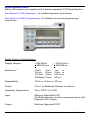
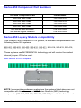
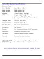
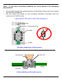
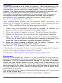
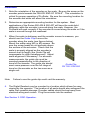
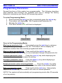
ProScale® 950 Series User Manual for Models 950-404, 950-405, 950-406, 950-407 with DRO Firmware V2.0 or higher WARRANTY Accurate Technology , (ATI) warrants this product against defective parts and workmanship for one year, commencing from the date of original purchase. Upon notification of a defect, ATI shall have the option to repair or replace any defective part. Such services shall be the customer's sole and exclusive remedy. Expenses incidental to repair, maintenance, or replacement under warranty, including those for labor and material, shall be borne by ATI. Except as expressly provided in this warranty, ATI., does not make any warranties in respect to the product, either expressed or implied, including implied warranties of merchantability or fitness for a particular purpose, except as expressly provided in this agreement. ATI shall not be liable for any special, incidental, or consequential damages or for loss, damage or expense directly or indirectly arising from the customer's use of or inability to use the equipment either separately or in combination with other equipment, or for personal injury or loss or destruction of other property, or from any other cause. SAFETY WARNING If installing this measuring system on machinery, turn off the machine and disconnect it from its power source to avoid potential injury. Manual Part Number 800-1024-002 Rev D Copyright 2009 All rights reserved. Accurate Technology. - ProScale Series 950 2 of 40 Table of Contents SECTION 1 GENERAL INFORMATION .................................................. 5 INTRODUCTION .............................................................................................. 5 W HAT THIS MANUAL INCLUDES ....................................................................... 5 SERIES 950 ABS TERMINOLOGY ..................................................................... 6 Scale ....................................................................................................... 6 Encoder ................................................................................................... 7 Digital Readout (DRO) ............................................................................. 8 SERIES 950 COMPONENT PART NUMBERS ....................................................... 9 SERIES 950 LEGACY MODELS COMPATIBILITY ................................................... 9 SERIES 950 SYSTEM SPECIFICATIONS ............................................................10 SECTION 2 INSTALLATION ................................................................11 MODELS 950-404 AND 950-405.....................................................................11 Installation...............................................................................................11 Calibration...............................................................................................14 Maintenance ...........................................................................................14 MODELS 950-406 AND 950-407.....................................................................15 Installation...............................................................................................16 Calibration...............................................................................................18 Maintenance ...........................................................................................18 SECTION 3 DRO OPERATION .............................................................19 THE LCD.....................................................................................................19 BASIC KEYS .................................................................................................19 Key Timing..............................................................................................19 ON/OFF ..................................................................................................20 UNITS.....................................................................................................21 PLUS (+) & MINUS (–) ............................................................................22 DATUM...................................................................................................22 BASIC FUNCTIONS ........................................................................................23 Measurement Reading Direction .............................................................23 Segment Offset Adjustment.....................................................................23 Lock Mode ..............................................................................................23 Resolution...............................................................................................24 Measurement Units .................................................................................24 ADVANCED KEYS ..........................................................................................25 ABS - INC ...............................................................................................25 MON .......................................................................................................25 HOLD .....................................................................................................26 SEND .....................................................................................................27 F1 / F2 ....................................................................................................27 ADVANCED FUNCTIONS .................................................................................28 Linear Scaling .........................................................................................28 Manual Part # 800-1024-002, Rev D, Effective 7-1-2009 3 of 40 Offset Addition ........................................................................................28 Upper/Lower Limits .................................................................................28 SECTION 4 DRO PROGRAMMING .......................................................29 PROGRAMMING PARAMETERS ........................................................................29 Pr0 Measurement Direction....................................................................30 Pr1 Enable/Disable Segment Offset .......................................................30 Pr2 High Speed Readhead Operation ....................................................30 Pr3 Enable/Disable the +, - and Datum keys...........................................30 Pr4 Readout Resolution .........................................................................30 Pr5 Metric Display Units .........................................................................30 Pr6 Disable Fractions/Inches..................................................................31 Pr7 Scaling Factor..................................................................................31 Pr8 Automatic Power Off ........................................................................31 Pr9 Auxiliary Keys Enable ......................................................................31 Pr10 Offset Addition Enable ....................................................................31 Pr11 Offset Addition # 2 ..........................................................................31 Pr12 Offset Addition # 3 ..........................................................................32 Pr13 Offset Addition # 4 ..........................................................................32 Pr14 Limits Function Enable....................................................................32 Pr16 Lower Limit .....................................................................................32 Pr17 – Upper Limit ..................................................................................32 Pr18 Drift Tolerance ................................................................................32 Pr19 Automatic MONITOR ON time ........................................................32 Pr20 Auto MONITOR OFF Enable...........................................................33 Pr21 Auto MONITOR OFF Distance........................................................33 DRO JUMPERS ............................................................................................34 SECTION 5 MISCELLANEOUS.............................................................35 CHANGING THE BATTERIES ............................................................................35 COMMUNICATING W ITH OTHER EQUIPMENT .....................................................36 ABBE ERROR ...............................................................................................37 FREQUENTLY ASKED QUESTIONS ...................................................................38 SECTION 6 ACCESSORIES.................................................................39 PRORF SPC................................................................................................39 PRORF ENCODER ........................................................................................39 PROMUX ....................................................................................................39 ANALOG INTERFACE UNIT ..............................................................................39 VDRO™ .....................................................................................................39 PRODUCT REGISTRATION..........................................................................40 Accurate Technology. - ProScale Series 950 4 of 40 SECTION 1 GENERAL INFORMATION Introduction The ProScale Series 950 digital measuring systems are affordable, battery operated devices for making linear measurements with speed and accuracy. Each system consists of a scale, an encoder and a digital readout (DRO). ProScale Models 950-404, 950-405, 950-406 and 950-407 use Absolute Capacitive measuring technology. The 950 Series Encoders & Digital Readouts use Mitutoyo style 10 pin connectors and the Readout is branded with the Mitutoyo name. The Series 950 systems are ideal for most measuring requirements up to 6m (20ft.) where high accuracy, (better than 10 µm) is not needed, but affordable repeatability, portability, and accuracy to 50 µm is desired. They can be used for any general purpose measurement application where SPC data is collected and/or digital accuracy and repeatability is desired. It is also suitable for retrofitting, or as original equipment, on most types of machinery. What This Manual Includes This manual includes installation and operation information for: • • ProScale ABS Series 950-404, 950-405, 950-406 & 950-407 measurement systems, supplied with LCD Digital Readout with Firmware V2.0 or higher. This manual is effective for all systems manufactured after October 1, 2008 Manual Part # 800-1024-002, Rev D, Effective 7-1-2009 5 of 40 Series 950 ABS Terminology All Series 950 ABS linear measuring systems consist of a SCALE, an ENCODER, and a DIGITAL READOUT, (DRO) Scale The ABS scale consists of a series of conductive patterns bonded to an aluminum extrusion. The measuring system determines its actual position by reading a pattern which is unique at any given location over its length. The maximum length of a scale pattern is 430mm (16.932 in.). The pattern must then repeat. Consider the illustration above to represent a Model 950-406 or 407. There are multiple absolute patterns (each pattern is 430mm long), joined together end to end. Within each pattern the system is totally absolute. However, crossing over a pattern joint now presents the encoder with information identical to what it read in the previous pattern. At this point the system must be able to recognize that it has crossed over a pattern joint and therefore must add or subtract the value of 1 pattern offset - 430mm. In fact, each time the encoder passes over a pattern joint it must keep track of how many patterns it has passed, and in which direction. This action is accomplished by the digital readout firmware. If the encoder remains on the same absolute segment, it can have power removed, its position changed and power restored without loss of position information. However, if power is removed and the encoder passes over a pattern joint, the transition will not be recognized. When power is restored the system knows its absolute position on the new pattern, but does not know how many patterns it has passed, or in which direction! Series 950 DROs provide the operator with a method to adjust the pattern offset so the system displays the correct reading at all times without loss of accuracy. See Section 3: DRO Operation; Segment Offset Adjustment All Series 950 ABS scales have a “zigzag” pattern. On longer scales there will be a pattern “break” every 430mm (17in.). To shorten Series 950 ABS scales see: www.proscale.com/other/ABSscalecut.htm. Accurate Technology. - ProScale Series 950 6 of 40 Encoder The ABS encoder, contains a custom computer chip, which transmits and receives signals to and from the scale using capacitive coupling. The signal is used by the encoder to calculate its position to within 10 microns (10µm / .0004in). This position data is then sent to the digital readout, where it can be displayed in millimeters, centimeters, inches, or fractions and sent to an external data acquisition device via a 10 pin SPC connector. All Series 950 ABS encoders have “BLACK END OF SCALE” labels on the cover. All Series 950 ABS scales will have one end painted black. This relationship is important, since the encoder will work, but produce erratic results if installed incorrectly. To insure proper operation, be sure the arrow on the encoder is pointing toward the BLACK end of the scale. The ABS encoder has a 2m (6 ft.) cable Manual Part # 800-1024-002, Rev D, Effective 7-1-2009 7 of 40 Digital Readout (DRO) Series 950 systems are supplied with a battery operated LCD Digital Readout. See Section 3: DRO Operation - for detailed operation instructions. See Section 4: DRO Programming - for detailed set-up and programming instructions. Digital Readout Specifications: Display Ranges: + 999.999 in + 9999.99 mm + 399 63/64 in + 999.999 cm Resolution:* .1inch .1mm .01inch .01mm .001inch .01mm .0005inch .01mm .1cm or .01cm or .001cm or .001cm Repeatability: .001in or .01mm or .001cm Power: 2 AA 1.5v Batteries (Alkaline or Lithium) Operating Temperature: 32 to 120°F, 0 to 50°C Input: Mitutoyo Digimatic® SPC (ProScale encoder or other measuring device with Digimatic SPC output) Output: Mitutoyo Digimatic® SPC Accurate Technology. - ProScale Series 950 8 of 40 Series 950 Component Part Numbers 950 ABS Component Part 950-404 ABS Scale Part Number 700-1500-010 950-405 ABS Scale 700-1500-018 950-406 ABS Scale 700-2500-052 950-407 ABS Scale 950 Series ABS Encoder 700-2500-096 708-1500-M80 950 Series Digital Readout 708-1600-M50 Series 950 Legacy Models compatibility This Readout, with Firmware v2.0 or greater, is backward compatible with the following Series 950 systems: 950-401, 950-402, 950-403, 950-410, 950-411, 950-414, 950-415, 950-416, 950-417, 950-419, 950-421, 950-422, 950-423 These systems use INCREMENTAL technology and will require the readout internal jumper JP2 to be reset. See Section 4 DRO Jumpers Incremental Scale Incremental Encoder NOTE: Incremental encoders or scales from the systems listed above are not compatible with the other current 950 Series Absolute (ABS) technology components (950-404, 950-405, 950-406, 950-407) described in this manual. Manual Part # 800-1024-002, Rev D, Effective 7-1-2009 9 of 40 Series 950 System Specifications Measuring Range: * Model Model Model Model 950-404 950-405 950-406 950-407 Up to 250mm Up to 450mm Up to 1200mm Up to 2400mm (10in) (18in) (4ft) (8ft) Accuracy: (All Models) + (.025 + .064 x L / 430) mm; (max error + 0.20mm @ 1.3 to 6m) + (.001 + .0025 x L / 17) in; (max error + .008in @ 4 to 20 feet) (L = length of measurement in mm or inches) Operating Temp: 0 to 51°C; 32 to 120°F Temp Coefficient: 25ppm/°C; 13ppm/ °F Max. Slew Rate: 400 mm/sec. (15 inches/sec.) Accessories: See Section 6 Encoder: 2m, 10-conductor Mitutoyo 936937 termination. Dimensions: Available at www.mitutoyo.com. US Patents: 4420754, 4879508, 4878013, 4959615 Warranty: One year from date of purchase. * MEASUREMENT range is approximately 100mm (4in) shorter than PHYSICAL length. All ProScale Series 950 products are MADE IN USA Accurate Technology. - ProScale Series 950 10 of 40 SECTION 2 INSTALLATION Models 950-404 and 950-405 Series 950-404 and 950-405 are general purpose measuring systems with standard measuring ranges of 250mm and 450mm respectfully. Models 950-404 & 950-405 systems use ABS style scales, ABS style encoders, and general-purpose digital readouts. Neither the scale nor encoder are compatible with older Mitutoyo Incremental technology systems (950-401, 950402, 950-403, 950-410, 950-411, 950-414, 950-415, 950-416, 950-417, 950419, 950-421, 950-422, 950-423). However the readout is backward compatible and may be used as a direct replacement on older systems. Models 950-404 & 950-405 are easy to install. By following the basics of good installation, reliable, error-free operation can be expected. These systems can be used in many different measurement applications, and with numerous types and brands of equipment. Therefore all installations will be a little different and it is the responsibility of the installer to choose the bolts, screws, or other mounting hardware that guarantee proper installation for optimum operation. Installation 1. Note the orientation of the encoder on the scale. Be sure the arrow on the encoder points towards the “BLACK END OF SCALE”. This orientation is critical for proper operation of ProScale. Be sure the mounting location for the encoder and scale will allow this orientation. 2. Determine an appropriate mounting location for the system. Most applications of the Models 404 & 405 will have the encoder held stationary Manual Part # 800-1024-002, Rev D, Effective 7-1-2009 11 of 40 while the scale is passed through it. The system will still operate properly however if the encoder is moved and the scale is held stationary. 3. If the encoder is to be mounted stationary, the scale should be attached to a moving part of the measuring application or machine using the included Connector Link. Mount the encoder using three screws or bolts. Mount one end of the connector link to the scale using an M5 (or 10-32) screw and the other end to the moving part. Check that the scale is properly aligned with the direction of motion of the moving part. Be sure both connections are secure or inaccurate/erratic readings could result. (The connector link compensates for small misalignments of the installation and acts Connector Link as a shear pin). The connector link must be PN 100-1025-005 mounted in the same direction as the scale (see figure below). Note: Failure to use the connector link could void the warranty. 4. If you choose to hold the scale stationary and move the encoder to measure, you should use the included Guide Clip to move the encoder along the scale (see figure on next page). The connector link is not necessary in this configuration. Mount the scale using a M5 (or 10-32) screw. Be sure the scale is properly aligned as the encoder is moved (the Guide Clip will compensate for slight misalignment in one direction only). Adjust scale alignment if necessary. For accurate measurements, the guide clip must be mounted perpendicular to the Guide Clip direction of travel of the encoder. The guide clip PN 100-1026-005 should exert some pressure over the full range of travel on the encoder so the two move as a single unit. Note: Failure to use the guide clip could void the warranty. 5. The Digital Readout may be mounted in a location which allows for easy viewing by the operator. The location of all parts should also safeguard the cable from possible damage. Encoder cables should be kept away from electrical wiring and motors. Plug the encoder into the readout. See Section 3: DRO Operation. Accurate Technology. - ProScale Series 950 12 of 40 Note: If any other mounting methods are used, observe the following precautions:: • • Do not drill through the colored portion of the Scale at any point over which the Encoder will travel. Do not mount the Scale so the mounting hardware interferes with the movement of the Encoder. Typical Model 950-404 or 950-405 Installations Moving Part Connector Link Encoder Scale Encoder stationary, Scale moves Moving part Guide Clip Scale Encoder Scale stationary, Encoder moves Manual Part # 800-1024-002, Rev D, Effective 7-1-2009 13 of 40 Calibration The accuracy is passive on all Series 950 systems. That is the accuracy of the system depends on the accuracy of the printed pattern on the Scale and the manufacturing process used to join longer lengths of these scale patterns together. The system accuracy is measured at the output of the encoder, and there are no adjustments that can be made to alter this accuracy. The quality of installation and application of the systems within a measuring environment can also affect the overall system accuracy one can expect. See Section 3: DRO Operation; Advanced Functions; Linear Scaling See Section 5: Miscellaneous; Abbe Error Once installed these systems can be calibrated quickly and easily. The following is an example for calibrating a Series 950 on an industrial wide belt sander. Other installations follow the same general procedure. 1. Check to be sure installation of all parts is complete, all fasteners are secure, and the encoder is plugged into the digital readout. 2. Set-up the machine to operate as normal. Run a part through the sander. 3. Measure the thickness of the sanded part with digital calipers if possible. 4. Press the DATUM key on the digital readout then press and hold the + (PLUS) key to scroll until the thickness just measured is displayed (The longer the + key is held down, the faster the readout will scroll). 5. When the correct reading is reached, lock the display if desired. prevents accidentally re-zeroing of the display. See Section 3: DRO Operation; Basic Functions; Lock Mode This If the direction of movement (+ and -) on the readout is opposite the desired direction, the readout programming should be changed. See Section 4: DRO Programming; Programming Parameters; Pr0 Maintenance Although these systems will operate in a dry environment of non-conductive debris such as sawdust, the system should be cleaned of excess debris when necessary. This will prevent premature damage to the scale or encoder. Should the scale become difficult to move, check to see if debris has built up under the encoder and remove if necessary. Remove any burrs which may have developed on the scale. Do not use any liquid lubricants on the scale, as this may impede the encoder’s ability to operate properly and will attract other contaminants to the scale. The readout should be cleaned periodically with compressed air to remove any dust on the lens and keys. All mounting fasteners should be checked occasionally for tightness. Accurate Technology. - ProScale Series 950 14 of 40 Models 950-406 and 950-407 Series 950-406 and 950-407 are general purpose measuring systems with standard measuring ranges of 1.2m and 2.4m respectfully. Models 950-406 and 950-407 systems use ABS style scales, ABS style encoders, and general-purpose digital readouts. Neither the scale nor encoder are compatible with older Mitutoyo Incremental technology systems (950-401, 950-402, 950-403, 950-410, 950-411, 950-414, 950-415, 950-416, 950-417, 950-419, 950-421, 950-422, 950-423). However the readout is backward compatible and may be used as a direct replacement on older systems. Models 950-406 & 950-407 are easy to install. By following the basics of good installation, reliable, error-free operation can be expected. ProScale can be used in many different measurement applications, and with numerous types and brands of equipment. Therefore all installations will be a little different and it is the responsibility of the installer to choose the bolts, screws, or other mounting hardware that guarantee proper installation for optimum operation Manual Part # 800-1024-002, Rev D, Effective 7-1-2009 15 of 40 Installation 1. Note the orientation of the encoder on the scale. Be sure the arrow on the encoder points towards the “BLACK END OF SCALE”. This orientation is critical for proper operation of ProScale. Be sure the mounting location for the encoder and scale will allow this orientation. 2. Determine an appropriate mounting location for the system. Most applications of the Series 950-406 & 950-407 will have the scale held stationary while the encoder is moved along the scale. However, the ProScale will read correctly if the encoder is moved along the scale or if the scale is moved through the readhead. 3. When the scale is stationary and the encoder moves to measure, you should use the Guide Clip to move the encoder along the scale (see figures below). Mount the scale using M4 (or #8) screws. Be sure the screw heads do not protrude above the surface of the extrusion. Check that the scale is properly aligned as the encoder is moved over its length (the Guide Clip will compensate for slight misalignment). Adjust scale alignment if necessary. For accurate measurements, the guide clip must be mounted perpendicular to the direction of travel of the encoder. The guide clip should Guide Clip exert some pressure over the full range of PN 100-1026-005 travel on the encoder so the two move as a single unit. Note: Failure to use the guide clip could void the warranty. 4. The Digital Readout may be mounted in a location which allows for easy viewing by the operator. The location of all parts should also safeguard the cable from possible damage. Encoder cables should be kept away from electrical wiring and motors. Plug the encoder into the readout. See Section 3: DRO Operation. Accurate Technology. - ProScale Series 950 16 of 40 M o v in g P a r t G u i d e C l ip E n co de r S c ale G u id e C li p E ncod er 2 1 .2 m m (.8 3 ") S ca le 3 3 .0 m m ( 1 .3 " ) Guide Clip Pressure/Spacing (End View) Typical Model 950-406 or 950-407 Installation Manual Part # 800-1024-002, Rev D, Effective 7-1-2009 17 of 40 Calibration The accuracy is passive on all Series 950 systems. That is the accuracy of the system depends on the accuracy of the printed pattern on the Scale and the manufacturing process used to join longer lengths of these scale patterns together. The system accuracy is measured at the output of the encoder, and there are no adjustments that can be made to alter this accuracy. The quality of installation and application of the systems within a measuring environment can also affect the overall system accuracy one can expect. See Section 3: DRO Operation; Advanced Functions; Linear Scaling See Section 5: Miscellaneous; Abbe Error Once installed, the system can be calibrated easily and quickly. The following is an example for calibrating a system on a table saw fence. Other installations follow the same general procedure. 1. Check to be sure installation of all parts is complete, all fasteners are secure, and the encoder is plugged into the digital readout. 2. Cut a part using the normal fence operation. 3. Do not move fence until calibration is completed. 4. Measure the dimension of the part with digital calipers. 5. Press the DATUM key on the readout and then press and hold the + PLUS key to scroll until the caliper measurement you just made is displayed. (The longer the +key is held down, the faster the display will scroll). 6. When the correct reading is reached, lock the readout if desired. This prevents accidentally re-zeroing of the readout. See Section 3: DRO Operation; Basic Functions; Lock Mode If the direction of movement (+ and -) on the readout is opposite the desired direction, the readout programming should be changed. See Section 4: DRO Programming; Programming Parameters; Pr0 Maintenance Although these systems will operate in a dry environment of non-conductive debris such as sawdust, the system should be cleaned of excess debris when necessary. This will prevent premature damage to the scale or encoder. Should the scale become difficult to move, check to see if debris has built up under the encoder and remove if necessary. Remove any burrs which may have developed on the scale. Do not use any liquid lubricants on the scale, as this may impede the encoder’s ability to operate properly and will attract other contaminants to the scale. The readout should be cleaned periodically with compressed air to remove any dust on the lens and keys. All mounting fasteners should be checked occasionally for tightness. Accurate Technology. - ProScale Series 950 18 of 40 SECTION 3 DRO OPERATION This section covers the operation of the Series 950 LCD Digital Readout (DRO) (Firmware V2.0 and higher). This readout is supplied on all ProScale 950 Series Digital Measuring Systems. (Readout firmware version is displayed on power-up, ie P2.000) P2.000 The LCD The above figure illustrates all the segments available on the Digital Readout. Pressing and holding the ON/ OFF and UNITS key for 10 seconds while the readout is turned off will perform a full segment LCD test. CAUTION: This will reset all programming parameters to factory defaults. Basic Keys Key Timing The keys pictured above, found on all Series 950 Readouts, have multiple functions. Timing, which is how long a key is depressed, and the combination of the keys pressed is important. This manual uses the term ‘”momentarily” to describe a key press of shorter than 1 second. Whereas the term “press and hold” is used to describe a key press of longer than 1.5 seconds. As an example; when using a PC keyboard to type a capital letter you would “press and hold” the SHIFT key and “momentarily depress the LETTER key. In addition most of the key “functions” are executed on RELEASE, not press. This is important since some of the same keys execute different functions based on how long they are pressed and when they are released. These key operations, once tried, quickly become intuitive. See Table on next page:. Manual Part # 800-1024-002, Rev D, Effective 7-1-2009 19 of 40 Momentarily Press & Hold How long a key is pressed? Less than 1 second More than 1.5 second When is key function executed? On key release While holding Functions executed on key release for momentary key presses and functions executed after the allotted time has elapsed for press & hold operations are shown below. Key Press & Hold (in programming mode) Momentarily Press Cycles measurement units: inches, fractions, mm Increments program parameter list Plus (+) (in programming mode) increments displayed value increments parameter value increments faster increments faster (in programming mode) forces reading to programmed datum value forces parameter to factory default After 6 seconds: battery voltage After 9 seconds: Temperature no effect Minus (-) (in programming mode) decrements displayed value decrements parameter value decrements faster decrements faster UNITS DATUM No effect Displays Pr # The readout’s basic operation keys and their functions are described below, and where applicable include references to the Programming Parameters effecting their operation. See Section 4: DRO Programming; for additional information. ON/OFF Momentarily press or Press and Hold Momentarily pressing the ON/OFF key will cause the readout to turn on or off. The Firmware Version will be displayed on power-up. While on, if no key presses or positional changes occur within 15 minutes, the readout will automatically turn itself off to conserve battery life. While off, if a position Accurate Technology. - ProScale Series 950 20 of 40 change is detected (.05mm or .002in) or the ON/OFF key is pressed, the readout will automatically turn itself on with no loss of measurement information. See Section 4: DRO Programming, Programming Parameter Pr8. Pressing and holding the ON/ OFF key for 5 seconds while the readout is turned on will display the battery voltage. Pressing and holding the ON/ OFF and UNITS key for 10 seconds while the readout is turned off will perform a full segment LCD test. CAUTION: This will reset all programming parameters to factory defaults. UNITS The readout can display measurement information in Imperial or Metric units. To change the readout mode, momentarily press the UNITS key. With each key press the readout will cycle through decimal inches, fractional inches (1/16), (1/32), (1/64) and metric. See Section 4: DRO Programming, Programming Parameter Pr5. See Section 4: DRO Programming, Programming Parameter Pr6. Momentarily press When the readout is in 1/16 or 1/32 inch fraction mode, a series of “bars” in the upper right corner of the display, each representing 1/64th of an inch, may appear. (ie. When in 1/16 inch mode and three bars are showing, the measurement displayed is rounded down to the closest 1/16 inch and each illuminated bar indicates an additional 1/64 of an inch of measurement.) For better resolution, switch to 1/32 or 1/64 mode. For the best resolution and accuracy switch to a decimal mode. When the measurement is greater than 99 63/64 inches, a +100 and/or +200 will illuminate in the upper right portion of the display to indicate this amount must be added to the displayed reading. ie: If the measurement is 154 5/8 inches, 54 5/8 and +100 will be illuminated on the display. If the measurement is -307 23/64 inches, - 7 23/64, +100 and +200 will be illuminated on the display. Manual Part # 800-1024-002, Rev D, Effective 7-1-2009 21 of 40 PLUS (+) & MINUS (–) Momentarily or Press & Hold Momentarily pressing the + or – key increments or decrements the current displayed value by one unit of measurement. Pressing and holding the + or – key will cause the displayed value to change continuously. Continue pressing the key to cause the amount of change to speed up. This allows for quick adjustments over a large range of values. These keys may be locked out to prevent accidental offset entries by seting the readout to LOCK mode or by programming. See Section 3: DRO Operation; Basic Functions; Lock Mode See Section 4: DRO Programming, Programming Parameter Pr3. DATUM Momentarily press The DATUM key is used to change the currently displayed value on the readout. Momentarily press the DATUM key to force the readout to a user programmed value. While in most cases this would be zero, it can be programmed to any other displayable value. See Section 4: DRO Programming, Programming Parameter Pr2. The DATUM key can also be locked out from front panel operation to prevent accidental key presses by setting the readout to LOCK mode or by programming. See Section 3: DRO Operation; Basic Functions; Lock Mode See Section 4: DRO Programming, Programming Parameter Pr3. Accurate Technology. - ProScale Series 950 22 of 40 Basic Functions Measurement Reading Direction Once the system has been put into operation, if the direction of readings, (positive or negative values) is opposite the desired direction, the readout programming may be changed to correct the direction. See Section 4: DRO Programming, Programming Parameter Pr0. Segment Offset Adjustment For scales that are longer than 430mm (17 inches), multiple scale pattern segments are installed end-to-end on the aluminum extrusion. This provides a quasi-absolute measurement capability in which the readout can calculate its position on any individual scale segment but cannot determine which particular segment it is on. To solve this problem, the readout software tracks which scale segment the encoder is on by detecting the “splice” between one segment and adjacent segments. In certain situations, the crossing from one segment to another may not be detected by the readout. This may occur if the encoder is disconnected from the readout and then moved along the scale to another segment. It may also occur if the encoder is moved too quickly between two segments. (Maximum slew rate is 400mm/sec, 15in/sec) If the segment tracking count is incorrect because of one of the above situations, the user can re-adjust the display to correct the error. This adjustment is referred to as the Segment Offset Adjustment. To add one segment value (430.08mm) to the displayed value, hold the UNITS key and then momentarily press the + key. The displayed position will increase by 430.08mm (16.933 inches). To subtract one encoder segment from the displayed value, press and hold the UNITS key and then momentarily press the – key. The displayed position will decrease by 430.08mm. See Section 1: General Information; Series 950 Terminology See Section 4: DRO Programming, Programming Parameter Pr1. Lock Mode Press and hold the ON/OFF key and then momentarily press the UNITS key to activate the Lock function, The word LOCK will appear in the upper left corner of the readout. When the LOCK symbol is displayed, the +, DATUM and – keys become inactive to prevent accidental changes of the current displayed value. To de-activate the Lock function, press and hold the ON/ OFF key and then momentarily press the UNITS key. NOTE: The Lock function can also be enabled/disabled through programming. This allows a more permanent Lock function since programming can be disabled with a hardware jumper inside the readout thus preventing any front panel programming changes. See Section 4: DRO Programming, Programming Parameter Pr3. See Section 4: DRO Programming, DRO Jumpers Manual Part # 800-1024-002, Rev D, Effective 7-1-2009 23 of 40 Resolution Three display resolutions are available. Reduced .01in .01mm or .01cm Normal .001in .01mm or .001cmr Increased .0005in .01mm or .001cm Fractional displays of 1/16, 1/32 and 1/64 are not effected by resolution programming changes. Auto scaling will allow measurements of over 100 inches when in high resolution. Measurements over 100 inches will automatically be reduced to 3 decimal places See Section 4: DRO Programming, Programming Parameter Pr4. When the readout is in a decimal mode (mm, cm or in) it will auto-range to the next resolution if the value is displayable in the next range. This allows the display to be used with other Mitutoyo products with SPC in inch mode or different resolutions other than 2 decimal places. Measurement Units The measurement units displayed on the Readout when the UNITS key is depressed is user configurable. The table below provides a matrix for selecting which units will be displayed (based on the value entered in programming parameter). See Section 4: DRO Programming, Programming Parameter Pr5. See Section 4: DRO Programming, Programming Parameter Pr6. Programming Parameter Pr 5 value 0 1 Programming Parameter Pr 6 value 0 1 2 Measurement Units Displayed Millimeters (in metric mode) Centimeters (in metric mode) All inch units plus mm or cm based on Pr5 NO fractions, decimal inches, mm or cm NO inches, mm or cm ONLY based on Pr5 Accurate Technology. - ProScale Series 950 24 of 40 Advanced Keys ABS - INC The readout has two measurement modes, or indexes. One is referred to as ABS or Absolute, and the other as INC or Incremental. The ABS measurement mode allows the user to set a current position on the readout referenced from a fixed or known position such as a fixed stop, saw blade, or other absolute point. The INC mode makes relative distance measurements from one arbitrary point to another. The modes operate independently allowing multiple incremental offsets to be programmed. The absolute position of the measuring system is not lost when using the INC mode. ABS The readout automatically enters ABS mode when power is first applied. This is indicated by the ABS symbol in the upper left corner of the display. While in the ABS mode, all position measurements are related to the current ABS, or absolute system reference point. To enter the INC mode, momentarily press the ABS/INC key. INC While in the INC mode, the INC symbol is shown in the upper left corner of the readout. When the INC mode is initially entered, the displayed position will change to reflect a new reference point at the current position of the encoder. This is typically a position of zero (0) but may be changed by using the + or keys to provide an offset. Moving the encoder in either direction will display the distance moved from the initial INC starting point (plus any offset). To complete another incremental measurement from the new position, momentarily press the ABS/INC key. The readout will again change to 0 (or the previously programmed offset). To return to the ABS mode, press and hold the ABS/INC key for approximately 4 seconds. MON The readout can monitor a position to detect position drift or measurement variance. The readout can be programmed to enter the MONITOR mode manually or based on elapsed time. Manual activation: With programming parameter Pr19 set to 0 (activate on movement), position the encoder to the desired location and then momentarily press the MON key. The MON symbol will flash on the readout to indicate the Manual Part # 800-1024-002, Rev D, Effective 7-1-2009 25 of 40 MONITOR mode is active. While active, any encoder movement that exceeds the user programmed (Pr18) drift tolerance will cause the measured reading to flash, indicating a drift condition. When the encoder is moved back to within the programmed tolerance window, the reading will stop flashing. To exit the MONITOR mode, momentarily press the MON key again. The MON symbol will extinguish and the currently displayed position will also stop flashing. Automatic activation With programming parameter Pr19 set to 1 or 2 (activate after 30 or 60 seconds) the MONITOR mode will automatically become active after the selected amount of time allowing for settling- no encoder movement- of the measurement system before activating the MONITOR function. Once activated, any encoder movement that exceeds the user programmed (Pr18) drift tolerance window, will cause the reading to flash, indicating a drift condition. When the encoder is moved back to within the programmed tolerance window, the reading will stop flashing. Automatic De-activation The readout can also be programmed (Pr20) to automatically exit the MONITOR mode based on additional movement (Pr21) of the encoder outside the programmed drift tolerance. This option, in conjunction with automatic activation, allows the ProScale to be kept in MONITOR mode without manually pressing the monitor key. NOTE: MONITOR mode can only be activated in the ABS measuring mode. If the ABS/INC key is depressed while monitoring, the MONITOR mode is automatically exited. See Section 4: DRO Programming; Programming Parameters Pr18, Pr19, Pr20, Pr21 HOLD The readout provides a feature that allows the displayed position to be “frozen” in time while the encoder is moved from its measuring position. This allows measurements to be captured on the readout and held for later viewing regardless of the current encoder position. To activate the HOLD mode, momentarily press the HOLD key. The HOLD symbol will be shown in the upper left corner of the readout. The currently displayed position and selected key presses will be frozen at this point. To release the HOLD feature, momentarily press the HOLD key again. Accurate Technology. - ProScale Series 950 26 of 40 SEND The readout provides an output port that can be used to send measurement information to a compatible SPC device such as a printer or data acquisition unit. After connecting the SPC device to the 10 pin connector on the readout, the user may initiate the data transmission by momentarily pressing the SEND key. This signals the SPC device to acquire the data from the readout. Pressing the SEND key displays “ Snd ” on the readout for 1 second to show activation of the send function (even if no SPC device is attached to the readout). The data format and connector style of the SPC output is the same (Mitutoyo Digimatic® SPC) as other Mitutoyo products and can be interfaced with most available SPC products including multiplexers, USB/RS232 converters and wireless data transmitters. Data from the readout is sent to the SPC connector in either millimeters or decimal inches, whichever is currently displayed on the readout. If no SPC device is attached to the readout, the SEND key has no other function. See Section 6 Accessories: For interface and data acquisition products. F1 / F2 These keys are used for Advanced DRO Functions and/or Custom programming functions. Manual Part # 800-1024-002, Rev D, Effective 7-1-2009 27 of 40 Advanced Functions Linear Scaling 950 Series Readouts have the ability to “scale” the actual measurement. This function is useful for linear compensation of the Series 950 measuring system or when the actual measurement must be multiplied or divided before being displayed. Care should be taken when using this function since invoking it will cause the system to display a reading other than the actual measured value. This function has a range of: 0.001 to 99.999 allowing the actual measured value to be multiplied or divided in very small or very large increments. See Section 4: DRO Programming; Programming Parameter Pr7 Offset Addition Offset addition allows values to be pre-programmed that are then added to the measurement and the result displayed on the readout. This function allows a user to quickly switch from one reference point to another. The 950 Series DRO can support 3 user definable offsets that can be added to the current ABS position. Programming Parameter PR10 enables or disables this function. Programming parameters PR11 - 13 set the offset values. When Offset Addition is enabled, the operator scrolls through the programmed offsets by pressing the F1 key. The numbers 1, 2, 3, 4 will be displayed in the upper left corner of the readout with each press of F1. When the number 1 is displayed on the readout, NO Offset is applied and the absolute measurement/position is displayed on the readout. When the number 2 is displayed, Offset Addition Preset #2 (PR11) has been applied to the measurement and the result is now displayed on the readout. When the number 3 is displayed, Offset Addition Preset #3 (PR12) has been applied to the measurement and the result is now displayed on the readout. When the number 4 is displayed, Offset Addition Preset #4 (PR13) has been applied to the measurement and the result is now displayed on the readout. See Section 4: DRO Programming; Programming Parameters, Pr10 - Pr13. Upper/Lower Limits The Upper/Lower Limits function is enabled by setting Programming Parameter PR14 to 1. The Upper and Lower limit values are set with programming parameters PR16 and PR17. When these limits are exceeded the readout will toggle between the current position and LL (or UL) every 2 seconds. This will continue as long as either limit has been exceeded. Limit monitoring is always active, even in programming mode. See Section 4: DRO Programming; Programming Parameters Pr14, Pr16 Pr17 Accurate Technology. - ProScale Series 950 28 of 40 SECTION 4 DRO PROGRAMMING Programming Parameters Several functions of this readout are programmable. The following describes what features and functions are available and how to change the factory defaults to customize your Series 950 measuring system. To enter Programming Mode: 1. 2. 3. 4. Press and hold the UNITS key then momentarily press the DATUM key. The readout will display Pr 1, 1 (Programming Parameter #1) Release the UNITS key The value stored for Pr1 will then be displayed. Press & Hold Momentarily press Once in the Programming Mode: Momentarily press the UNITS key to advance Moving up parameter list through the programming parameter list. The readout will first display the parameter number then the currently programmed value. Moving down parameter list Press and hold the ON/OFF key and momentarily press the UNITS key to move backward through the parameter list. Press the PLUS (+) key while displaying the Increase parameter value current parameter value to increase the setting. Decrease parameter value Press the MINUS (-) key while displaying a current parameter value to decrease the setting. Reset parameter value to factorydefault Press the DATUM key while displaying a current parameter value to reset this value to the factory default. Exit programming mode Press and hold the UNITS key. Momentarily depress the DATUM key. The readout will return to normal operation. NOTE: The readout will automatically exit programming mode after 60 seconds of no key activity. Manual Part # 800-1024-002, Rev D, Effective 7-1-2009 29 of 40 All available Programming Parameters are listed below. Values in [ ] are the available range of values that may be programmed for that parameter. Series 950 factory default values are shown in red. Some programming parameters, including Offset Addition and Limit mode indicate a factory default set in inches. The equivalent value in mm or cm is applied if you switch the readout UNITS to mm or cm. Pr0 Measurement Direction [0, 1] Change this setting to reverse the direction of measurement readings. Pr1 Enable/Disable Segment Offset [0, 1] Set to 0 for Series 950-404 systems and all measuring systems shorter than 430mm (16.9in), plus all legacy 950 series ProScale systems. Set to 1 for series 950-405, 950-406, 950-407 and all ProScale measuring systems longer than 430mm (16.9in). Pr2 High Speed Readhead Operation [0, 1] 0 = Normal Series 950 readhead 1 = Customized Series 950 readheads ONLY (reduces battery life) Pr3 Enable/Disable the +, - and Datum keys [0, 1] This is a programming alternative to the front panel LOCK function. When this parameter is set to 0 the readout’s +, - and DATUM keys are inactive. 0 = Disables the +, - and DATUM keys (readout in LOCK mode). 1 = Enables the +, - and DATUM keys. Pr4 Readout Resolution [0, 1, 2] This sets the decimal resolution of the readout (fractions are unaffected). 0 = Reduced resolution Inch = xxx.xx MM = xx.x 1 = Normal resolution Inch = xxx.xxx MM = xx.xx 2 = Increased resolution Inch = xx.xxxx MM = xx.xx Pr5 Metric Display Units [0, 1] This selects whether readings are displayed in millimeters or centimeters when the readout is in metric mode. 0 = millimeters 1 = centimeters Accurate Technology. - ProScale Series 950 30 of 40 Pr6 Disable Fractions/Inches [0, 1, 2] This parameter controls which measurement units are displayed as the readout’s UNITS key is pressed. 0 = All available measurement units: inches, fractions and metric.* 1 = Disable fractions: Only display decimal inches and metric.* 2 = Metric Only: No decimal inches or fractions will be displayed. * Pr5 will determine if mm or cm are displayed for metric units. Pr7 Scaling Factor [.001 to 99.999] The actual measured value is multiplied by this setting and the result is displayed on the readout. Scaling factors less than 1.000 will make the displayed measurement less that the actual measurement. Scaling factors greater than 1.000 will make the displayed measurement greater than the actual measurement. Default = 1.000 (No Scaling) Pr8 Automatic Power Off [0 to 60] This value represents the amount of time in minutes of no encoder movement before the readout will automatically turn off to conserve battery life. Any encoder motion or press of the ON/OFF key “wake-ups” the readout and resets this timer. Set to 0 to disable this feature and allow the readout to be turned on or off with the ON/ OFF key only. Default = 15 minutes for all 950 series systems. Pr9 Auxiliary Keys Enable [0, 1, 2, 4, 7] This setting allows selective activation of the readout’s advanced keys. 0 = SEND, F1, F2 Enabled 1 = SEND, F1, F2 and ABS/INC Enabled 2 = SEND, F1, F2, and MON Enabled 4 = SEND, F1, F2, and HOLD Enabled 7 = All Keys Enabled Pr10 Offset Addition Enable [0, 1] This setting enables the readout’s Offset Addition Function and enables the F1 key to advance through each preset value. (Pr11, Pr12, Pr13) 0 = Offset Addition Function Disabled, Pr11, Pr12, Pr13 are inactive 1 = Offset Addition Function Enabled, Pr11, Pr12, Pr13 are active Pr11 Offset Addition # 2 [0 to ± 999.999 in] or [0 to ±9999.99 mm] When Offset 2 is selected with the F1 key this value is added to the current ABS position and displayed on the readout. Only active if Pr10 is set to 1. Default = 1.000 in. NOTE: When Offset 1 is selected with the F1 key, the value displayed is the current ABS position with NO Offset applied (normal operation). Manual Part # 800-1024-002, Rev D, Effective 7-1-2009 31 of 40 Pr12 Offset Addition # 3 [0 to ± 999.999 in] or [0 to ±9999.99 mm] When Offset 3 is selected with the F1 key this value is added to the current ABS position and displayed on the readout. Only active if Pr10 is set to 1. Default = 1.500 in. Pr13 Offset Addition # 4 [0 to ± 999.999 in] or [0 to ±9999.99 mm] When Offset 4 is selected with the F1 key this value is added to the current ABS position and displayed on the readout. Only active if Pr10 is set to 1. Default = 2.000 in. Pr14 Limits Function Enable [0, 1] This setting enables the readout’s Upper/Lower Limit Function. The value for the lower limit is set in Pr16 and the upper limit in Pr17 0 = Limits Function is Disabled, Pr16 and Pr17 are inactive 1 – Limits Function is Enabled, Pr16 and Pr17 are Active Pr15 Output for Limits – Polarity Control (not available on Series 950) Pr16 Lower Limit [0 to ± 999.999 in] or [0 to ±9999.99 mm] This parameter sets the Lower limit value for the Limits Function. This setting is active only if Pr14 is set to 1 Default = 0.000 in. Pr17 – Upper Limit [0 to ± 999.999 in] or [0 to ±9999.99 mm] This parameter sets the Upper limit value for the Limits Function. This setting is active only if Pr14 is set to 1 Default = 5.000 in. Pr18 Drift Tolerance [.001 to 999.999in] or [.01 to 9999.99mm] This parameter sets the range of motion allowed by the encoder while the readout is in MONITOR mode. Default = .0100 in Pr19 Automatic MONITOR ON time [0, 1, 2] This parameter configures the readout to automatically activate MONITOR mode after a period of time has elapsed with no encoder movement. 0 = automatic Monitor mode activation disabled. 1 = activate MONITOR mode after 30 seconds of no activity. 2 = activate MONITOR mode after 60 seconds of no activity. Accurate Technology. - ProScale Series 950 32 of 40 Pr20 Auto MONITOR OFF Enable [0, 1] This parameter configures the readout to automatically exit the MONITOR mode after a programmed distance (Pr21) has been exceeded from the drift tolerance position (Pr18). 0 = automatic MONITOR off disabled 1 = automatic MONITOR OFF enabled. Pr21 Auto MONITOR OFF Distance [0.001 to 999.999in] or [0.01 to 9999.99mm] This parameter programs the distance that must be exceeded from the drift tolerance (Pr18) before MONITOR OFF is activated. Only active if programming parameter Pr20 is set to 1 (enabled) Default = 0.500 in Pr22 Backlight Control (not available on Series 950) Pr23 Future Enhancement DO NOT CHANGE [0,1,2] Default =1 Pr24 Future Enhancement DO NOT CHANGE [0..63] Default =0 Pr25 Future Enhancement DO NOT CHANGE [0..31] Default =0 NOTE: Pressing and holding the ON/ OFF and UNITS keys for 10 seconds while the readout is powered off will perform a full segment LCD test and reset all programming parameters to factory defaults. Manual Part # 800-1024-002, Rev D, Effective 7-1-2009 33 of 40 DRO Jumpers In addition to the keyboard-programming to enable and configure features of the system, several jumpers are located on the readout circuit board for additional system configuration. User configurable jumpers consist of three pins and a ‘shorting block’. The center of these pins is ‘Common’. One end pin is labeled ‘A’ and the other end pin is labeled ‘B’. JP4 JP3 JP1 JP1 JP5 JP2 FOR FACTORY USE ONLY JP2 Legacy system compatibility This readout supports both Incremental and Absolute technology measuring systems making it backward compatible with older Mitutoyo 950 Series ProScale digital measuring systems. This readout is configured for use with the absolute encoders used with Series 950-404, 405, 406 and 407 systems (jumper in position A). For older incremental 950 Series systems, install the jumper in position B and set programming parameter Pr1 to 0. JP3 Keyboard Programming Enable/Disable The front panel key programming mode of the 950 series readout can be enabled or disabled with this jumper. To enable front panel key programming (default), install the jumper in position A. To disable front panel key programming, install the jumper in position B. When programming mode is disabled, the user cannot access the programming functions via the UNITS & DATUM keys. This provides a method of configuring the readout with specific parameters and prevents unauthorized configuration changes. JP4 Power Source All Mitutoyo 950 Series DRO’s are battery powered. JP5 DO NOT CHANGE FOR FACTORY USE ONLY Accurate Technology. - ProScale Series 950 34 of 40 SECTION 5 MISCELLANEOUS Changing the Batteries A low battery indicator will appear in the lower left corner of the LCD display when new batteries are needed. To change batteries remove the screws in the upper right and lower left corners. Pull the cover off. Remove the old batteries. Reinstall new AA Alkaline or AA 1.5 V Lithium batteries, noting the proper orientation. Replace the cover and tighten the screws. CAUTION: DO NOT BEND BATTERY CLIPS! THESE CLIPS ARE DESIGNED TO BE LOOSE WHEN THE CASE IS OPEN AND WILL COMPRESS AND SECURE THE BATTERIES IN PLACE WHEN THE CASE HALVES ARE SCREWED TOGETHER. Manual Part # 800-1024-002, Rev D, Effective 7-1-2009 35 of 40 Communicating With Other Equipment The Series 950 digital readouts have an 10 pin SPC output connector adjacent to the 10 pin encoder input connector. The format of this output data is Mitutoyo Digimatic® SPC. There are numerous products available to intercept, convert and redirect this data format in its natural state or as an RS232 or USB data stream. Section 6 of this manual describes several products made specifically for this digital readout and encoder that allow data to be converted and sent in a wired configuration or as wireless data within a 2 way transceiver system capable of monitoring multiple individual digital measuring systems. The Series 950 ProScale measuring systems are also capable of data output directly from the encoder without the use of a readout. This configuration requires the user to also provide power for the encoder. Please contact Accurate Technology for more information about data format, timing charts and pin-out configurations. Accurate Technology. - ProScale Series 950 36 of 40 Abbe Error Abbe error is a condition that may not be visible to the human eye, but will affect the accuracy linear measurements. Be sure to take precautions when installing Series 950 measuring systems to eliminate the possibility for Abbe errors (sometimes referred to as cosine errors). Abbe error refers to a linear error caused by the combination of an angular error and a dimensional offset between the sample and the measuring system. It is important to understand that the information the encoder is providing is only the position of the encoder on the scale. To illustrate this, see the above figure, which shows a linear measuring device. (The apparent distortion in the measuring device is intentional - for this example - to show the measuring device with a curvature in its mounting.) Suppose the curvature in the figure is sufficient to produce an angle of 40 arcseconds. If the measuring device moves 10 inches, the measuring probe will be found to have moved 10.0039 inches, resulting in an error of +0.0039 inches. Abbe error could be lessened by moving the measuring system closer to the sample. This effectively solves one half of the Abbe error problem (offset) and leaves only the angular mounting problem to be solved. Angular error can best be countered through proper design and placement of the linear scale. Sources of angular error include: 1. 2. 3. 4. 5. Mounting the linear scale to an imperfectly flat surface. Mounting the linear scale to an imperfectly straight surface. Curvature of ways (or linear bearings) used to measure the sample. Contaminants between the probe and item being measured. Friction in any part(s) of the measuring device. Manual Part # 800-1024-002, Rev D, Effective 7-1-2009 37 of 40 Frequently Asked Questions What does “no Enc” mean? If the encoder is off the scale, or the encoder cable is unplugged from the readout, “no Enc” will appear on the readout. To clear error: 1. Be sure the encoder is on the scale. 2. Unplug the connector from the readout for one second. 3. Reconnect the encoder cable to the readout. The battery clips seem to be very loose. Is this normal? Yes. DO NOT attempt to bend these clips or wedge anything between them and the case. These clips are designed to expand when the two case halves are screwed together. Can I mount the scale/encoder without the flex link/guide clip? The flex link and guide clip serve to provide an accurate method of transferring the movement of the moving part to the encoder or scale, while also absorbing any stresses that may occur. If they are not used, the warranty could be voided. The readout displays numbers but they seem to be random. Be sure the encoder is oriented correctly on the scale. One end of the scale is black. Be sure that the arrow on the encoder is pointed in the correct direction. The readout does not change as the scale/encoder moves. The readout is in the HOLD mode. Press & release the Hold button. Accurate Technology. - ProScale Series 950 38 of 40 SECTION 6 ACCESSORIES ProRF SPC ProRF allows linear measurement or position data to be transmitted wirelessly to a PC or other device having a USB or RS232 port. The system uses 802.15.4 radio modules to provide reliable two way communication. The transmitter plugs into the Readout SPC output. The system receiver can monitor up to eight individual measuring systems. ProRF Encoder Instead of a long cable* between the encoder and the readout, a transmitter at the encoder sends data to a receiver connected to the readout at a remote location, or to a receiver with RS232 or USB output. The system uses 802.15.4 radio modules to provide reliable two way communication. *May require a different encoder cable. ProMUX ProMUX-3 is an easy to use hardware interface that provides communication from 950 series encoders or readouts to a PC or PLC. ProMUX-3 supports three SPC inputs, and one RS232 output. *May require modified encoder cables Analog Interface Unit The Analog Interface Unit (AIU) is an interface designed to provide an analog signal output proportional to the displayed measurement or position of a Series 950 Series measurement system. It connects directly to the SPC output of the readout and provides a 0-5VDC or 0-10VDC output signal. VDRO™ The Virtual Readout runs on a Windows® PC and provides a real time display of measurement data for one or two axis. It can compare measurements against stored part dimensions, display the amount of error, write the data to a file, read/print bar codes and display an accuracy error distribution histogram. Manual Part # 800-1024-002, Rev D, Effective 7-1-2009 39 of 40 PRODUCT REGISTRATION Fill out for your records and FAX to 1.828.654.8824 or Register on line at www.proscale.com Name E-Mail Company Address Address City State/Region Zip/Postal Code Country Purchased From: Purchased Date: ProScale 950 Serial Numbers: Scale Encoder Readout Accurate Technology. - ProScale Series 950 40 of 40