1
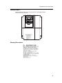
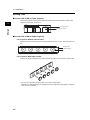
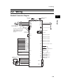
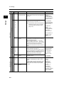
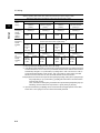
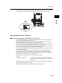
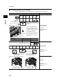
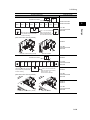
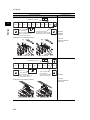
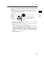
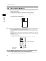
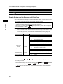
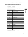
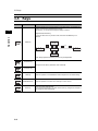
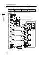
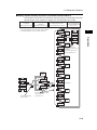
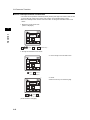
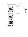
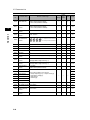
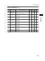
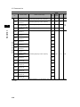
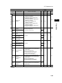
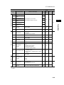
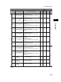
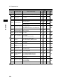
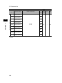
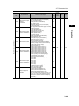
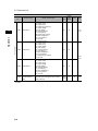
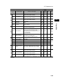
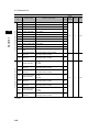
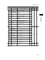
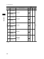
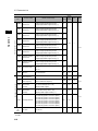
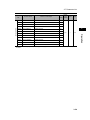
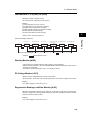
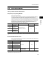
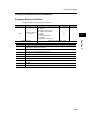
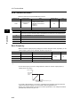
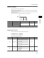
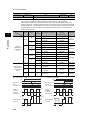
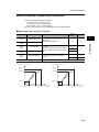
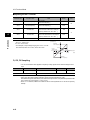
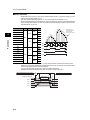
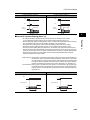
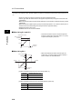
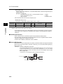
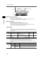
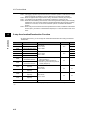
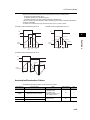
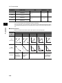
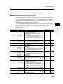
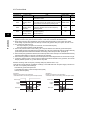
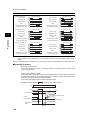
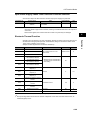
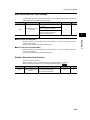
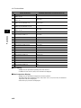
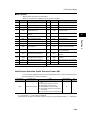
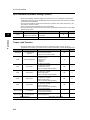
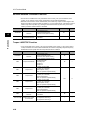
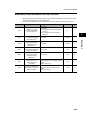
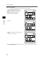
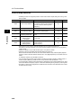
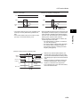
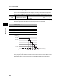
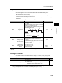
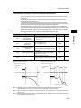
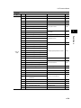
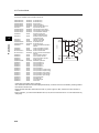
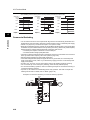
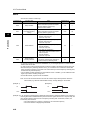
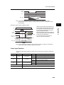
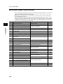
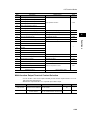
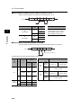
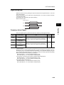
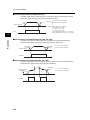
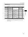
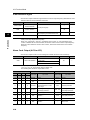
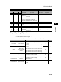
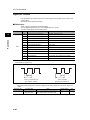
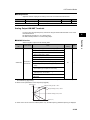
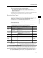
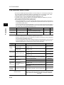
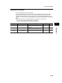
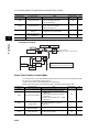
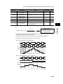
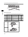
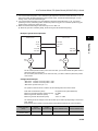
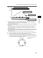
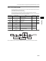
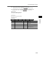
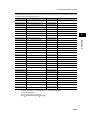
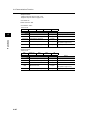
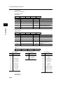
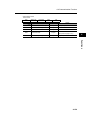
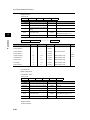
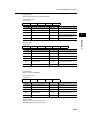
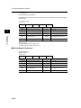
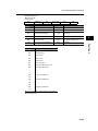
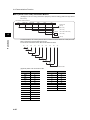
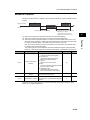
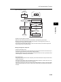
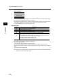
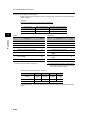
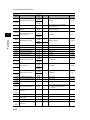
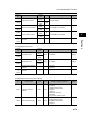
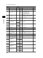
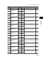
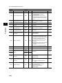
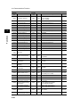
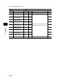
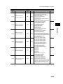
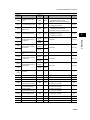
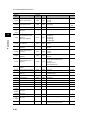
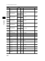
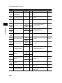
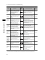
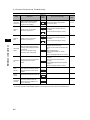
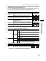
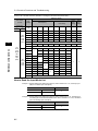
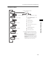
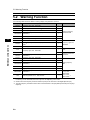
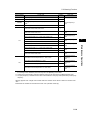
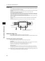
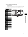
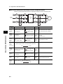
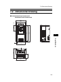
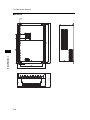
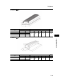
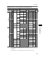
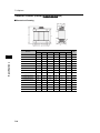
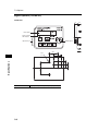
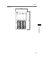
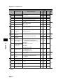
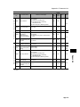
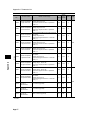
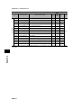
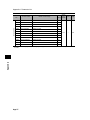
2-2 Wiring Arrangement of Main Circuit Terminals The terminal arrangement on the Inverter main circuit terminal block is shown below. Terminal arrangement 2 Design Ro Applicable model R/L1 S/L2 T/L3 U/T1 PD/+1 P/+ N/- RB V/T2 W/T3 G G To CHARGE LED indicator When not using the DC reactor, keep the PD/+1 - P/+ short-circuit bar attached. PD/+1 - P/+ short-circuit bar [EMC filter function switching method] In order to enable the EMC filter function, set up the plug inserted into the filter enable pin (J61) and filter disable pin (J62) as shown in the table below. Confirm that electrical power has been disconnected before performing this setup. Not doing so may result in electric shock. Also, use with the plug inserted. Dummy plug (green) Filter enable pin (J61) Short plug RX-A2004 to A2037 RX-A4004 to A4037 Ro,To: M4 Ground terminal: M4 Others: M4 Filter disable pin (J62) EMC filter disabled Filter enable pin (J61) Dummy plug (green) EMC filter enabled (factory default) Short plug Filter disable pin (J62) Short plug Dummy plug (green) Ro CHARGE LED indicator R/L1 S/L2 T/L3 PD/+1 P/+ G Ground terminal with short-circuit bar (shaded area) for EMC filter function switching To RB N/- U/T1 V/T2 PD/+1 - P/+ short-circuit bar G W/T3 RX-A2055, A2075 RX-A4055, A4075 Ro,To: M4 Ground terminal: M5 Others: M5 When not using the DC reactor, keep the PD/+1 - P/+ short-circuit bar attached. [EMC filter function switching method] RX-A2110 RX-A4110 Ro,To: M4 Ground terminal: M6 Others: M5 EMC filter enabled (factory default) 2-15 EMC filter disabled