1
·
'
tm
Dear Pascal MICROENGINE
Single Board Computer Customer:
Congratulations on your selection of the Pascal MICROENGINE
Single Board Computer. This product represents the latest
advance in microprocessor systems technology: hardware
designed for efficient high performance execution of Pascal
programs.
Enclosed with your board should be the following literature:
Installation Guide
Warranty Statement
Registration Form
Error Report Form
Additional information which may be of assistance to you is
contained in the WD/90 Pascal MICROENGINEReference Manual.
If you currently do not have a copy, the manual may be
purchased from Western Digital for $19.95. The Pascal
Operating System Diskette is also available in either
standard 8", single or double density, single or double sided
for $25.00. Purchase orders or telephone orders should be
directed to the Sales Department.
IN ORDER TO ENSURE THAT YOUR WARRANTY IS VALID, YOU MUST
COMPLETE THE REGISTRATION FORM IMMEDIATELY. The warranty is
described in the enclosed Warranty Statement, and lasts for
ninety (90) days after purchase. Once you have completed the
Registration Form, you will be put on The Microengine Company
Mailing List.
If you have ordered the Pascal Operating System Diskette and
with to continue to receive Pascal system software updates
past the warranty period, please check the box marked
MICROENGINE UPDATE SERVICE on the Registration Form. The
service includes new releases of the UCSD Pascal software.
The Microengine Company will bill you a basic charge of
$25.00 per release (after your warranty expires). To
maintain your subscription, the invoice must be paid within
ten (10) days after receipt.
A Subsidiary of
WESTERN DIGITAL
3128 Red Hill Avenue, Box 2180, Newport Beach California 92663
(714) 557-3550, TWX 910-595-1139
t
Page -2-
Should you experience problems after your warranty period,
you may return your Single Board Comput-er to The Microengi:ne
Company for repair. The current repair price for boards
which have not been subjected- to abno~mal conditions is §17S.
If your board is nonfunctioning and you wish to take
advantage of The 11icroengine Company's repair program, you
should call Microengine Technical Support. Send the
malfunctioning unit, freight prepaid, to:
The Microengine Company Repair Service
3128 Red Hill Avenue
Costa Mesa, California 92626
Your repaired Single Board Computer will be shipped to you
freight collect from Costa Mesa.
Thank you for your confidence in the Pascal MICROENGINE.
Sincerely,
The Microengine Company
f
Dear Pascal MICROENGINE User:
The following documentation is provided to help you configure your
Pascal MICROENGINE System.
1.
Procedure to properly configure the system.
2.
Wire lists for the centronics Series 700 line printers,
Shugart SA800/SA850 and Remex 4000-A floppy disk drives
and the system terminal.
3.
Charts of the recommended options to be installed in the
floppy disk drives and diagrams of where options are located.
4.
List of the responses to the SETUP program for the SOROC
IQ 120 and Beehive 150 terminals.
5.
Procedure for duplicating the operating system diskette.
80-013003-00Al
Installation Guide
A Subsidiary of
WESTERN DIGITAL
3128 Red Hill Avenue, Box 2180, Newport Beach California 92663
(714) 557-3550, TWX 910-595-1139
SYSTEM CONFIGURATION PROCEDURE
To configure a Pascal MICROENGINE
should be followed:
till
System the following procedure
I.
Cables for the floppy disk drive, system terminal and 1 ine
printer (if one is to be interfaced to the Microengi~e) must
be made. Wire I ists for these peripherals are given on page 1-2
of this document. Be sure to note the terminal wire 1 ist as
it is not a standard CRT cable.
2.
The floppy disk drives should have the recommended options
installed. Option charts for various drives can be found starting
on page 2-1 of this document.
3.
The Pascal MICROENGINE option switches must be set. Refer to the
I n the firs t ha 1f of
that manual containing the Pascal MICROENGINE Computer User's Manual,
the proper setting of the floppy disk and baud rate switches is
described in Section 2.
WD/90 Pasca I MI CROENG I NE Reference ~1anua 1 •
4.
Connect the floppy disk drive(s), system terminal and line printer
to the Microengine. Refer to Section 2.2 of the Pascal MICROENGINE
Computer User's Manual.
5.
Start the system. Section 3 of the Pascal MICROENGINE Computer User's
Manual describes starting the system. If a SOROC IQ 120/IQ 140
terminal (the operating system is configured for the SOROC) is being
used as the system terminal, the operating system should announce
itself in the top left-hand corner of the terndnal's screen and the
command prompt 1 ine should be displayed across the top of the screen.
If another terminal is being used, then the prompt 1 ines may be
misplaced. The software wil I have to be modified to meet the
specification of that terminal. The SETUP program, on the operating
system diskette, can be run to configure the software to the terminal
being used. In the second half of the WD/90 Pascal Reference Manual
containing the Pascal MICROENGINE Comp~ter Pascal Operations Manual,
the SETUP program is described in Section 4. Responses to the SETUP
program for various terminals are given starting on page 3-1 of this
document. Before running SETUP, make a duplicate copy of the operating
system diskette for back-up. The procedure for dupl icating the diskette
starts on pClge 1~-1 of this document.
6.
If, after running SETUP, the system terminal does not appear to be
properly, then it is possible that the cursor addressing
for the terminal being used is different than that of the SOROC.
In this case, a GOTOXY procedure must be created, compiled and bound
into the system software. Section 4.9" of the Pascal MICROENGINE
Computer Pascal Operations Manual describes the execution of the
BINDER program and gives an example of a GOTOXY procedure.
displ.lyill~1
7.
After the operating system software is configured for the terminal
you are using, make another copy of the reconf1gured operating system
for back-up.
( 1-1)
i
r
••
tm
Dear Pascal MICROENGINE
Single Board Computer Customer:
Congratulations on your selection of the Pascal MICROENGINE
Single Board Computer. This product represents the latest
advance in microprocessor systems technology: hardware
designed for efficient high performance execution of Pascal
programs.
Enclosed wi th your board should be the following literature:
Installation Guide
Warranty Statement
Registration Form
Error Report Form
Additional information which may be of assistance to you is
contained in the WD/90 Pascal MICROENGINEReference Manual.
If you currently do not have a copy, the manual may be
purchased from Western Digital for $19.95. The Pascal
Operating System Diskette is also available in either
standard 8", single or double density, single or double sided
for $25.00. Purchase orders or telephone orders should be
directed to the Sales Department.
IN ORDER TO ENSURE THAT YOUR WARRANTY IS VALID, YOU MUST
COMPLETE THE REGISTRATION FORM IMMEDIATELY. The warranty is
described in the enclosed Warranty Statement, and lasts for
ninety (90) days after purchase. Once you have completed the
Registration Form, you will be put on The Microengine Company
Mailing List.
If you have ordered the Pascal Operating System Diskette and
with to continue to receive Pascal system software updates
past the warranty period, please check the box marked
MICROENGINE UPDATE SERVICE on the Registration Form. The
service includes new releases of the UCSD Pascal software.
The Microengine Company will bill you a basic charge of
$25.00 per release (after your warranty expires). To
maintain your subscription, the invoice must be paid within
ten (10) days after receipt.
A Subsidiary of
WESTERN DIGITAL
3128 Red Hill Avenue, Box 2180, Newport Beach California 92663
(714) 557-3550, TWX 910-595-1139
Page -2-
t •
Should you experience problems after your warranty period,
you may return your Single Board Comput'er to The Microeng~ne
Company for repair. The current repair price for boards
which have not been subjected' to abno~mal conditions is ~175.
If your board is nonfunctioning and you wish to take
advantage of The 11icroengine Company's repair program, you
should call Microengine Technical Support. Send the
malfunctioning unit, freight prepaid, to:
The Microengine Company Repair Service
3128 Red Hill Avenue
Costa Mesa, California 92626
Your repaired Single Board Computer will be shipped to you
freight collect from Costa Mesa.
Thank you for your confidence in the Pascal MICROENGINE.
Sincerely,
The Microengine Company
Dear Pascal MICROENGlNE User:
The following documentation is provided to help you configure your
Pascal MICROENGINE System.
1.
Procedure to properly configure the system.
2.
Wire lists for the Centronics Series 700 line printers,
Shugart SA800/SA850 and Remex 4000-A floppy disk drives
and the system terminal.
3.
Charts of the recommended options to be installed in the
floppy disk drives and diagrams of where options are located.
4.
List of the responses to the SETUP program for the SOROC
IQ 120 and Beehive 150 terminals.
5.
Procedure for duplicating the operating system diskette.
80-013003-00Al
Installation Guide
A Subsidiary of
WESTERN DIGITAJ..
3128 Red Hill Avenue, Box 2180, Newport Beach California 92663
(714) 557-3550, TWX 910-595-1139
SYSTEM CONFIGURATION PROCEDURE
.
To configure a Pascal MICROENGINE tm System the following
procedure
should be followed:
1.
Cables for the floppy disk drive, system terminal and line
printer (if one is to be interfaced to the Microengi~e) must
be made. Wire 1 ists for these peripherals are given on page 1-2
of this document. Be sure to note the terminal wire list as
it is not a standard CRT cable.
2.
The floppy disk drives should have the recommended options
installed. Option charts for various drives can be found starting
on page 2-1 of this document.
3.
The Pascal MICROENGINE option switches must be set. Refer to the
WD/90 Pascal MICROENGINE Reference Manual. In the first half of
that manual containing the Pascal MICROENGINE Computer User1s Manual,
the proper setting of the floppy disk and baud rate switches is
described in Section 2.
4.
Connect the floppy disk drive(s), system terminal and line printer
to the Microengine. Refer to Section 2.2 of the Pascal MICROENGINE
Computer User1s Manual.
5.
Start the system. Section 3 of the Pascal MICROENGINE Computer User1s
Manual describes starting the system. If a SOROC IQ 120/IQ 140
terminal (the operating system is configured for the SOROC) is being
used as the system terminal, the operating system should announce
itself in the top left-hand corner of the term,inal's screen and the
command prompt 1 ine should be displayed across the top of the screen.
If another terminal is being used, then the prompt lines may be
misplaced. The software wil I have to be modified to meet the
specification of that terminal. The SETUP program, on the operating
system diskette, can be run to configure the software to the terminal
being used. In the second half of the WD/90 Pascal Reference Manual
containing the Pascal MICROENGINE Computer Pascal Operations Manual,
the SETUP program is described in Section 4. Responses to the SETUP
program for various terminals are given starting on page 3-1 of this
document. Before running SETUP, make a duplicate copy of the operating
system diskette for back-up. The procedure for dupl icating the diskette
starts on page 4-1 of this document.
6.
If, after running SETUP, the system terminal does not appear to be
displayinfl properly, then it is possible that the cursor addressing
for the terminal being used is different "than that of the SOROC.
In this case, a GOTOXY procedure must be treated, compiled and bound
into the system software. Section 4.9" of the Pascal MICROENGINE
Computer Pascal Operations Manual describes the execution of the
BINDER program and gives an example of a GOTOXY procedure.
7.
After the operating system software is configured for the terminal
you are using, make another copy of the reconf1gured o~erating system
for back-up.
( 1-1 )
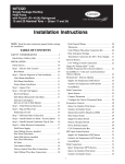
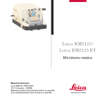
W1.~ LIST tOl TLOPPY b.i~ta
WIU LIST FOil crHfRDHICS Lnl~ PaIn.:;'..
DTive C.bh
aDU:l, 7~R.n:C, SHUCldT
C~NTllONICS
Cl:NTRONICS
. 1-
st~AL
HICROl.HCIHl
DALA STROll! -
30
2
1
14
Side Select
11
11
IU.D
19
.. 2
DATA 1 +
DATA 2 ...
DATA J +
DATA 4 +
26
DSntCTl
Z
DSll.!.CTl
21
1
30
DSnECTl
.3
l}
32
DSELECT4
22
1
3lo
Direction
2S
17
36
Step
6
38
WI)
8
40
Write Cate
27
20
INDEX
31
16
23
.. 6
DATA
~
+
16
24 .. 7
DATA 6 +
34
DATA 7 +
26
.. 9
DATA 8 +
22
Read,.
TU.O
12
15
46
Re.d Data
14
1
4ft
Write Protect
10
33
1
CND
1
}
CND
S
7
eND
27
.10 -
ACKN1..G -
n
28
.ll
BUSY'"
1
42
2S
.. 8
4
23
28
22
.. 5
29
1
21
.. I,
1'C 41
J-4
.36,
20
.. .3
'unctioll
24
9
eND
9
13
CHD
13
29
34
16
12
13
FAtn.r
2
PE +
SLCT ...
22
I
PABlY
I
I
STR.8POL -
tl./i~l
thCH'
Even wire. cut b.ck..
21
SACKB
llecon.u .. rlll~d t hn t
Odd· wire. tied toaether <t ie to conn. pin. 15 l. 17).
SignAl ground
6
LlST FOR S,¥STEH
Wl~
8
Termin.. 1
Pin Number
10
~
:=J
_ign.l. be roul.,d vi.
",;iir or ribbon cabl., uith altern"le Bround.
7
(J-2)
TERMINAL
.11
Pin Number
><=~
L,
7
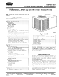
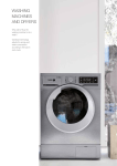
SHUGART SABOO OPTION CHART
TRACE
DESIGNATION
T3, T4, T5, T6
Tl
T2
DS1, DS2, DS3, DS4
RR
RI
R,I,S
HL
DS
vIP
NP
D
2, 4, 6 I 8 I 10, 12, 14, 16, 18
D1, D2, D4, DDS
A
B
X
C
Z
y
DC
*
**
DESCRIPTION
Terminations for Multiplexed Inputs
Terminator for Drive Select
Spare Terminator for Radial Head Load
Drive Select Input Pins
Radial Ready
Radial Index and Sector
Ready, Index, Sector Alternate Output Pads
Stepper Power from Hard Load
Stepper Power from Drive Select
Inhibit write when Write Protected
Allow Write when Write Protected
Alternate Input In
Nine Alternate I/O Pins
Customer Insta11ab1e Decode Drive Select
Radial Head Load
Radial Head Load
Radial Head Load
Alternate Input Head Load
In Use from Drive Select
In Use from HD LD
Alternate Output-Disk Change
Terminate the last drive on cable.
Jumper appropriate drive number.
(2-1)
RECOMMENDED
·CONFJ,:GUl\ATIC
OPEN
SHOE
X*
X
X
x**
X
X
X
X
X
X
X
X
X
X
X
X
X
X
X
X
X
2.
4.
6.
e.
10.
OC
14.
(1
I~ • • •
16 • • •
It~
•••
I • • ':
R ••
S ••
CSI £1
052 • •
OS311 •
054 • •
T31--'
T41-'
'--I
T~
!6'-:1
III
•
Jumper PhI!! I nstalled as Shipped
Test Point
SA800/801 PCB Component Locations
(2-2)
SHUGART SA850 OPTION CHART
TRACE
DESIGNATION
RECOMMENDED
DESCRIPTION
CONFIGURATIO~
OPEN
3H
RD9
DS1, DS2, DS3, DS4
lB, 2B, 3B, 4B
RR
RI
R
25
850
I
S
DC
HL
DS
WP
NP
D
Dl, D2, D4, DDS
DD
DL
A
B
X
C
Z
Y
Sl
S2
S3
TS, FS
*
**
Terminations for Multiplexed Standard Inputs
Pull Up for Multiplexed Optional Inputs
Drive Select Input Pins
Side Select option Using Drive Select
Radial Ready
Radial Index and Sector
Option Shunt for Ready Output
Two-Sided Status Output
Sector Option Enable
Index Output
Sector Output
Disk Change Option
Stepper Power from Head Load
Stepper Power from Drive Select
Inhibit Write when write Protected
Allow Write when write Protected
Alternate Input-In Use
Decode Drive Select Option
Standard Drive Select Enable
Door Lock Latch Option
Radial Head Load
Radial Head Load
Radial Head Load
Alternate Input-Head Load
In Use from Drive Select
In Use from Head Load
Side Select Option Using Direction Select
Standard Side Select Input
Side Select Option Using Drive Select
Data Separation option Select
TS
True Separation
FS = False Separation
Terminate the last drive on cable.
Jumper appropriate drive number;
(2-3)
SHom
X*
x
X
X
X
850
X
X
X
x
x
X
X
X
X
X
X
X
X
X
X
X
X
X
x·
X
FS
+
rnu
H
~n ®~
-i c,. + r-
+
FED
.~,
.n
c
e
A
::-;-.~m:" G"8 G ~8 G~i8·~"
L
I
G!
~_ -~ ~~
"~f:~
F.1
[j
L-.J
L-J
I
DS
••••
~~~
lG ~ lJ D:'U i
em]
0'
!!
lJ~ lJ
'
r:t
[j:~ ljeU! ·
[1"
n
,
."
(')
to
(')
o
s:
(3
z
N
I
..t='"
20
c
iU rn
R
R
L.....J
RR
Y
'---J
U
'-..-J
l----J
I : " 'B' 8 8 8· 8 8~ 8
en
:It
~
I
0
~~B
~ _,~.~~~,~ .~ .~ .B~~!~211
G00
(~,8~"'' ~ .~.~r:l~
r:l
~
00fu=
8'~"~·
lJ·.w it..
-{±§}@Q
+
.
~~
mo
~~ ~
~Q
CZ7
~...
I.. '. -GD- ~
~ s [l +
t;Jt:;J
-=~a~
1fEt~Y~
•
REMEX 4000-A OPTION CHART
TRACE
DESIGNATION
7A
DSl, DS2, DS3, DS4
IB, 2B, 3B, 4B
RR
RI
R
2S
4000
I
S
DC
HL
DS
tVP
NP
D
DL
A
B
X
C
Z
Y
Sl
S2
S3
TS, FS
-5V, -lSV
*
**
RECOMMENDED
CONF I GURAT 10:
SHOR
OPEN
DESCRIPTION
Terminations for Multiplexed Inputs
Drive Select Input Pins
Side Select Option Using Drive Select
Radial Ready
Radial Index and Sector
Option Shunt for Ready Output
Two-Sided Status Output
Sector Option Enable
Index Output
Sector Output
Disk Change Option
Stepper Power from Head Load
Stepper Power from Drive Select
Input Write when Write Protected
Allow Write when write Protected
Alternate Input-In Use
Door Lock Latch Option
Radial Head Load
Radial Head Load
Radial Head Load
Alternate Input-Head Load
In Use from Drive Select
In Use from Head Load
Side Select Option Using Direction Select
Standard Side Select Input
Side Select Option Using Drive Select
Data Separation Option Select
TS - True Separation
FS - False Separation
-5 Volt Supply Option
'1'e111linate the last drive on cable.
Jwnper appropriate drive number.
(2-5)
X*
x**
X
x
X
X
X
4000
X
X
X
x
x
X
X
X
x
X
X
X
x
X
X
X
X
X
FS
TS
x
u
28
TS
FS
18
28
38
48
83
-~
~'""--"=~---
81
Trac(: dnd Jumpl'r, Locations for 2S 1 DC, C, D, TS)
FS, DSl-DS/j , IB-4B, Sl-83.
(2-6)
-1
DL
:---..
i
N
RI
DS
Trace and Jumper Locations for DL, WP, NP, RI,
RR, S, A, I, X, B, A, HL, Z, DS, Y.
RESPONSE
(ASCII)
RESPONSE
(DECIMAL)
FIELD NAME
PREFIXED [KEY TO DELETE CHARACTEFQ
PREFIXED CkEY TO DELETE LINEa
PREFIXED [kEy TO END OF FI~
PREFIXED [MOVE CURSOR HOME]
PREFIXED [MOVE CURSOR RIGH'lj
PREFIXED (MOVE CURSOR Up]
PREFIXED [NON-PRINTING CHARACTE~
SCREEN HEIGHT
SCREEN WIDTH
VERTICAL MOVE DELAY
FALSE
FALSE
FALSE
FALSE
FALSE
FALSE
FALSE
24
80
15
(3-2)
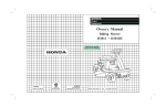
LIST OF RESPONSES TO THE SETUP PROGRAM .
BEEHIVE 150
FIELD NAME
BACKSPACE
DISK READ RATE
DISK SEEK RATE
DISK WRITE RATE
EDITOR "ACCEPT" KEY
EDITOR II ESCAPE" KEY
ERASE LINE
ERASE SCREEN
ERASE TO END OF LINE
ERASE TO END OF SCREEN
111\8 85101\
BAS CLOCK
HAS LOWER CASE
HAS RANDOM CURSOR ADDRESSING
HAS SLOW TERMINAL
KEY FOR BREAK
KEY FOR FLUSH
KEY FOR STOP
KEY TO DELETE CHARACTER
KEY TO DELETE LINE
KEY TO END FILE
KEY TO MOVE CURSOR DOWN
KEY TO MOVE CURSOR LEFT
KEY TO MOVE CURSOR RIGHT
KEY TO MOVE CURSOR UP
LEAD-IN CHAR FROM KEYBOARD
LEAD-IN TO SCREEN
MOVE CURSOR HOME
HOVE CURSOR RIGHT
HOVE CURSOR UP
NON-PRINTING CHARACTER
PREFIXED [pELETE CHARAC'l'E~
PREFIXED [EDITOR" ACCEPT" KEXJ
PHEFIXED [EDITOR "ESCAPE" KE~
PREFIXED [PRASE LINEl
PREFIXED [ERASE scRiEJ{J
PREFIXED (1:RASE TO END Ot' LINE]
PREFIXED [ERASE TO END OF SCREEW
PREFIXED [KEY FOR BREA@
PREFIXED U<EY FOR FLUSm
PREFIXED [KEY FOR MOVING CURSOR Dm·nf]
PREFIXED [KEY FOR MOVING CURSOR LEF'i.:}
PREJ?IXED U<EY FOR MOVING CURSOR RIGHrfj
PREPIXED [lillY FOR HOVING CURSOR U~
PREFIXED [j<Ey FOR STO:fj
ASCII
DECIMAL
8
BS
Dependent on Disk Speed - see manual (update)
Dependent on Disk Speed ~ see manu~l (update)
Dependent on Disk Speed - see manual (update)
ETX
3
27
75
69
75
74
ESC
K
E
K
J
FALSE
FALSE
TRUE
TRUE
FALSE
0
NUL
ACK
PC3
BS
PEL
ETX
LF
BS
FF
VT
NUL
ESC
H
FF
FT
?
6
19
8
127
3
10
8
12
11
0
27
72
12
11
63
FALSE
FALSE
FALSE
TRUE
TRUE
TRUE
TRUE
FALSE
FALSE
FALSE
FALSE
FALSE
FALSE
FALSE
( 3-3)
FIELD NAME
PREFIXED [i<Ey TO DELETE CHARACTER]
PREFIXED ~EY TO DELETE LIN§
PREFIXED ~Y TO END OF FI~
PREFIXED (MOVE CURSOR HOM~
PREFIXED [NOVE CURSOR RIGH~
PREFIXED [MOVE CURSOR U~
PREFIXED [NON-PRINTING CHARACTE~
SCREEN HEIGHT
SCREEN WIDTH
VERTICAL MOVE DELAY
ASCII
DECIMAL
FALSE
FALSE
FALSE
TRUE
FALSE
FALSE
FALSE
24
80
15
(3-4)
DUPLICATING THE OPERATING SYSTEM DISKETTE
Procedure:
1.
After powering the Microengine System, take the Pascal Operating
System Diskette delivered with the the Microengine a~d place it
in the floppy disk drive optioned as DSl (Volume #4:).
Press the Reset button. This should load the UCSD Pascal Operatirig
System from the diskette into the Microengine memory and execute it.
The following should be displayed on the terminal screen:
Welcome OSXX to
UCSD Pascal System 3.0
Current Date is dd-mm-yy
2.
Assuming you have the above prompt you are now ready to make a
back-up copy of the Operating System Diskette. The command prompt
line should be at the top of the terminal screen:
Command:
3.
E(dit, R(un, F(ile, C(omp, L(ink, X(exute, A(ssem, D{ebug, 1
Type an "F" on the terminal keyboard. This invokes the Filer which
contains commands used primarily for maintaining files on the floppy
diskette. The following prompt line will appear on the top of the
te rm i na 1 screen:
Filer:
G(et, S(ave, W(hat, N(ew, L(dir, R(em, C(hange, T(ran, D(ate, Q(ui
4.
Place a preformatted blank diskette into the drive optioned as DS2
(Volume #5:).
5.
Type a liT" to transfer from the Operating System diskette to the new
diskette. The following prompt will app~ar:
Transfer what file?
6.
Type a 11114:" to specify that a complete volume transfer is going to
take place. The next prompt will be:
To where?
7.
Type a "115:" to specify that the volume is to be transferred to the new
diskette. A message indicating that the transfer is completed will
then be given. If this does not occur, proceed to the next step anyway
to check for bad blocks.
8.
Type a "?" to get the rest of the Filer commands.
be displayed:
The following will
Filer B(ad-blks, E(xt-dir, K(runch, M(ake, P(refix, V(ols,
X(amine, Z(ero
(4-1)
9.
Type a "B" to run a bad blocks scan on the new d i sk"ette.
following prompt will be displayed:
The
Bad blocks scan of what volume?
10.
Type in 11#5:". The blocks being tested will be displayed on the
screen. Should the scan detect a bad block, it will list it as
being bad. If this occurs, try another new diskette and continue
from Step 4. If the scan is successful, the system will announce
o bad blocks.
11.
Type a "Q" to Q(uit the Filer.
at the top of the screen.
12.
Type a "X" for eX(ecute.
The command prompt should reappear
The following prompt will be displayed:
Execute what file?
13.
Type "BOOTER" to execute the BOOTER util ity. This util lty places
a BOOTSTRAP on the diskette. The following prompt will appear:
Unit to write boot to 4,5,9,10 :
14.
Type a "5/1.
This prompt wll then be displayed:
Unit boot is on
4,5,9,10 :
15.
Type "4/1 to indicate the del ivered system diskette. A message
indicating that the bootstrap was transferred will then be displayed.
16.
Remove the diskette in Unit 5 and keep it as a back~up should anything
happen to the delivered operating system diskette. Do not keep the
two diskettes in the system at the same time. They both have the same
volume name as a result of the transfer and this can lead to problems
if subsequent commands are given.
(4-2)
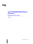
WESTERN DIGITAL CORPORATION
Q A FINAL ACCEPTANCE FORM
O,[)EL # 9(1(1068 ( CF~G
E~R I AL #
142E:
8TE
4/21./80
E:STED 8'T' t'1P
i~:'
391.7)
I NTER PORT
PORT
PORT
D,LD BOOT
')T
[
[
BOOT
]
I5K COP'T'
rs~(
VERIF'T'
]
[
(~:~f0
-(~:'{
]
.
!SlIAL INSPECT
I
i:'PROVED FOR SH I PPt'1ENT
[
'\
',.
\
'
\
]
CERTIFICATE OF WARRANTY
The MICROENGINETM Company (TMC) warrants its hardware against defects in materials and
workmanship for a period of ninety (90) days from the date of shipment to Customer. During the
warranty period, TMC will, at its option, repair or replace hardware which proves to be defective.
TMC warrants that its software will execute its programming instructions when properly installed on the
appropriate TMC hardware. TMC does not warrant that operation of TMC software will be uninterrupted
or error free. During the warranty period, TMC will provide its normal Software Support Services. at no
Charge.
The foregoing warranty shall not apply to defects resulting from:
1. improper or inadequate maintenance;
2. non-TMC-suppJied software or interfacing;
3. unauthorized modification or misuse;
4. operation outside of the environmental specifications for the product; or
5. improper site preparation.
This warranty is in lieu of all other warranties expressed or implied, including any warranty of
merchantability or fitness for a particular purpose, and TMC neither assumes, nor authorizes any
person or firm to assume for it, any other or further obligation or liability in connection with the sales,
installation or use of any product. Under no circumstances shall TMC or any affiliate or TMC have any
liability whatsoever for loss of use or for any indirect, incidental or consequential damages.
Please fill out and return Registration Form to TMC.
1~~'''
•.• ,
~
'.
.,
~..\t lUtt1dr!~
A Subsidiary of WESTERN DIGITAL
3128 Redhill Avenue, Box 2180
Newport Beach, CA. 92663
(714) 557-3550, TWX 910-595-1139
A Subaldhsry of WESTERN DIGITAL
Problem
Report
Product Name
Product No. _ _ _ _ _ _ _ _ _ _ _ _ _ _ _ _ _ Revision
Product Type
o
o
o
Hardware
Software
Docu mentation
Description of Problem
,
Reported By
N arne ______"____________,__,___
Company
Address
Phone No.