1
PREFACE
Thank you for purchasing the LogiTouch integrated development software,
"LogiTouch Editor Ver. 1.0”, hereafter referred to as the “LT Editor".
Please read this manual carefully in order to use this software properly, and
be sure to keep this manual handy for future reference.
NOTES
(1) The copyrights to all programs and manuals included in the LT Editor
Ver. 1.0 Operation Manual - Screen Creation Guide (hereinafter
referred to as "this product") are reserved by the Digital Electronics
Corporation. Digital grants the use of this product to its users as
described in the "Software Operating Conditions" documentation,
included with this product's CD-ROM. Any actions violating the
above-mentioned conditions are prohibited by both Japanese and
foreign regulations.
(2) The contents of this manual have been thoroughly inspected. However, if you should find any errors or omissions in this manual, please
inform your local LT Editor representative of your findings.
(3) Regardless of article (2), the Digital Electronics Corporation shall not
be held responsible for any damages or third party claims resulting
from the use of this product.
(4) Differences may occur between the descriptions found in this manual
and the actual functioning of this product. Therefore, the latest information on this product is provided in data files (i.e. Readme.txt files,
etc. ) and in separate documents. Please consult these sources as well
as this manual prior to using the product.
(5) Even though the information contained in and displayed by this product may be related to intangible or intellectual properties of the Digital
Electronics Corporation or third parties, the Digital Electronics Corporation shall not warrant or grant the use of said properties to any users
and/or other third parties.
(6) The specifications set out in this manual are for overseas products
only. As a result, some differences may exist between the specifications given here and for those of the identical Japanese product.
© Copyright 2001 Digital Electronics Corporation. All rights reserved.
Digital Electronics Corporation, May 2001
For the rights to trademarks and trade names, see “TRADEMARK RIGHTS”.
LogiTouch Editor Ver. 1.0 Operation Manual - Screen Creation Guide
1
Preface
TRADEMARK RIGHTS
All company or product names used in this manual are the trade names,
trademarks (including registered trademarks), or service marks of their
respective companies.
This product omits individual descriptions of each of these rights.
Trademark / Trade Name
Right Holder
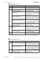
Microsoft, MS, MS-DOS, Windows,
Windows 95, Windows 98, Windows Me,
Microsoft Corporation, USA
Windows NT, Windows 2000 Windows
Explorer, Microsoft Excel 95
Intel, Pentium
Intel Corporation, USA
Digital Electronics Corporation
Pro-face, Flex Network
(in Japan and other countries)
Ethernet
Western Digital Electric Corporation, USA
International Business Machines
IBM, VGA, PC/AT
Corporation (IBM), USA
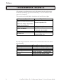
The following terms differ from the above mentioned formal trade names
and trademarks.
Term used in this manual
Windows 95
Windows 98
Windows Me
Windows NT
Windows 2000
MS-DOS
2
Formal Trade Name or Trademark
Microsoft® Windows®95 Operating System
Microsoft® Windows®98 Operating System
Microsoft® Windows®Me Operating System
Microsoft® Windows NT ® Operating System
Microsoft® Windows®2000 Operating System
Microsoft® MS-DOS® Operating System
LogiTouch Editor Ver. 1.0 Operation Manual - Screen Creation Guide
Preface
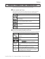
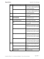
MANUAL SYMBOLS AND TERMINOLOGY
This manual uses the following symbols and terminology.
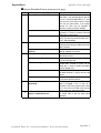
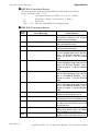
Safety Symbols and Terms
This manual uses the following symbols and terms to identify important
information related to the correct and safe operation of this product.
Symbol
Description
Indicates a potentially hazardous situation that could result in serious injury
or death.
Indicates a potentially hazardous situation that could result in minor injury or
equipment damage.
Indicates a potentially damaging action or dangerous situation that could
result in abnormal equipment operation or data loss.
Indicates instructions or procedures that must be performed to ensure
correct product use.
Indicates instructions or procedures that must not be performed.
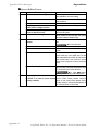
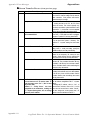
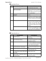
General Information Symbols and Terms
This manual uses the following symbols and terms for general information.
Symbol
Description
Provides hints on correct product use, or supplementary
information.
Indicates an item's related information (manual name, page
number).
Esc
Ctrl
External
Device
LT
LT Editor
Refers to keys on the computer keyboard.
Keyboard Compatibility List
Indicates an external device (temperature controller, inverter,
etc.). Does not include devices connected via the Flex Network
or DIO.
Generic name for the "LogiTouch Series" Graphic Logic
Controller made by Digital Electronics Corporation.
Indicates LogiT ouch Editor Version 1.0 (hereinafter referred as
"this product"), LogiTouch integrated development software
made by Digital Electronics Corporation.
LogiTouch Editor Ver. 1.0 Operation Manual - Screen Creation Guide
3
Preface
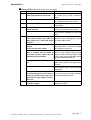
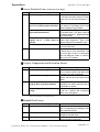
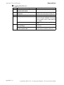
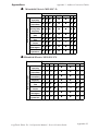
Keyboard Compatibility List
This manual uses the following symbols to indicate computer keyboard
keys.
The key names used by your computer keyboard may differ. Please use the
chart below for reference.
Type
Symbol
PS/2 Compatible
101 Keyboard
Esc
Esc
Tab
Tab
Ctrl
Ctrl
Shift
↑ Shift
Alt
Alt
Delete
Delete
Back
space
Backspace
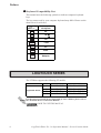
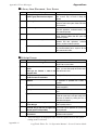
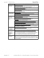
LOGITOUCH SERIES
The LT Editor supports the following LT models.
Series
Type
Type-A1
Type-A1
LogiTouch Series
Type-B
Type-C
Product
Model
GLC150B-XY32SK
GLC150B-XY32SC
GLC150B-RSFL
GLC150B-XY32SK
GLC150-BG41-XY32SK-24V
GLC150-BG41-XY32SC-24V
GLC150-BG41-FLEX-24V
GLC150-BG41-RSFL-24V
For the types of external devices supported by the LT Editor, please refer to
the "External Device Connection Manual".
HOW TO USE THIS MANUAL
4
LogiTouch Editor Ver. 1.0 Operation Manual - Screen Creation Guide
Preface
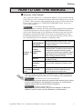
HOW TO USE THIS MANUAL
Structure of the Manual
The "LogiTouch Editor Ver. 1.0 Operation Manual - Screen Creation Guide"
is the first in a series of manuals for this product and explains how to use the
LT Editor. There are three other manuals in the series as well as online help.
Please refer to "Chapter 1 LT EDITOR FUNDAMENTALS" for an overview of this product.
1.6 LT Editor Manuals and Help
In addition to these manuals, data files containing supplemental information
on updated functions are also provided.To read these additional data files,
click on the [Start] button in your Windows OS main screen and select the
[Programs]→[LogiTouch] menu. Then, click on the [Readme] selection.
For detailed information on LT series of operator interfaces, please refer to
the "LogiTouch Series User Manual". (Separately sold)
LT Editor
Describes the operating procedures for the LT Editor and
Operation Manual all functions except for Logic Program development
(provided as a PDF file).
(this manual)
LT Editor
Programming
Included on
Manual
CD-Rom
Parts List
External Device
Connection
Manual
Available on
the LT Editor Online Help
screen
Describes logic program development. The manual
consists of two parts, "Programming" which focuses on
the tutorial lesson to help users to learn the operation
procedures, and "Functions" which explains the software
settings required for the combination of the LT main unit
and the LT Editor (provided as a PDF file).
Describes the LT Editor's pre-made Parts and symbols
(provided as PDF data).
Describes the methods for connecting the LT to external
devices of various manufacturers (provided as a PDF
file).
Describes the methods for setting the LT Editor's windows
and dialog boxes, instructions and functions of logic
programs as well as how to set each driver.
• Address settings described in these manuals are for explanatory purposes
only. Appropriate addresses must be set according to your requirements.
External Devices Connection Manual
• If you have any questions about the contents of this manual, please contact
your local LT distributor. LT distributors will answer to your technical
inquiries and provide you with technical consultation.
Software Trouble Report
If you have any question about your personal computer or Microsoft®
Windows®, please contact your PC distributor or manufacturer.
LogiTouch Editor Ver. 1.0 Operation Manual - Screen Creation Guide
5
Preface
Chapter Breakdown
This manual contains 10 chapters and an appendix.
The following is a general description of each chapter:
CHAPTER 1: FUNDAMENTALS OF LOGITOUCH EDITOR
This chapter describes the operation of the LT Editor from start to finish. It
also explains the overall structure of the LT Editor Project Manager, Logic
Program Editor, and Screen Editor areas.
CHAPTER 2: CREATING BASE SCREENS
This chapter describes the basic operations and terminology used for drawing functions, such as “Part”, “Library”, and “D-Script”.
CHAPTER 3: DRAWING APPLICATIONS: CREATING AND USING
SCREENS
This chapter describes the procedures for creating and using various screens,
such as the M (Mark) Screen and I (Image Library) screens, which enable
you to create high-quality images and provide advanced-level functionality.
CHAPTER 4: SCREEN AND PROJECT MANAGEMENT
This chapter describes the procedures for editing and saving created screens
and project files, and information management procedure.
CHAPTER 5: CREATING AND EDITING ALARMS
This chapter describes the alarm creating and editing procedures.
CHAPTER 6: LT INITIAL AND SYSTEM SETTINGS
This chapter describes the initial setup procedure required to use the LT
display unit. For details, please refer to the online help or the users’ manual
for the LT main unit.
CHAPTER 7: TRANSFERRING DATA
This chapter describes the procedures for sending screens and logic programs created with the LT Editor to an LT display unit.
CHAPTER 8: SIMULATION
This chapter describes the procedures for simulating the operation between
an LT and LT Editor.
CHAPTER 9: PRINTING
This chapter describes the procedure for printing created screens.
CHAPTER 10: ADVANCED FEATURES
This chapter describes the procedures for using the LT Editor's advanced
functions such as filing data (recipe) and logging functions.
6
LogiTouch Editor Ver. 1.0 Operation Manual - Screen Creation Guide
Preface
APPENDIX
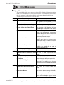
• Error Messages
Lists the error messages, causes of the errors and solutions that will be
displayed during operation of LT Editor.
• Troubleshooting
Provides information for diagnosis and corrective actions for dealing with
errors or abnormal operation.
• Address Conversion Tables
Lists the addresses for each manufacturer’s product.
• Software Trouble Report
This is a form in which you can write down any trouble you might have with
the LT Editor and your LT Editor’s operating conditions that can then be
sent to us by facsimile. If you have any inquires about the LT Editor, please
use this form.
LogiTouch Editor Ver. 1.0 Operation Manual - Screen Creation Guide
7
Preface
PRECAUTIONS
CD-ROM Usage Precautions
To prevent CD-ROM damage or malfunctions, please observe the following
instructions:
STOP
• Do not remove the CD-ROM from the CD-ROM drive while the drive’s
operation lamp is lit.
• Do not touch the CD-ROM recording surface.
• Do not place CD-ROMs in a place where they may be exposed to extremely
high or low temperatures, high humidity, or dust.
Product Usage Precautions
To prevent program malfunction or accidents, be sure to observe the following instructions:
!
Warning
STOP
Touch panel switches should NOT be used for a
device’s Emergency Stop Switch. Generally speaking, all industrial machinery/systems must be
equipped with a mechanical, manually operated
emergency stop switch. Also, for other kinds of
systems, similar mechanical switches must be
provided to ensure safe operation of those systems.
• Do not turn off your personal computer’s power switch during the execution of a program.
• Do not change the contents of this product’s project files using the Text
Editor software.
8
LogiTouch Editor Ver. 1.0 Operation Manual - Screen Creation Guide
Preface
Drawing
• The LT Editor’s display screen and descriptions used in the manuals are
based on the color display when the LT main unit is in the "REVERSE"
LCD mode. Please note that white/black color on the LT Editor screen and
LT main unit screen will be reversed when the LCD is in the "NORMAL"
mode.
"LogiTouch Series User Manual"
• When an LT unit is vertically installed, the panel’s coordinates will differ from those
used on the screen editor software. Therefore, when you enter screen coordinates
using tags or D-Script, please consider the LT’s orientation.
(0. 0) on the screen editor software
(0. 0) on the LT series’ panel
Functions and Settings
• Certain functions and settings supported by the LT unit are not supported
by the LT Editor program, and vice versa.
[Setting and functions set via the LT unit (Not by LT Editor) ]
- Language Font selection
- LT Date/Time settings
- LT Self-Diagnosis Function
[Functions and settings supported by LT Editor only (Not by the LT
unit)]
The following settings are included in the “LT System Settings” area:
- "Checksum Verification" settings
- Screen Change Order in hierarchical display mode
- Screen Change according to standby mode time
- Shift to OFFLINE mode settings
- Setting the frequency of Keypad Display processing performed per
scanning time
- LT unit's internal memory (LS area) backup function settings
- "Error Display Reset" settings
- "Watch Dog" settings
- Communication Monitoring Period settings (Designate transmission wait time)
LogiTouch Editor Ver. 1.0 Operation Manual - Screen Creation Guide
9
Preface
Logic Program Restrictions
• LT variables are handled using 32-bit device Low/High order.
• Display function by parts cannot handle real numbers.
• Values different from the input values may display during monitoring due
to the difference in the real number accuracy between a personal computer and the LT.
• If the LT's logic time (scan time) becomes too long, the sampling time
designated for the trend graph may not be accurately maintained.
• When using the Memory Link Method, the change in the value of variables cannot be entirely displayed by a trend graph.
• All LT Retentive Variable data is retained by SRAM backup memory that
uses a lithium battery. The battery's back up period lasts approximately
60 days in its initial condition (fully charged), and approximately 6 days
when the battery life is almost finished. If you need to back up data for a
longer period, you need to either use back up data in your host computer,
or configure the Editor system so that the Editor can back up data.
10
LogiTouch Editor Ver. 1.0 Operation Manual - Screen Creation Guide
Preface
TABLE OF CONTENTS
PREFACE ........................................................................................................................ 1
Trademark Rights ..................................................................................................................... 2
Manual Symbols and Terminology .......................................................................................... 3
LogiTouch Series ..................................................................................................................... 4
How to Use This Manual ......................................................................................................... 5
PRECAUTIONS ...................................................................................................................... 8
TABLE OF CONTENTS ....................................................................................................... 11
CHAPTER1: LT EDITOR FUNDAMENTALS
1.1
Overview.............................................................................................................. 1-2
1.1.2 Prior to Operating the LT .......................................................................................... 1-3
1.2
From Start to Finish ......................................................................................... 1-4
1.2.1 Getting Started ........................................................................................................... 1-4
1.2.2 Creating/Selecting/Saving a Project .......................................................................... 1-5
1.2.3 Creating/Editing/Saving a Logic Program .............................................................. 1-10
1.2.4 Opening/Closing/Saving a Screen ........................................................................... 1-12
1.2.5 Quitting LT Editor ................................................................................................... 1-17
1.3
Project Manager ............................................................................................. 1-18
1.3.1 Project Manager Areas and Functions .................................................................... 1-18
1.4
Logic Program Editor ................................................................................... 1-20
1.4.1 Logic Program Editor Item Names and Functions .................................................. 1-20
1.5
Screen Editor................................................................................................... 1-22
1.5.1 Screen Editor Item Names and Functions ............................................................... 1-23
1.5.3 Tool/Icon Display .................................................................................................... 1-25
1.5.2 Display Area (50%, 100%, 200%) .......................................................................... 1-25
1.6
LT Editor Manuals and Help ...................................................................... 1-26
1.6.1 Browsing Help Topics ............................................................................................. 1-27
1.6.2 Browsing the Home Page ........................................................................................ 1-29
CHAPTER2: CREATING BASE SCREENS
2.1
Parts ..................................................................................................................... 2-2
2.1.1 Bit Switches ............................................................................................................. 2-17
2.1.2 Word Switches ......................................................................................................... 2-21
2.1.3 Function Switches ................................................................................................... 2-24
LogiTouch Editor Ver. 1.0 Operation Manual - Screen Creation Guide
11
Preface
2.1
Parts .....................................................................................................................2-2
2.1.1 Bit Switches ............................................................................................................. 2-14
2.1.2 Word Switches ......................................................................................................... 2-17
2.1.3 Function Switches ................................................................................................... 2-20
2.1.4 Lamps ...................................................................................................................... 2-23
2.1.5 Bar Graphs ............................................................................................................... 2-26
2.1.8 Pie Graphs................................................................................................................ 2-31
2.1.7 Half Pie Graphs ....................................................................................................... 2-36
2.1.8 Meters ...................................................................................................................... 2-41
2.1.9 Trend Graphs ........................................................................................................... 2-46
2.1.10 Keypad Display ....................................................................................................... 2-51
2.1.11 Alarm Display.......................................................................................................... 2-57
2.1.12 File Name Display ................................................................................................... 2-61
2.1.13 Data Logging Display .............................................................................................. 2-67
2.1.14 Numeric Displays .................................................................................................... 2-73
2.1.15 Message Display ...................................................................................................... 2-77
2.1.16 Date Displays ........................................................................................................... 2-83
2.1.17 Time Displays .......................................................................................................... 2-86
2.1.22 Picture Displays ....................................................................................................... 2-88
2.2
Drawing ............................................................................................................ 2-94
2.2.1 Dot
....................................................................................................................... 2-95
2.2.2 Line/Poly-line .......................................................................................................... 2-96
2.2.3 Square/Rectangle ..................................................................................................... 2-98
2.2.4 Circle/Oval............................................................................................................. 2-100
2.2.5 Arc/Pie ................................................................................................................... 2-102
2.2.6 Fill
..................................................................................................................... 2-104
2.2.7 Filled Polygon........................................................................................................ 2-106
2.2.8 Scale ..................................................................................................................... 2-108
2.2.9 Tex
..................................................................................................................... 2-111
2.2.10 Load Screens.......................................................................................................... 2-115
2.2.11 Load Mark ............................................................................................................. 2-118
2.3
Object Editing ............................................................................................... 2-119
2.3.1 Selecting Objects ................................................................................................... 2-120
2.3.2 Moving Objects ..................................................................................................... 2-126
2.3.3 Scaling Up/Down .................................................................................................. 2-127
2.4.4 Cut
..................................................................................................................... 2-128
2.3.5 Copy ..................................................................................................................... 2-129
2.3.6 Paste ..................................................................................................................... 2-130
12
LogiTouch Editor Ver. 1.0 Operation Manual - Screen Creation Guide
Preface
2.3.7 Pasting Instruction Data ........................................................................................ 2-131
2.3.8 Duplicate ................................................................................................................ 2-137
2.3.9 Delete ..................................................................................................................... 2-140
2.3.10 Align ..................................................................................................................... 2-141
2.3.11 Rotate Left/ Rotate Right ...................................................................................... 2-142
2.3.12 Mirror X/ Mirror Y ................................................................................................ 2-143
2.3.13 Group/ Ungroup ..................................................................................................... 2-144
2.3.14 Bring to Front/ Send to Back ................................................................................. 2-146
2.3.15 Changing Attributes............................................................................................... 2-147
2.3.16 Changing Coordinates ........................................................................................... 2-149
2.3.17 Editing the Node of a Multi-segment Line............................................................ 2-150
2.4.18 Convert (Import) Bit map ...................................................................................... 2-151
2.3.19 Transferring a Screen to the Clipboard ................................................................. 2-153
2.3.20 Converting a Screen to a Bitmap File ................................................................... 2-154
2.3.21 Redraw Screen ....................................................................................................... 2-156
2.3.22 Undo ..................................................................................................................... 2-157
2.3.23 Redo ..................................................................................................................... 2-157
2.4
Library Items ................................................................................................ 2-158
2.4.1 Registering Library Items ...................................................................................... 2-162
2.4.2 Placing Library Items ............................................................................................ 2-166
2.4.3 Editing Library Items............................................................................................. 2-168
2.4.4 Saving Libraries and Quitting ............................................................................... 2-173
2.5
D-Script/Global D-Script ........................................................................... 2-175
2.5.1 D-Script Settings ................................................................................................... 2-176
2.5.2 D-Script Commands .............................................................................................. 2-183
2.5.3 D-Script / Global D-Script Limitations ................................................................. 2-198
2.5.4 Notes on Operation Results ................................................................................... 2-200
2.5.5 Logical Operation Examples ................................................................................. 2-201
2.5.6 Bit Operation Examples ........................................................................................ 2-202
2.5.7 Conditional Branches ............................................................................................ 2-203
2.5.8 Application Example (1) ....................................................................................... 2-204
2.6
Data Sampling ............................................................................................... 2-207
2.9.1 Grid/Snap ............................................................................................................... 2-207
2.6.1 Data Sampling Settings ......................................................................................... 2-207
2.7
Efficient Drawing Techniques................................................................... 2-213
2.9.1 Grid/Snap ............................................................................................................... 2-213
2.7.1 Grid/Snap ............................................................................................................... 2-213
2.7.2 Screen Property Settings ....................................................................................... 2-215
LogiTouch Editor Ver. 1.0 Operation Manual - Screen Creation Guide
13
Preface
2.7.3 Preview Screen ...................................................................................................... 2-219
2.7.4 Screen Data List .................................................................................................... 2-219
2.7.5 Part Reference List ................................................................................................ 2-221
2.7.6 Data Sampling List ................................................................................................ 2-223
2.7.7 Cross Reference List ............................................................................................. 2-225
2.7.8 Load Screen List .................................................................................................... 2-228
2.7.9 Display of Screen Level Change Structure ........................................................... 2-229
2.8
DXF Conversion ........................................................................................... 2-230
2.8.1 Conversion from DXF File to Base Screen (DXF® Screen) ................................. 2-230
2.8.2 Conversion from Base Screen to DXF File (Screen DXF®) ................................ 2-236
CHAPTER 3: DRAWING APPLICATIONS
- CREATING and USING SCREENS
3.1
Creating a Mark: the Mark Screen ..............................................................3-2
3.2
Creating an Image: the Image Screen ....................................................... 3-23
CHAPTER 4: SCREEN AND PROJECT MANAGEMENT
4.1
Screen Editing ....................................................................................................4-2
4.1.1 Listing/Copying/Deleting Screen .............................................................................. 4-2
4.1.2 Copying Screens from Other Projects ....................................................................... 4-7
4.2
Project Editing ................................................................................................. 4-11
4.2.1 Deleting Project Files .............................................................................................. 4-11
4.2.2 Rebuilding A Project (Rebuild)............................................................................... 4-12
4.2.3 Converting Addresses and Device Codes ............................................................... 4-15
4.2.4 Convert Load Screens.............................................................................................. 4-17
4.2.5 Symbol Editor .......................................................................................................... 4-19
4.2.6 Changing a Project’s LT Type ................................................................................. 4-27
4.2.7 Changing Your Project’s External Device ............................................................... 4-28
4.3
Project Compression/Decompression ........................................................ 4-29
4.3.1 Compressing a Project File ..................................................................................... 4-30
4.3.2 Decompressing a Project File .................................................................................. 4-33
4.4
Information Display ...................................................................................... 4-35
4.4.1 Project Information .................................................................................................. 4-35
4.4.2 Screen Information .................................................................................................. 4-37
4.4.3 Version Information ................................................................................................. 4-37
14
LogiTouch Editor Ver. 1.0 Operation Manual - Screen Creation Guide
Preface
CHAPTER 5 CREATING AND EDITING ALARMS
5.1
Alarm Creation and Editing ....................................................................... 5-2
5.1.1 Alarm Editor .............................................................................................................. 5-2
5.1.2 Creating an Alarm ..................................................................................................... 5-4
5.1.3 Editing Alarm Data .................................................................................................... 5-5
5.1.4 Alarm Import/Export ............................................................................................... 5-12
CHAPTER 6: LT INITIAL AND SYSTEM SETTINGS
6.1
Menu Setting Items: LT Setup ....................................................................... 6-2
CHAPTER 7:
7.1
TRANSFERRING SCREENS
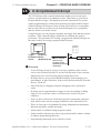
Prior to Transferring Data .............................................................................7-2
7.1.1 LT Screen Transfer Cable .......................................................................................... 7-2
7.2
Transferring Data and Logic Programs ......................................................7-3
7.2.1 Transfer Settings ........................................................................................................ 7-4
7.2.2 Passwords .................................................................................................................. 7-7
7.2.3 Transfer Preparation .................................................................................................. 7-9
7.2.4 When Sending Screens and Logic Programs Together To the LT .......................... 7-10
7.2.5 When Sending Logic Programs ............................................................................... 7-12
7.2.6 When Receiving Data From the LT......................................................................... 7-13
7.2.7 Sending Programs with the Logic Program Editor ................................................. 7-14
7.3
Options .............................................................................................................. 7-16
7.3.1 LT Internal Screen Data Information ...................................................................... 7-16
CHAPTER 8: SIMULATION
8.1
Overview..............................................................................................................8-2
8.1.1 General Description of the Simulation Screen .......................................................... 8-3
8.1.2 Transferring Simulation Protocol .............................................................................. 8-8
8.1.3 Performing a Simulation............................................................................................ 8-9
CHAPTER 9: PRINTING
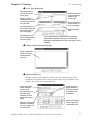
9.1
Print Settings......................................................................................................9-2
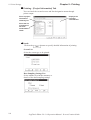
9.1.1 Printing ...................................................................................................................... 9-2
9.1.2 Print Preview ............................................................................................................. 9-6
LogiTouch Editor Ver. 1.0 Operation Manual - Screen Creation Guide
15
Preface
CHAPTER 10: ADVANCED FEATURES
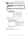
10.1 Filing Data (Recipe) ...................................................................................... 10-2
10.1.1 Filing Data (Recipe) Function ................................................................................. 10-3
10.1.2 Filing Data Setting ................................................................................................... 10-9
10.1.3 Filing Data List ...................................................................................................... 10-12
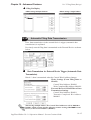
10.1.4 Automatic Filing Data Transmission .................................................................... 10-15
10.1.5 Manual Filing Data Transmission Example .......................................................... 10-16
10.1.6 Manual Filing Data Transmission Example .......................................................... 10-22
10.2 Logging Function ......................................................................................... 10-27
10.2.1 Logging Function .................................................................................................. 10-27
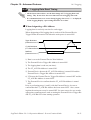
10.2.2 Logging Data Read Timing ................................................................................... 10-31
10.2.3 Data Logging Settings ........................................................................................... 10-32
10.2.4 Display Settings ..................................................................................................... 10-44
APPENDICES
A.1 Error Messages ................................................................................................. A-2
A.2 Troubleshooting ..............................................................................................A-17
A.3 Address Conversion Tables .........................................................................A-19
A.4 Software Trouble Report ..............................................................................A-25
16
LogiTouch Editor Ver. 1.0 Operation Manual - Screen Creation Guide
1
LT EDITOR FUNDAMENTALS
T
his chapter describes LT Editor basic operations such as how to start
and quit the software. It also explains the Project Manager and Screen
Editor areas, which are used for the majority of screen creation work. Also,
a number of tools are introduced here, such as online help, which provide
explanations of LT Editor functions and operations.
1.1
........................................................................ Overview
1.2
...................................................... From Start to Finish
1.3
............................................................ Project Manager
1.4
................................................... Logic Program Editor
1.5
................................................................. Screen Editor
1.6
....................................... LT Editor Manuals and Help
LogiTouch Editor Ver. 1.0 Operation Manual - Screen Creation Guide
1-1
Chapter 1 - LT Editor Fundamentals
1.1
1.1 Overview
Overview
The LT provides I/O control functions and can also be used as an operating
panel and a display.
LT Editor is the LogiTouch integrated development software, providing both
an LT Logic Programming environment and screen creation and editing
capabilities for creating LT display screens.
Programming Functions
Utilizing Window's easy-to-use interface, you can quickly and easily develop logic programs that conform to the IEC 1131-3 standard .
LT Editor provides I/O drivers that can be selected according to the LT type.
Logic programs are developed with the LT Editor's Logic Program Editor.
For more information on the Logic Program Editor, please refer to the online
help. Also, the "Logic Programming Operation Manual" provides tutorials
for learning logic programming procedures as well as providing lists of
instructions and variables used in Logic Programs. It also explains the
operation of the LT main unit.
Drawing Functions
You can create a screen by drawing objects and placing Parts.
A large variety of pre-made Parts and D-Scripts allow you to quickly display
various operations and objects.
A set of logic programs created with the Logic Program Editor and a Part's
display function enable you to make a drawing that corresponds to logic
program operations. For example, you can show the variables on the LT
screen and set a value to the variable using a touch panel switch.
1-2
LogiTouch Editor Ver. 1.0 Operation Manual - Screen Creation Guide
Chapter 1 - LT Editor Fundamentals
1.1 Overview
1.1.1
Prior to Operating the LT
Follow the procedure below to create projects for the LT unit.
1. Preparation – Before using the LT, make sure that you have all the
required hardware and have read all the specifications,
wiring, and installation information.
Chapter 2 – “Specifications” and Chapter 3 – “Installation
and Wiring”
2. Design Screen – Design a screen layout and create a logic program.
3. Install the LT Editor – Install the LT Editor on a PC.
LogiTouch Editor CD Jacket (included with the LT Editor)
4. Develop Logic Program – Use the LT Editor to develop a logic program
and set the operation mode.
LogiTouch Editor Operation Manual – Logic Programming
Guide
5. Create Screen/Run Screen Setup – Use the LT Editor to set up the
screen and parts based on your screen design.
LogiTouch Editor Operation Manual – Screen Creation
Guide
6. Transfer the Screen Data and a Logic Program – Use the LT Editor on
your PC to transfer the data and a logic program to the LT
unit.
LogiTouch Editor Operation Manual – Screen Creation
Guide
7. Monitor Logic Program – Check the transferred logic program through
the monitor feature of the LT Editor.
LogiTouch Editor Operation Manual – Logic Programming
Guide
8. Initialize the LT – Initialize the LT, based on how you will use it.
Chapter 6 – “Initializing the LogiTouch” and LT Editor
External Device Connection Manual
9. Operation – Run the LT by connecting it to an External Device.
LT Editor External Device Connection Manual
LogiTouch Editor Ver. 1.0 Operation Manual - Screen Creation Guide
1-3
Chapter 1 - LT Editor Fundamentals
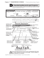
1.2
1.2 From Start to Finish
From Start to Finish
This section describes the LT Editor program’s operation flow from start to
finish.
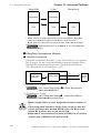
Usage Pattern
Create/Edit a
Create/Select a
Create/Edit a
Logic Program
Start → project file with the → with the Logic → screen with the
Project Manager.
Screen Editor.
Program Editor.
1.2.1
Save the project,
→ and quit the
Project Manager.
Getting Started
Starting LT Editor
The following explanation assumes your PC is turned on and the Windows
desktop has appeared.
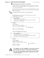
PROCEDURE
REMARKS
(1) Click on the [Start] button, and point to the
[Programs] - [LogiTouch] menu. Then, click on the
[1. Project Manager] command.
If you double-click directly on a
previously made project file (*.lte
file) in Windows Explorer, LT Editor will automatically start.
(2) The Project Manager starts.
At start-up, a splash will appear.
Click on the splash screen to close
it.
Splash
screen
1-4
LogiTouch Editor Ver. 1.0 Operation Manual - Screen Creation Guide
Chapter 1 - LT Editor Fundamentals
1.2 From Start to Finish
PROCEDURE
REMARKS
When 256 colors is selected on the
[Display Properties] screen of the
Control Panel, the display of the
Project Manager may change, but
its functioning will not be affected.
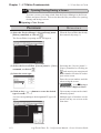
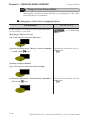
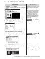
1.2.2
Creating/Selecting/Saving a Project
A project file (LTE file) normally contains multiple screens and a logic
program intended for the operation of a certain system. LT Editor creates
one project file for the operation of one system, enabling system management by project file units.
After you have transferred a project file and set up an LT, you can transfer
updated logic programs individually to the LT.
Creating a New Project
When you create a new project, you must designate the LT and External
Device information, according to your current application.
LT Type
Select your type of LT.
LogiTouch Series
If your LT will be installed vertically instead of horizontally, be sure to
select a vertical type LT. The Screen Editor will automatically create a
vertical drawing area for you.
LT machine type
Type-A1
Type-A2
Type-B
Type-C
LT type of project
LogiTouch Type-A
LogiTouch Type-B
LogiTouch Type-C
External Device Type
Select the type of External Device to be connected to your LT unit.
This setting is required only when the LT is a Type-C.
LogiTouch Editor Ver. 1.0 Operation Manual - Screen Creation Guide
1-5
Chapter 1 - LT Editor Fundamentals
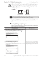
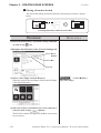
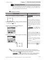
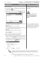
PROCEDURE
1.2 From Start to Finish
REMARKS
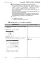
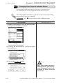
(1) Select the Project Manger's [Project] menu - [New]
command, or click on
.
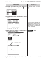
(2) Enter a description and select the LT (Display) and
External Device. Then, click on
.
When entering a description, you
can use up to 60 single-byte characters.
To set the External Device, see “LT Editor External Device Connection Manual”.
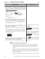
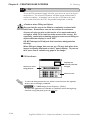
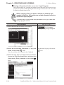
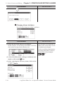
(3)The LT Editor will then ask you if you wish to create
a logic program or a screen. If you click on the
button, the Logic Program Editor
will start. If you click on the
button,
the Screen Editor will start. If you click on the
button, you will go back to the Project Manager
Screen.
1-6
1.2.3 Creating/
Editing/Saving a Logic Program, 1.2.4 Opening/Closing/
Saving a screen.
LogiTouch Editor Ver. 1.0 Operation Manual - Screen Creation Guide
Chapter 1 - LT Editor Fundamentals
1.2 From Start to Finish
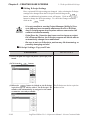
If you attempt to create another project file without saving a newly created
project file, the system asks if you wish to save the current file. If you click on
the
button, the [Save As] dialog box appears. If you click on the
button, the system opens a new screen without saving the current
project file.
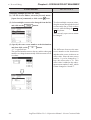
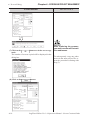
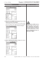
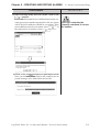
1.2.2
Saving a Project File under a Different Name
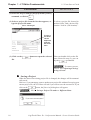
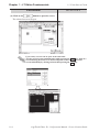
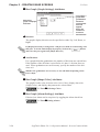
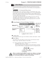
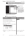
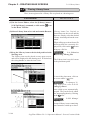
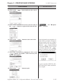
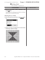
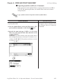
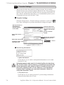
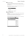
Selecting an Existing Project
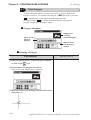
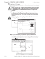
Select the Project Manger's [Project] menu - [Select] command, or click on
. When you select a project, the following setting screen appears:
Used to select the
folder containing the
target project file
Lists the current
folder and existing
project files
Displays the
project file name
selected from the
list.
You can specify
the project file by
typing the file
name.
Displays the project file’s Used to select the
comment and the selected project file type desired
LT unit and External
Devices
File Types
The only project file that can be selected is the one created with the LT
Editor (*.lte).
Double-clicking on the file (project file: *.lte) itself in Explorer automatically
starts LT Editor and opens the file.
LogiTouch Editor Ver. 1.0 Operation Manual - Screen Creation Guide
1-7
Chapter 1 - LT Editor Fundamentals
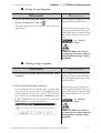
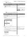
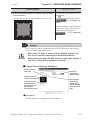
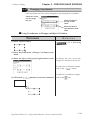
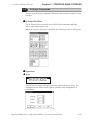
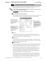
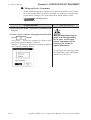
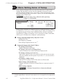
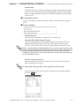
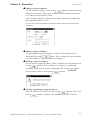
PROCEDURE
1.2 From Start to Finish
REMARKS
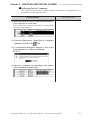
(1) Select the Project Manger [Project] menu’s [Select]
command, or click on
.
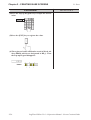
(2) Select a project file from the list that appears, or
type the project file name.
Select “Factory A”
To select a project file located in
another folder, find a desired file
from the “Look in: (File location)”.
To type a
file name
via the
keyboard,
type the
file name
here.
(3) Click on the
file.
button to open the selected When you double-click on the file
name selected in step (2), you can
skip the
command.
To create a screen,
refer to 1.2.4 Opening/Closing/
Saving a Screen.
Saving a Project
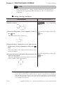
When the data of an existing project file is changed, the changes will be automatically saved.
However, if you attempt to create a another new project file without first saving your
current project file, the LT Editor will ask if you wish to save the current file. If you
button, the [Save As] dialog box will appear.
click on the
1.2.2
1-8
Saving a Project File under a Different Name
LogiTouch Editor Ver. 1.0 Operation Manual - Screen Creation Guide
Chapter 1 - LT Editor Fundamentals
1.2 From Start to Finish
Saving a Project File under a Different Name
You can save an existing project file under a different name or with different LT
type/External Device settings.
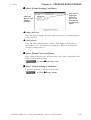
PROCEDURE
REMARKS
(1) Select the [Project ] menu - [Save As ] command in
the Project Manager.
(2) The comment, LT type and External Device of the
currently opened project file are displayed.
Enter the desired file name, and enter the items to be
changed.
The file name can contain up to 255
characters (including the path-name
and extension.)
Before changing the LT type,
check the preset data, since
the drawing area and functions vary depending on the
type of the LT unit.
4.2.6 Changing a
Project’s LT Type
(3) Click on the
button to save the file.
If a project file with the same name exists, LT Editor
will ask if you want to replace (overwrite) the existing
project file with the project file you are attempting to
save.
button. If you do not wish to
If so, click on the
overwrite the existing project file, click on the
button.
Once the External Device is
changed, you must change
the addresses of the Parts,
D-Scripts and alarms, and
perform the LT system setup
again.
4.2.7 Changing
Your Project’s External Device
To open another
project file, see “1.2.2 Creating a New Project or Selecting
an Existing Project”.
To close LT EDITOR for Windows, see “1.2.5 Quitting LT Editor for Windows”.
LogiTouch Editor Ver. 1.0 Operation Manual - Screen Creation Guide
1-9
Chapter 1 - LT Editor Fundamentals
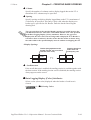
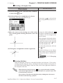
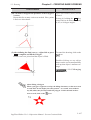
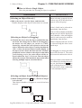
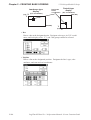
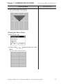
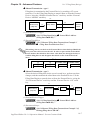
1.2 From Start to Finish
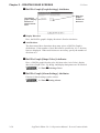
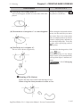
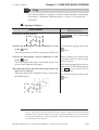
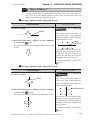
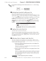
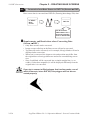
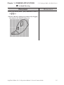
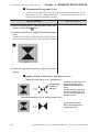
• When a Vertical LT unit is replaced with the horizontal type, or
vice-versa, the displayed screen will rotate 90° relative to the
original data. In this case, you must edit the displayed data
using the [Rotate] command. After editing, be sure to check
the displayed data.
Example)
Horizontal type
1.2.3
ABC
ABC
Vertical type
Creating/Editing/Saving a Logic Program
To create a logic program, you must move from the Project Manager to the
Logic Program Editor. Only one logic program can be created for one
project.
Creating/Editing a Logic Program
When the Logic Program Editor is started, the logic program being created
in the current project file is displayed.
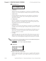
PROCEDURE
REMARKS
(1)Select the Project Manager's [Controls] menu-[Create/Edit Controls] command, or click on
.
The Logic Program Editor starts.
(2)Create/Edit a logic program.
You can insert a rung and instructions as well as set I/O
configuration.
1-10
For details on logic program development, please refer to the "Logic
Programming Operation Manual".
LogiTouch Editor Ver. 1.0 Operation Manual - Screen Creation Guide
Chapter 1 - LT Editor Fundamentals
1.2 From Start to Finish
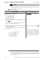
Saving a Logic Program
PROCEDURE
REMARKS
(1) Select the Logic Program Editor's [File] menu-
After saving the program, the Logic
Program Editor remains open.
[Save(s)] command, or click on
.
The logic program you are saving will replace the existing program.
When saving a logic program, variables registered with the Logic Program Editor will be registered with
the Symbol Editor as Logic symbols.
4.2.5 Symbol
Editor
When variables are used in
a drawing, be sure to make a
drawing after saving a logic
program.
Closing a Logic Program
PROCEDURE
REMARKS
(1) Select the Logic Program Editor's [File] menu - [Exit]
command.
You can also close the logic program by clicking on the x button at
the upper right corner of the Logic
Program Editor.
(2) The Logic Program Editor will close.
If you attempt to close an updated logic program without saving it, the system asks if you wish to save the
current program. If you click on the
button,
the system saves the updated data. If you click on the
When saving a logic program, variables registered with the Logic Program Editor will be registered with
the Symbol Editor as Logic symbols.
button, the system closes the Logic Program
Editor without saving the updated data.
4.2.5 Symbol
Editor
When variables are used in
a drawing, be sure to make a
drawing after saving a logic
program.
LogiTouch Editor Ver. 1.0 Operation Manual - Screen Creation Guide
1-11
Chapter 1 - LT Editor Fundamentals
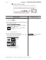
1.2.4
1.2 From Start to Finish
Opening/Closing/Saving a Screen
To create a screen, you must switch from the Project Manager to the Screen
Editor, and open a screen. This section describes the procedures for opening,
closing, and saving a screen.
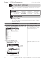
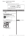
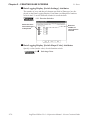
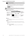
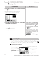
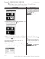
Opening a New Screen
PROCEDURE
REMARKS
(1) Select the Project Manger's [Screen/Setup] menu [Editor] command, or click on
.
When the Screen Editor has already
been started, skip step (1).
The Screen Editor’s opening screen will appear.
(2) Select the Screen Editor [Screen] menu’s - [New]
command, or click on
.
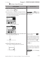
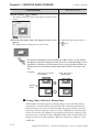
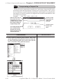
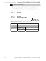
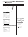
(3) Select the screen type.
Selecting the [Screen] menu’s [Open] command or clicking on
and entering an unregistered
screen number can also be used to
open a new screen.
Enter the screen number and title
when saving the screen.
1.2.4 Saving a
Screen under a Different Name
(4) Click on the
type of screen.
1-12
button to create the desired
Up to twenty screens can be simultaneously opened.
A screen corresponding to the designated LT type will
appear.
Multiple types of windows can be
opened on any one screen at the
same time.
LogiTouch Editor Ver. 1.0 Operation Manual - Screen Creation Guide
1.2 From Start to Finish
Chapter 1 - LT Editor Fundamentals
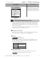
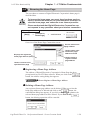
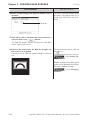
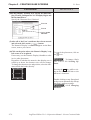
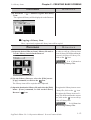
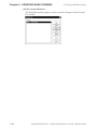
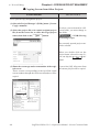
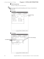
Opening a Previously Saved Screen
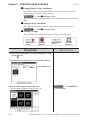
PROCEDURE
(1) Select the [Screen/Setup] menu’s - [Editor] command, or click on
in the Project Manager.
The Screen Editor’s opening screen will appear.
REMARKS
When the Screen Editor has already
been started, skip step (1).
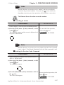
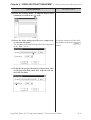
(2) Select the [Screen] menu’s - [Open] command or click
on
.
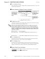
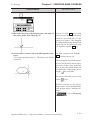
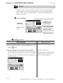
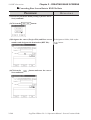
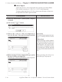
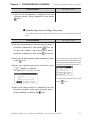
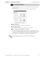
(3) Use this screen to select a screen name from the list,
or select the screen type and enter the screen number.
When checking the [Preview] check box, the selected
screen image can be viewed in the dialog box.
When you double-click on the desired screen number in step (3), you
can skip the operation of the
button.
If you enter a screen number that
has not been registered in the list, a
new screen will be opened and that
number will be assigned to it.
When selecting multiple screens, a
screen with the smallest screen
number of them will be displayed.
Preview Check Box
LogiTouch Editor Ver. 1.0 Operation Manual - Screen Creation Guide
1-13
Chapter 1 - LT Editor Fundamentals
PROCEDURE
(4) Click on the
1.2 From Start to Finish
REMARKS
button to open the screen.
The selected screen will open.
Up to twenty screens can be open at the same time.
To select several screens simultaneously, while pressing the Shift key, click on a
screen and drag the mouse over desired adjacent screens; or, you can select
screens individually by clicking on them while pressing the Ctrl key.
1-14
LogiTouch Editor Ver. 1.0 Operation Manual - Screen Creation Guide
Chapter 1 - LT Editor Fundamentals
1.2 From Start to Finish
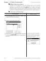
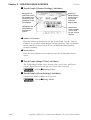
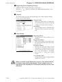
Saving a Screen
PROCEDURE
REMARKS
(1) Select the [Screen] menu- [Save] command, or click
on
in the Screen Editor
After the screen is saved, it will remain open.
The current screen will be saved, overwriting the previous one.
When you attempt to save a new
screen, the [Save As] dialog box
will appear.
1.2.4 Saving a
Screen under a Different Name
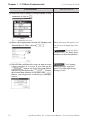
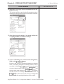
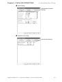
Saving a Screen under a Different Name
PROCEDURE
REMARKS
(1) Select the [Screen] menu - [Save As] command in
the Screen Editor.
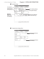
(2) The type, number, and title of the current screen is
displayed.
A “,” (comma) cannot be used in a
description.
You can change the setting of a desired item; however,
the screen’s type cannot be changed.
button to register the above
After the screen is saved, it will
remain open.
If a screen with the same number exists, the system asks
if you want to replace the existing screen with the screen
you are attempting to save.
If so, click on the
button. If you do not wish to
overwrite the existing screen, click on the
button.
If the screen is saved as a different
screen number, the screen of the updated number will be displayed.
(3) Click on the
settings.
LogiTouch Editor Ver. 1.0 Operation Manual - Screen Creation Guide
1-15
Chapter 1 - LT Editor Fundamentals
1.2 From Start to Finish
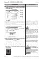
Closing a Screen
PROCEDURE
REMARKS
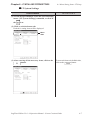
(1) Select the [Screen] menu - [Close] command in the
Screen Editor.
You can also close the screen by
clicking on the button at the upper right corner of the window
(drawing area).
(2) The screen will close.
If you attempt to close an updated screen without saving
it, the system asks if you wish to save the current screen.
If you click on the
button, the system saves
the updated data. If you click on the
button,
the system closes the screen without saving the updated
data.
When you attempt to save a new
screen, the [Save As] dialog box appears.
1.2.4 Saving a
Screen under a Different Name
Quitting the Screen Editor
PROCEDURE
REMARKS
(1) Select the [Screen] menu - [Exit] command, or click
on
in the Screen Editor.
(2) The Screen Editor will close.
If you attempt to close the Screen Editor without first
saving the currently edited screen, LT Editor asks if you
wish to save the updated screen. If you click on the
button, LT Editor saves the updated data. If
you click on the
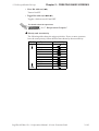
button, LT Editor quits the
Screen Editor without saving the updated data.
1-16
When you save a new screen, the
[Save As] dialog box appears.
1.2.4 Saving a
Screen under a Different Name
LogiTouch Editor Ver. 1.0 Operation Manual - Screen Creation Guide
Chapter 1 - LT Editor Fundamentals
1.2 From Start to Finish
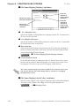
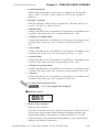
1.2.5
Quitting LT Editor
Quitting LT Editor
PROCEDURE
REMARKS
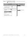
(1) Select the [Project] menu - [Exit] command, or click
When you are working on the
Screen Editor or the Logic Program
Editor, quit the Screen Editor or the
Logic Program Editor, or select the
Project Manager.
on
in the Project Manager.
(2) The Project Manger will quit.
If you attempt to close the Project Manager without saving the currently opened screen’s updated data, LT Editor asks if you wish to save your project’s data. If you
click on the
button, LT Editor saves the updated data. If you click on the
button, LT Editor quits (closes) without saving the updated data.
1.2.4
the Screen Editor
Quiting
Saving the screen
Saving the Logic Program
LogiTouch Editor Ver. 1.0 Operation Manual - Screen Creation Guide
1-17
Chapter 1 - LT Editor Fundamentals
1.3
1.3 Project Manager
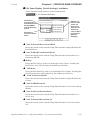
Project Manager
All LT Editor system level settings and functions are controlled via the
Project Manager.
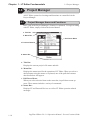
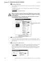
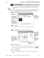
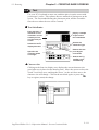
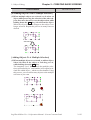
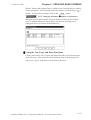
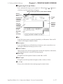
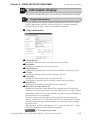
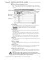
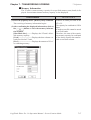
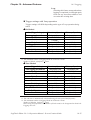
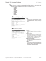
1.3.1
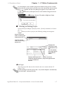
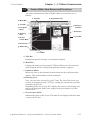
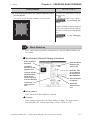
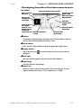
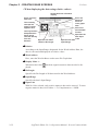
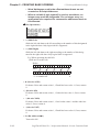
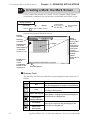
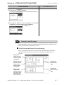
Project Manager Areas and Functions
Here, each of the Project Manager’s features is explained. To begin working
with LT Editor, simply click on the desired button.
a. Title Bar
b. Menu Bar
c. Pull-Down Menu
e. Function Buttons
d. Status Bar
a. Title Bar:
Displays the current project’s file name and title.
b. Menu Bar:
Displays the menus used for the operation of LT Editor. When you select a
desired menu using the mouse or keyboard, one of the pull-down menus
described below will appear.
c. Pull-Down Menu:
When you select a desired item on the menu bar, its pull-down menu appears. These menus includes a variety of commands.
d. Status Bar:
Displays LT and External Devices as well as LT Editor operation related
messages.
1-18
LogiTouch Editor Ver. 1.0 Operation Manual - Screen Creation Guide
1.3 Project Manager
Chapter 1 - LT Editor Fundamentals
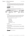
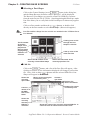
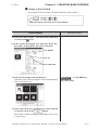
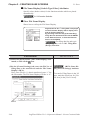
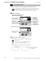
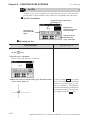
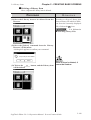
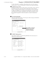
e. Function Buttons
These buttons indicate the LT Editor program’s main functions (e.g. creating
screens, alarms, printing, etc.). You can start each function by simply clicking on that function’s button. You can also start these functions by selecting
the corresponding command from the Project Manager’s pull-down menu.
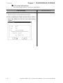
Creates a new project
Selects an existing project
Makes initial
setting of the LT
main unit
Monitors the
logic program
Displays a list
of variables
Creates a logic
program with
the Logic
Program Editor
Creates a
screen with the
Screen Editor
Sets I/O configuration
Creates alarms with
the Alarm Editor
Transmits screen and
logic program to the LT
Quits the LT Editor
LogiTouch Editor Ver. 1.0 Operation Manual - Screen Creation Guide
1-19
Chapter 1 - LT Editor Fundamentals
1.4
1.4 Logic Program Editor
Logic Program Editor
Logic programs are created with the Logic Program Editor.
The online help provides you with detailed information on the Logic Program Editor.
Also, the "Logic Programming Operation Manual" explains procedures
using tutorials. It also explains instructions and settings required for combining the LT main unit with the LT Editor.
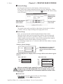
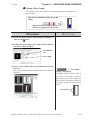
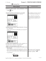
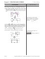
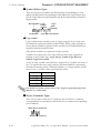
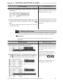
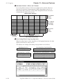
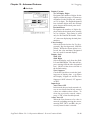
1.4.1
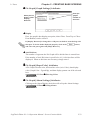
Logic Program Editor Item Names and Functions
Here, basic item names and functions of the Logic Program Editor main
window are explained.
For details, please refer to online help.
a. Title Bar
c. Pull-down Menu
b. Menu Bar
d. Tool Bar
e. Programming
Area
f. Status Bar
a. Title Bar
Displays the project file name, screen number and title.
b. Menu Bar
Displays the menus used to operate LT Editor. When you select a desired
menu using the mouse or keypad, the pull-down menu (c) appears.
c. Pull-down Menu
When you select a desired menu from the menu bar, the pull-down menu
appears. This menu includes various commands.
d. Tool Bar
The Tool Bar provides icons representing such commands as Creating/
Editing a Logic Program and RUN/STOP. Clicking one of these icons
performs that command. The Tool Bar can either be hidden or displayed.
1-20
LogiTouch Editor Ver. 1.0 Operation Manual - Screen Creation Guide
1.4 Logic Program Editor
Chapter 1 - LT Editor Fundamentals
e. Programming Area
Creates a logic program.
The entire program may not display depending on the size of the window or
program. In such cases, use the window’s scroll bar to change the display
area.
f. Status Bar
Displays information on the edited logic program and messages concerning
the operation.
LogiTouch Editor Ver. 1.0 Operation Manual - Screen Creation Guide
1-21
Chapter 1 - LT Editor Fundamentals
1.5
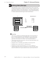
1.5 Screen Editor
Screen Editor
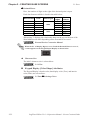
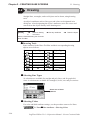
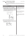
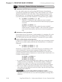
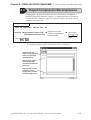
To create a screen, start the Screen Editor via the Project Manager.
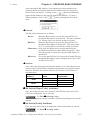
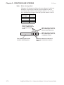
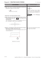
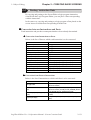
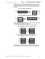
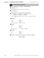
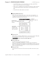
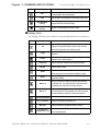
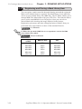
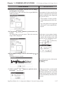
There are three types of screens used for different purposes; Base Screen,
Mark Screen and Image Screen.
Screen Screen
Type Number
Contents
This screen is displayed when the LT is in RUN mode.
B1 to Shared drawings and Active images loaded on another
B8999 base screen can be used. One part of a Base Screen can
be registered as a window.
M ark
Used to create marks and foreign characters on a 48 x 48
M 1 to
(M )
dot screen. These marks and foreign characters are
M 8999
Screen
displayed as still or Active images on a Base Screen.
Bitmap image data can be registered here as LT screen
Image (I) I1 to
data. Image screens are displayed as still or Active
Screen I8999
images on a Base Screen.
Base(B)
Screen
Maximum Size
per Screen
Approx. 16 KB
576 bytes max.
Approx. 58 KB
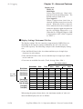
• Although screen files can be numbered from 1 to 8999, the maximum
number of screens that can be created for and used by a LT depends on
your PC's hard disk capacity and the amount of RAM (memory)
available.
• The number of screens that can be transferred to the LT will depend on
how much internal memory the LT has. The actual screen size and
total number of transferable screens can be viewed in the "Project
Manager" window by selecting the [Project] menu, and then [Project
Information].
4.4.1
1-22
Project Information
LogiTouch Editor Ver. 1.0 Operation Manual - Screen Creation Guide
Chapter 1 - LT Editor Fundamentals
1.5 Screen Editor
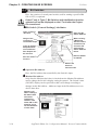
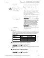
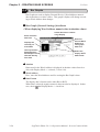
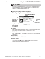
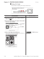
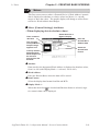
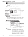
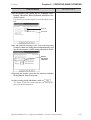
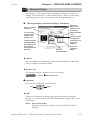
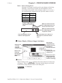
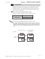
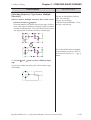
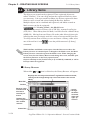
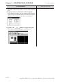
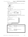
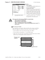
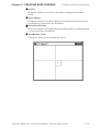
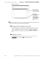
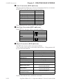
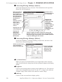
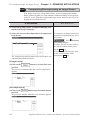
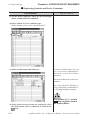
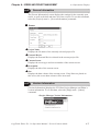
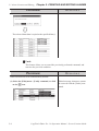
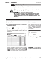
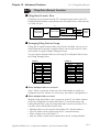
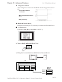
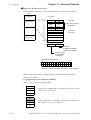
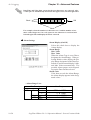
1.5.1
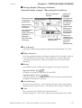
Screen Editor Item Names and Functions
The names and functions of the LT Editor editor’s screen items are as
follows:
a. Title Bar
k. Screen Data List
b. Menu Bar
g. Tool Bar
j. Selection
Tool Box
c. Pull-down
Menu
i. Zoom Box
d. Drawing
Area
h. Tool Bar
e. Screen
Center Mark
f. Grid Points
g. Status Bar
h. Tool Bar
a. Title Bar
Displays the project file name, screen number and title.
b. Menu Bar
Displays the menus used to operate LT Editor. When you select a desired
menu using the mouse or keypad, the pull-down menu (c) appears.
c. Pull-down Menu
When you select a desired menu from the menu bar, the pull-down menu
appears. This menu includes various commands.
d. Drawing Area
Here, you can create a screen for your LT unit. The size of the screen you
see here is designated via the “LT Type” setting you entered when you first
created the project file.
Depending on the size of your PC’s display, the screen’s entire display area
may not be displayed. In this case, simply scroll up or down to view the
entire screen.
e. Screen Center Mark
Indicates the center of the screen. This mark is not displayed when the data
is sent to the LT unit.
LogiTouch Editor Ver. 1.0 Operation Manual - Screen Creation Guide
1-23
Chapter 1 - LT Editor Fundamentals
1.5 Screen Editor
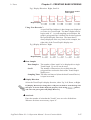
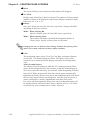
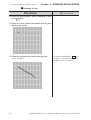
f. Grid Points
Used as reference points when you draw or paste an object in the drawing
mode. Grid points will not be displayed on the LT unit’s screen. The Option
area’s “Snap” function allows you to position your screen objects using a
pre-made grid. You can also set the interval and display ON/OFF status of
the grid points.
2.7.1 Grid/Snap
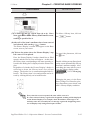
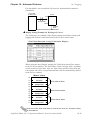
g. Status Bar
Displays information related to the current screen and provides messages
explaining the screen operation you are currently performing.
Coordinates
of current
mouse
position
Amount of Screen
memory currently
used (Ratio of used
screen area to entire
screen)
Description of the
currently selected
command
Display area’s
Project’s magnification/
External reduction ratio
Device
h. Tool Bar
The Tool Bar provides easy to use icons for drawing and editing. Clicking
on one of these icons performs that command. The Tool Bar can either be
hidden or displayed, and individual Tool Bar areas can be moved freely
around the Screen Editor screen, i.e. top, bottom, left, or right.
The following Tool Bar areas are available:
Main Tool Bar
Edit Tool Bar
Draw Tool Bar
Option Tool Bar
Grid/Snap Tool Bar
Parts Tool Bar
Parts State Change Tool Bar
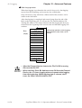
i. Zoom Box
Shows the cursor’s current position at three times magnification.
j. Selection Tool Box
Used to select objects to be edited (Parts and figures). Using the commands
included in this tool box, you can select objects using a variety of methods.
k. Screen Data List
Lists the settings and layout conditions of the objects (Parts and figures) that
have been arranged on the screen. You can select a desired object from the
list.
2.7.4 Screen Data List
1-24
LogiTouch Editor Ver. 1.0 Operation Manual - Screen Creation Guide
Chapter 1 - LT Editor Fundamentals
1.5 Screen Editor
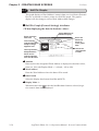
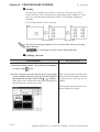
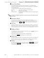
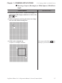
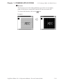
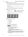
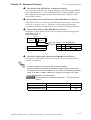
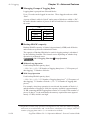
1.5.2
Display Area (50%, 100%, 200%)
You can enlarge or reduce the drawing area by selecting a magnification/
reduction ratio.
To change the display area, select the
or
icon on the tool bar, or
select the [50%], [100%], or [200%] command from the [View] menu.
Zoom out
Zoom in
Zoom out: Used to reduce the current display area to 50%.
Zoom in: Used to enlarge the current display area to 200%.
In the [50%] display mode, the created screen data is reduced. In this case,
the displayed screen data may be different from the actual data. We recommend you to use a [100%] or larger display area.
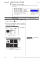
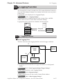
1.5.3
Tool/Icon Display
The Parts tool box, tool bar, and status bar can be designated as either shown
(displayed) or not shown (not displayed). Each time you select the [View]
menu's [Screen Data Box], [Status Bar], or [Zoom Box], as well as the
[Tool Bar] command's [Main], [Edit], [Draw], [Option], [Grid/Snap],
[Parts], or [Parts State Change] sub-commands, these View/Hide settings
will toggle ON or OFF.
LogiTouch Editor Ver. 1.0 Operation Manual - Screen Creation Guide
1-25
Chapter 1 - LT Editor Fundamentals
1.6
1.6 LT Editor Manuals and Help
LT Editor Manuals and Help
While you are learning how to use the LT Editor software, please refer to the
following learning aids:
· Related User Manuals
· On-line Help Topics
· Digital’s Home Page
For the help concerning the operation of the Windows operating system, see
the Windows software’s manuals and help screens.
Using LT Editor Manuals
The following manuals have been created for the LT Editor software.
CD Jacket:
Describes LT Editor's installation procedures and
system requirements.
Drawing Operation Manual:Provides detailed explanation of operating
procedures for all LT Editor's commands except
those for logic program development.
Logic Programming Operation Manual: Provides tutorials to help you to
learn operating procedures of Logic Program
Editor. Also describes operation of the LT main
unit as well as instructions and variables used in
logic programs.
Parts List:
Describes the LT Editor's pre-made Parts and
symbols.
External Device Connection Manual: Describes the methods for connecting
the LT to the external devices of various manufacturers and system requirements.
Using the Help Feature
If you have any problems or questions during LT Editor operation, you can
view the explanations for each feature and setting via each window’s Help
button, or from the main menu’s Help feature.
The Help explains settings of each window and dialog box, instructions and
functions of a logic program as well as each driver's setting.
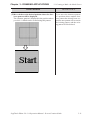
Using the Home Page
You can obtain the latest LT Editor information by addressing the Digital
Electronics Corporation Home Page on the LT Editor screen.
1-26
LogiTouch Editor Ver. 1.0 Operation Manual - Screen Creation Guide
1.6 LT Editor Manuals and Help
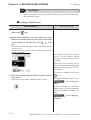
1.6.1
Chapter 1 - LT Editor Fundamentals
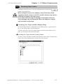
Browsing Help Topics
To display the help screen, select the [Help] menu or click on the
button in the dialog box.
· When multiple screens are loaded or many Parts have been
registered on the screens, the PC’s system memory may not be
sufficient to display the help screen.
· If you jump from one topic to another on the help screen, an
error message may be displayed. When this happens, simply
quit and then re-start help.
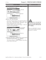
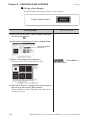
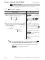
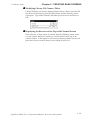
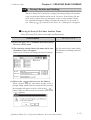
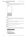
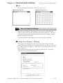
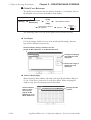
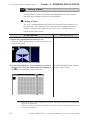
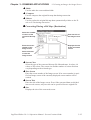
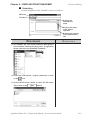
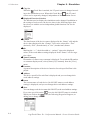
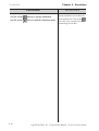
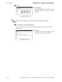
Searching for a Topic and then Display Help
Select the [Help Topics] command from the [Help] menu, or press the [F1]
key. A list of help topics will be displayed.
You can search for a topic by either trying to find it from the table of contents, or entering a keyword for that topic.
Searching for a Topic from the Contents Menu
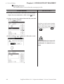
To select a topic from the contents menu, double-click on the [Contents] tab.
Follow the screen instructions to search for a desired topic.
LogiTouch Editor Ver. 1.0 Operation Manual - Screen Creation Guide
1-27
Chapter 1 - LT Editor Fundamentals
1.6 LT Editor Manuals and Help
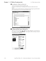
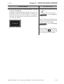
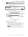
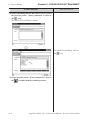
Searching for a Topic by a Keyword
To enter a keyword, click on the [Index] tab.
Search for a desired topic according to the instruction indicated on the
screen.
(When you enter initial characters of the keyword, the topics specified with
these initial characters are also automatically listed)
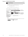
Calling up Help from a Dialog Box
When you click on the
button in the dialog box or press the [F1]
key during execution of a command, a description of the currently-executed
command will be displayed.
1-28
LogiTouch Editor Ver. 1.0 Operation Manual - Screen Creation Guide
Chapter 1 - LT Editor Fundamentals
1.6 LT Editor Manuals and Help
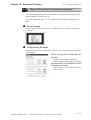
1.6.2
Browsing the Home Page
The procedure to connect to Digital Electronic Corporation's home page is
described here.
· To browse the home page, you must have hardware environment to access the Internet. You also must have a browser to
view the home page, and subscribe to an Internet provider.
· Please understand that Digital Electronics Corporation cannot respond to any questions about your Internet connection.
Operating procedures
[Help]
→ [Connect to
Home Page]
→ Add/Edit/Delete
→
Click on the
button.
Overview of the Home Page Connection screen:
Used to add a home
page address
Used to edit a registered home page
address and title
Displays the registered
home page address (title)
Used to delete a
registered home
page address
Used to connect to the
specified home page
Registering a Home Page Address
The address of Digital Electronics Corporation’s Home Page has been
preregistered in your LT Editor software. When you click on the
button, the address setting dialog box appears.
How to Register a Home Page Address
Deleting a Home Page Address
Any registered home page address can be deleted. When you select the
home page address to be deleted and click on the
button, the
confirmation dialog box appears. If you click on the
button, the
selected home page address will be deleted. If you click on the
button, the deleting operation will be canceled.
LogiTouch Editor Ver. 1.0 Operation Manual - Screen Creation Guide
1-29
Chapter 1 - LT Editor Fundamentals
1.6 LT Editor Manuals and Help
Editing a Home Page Address
The registered home page address or title can be changed. When you select the home
page address to be edited and click on the
button, the address setting dialog
box appears (same as for the home page addition procedure), enabling you to change
the title and address of the home page. If Digital Electronics Corporation’s home
page address is changed in the future, please edit the currently registered address.
Connecting to the Home Page
PROCEDURE
REMARKS
(1) Select the [Help] menu - [Connect to Home Page]
command in the Project Manager.
(2) Select the target home page address.
button to start connection.
(3) Click on the
The browser is started, and you will be connected to the
home page.
1-30
If a browser has not been specified,
the following dialog box appears.
Specify a browser, and re-start the
connecting procedure.
LogiTouch Editor Ver. 1.0 Operation Manual - Screen Creation Guide
Chapter 1 - LT Editor Fundamentals
1.6 LT Editor Manuals and Help
How To Register a Home Page Address
PROCEDURE
REMARKS
(1) Select the [Help] menu - [Connect to Home Page]
command in the Project Manager.
(2) Click on the
button.
(3) Enter a home page title and address to be registered
and click on
.
The specified home page address will be registered.
LogiTouch Editor Ver. 1.0 Operation Manual - Screen Creation Guide
1-31
Memo
1-32
LogiTouch Editor Ver. 1.0 Operation Manual - Screen Creation Guide
2
CREATING BASE SCREENS
T
o create Base screens, the Editor area’s Part, Draw and Menu Bar
commands can all be used. Also, Edit commands can be used to
modify any Parts or objects that you have created. In addition to
editing these screen objects, the procedures for registering Library
Items and Windows are also explained.
2.1
................................................................................ Parts
2.2
.......................................................................... Drawing
2.3
................................................................ Object Editing
2.4
......................................................................... Libraries
2.5
.............................................. D-Script/Global D-Script
2.6
............................................................... Data Sampling
2.7
...................................... Efficient Drawing Techniques
2.8
............................................................ DXF Conversion
LogiTouch Editor Ver. 1.0 Operation Manual - Screen Creation Guide
1-1
Chapter 2 - CREATING BASE SCREENS
2.1
2.1 Parts
Parts
Parts such as Switches, Lamps, and Graphs can be placed on Base screens.
Each Part’s attributes such as setting Addresses and colors will be designated via the dialog box. Switches and Lamps can be selected while viewing
their images via the Browser. After designating all the necessary Part attributes, decide their position and size on the object drawing area.
The [Parts] menu’s commands are effective only on Base screens.
Usage Pattern
Decide on
Select the specific
Part
Browser
[Parts] → a type of → Part from the
or
Place it
Specify its
→ Attributes → on the
Screen
Select a desired icon from the Parts Tool Bar.
LT Editor Part Type Summary
Each of the Parts used in LT Editor is listed below.
Icon
2-2
Name
Bit Switch
Function
Used to change a External Device’s Bit
Address data.
Word Switch
Changes a External Device’s Word
Address data.
Function Switch Used to go back to the previous screen,
to switch screens, and to reset the LT.
Lamp
Turns ON or OFF, according to whether
the External Device’s Monitor Bit is ON
or OFF.
Bar Graph
Displays the External Device’s Word
Address data in a bar graph.
Pie Graph
Displays the External Device’s Word
Address data in a pie graph.
Half-Pie Graph
Displays the External Device’s Word
Address data in a Half-Pie graph.
Meter
Displays the External Device’s Word
Address data in a Meter graph.
Trend Graph
Displays the PLC’s Word Address data
as absolute values in a trend graph.
Keypad Display Used to enter a PLC’s Word Address
data.
Alarm Display
When monitored Bits are turned ON, a
list of “Basic” Alarm summary messages
appear that have been previously
registered in the Alarm Editor.
Filing Data
Displays data registered in the Filing
Display
Data list by specifying the
corresponding file number.
Reference
2.1.1 Bit Switches
2.1.2 Word Switches
2.1.3 Function Switches
2.1.4 Lamps
2.1.5 Bar Graphs
2.1.6 Pie Graphs
2.1.7 Half-Pie Graphs
2.1.8 Meters
2.1.9 Trend Graphs
2.1.10 Keypad Display
2.1.11 Alarm Displays
2.1.12 File Name Display
LogiTouch Editor Ver. 1.0 Operation Manual - Screen Creation Guide
Chapter 2 - CREATING BASE SCREENS
2.1 Parts
Icon
Name
Logging Display
Function
Displays External Device data loaded in
the data logging settings by specifying
the address for the corresponding block
number.
Numeric Display Displays the External Device’s Word
Address numeric data as an absolute
value.
Message Display Displays a previously registered
message, according to External Device
Word Address data changes. A
maximum of 16 messages can be
displayed in a single Message Display.
Date Display
Displays the current date, using the LT’s
internal calendar.
Time Display
Displays the current time, using the LT’s
internal clock.
Picture Display
Displays a single registered Library
image (only graphic data), according to
External Device Word Address data
changes. A maximum of 16 different
Library images can be displayed in a
single Picture Display. (One at a time)
Reference
2.1.13 Data Logging
2.1.17 Display
2.1.14 Numeric Displays
2.1.15 Message Displays
2.1.16 Date Displays
2.1.17 Time Displays
2.1.18 Picture Displays
Entering a Comment
If desired, a comment can be entered for a Part.
Applies the
device comment
Up to 20
alphanumeric
(single-byte)
characters can
be entered
Reflection of a Device Comment
If you click on the
[Apply Device Comment] button after entering an
address, the device comment entered using the Symbol Editor is automatically searched for, and the comment corresponding to the entered device
appears in the Description field.
4.2.5 Symbol Editor
LogiTouch Editor Ver. 1.0 Operation Manual - Screen Creation Guide
2-3
Chapter 2 - CREATING BASE SCREENS
2.1 Parts
Entering Addresses
Here, Addresses that are operated for Parts’ functions and that are monitored
are designated.
A variable to be used in a logic program (Logic symbol) can be designated
as a Part's address.
4.2.5 Symbol Editor
When a function requires consecutive addresses and a variable
(Logic symbol) is used as a start address, an integer array must
be designated.
For an integer array, an appropriate size required for consecutive addresses needs to be allocated.
Enter the address data
here
Entering from a keyboard
Click on the address entering field, and the cursor will appear there, which
indicates data entry is now effective. Then, enter device and address data via
the keyboard.
Entering from a pull-down list
Click on the
box next to the Address entering field, and a pull-down list
appears including symbols and Logic symbols selected via the Symbol
Editor and device comments together with corresponding Addresses. Selecting a symbol, Logic symbol or device comment from the list designates an
Address.
2-4
LogiTouch Editor Ver. 1.0 Operation Manual - Screen Creation Guide
Chapter 2 - CREATING BASE SCREENS
2.1 Parts
Entering from the Address Keypad
Click on the [Address Keypad] icon, and the Address Keypad will appear,
allowing you to enter numeric data and addresses on the screen via the
mouse.
When designating a variable for a logic program (Logic symbol) by bit, use
the Logic Symbol Keypad that will be displayed by clicking the [Logic]
button in the Address Keypad window.
Activates the
Address Keypad
To move the Address
keypad to the desired
position, drag its title bar.
[Address Keypad]
To close the pop-up
keypad, click here.
To display the device
names in a list, click here.
Backspace key
Hexadecimal
number entry key
Display
Clear key
{
Enter key
Displays the Logic
Symbol Keypad
[Logic Symbol Keypad]
Designates a Logic
symbol by bit
Returns to the Address
Keypad
Note:
A pull down list
shows Logic
symbols.
The Logic symbol
will be accepted
with a click on the
Enter key.
A Part’s specified address can be entered so that it is displayed during Base
screen creation.
2.9.2 Screen
2.7.2 Property Settings
Regardless of whether addresses are designated as either displayed or not
displayed during Base screen creation, they will not be displayed on the LT
panel after screen transfer.
LogiTouch Editor Ver. 1.0 Operation Manual - Screen Creation Guide
2-5
Chapter 2 - CREATING BASE SCREENS
2.1 Parts
Selecting a Part Shape
Click on the General Settings Area’s
button in the dialog box,
and the Shape Browser (hereafter called “Browser”) will be displayed.
The Browser’s Part Shapes are stored in a Part File (PDB file), separate
from the main Project File (LTE file). Searching through different pre-made
Part files allows you to easily find useful Part Shapes for almost any application.
button, or double-click
Click on a Part number and then the
directly on the Part number to select a Part Shape. (Browser disappears)
Note:
Part File and Part Shape lists for each file are included in the LT Editor Parts
List Manual.
Clicking here scrolls
through the Part
Shapes in this file
The ID number
of the Part
Shape is displayed here.
Reverse video
(highlighting)
indicates it is
selected
Calls up a list of the
other Part files
Shows the ID number of the
currently selected Part Shape
Shows the Path-name of the
currently open Part File
PDB File
button, and a list of the Part files will appear. After
Click on the
clicking on a Part File, the information displayed will change to reflect that
file. Next, click on the
button and the selected PDB File’s Part
Shapes will appear in the Browser.
Shows the
currently
open folder
Lists the
names of all
the PDB
files in this
folder
Shows the
currently
selected
PDB file’s
comment
2-6
Moves to the next higher
file directory level
Creates a
new folder
Displays file
names and details
Displays file names
in summary form
Shows the name of the currently selected PDB file. A
name can also be entered here to select a file
LogiTouch Editor Ver. 1.0 Operation Manual - Screen Creation Guide
Chapter 2 - CREATING BASE SCREENS
2.1 Parts
Note:
When the LT Editor software is first installed, all Part Files will be included
in a folder named PDB and automatically installed in the same directory/
folder as the LT Editor program. If desired, these Part Files can be moved to
other folders and, to find a Part File that has been moved, use the [Look in:]
area to display Part Files located in other folders.
Selecting Colors
Specify Part colors using the Shape/Color setting screen. The setting items
will differ depending on the Part, i.e. the border type, ON/OFF states,
graphs, and label colors.
Tiling patterns can be selected for some of the Parts, Lamps, and Graphs.
Colors
There are 8 colors available in the color bar. Use this bar to select the
foreground (Fg), background (Bg) and other colors. On a monochrome LT
screen, black, blue, green, and cyan will be displayed as black (same as
background); red, magenta, yellow, and white will be displayed as white.
Color LT unit
BK BL GR CY RD MG YL WH
Monochrome LT unit
Black (not White (disdisplayed) played)
LogiTouch Editor Ver. 1.0 Operation Manual - Screen Creation Guide
2-7
Chapter 2 - CREATING BASE SCREENS
2.1 Parts
Blink
, the color bar is displayed in a
When the Blink (Blk) Check Box checked
darker color and the specified Part will blink on the LT’s screen.
Blink Check Box
Note:
When either text characters or Mark backgrounds (Bg) are specified as
Black, and the Blk (Blink) feature is turned on, they will become transparent; so that even when overlaid on other objects, the rear object’s color is also
visible. This function is useful when overlaying text on Switches, Lamps, and
other objects.
For example:
Specifying a Label’s
background color as
Black does not allow you
to see the background
color.
However, specifying the Label’s
background color as Black and
turning on Blk (blink), causes
the background color to become visible.
States
Only Parts which can have two states are displayed with this feature. Display colors for Parts can be specified separately for each state. Click on
either state button to select it, and specify that state’s color using the color
bar.
2-8
LogiTouch Editor Ver. 1.0 Operation Manual - Screen Creation Guide
Chapter 2 - CREATING BASE SCREENS
2.1 Parts
Alarm Settings
In both graph and numeric value displays, Alarms can be set up.
First, click on the [Alarm Settings] tab at the top of the Dialog box. When
checking the Alarm Display box (Check mark appears), the Alarm setting
items will appear.
Sets the Alarm
value’s Format
to fixed or
variable
Sets the minimum
and maximum
Alarm values
Sets the Alarm
colors used
Alarm Type
The Alarm value can be specified as either direct (fixed value) or indirect
(variable value) by simply clicking on the appropriate circle.
Alarm Range
Here, you can specify the maximum and minimum Alarm values.
When the Alarm value has been specified as indirect, the maximum and
minimum values can also be specified as indirect. In this case, the Word
Address number used to store these values will be automatically assigned
continuously from the Word Address currently specified.
The following example uses “n” to denote where the Word Address’ display
data is stored:
<Indirect Alarm Settings>
Word Addresses are automatically allocated in sequence,
starting from the Address designated
<Relationship between display data’s storage address and Alarm register
address>
With 16 Bit data
n
n+1
n+2
Display Data
Data value - Max.
Data value - Min.
With 32 Bit data
n
n+1
n+2
n+3
n+4
n+5
Display Data
Data value - Max.
Data value - Min.
When a variable (Logic symbol) is used as a start address, an
integer array must be designated. For an integer array, an appropriate size required for consecutive addresses needs to be
allocated.
Alarm Color
Here, you can select the colors used for an Alarm display.
2.1 Parts Selecting Colors
LogiTouch Editor Ver. 1.0 Operation Manual - Screen Creation Guide
2-9
Chapter 2 - CREATING BASE SCREENS
2.1 Parts
Creating Labels
Here, a Label means the text characters shown on the faces of the Switch
and Lamp button Parts. Labels can be registered via the Part’s Setting
dialog box.
As with Parts, Label display colors can be created for each of a 2-state Part’s
states; up to 4 lines of text can be used for each state.
<OFF state>
<ON state>
When a lamp’s Text Display changes
(This Switch’s ON/OFF colors are also selected)
The Part must be large enough to display the entire Label.
Enter the characters here
When the Part has
two states, the
appropriate Label
can be selected
with these buttons
switched On/Off.
Copies the characters in the Description field to the
label for the selected state.
Select the
character’s size
Copies the characters to the label for
the Off state.
Selects the
character’s type
Settings required
only when the text
extends to more
than one line.
Select the label’s
color here
Label
Here, you can type in the text displayed on a button. When typing in text,
press the
key to move to a new line. When the [Tracking] check box is
checked (enabled), after the Part has been placed on the screen, if the
Label’s size or position is changed, for either state, the alternate state’s Label
size and position will be also automatically changed. If, however, the
Label’s size and position need to be specified independently for each state,
DO NOT check
this box.
2.3.3 Scaling Up/Down
Copy from Description
The characters entered in the Description filed are copied to the label in the
selected state.
Copy to Off (On) state
When the state is On, the characters entered in the label are copied to the label in
the Off state. When Off, the characters are copied to the label in the On state.
2-10
LogiTouch Editor Ver. 1.0 Operation Manual - Screen Creation Guide
Chapter 2 - CREATING BASE SCREENS
2.1 Parts
State
States are displayed only for Lamps, and for those switches with two states
(ON and OFF). The text displayed for each state can be specified independently. Simply click on either state button to specify its text and colors.
Character Size
Specifies the size of character.
2.2.9 Text
Style (Font)
Specifies the type of character (Normal, Bold, Raised) used in each Label.
2.2.9 Text
Text Color (ON/OFF)
Specifies Label colors.
The default settings are Fg: White, and Bg: Transparent mode (Black + Blk).
Line space
When the text extends to more than one line, set the line space.
Alignment (Justification)
When the text input for a Label exceeds one line, the Alignment icons will
appear. Select Left, or Right justification, or Centering.
Left-justified
Centered
Right-justified
ID Numbers
When creating a Part, an ID number is automatically assigned to the Part
before it is placed on the screen. This number shows how many of that kind
of Part were previously placed on the current screen. When a Part is deleted
from a screen, all following Part numbers will be adjusted downwards.
Example of an ID number
BS-010
Indicates that this Part is a Bit
Switch
(Varies according to the Part)
Indicates the placement/
creation order of the Part; in
this case, it is the 10th.
The ID number is displayed in the title bar at the top of the Setting dialog
box.
LogiTouch Editor Ver. 1.0 Operation Manual - Screen Creation Guide
2-11
Chapter 2 - CREATING BASE SCREENS
2.1 Parts
The ID number can be entered so that it is displayed during Base screen
drawing.
2.7.2 Screen Property Settings
Even if the ID number is entered to be displayed during Base screen drawing, it will not be displayed on the LT panel after screen data transfer.
<ID Number List>
Part Name
Bit Switch
Word Switch
Function Switch
Lamp
Bar Graph
Pie Graph
Half-Pie Graph
Meter
Trend Graph
Keypad Input Display
Alarm Display
File Name Display
Data Logging Display
Numeric Display
Message Display (Operation Mode: Bit)
Message Display (Operation Mode: Word)
Date Display
Time Display
Picture Display (Motion mode: Bit)
Picture Display (Motion mode: Word)
ID Number
BS-**
WS-***
FS-***
LA-***
BA-***
PI-***
HP-***
MT-***
TR-***
KD-***
AL-***
FD-***
LG-***
ND-***
MB-***
MW-***
DD-***
TD-***
LB-***
LW-***
Maximum Number of Automatically Created Part Libraries
When a Part is used in a project, a Part Library will be automatically created
in preparation for data transfer. The number of Part Library items are
limited to 6000 per project. If this number exceeds 6000, all Parts in excess
of 6000 cannot be transferred to the LT. To avoid this, please remember the
following:
1. Automatic Library creation will be performed follows: (per screen)
Switches:
2 (only switches with the Monitor function selected)
Lamps:
2
Messages:
2 to 16 (depending on the number of states used)
Picture Displays : 2 to 16 (depending on the number of states used)
Trends:
1 to 20 (depending on the number of channels)
However, Part Libraries using the same Parts (i.e. Part’s that are the
same size, same attributes, and without labels or other items) will be used
commonly.
For example:
When 30 Switches (Monitor function is selected) and 20 Lamps are
placed on a single Base screen, (30 × 2) + (20 × 2) = 100 Part Library
items will be automatically created. Therefore, 60 of these size
screens can be used in one project('s data).
2-12
LogiTouch Editor Ver. 1.0 Operation Manual - Screen Creation Guide
Chapter 2 - CREATING BASE SCREENS
2.1 Parts
2. When using the same Parts for multiple Base screens, register the Part on
one Base screen and then place it other Base screens using the Load
Screen function. Thus, when multiple Base screens use those Parts, only
one Part Library will be used, thereby reducing the Project File’s size.
Placing a Part in Position
After all of a Part’s attributes have been entered or selected, click on the
desired position on the screen to place the Part.
PROCEDURE
REMARKS
(1)After all of a Part’s attributes have been entered or
selected, click on the
button.
The Part’s outline will appear on the Base screen, next
to your cursor.
(2)Click on the point where the Part’s top left corner is
to be placed.
The selected Part will then appear on the screen.
(3)Adjust the Part’s size, if desired.
Click on the Part to select it, and drag any one of the
handles to change the size of the Part.
To change the size of a Part, move the cursor to a Part
“handle” and click, then drag the “handle” to re-size the
Part, and click again.
2.3.3 Scaling Up/
Down
After placing the Part, doubleclicking on it automatically brings
up its Attribute Setting dialog box.
2.3.15 Changing
Attributes
Depending on the Part, when scaling up or down, one dot error may occur in
the frame width.
E.g.)
9
10
LogiTouch Editor Ver. 1.0 Operation Manual - Screen Creation Guide
2-13
Chapter 2 - CREATING BASE SCREENS
2.1.1
2.1 Parts
Bit Switches
Here, the creation of a touch panel switch, used for turning a specified Bit
ON or OFF, is explained.
If the LT unit is Type C, Bit Switches with the Monitor function
selected will not be displayed on the LT unit after the Project
File transferred.
Bit Switch [General Settings] Attributes
Enter comment
data here
Enter the Bit
Switch Address
Image of the
currently selected Part Shape
When creating
a Bit Switch
with two states,
check this box
and enter the
alternate Bit
Switch Address
below
Calls up the Part
Shape Browser,
where different
Part Shapes can
be selected
Sets the buzzer
to ON/OFF
Sets the switch’s
function
Selects the
Interlock
function state
Operation Bit Address
Here, the Bit Address data controlled by the Switch is input.
Monitor Bit Address
Only after the Monitor check box is checked can the Monitor Bit Address
used to change the Switch’s display setting be entered. The Switch’s state
(ON/OFF) display can be specified so that it will change according to
changes in this Bit Address. Addresses input in the Bit Address area can
also be done here.
Appears only
when creating a
Bit Switch with
two states.
Toggles the
switch’s state
either ON or OFF,
allowing you to
set the attributes
of each state.
2-14
LogiTouch Editor Ver. 1.0 Operation Manual - Screen Creation Guide
Chapter 2 - CREATING BASE SCREENS
2.1 Parts
After entering the Bit Address, if you attempt to perform another area’s
operation before entering the Monitor Bit’s address data, the dialog box
button automatically
shown below will appear. Clicking on the
inputs the Bit Address’s data into the Monitor Bit Address. To enter a
different address, click on the
button and input the desired address.
Function
The Bit Switch functions are as follows.
Bit Set:
When the Bit Switch is pressed, the External Device’s
designated Bit Address is turned ON. This state continues
(i.e. remains ON) even after the switch is released.
Bit Reset:
When the Bit Switch is pressed, the External Device’s
designated Bit Address is turned OFF. This state continues (i.e. remains OFF) even after the switch is released.
Momentary: Only while the Bit Switch is pressed and held is the
specified External Device Bit Address turned ON. Thus,
when the switch is released, the specified Bit Address is
turned OFF.
Bit Invert: Every time the Bit Switch is pressed, the External Device’s
designated Bit Address state is changed (from ON to OFF,
or from OFF to ON).
Interlock
Only when a bit designated via Interlock Address is in a state that has been
selected via [Touch available condition] radio buttons, the switch becomes
effective. Whether the switch is effective in ON state or in OFF state is
selectable here.
Touch Available
Condition
Bit ON
Bit OFF
Interlock Address
Status
ON
OFF
ON
OFF
Touch Available/
Not Available
Touch Available
Touch Not Available
Touch Not Available
Touch Available
Bit Switch [Shape/Color] Attributes
Here, the Switch’s border color (Frame), ON/OFF state colors (On Color,
Off Color), and pattern can be selected.
2.1 Parts Selecting Colors
The color and pattern settings available will differ depending on the switch’s
settings.
Bit Switch [Label] Attributes
Here, the text of the Label to be displayed on the Switch button is entered.
2.1 Parts
Creating Labels
LogiTouch Editor Ver. 1.0 Operation Manual - Screen Creation Guide
2-15
Chapter 2 - CREATING BASE SCREENS
2.1 Parts
Placing a Bit Switch
An example of how to place a Bit Invert switch is shown below.
First press of the Switch
sets M0016
The next press resets M0016
PROCEDURE
REMARKS
(1)Select the [Parts] menu - [Bit Switch] command, or
click on the
icon.
(2)In the [General Settings] screen, input the Bit Address and select the Bit’s Function.
Enter M0016
When the switch’s
state can change,
click here
Set the buzzer to
ON or OFF
Select the Bit
Invert function
(3)Select a Part Shape from the Browser.
If desired, Select the desired color(s) and input a Label
from the Shape/Color and Text areas.
When the Change State function selected, after entering the Bit Address, if you attempt to perform
another area’s operation before entering the Monitor Bit Address, the
dialog box shown below will appear. Click on the
button
to input the same address as used
for the Bit Address. To enter a different address, click on the
button and input the desired address.
2.1 Parts
ing a Part Shape
Select-
(4)After all of a Part’s attributes have been entered or
selected, click on the
button.
The Switch’s outline will appear on the Base screen, next
to your cursor.
2-16
LogiTouch Editor Ver. 1.0 Operation Manual - Screen Creation Guide
Chapter 2 - CREATING BASE SCREENS
2.1 Parts
PROCEDURE
REMARKS
(5)Click on the point where the Switch’s top left corner
is to be placed.
To cancel the placement, click on
icon.
the
If desired, use the Switch’s handles to alter its size.
To change the Part’s size, refer to
2.3.3 Scaling Up/
Down.
Double-clicking on any Part placed
on the screen automatically calls up
that Part’s Attribute Setting dialog
box.
2.3.15 Changing
Attributes
2.1.2
Word Switches
Here, a touch panel switch for setting data to a specified Word Address can
be created.
Word Switch [General Settings] Attributes
Enter Comment
data here
The Word
Switch’s image
appears here
Calls up the Part
Shape Browser.
Parts can be
selected directly
from the Browser
Selects the
Interlock function
Enter the Word
Address you
wish to use
Enter the data
for the Switch
to send to the
Word Address
Sets the buzzer
to ON/OFF
Select the
Switch’s function
Word Address
Here, the desired Word Address is entered.
Constant
Here, number registered to the Word Address is input. The data format is
Decimal (Base 10), and the input range is from -32768 to 32767.
LogiTouch Editor Ver. 1.0 Operation Manual - Screen Creation Guide
2-17
Chapter 2 - CREATING BASE SCREENS
2.1 Parts
Function
The Word Switch’s functions are as follows:
Word Set:
When the Word Switch is pressed, constant data is written
to the External Device’s designated Word Address. Fixed
or default values will be written to the timer, counter, etc.
Add/Sub:
Every time the Word Switch is pressed, the Data value is
added to the data currently in the External Device’s designated Word Address, and the result is then written to the
External Device’s address. If a Data value is positive, the
function will increment, and if it is negative, it will decrement.
Digit (ADD): Every time the Word Switch is pressed, the designated
decimal place’s data will be added by the Constant’s value.
The result will not be carried up to the next digit, so “9”
simply rolls around to “0”. Select the data format from Bin
and BCD.
Digit (SUB): Every time the Word Switch is pressed, the designated
decimal place’s data will be subtracted by the Constant’s
value. The result will not be carried down to the lower
digit, so “9” simply rolls around “0”. Select the data
format from Bin and BCD.
Interlock
Only when a bit designated via Interlock Address is in a state that has been
selected via [Touch available condition] radio buttons, the switch becomes
effective. Whether the switch is effective in ON state or in OFF sate is
selectable here.
Touch Available
Condition
Bit ON
Bit OFF
Interlock Address
Status
ON
OFF
ON
OFF
Touch Available/
Not Available
Touch Available
Touch Not Available
Touch Not Available
Touch Available
Word Switch [Shape/Color] Attributes
Here, a Word Switch’s color, and pattern can be selected.
2.1 Parts Selecting Colors
The color and pattern settings available will differ depending on the
Switch’s settings, such as its shape and Change State condition.
Word Switch [Label] Attributes
Here, the text characters shown (engraved) on the Switch button face are
input.
2.1 Parts Creating Labels
2-18
LogiTouch Editor Ver. 1.0 Operation Manual - Screen Creation Guide
Chapter 2 - CREATING BASE SCREENS
2.1 Parts
Placing a Word Switch
An example of how to place a Word Set Switch is shown below.
When the button is pressed, 34 is sent to D00001
PROCEDURE
REMARKS
(1)Select the [Parts] menu - [Word Switch] command,
or click on the
icon.
(2)In the [General Settings] area, input the Word Address and Constant data, and select a function.
Enter D00001
Enter 34
Select Word Set
(3)Select a Part Shape from the Browser.
If desired, select Colors and input a Label from the Shape/
Color and Label areas.
2.1 Parts
ing a Part Shape
Select-
SW_3D001
(4)After all of the Part’s attributes have been entered
or selected, click on the
button.
The Switch’s outline will appear on the Base screen, next
to your cursor.
LogiTouch Editor Ver. 1.0 Operation Manual - Screen Creation Guide
2-19
Chapter 2 - CREATING BASE SCREENS
2.1 Parts
PROCEDURE
REMARKS
(5)Click on the point where the Switch’s top left corner
is to be placed.
To cancel the placement, click on
the
icon.
If desired, use the Switch’s handles to alter its size.
To c h a n g e t h e
Part’s size, refer to 2.3.3 Scaling
Up/Down
Double-clicking on any Part placed
on the screen automatically calls up
that Part’s attribute settings.
2.3.15 Changing
Attributes
2.1.3
Function Switches
Here, a touch panel with special functions can be created.
Function Switch [General Settings] Attributes
Enter Comment
data here
Select the
Switch’s operation
The Function
Switch’s image
appears here
When “Go To
Screen” is
selected, the
(Go To)
screen’s number and data
format must be
entered
Calls up the Part
Shape Browser.
Parts can be
selected directly
from the Browser
Selects the
Interlock function
state
Function (Switch Operation)
The Function Switch’s attributes are as follows:
Previous Screen:
Go To Screen:
When the Switch is pressed, the currently
displayed screen on the LT will change to
the previously displayed one.
When the Switch is pressed, the currently
displayed screen on the LT will change to
the specified screen. Input the screen
number to be changed (jumped) to. The
Data Format can be either Bin or BCD.
If a screen number is specified in the BCD data format to place the corresponding screen, it is still displayed in the BIN data format when the screen is
closed and then opened.
2-20
LogiTouch Editor Ver. 1.0 Operation Manual - Screen Creation Guide
Chapter 2 - CREATING BASE SCREENS
2.1 Parts
Reset LT:
When the Switch is pressed, the LT will be
reset to the save status as when the LT’s
power was turned ON.
Resetting the LT turns the I/O signal off. Consider this when
designing your system.
File Name Key:
This is a function switch corresponding to
the File Name Display and is the same as
the one that is automatically placed together
with the File Name Display.
Designate the same ID number as the one of
the File Name Display and select a operation mode.
Data Logging Key:
2.1.13 File Name Display
This is a function switch corresponding to
the Data Logging Display and is the same
as the one that is automatically placed
together with the Data Logging Display.
Designate the scroll direction and the
number of lines being rolled up or down.
2.1.14 Data Logging
Display
When this switch is pressed, the LT enters
the OFFLINE mode.
OFFLINE:
Interlock
Only when a bit designated via Interlock Address is in a state that has been
selected via [Touch available condition] radio buttons, the switch becomes
effective. Whether the switch is effective in ON state or in OFF sate is
selectable here.
Touch Available
Condition
Bit ON
Bit OFF
Interlock Address
Status
ON
OFF
ON
OFF
Touch Available/
Not Available
Touch Available
Touch Not Available
Touch Not Available
Touch Available
Function Switch [Shape/Color] Attributes
The Switch’s color, and pattern are selected here.
2.1 Parts Selecting Colors
The color and pattern settings available will differ depending on the switch
shape.
Function Switch [Label] Attributes
Here, the characters shown (drawn) on the Switch button face are entered.
2.1 Parts
Creating Labels
LogiTouch Editor Ver. 1.0 Operation Manual - Screen Creation Guide
2-21
Chapter 2 - CREATING BASE SCREENS
2.1 Parts
Placing a Function Switch
The Screen Switching (Function) Switch’s placement procedure is shown
below.
B1
B10
Pressing this button, shifts to screen B10.
PROCEDURE
REMARKS
(1)Select the [Parts] menu - [Function Switch] command,
icon.
or click on the
(2)Designate the [Function] on the [General Settings] tab.
Select Go To
Screen
Select Bin
Enter 10
(3)Select a Part Shape from the Browser.
If desired, select Colors and input a Label from the Shape/
Color and Label areas.
2.1 Part
ing a Part Shape
Select-
SW_3D001
(4)After all of Part’s attributes have been entered or
selected, click on the
button.
The Switch’s outline will appear in the Base screen, next
to your cursor.
2-22
LogiTouch Editor Ver. 1.0 Operation Manual - Screen Creation Guide
Chapter 2 - CREATING BASE SCREENS
2.1 Parts
PROCEDURE
REMARKS
(5)Click on the point where the Switch’s top left corner
is to be placed.
To cancel the placement, click on
the
icon.
If necessary, use the Switch’s handles to alter its size.
To change the Part’s size, refer to:
2.3.3 Scaling Up/
Down
Double-clicking on any Part placed
on the screen calls up that Part’s Attribute Setting dialog box.
2.3.15 Changing
Attributes
2.1.4
Lamps
Here a lamp is created, which turns ON or OFF according to the External
Device’s Monitor Bit Address state.
· When the LT is Type C, lamps will not display on the LT unless the LT has been connected to the External Device.
· When placing a Lamp, DO NOT overlap it with other objects. If
you do so, it may not be displayed correctly.
Lamp [General Setting] Attributes
Enter comment
data here
Enter the
desired Bit
Address here
Displays the currently selected Part
Calls up the Part
Shape Browser.
Part Shapes can
be selected
directly from here
Changes the
state of the
dialog box’s
switch display
to either ON or
OFF
Bit Address
The Bit Address to be monitored is entered here.
LogiTouch Editor Ver. 1.0 Operation Manual - Screen Creation Guide
2-23
Chapter 2 - CREATING BASE SCREENS
2.1 Parts
Lamp [Shape/Color] Attributes
Here, border colors for both ON and OFF states, and Lamp’s colors and
tiling pattern in each state can be selected.
2.1 Parts Selecting Colors
The color and pattern settings available will differ depending on each lamp
shape.
Lamp [Label] Attributes
Here, the text characters shown on a Lamp button’s face are entered.
2.1 Parts
Creating Labels
Placing a Lamp
The procedures for creating and placing a Lamp are shown below.
When X00017
is ON...
the Lamp
lights up.
PROCEDURE
When X00017
is OFF...
the Lamp
turns off.
REMARKS
(1)Select the [Parts] menu - [Lamp] command, or click
on the
icon.
(2)In the [General Settings] area, enter a Bit Address.
Enter X00017 here
(3)Select a Part Shape from the Browser.
Select Colors and input a Label, if desired.
2.1 Parts
ing a Part Shape
Select-
LM_3D001
2-24
LogiTouch Editor Ver. 1.0 Operation Manual - Screen Creation Guide
Chapter 2 - CREATING BASE SCREENS
2.1 Parts
PROCEDURE
REMARKS
(4)Switch the state of the lamp with the On/Off buttons, and then select Colors and input a Label.
With the Blink check box checked
, and if the Bit is turned ON, the
Lamp will blink. Lamp blinking
can also be seen via the pull down
menu [View]’s [Preview] command.
Switches the
lamp On/Off
2.7.3 Preview
Screen
(5)After all of the Lamp’s attributes have been entered
or selected, click on the
button.
The Lamp’s outline will appear in the Base screen, next
to your cursor.
(6)Click on the point where the Lamp’s top left corner
is to be placed.
To cancel the placement, click on
the
icon.
If necessary, use the Lamp’s handles to alter its size.
To change the Part’s size, refer to
2.3.3 Scaling Up/
Down
Double-clicking on any Part placed
on the screen automatically calls up
that Part’s attribute settings.
2.3.15 Changing
Attributes
LogiTouch Editor Ver. 1.0 Operation Manual - Screen Creation Guide
2-25
Chapter 2 - CREATING BASE SCREENS
2.1.5
2.1 Parts
Bar Graphs
Bar Graphs are used to display External Device’s Word Address numeric
data in absolute or relative values. This graph’s display will change according to Word Address data changes.
Bar Graph [General Settings] Attributes
<When displaying Word Address numeric data in absolute values>
Select absolute or relative
value display
Enter comment
data here
Displays the
currently selected Part
Calls up the Part
Shape Browser.
Part Shapes can be
selected directly
from here
Enter the
desired Word
Address to
store graph
data here
Select the
display data’s
data format
Absolute
Data stored in the Word Address is displayed in absolute values from 0 to
100 (with Display Mode +/- selected, -100 to 100).
Word Address
Here, enter the Word Address used for storing the Bar Graph’s data.
Data Format
The display data’s format can be either Bin or BCD.
When Bin is selected, negative numeric data can also be displayed. In that
case, check
the Display Mode +/- check box.
2-26
LogiTouch Editor Ver. 1.0 Operation Manual - Screen Creation Guide
Chapter 2 - CREATING BASE SCREENS
2.1 Parts
<When displaying External Device Word Address numeric data in relative values>
Select the Relative value display
Enter comment
data here
Used to store the
graph’s data.
Enter the desired
Word Address
Displays the
currently selected Part
Calls up the
Part Shape
Browser. Part
Shapes can be
selected directly from here Specifies data’s Bit
Length
Select the
display data’s
format
Select the data’s
Input Code
Specifies data
Input Range
Relative
According to the Input Range designated for the Word Address’ data, the
data is converted and displayed as relative values.
Word Address
Here, enter the Word Address used for storing the Bar Graph’s data.
Display Mode+/When this check box
displayed.
is checked, negative numeric data can also be
Bit Length
Specifies the Bit Length of data stored in the Word Address.
Input Range
Specifies the data’s Input Range.
Input Code
When No Code is selected, only positive data can be entered. To enter
negative number data, select +/-2’s Complement or +/-MSB.
LogiTouch Editor Ver. 1.0 Operation Manual - Screen Creation Guide
2-27
Chapter 2 - CREATING BASE SCREENS
2.1 Parts
Bar Graph [Graph Settings] Attributes
Only when a
graph with
graduations
has been
selected will
this box
appear.
Enter the
number of
divisions
desired here
Select the
graph’s display
direction
Direction
The graph’s display direction can be specified as either Up, Left, Down, or
Right.
If [Display Direction] is changed for a 3D part, its shade is rotated along with
that part. To let the shade displayed properly, click on the
button,
and select the part again from [Shape Browser].
Axis Divisions
For a graph which has graduations, the number of divisions are entered here.
If the number of the divisions is specified to 10, then 11 division lines are
used. When graduations are not necessary, specify the number of the divisions as 0.
Whether the graduations are necessary or not will differ depending on the
Part’s shape.
Bar Graph [Shape/Color] Attributes
The graph’s border color, division color (Axis Color), display data color
(Graph Color), and display data patterns are selected here.
2.1 Parts
Selecting Colors
Bar Graph [Alarm Settings] Attribute
If desired, an Alarm can be setup here by toggling the Alarm check box.
2.1 Parts
2-28
Setting Alarms
LogiTouch Editor Ver. 1.0 Operation Manual - Screen Creation Guide
Chapter 2 - CREATING BASE SCREENS
2.1 Parts
Placing a Bar Graph
An example of the Bar Graph’s creation and placement procedures are
shown below.
Data stored in D00102 displays on the Bar
Graph
When the value 34 (22h) is stored in
D00102, the graph will look like this:
PROCEDURE
REMARKS
(1)Select the [Parts] menu - [Bar Graph] command, or
click on the
icon.
(2)In the [General Settings] tab, input a Word Address
and select a Data Format.
Enter D00102
here
Select BCD
(3)Select a Part Shape that has graduations from the
Browser.
Here, you can enter Alarm settings and select Colors, if
desired.
BG_3D002U
2.1 Parts
lecting a Part Shape
Se-
If the Bar Graph’s Alarm value is
specified as Variable, a pointer
showing levels will be displayed.
This pointer’s position will move
according to the specified Alarm
value.
Level pointer
LogiTouch Editor Ver. 1.0 Operation Manual - Screen Creation Guide
2-29
Chapter 2 - CREATING BASE SCREENS
2.1 Parts
PROCEDURE
REMARKS
(4)In the [Graph Settings] tab, select the graph’s display direction and input the number of Axis Divisions.
The area to enter the number of the
divisions will appear only for a graph
type which has axis divisions.
Enter 10 here
Select Up
(5)After all of the graph’s attributes have been entered
or selected, click on the
button.
The Bar Graph’s outline will appear on the Base screen,
next to your cursor.
(6)Click on the point where the Bar Graph’s top left
corner is to be placed.
If necessary, use the Bar Graph’s handles to adjust its
size.
To cancel the placement, click on
the
icon.
To change the Part’s size, refer to
2.3.3 Scaling Up/
Down
Double-clicking on any Part placed
on the screen automatically calls up
that Part’s attribute settings.
2.3.15 Changing
Attributes
The Bar Graph’s sizing handles are
located inside the graph.
2-30
LogiTouch Editor Ver. 1.0 Operation Manual - Screen Creation Guide
Chapter 2 - CREATING BASE SCREENS
2.1 Parts
2.1.6
Pie Graphs
Pie Graphs create an area where a External Device’s Word Address data is
displayed as absolute values. The graph’s display will change to reflect
changes in the designated Word Address data.
Pie Graph [General Settings] Attributes
<When displaying the data using absolute values>
Enter comment
data here
Select Absolute or Relative
display
The currently
selected Pie
Graph’s image
appears here
Calls up the Part
Shape Browser.
Parts can be
selected directly
from the Browser
Enter the
Word
Address
used to
store graph
data
Select the
desired
Data Format
Absolute
Data stored in the designated Word Address is displayed in absolute values,
from 0 to 100 (with Display Mode +/- selected, -100 to 100).
Word Address
Here, the Word Address’ location data is entered to show where the desired
data is stored.
Data Format
Select either the Bin and BCD display formats.
Display Mode +/With this check box
checked and the Bin data format is selected, a
negative numeric data can also be displayed.
LogiTouch Editor Ver. 1.0 Operation Manual - Screen Creation Guide
2-31
Chapter 2 - CREATING BASE SCREENS
2.1 Parts
<When displaying the data using relative values>
Select Absolute or Relative
display
Enter comment
data here
Enter the
Word Address to
store graph
data
The currently
selected Pie
Graph’s image
appears here
Calls up the Part
Shape Browser.
Parts can be
selected directly
from the
Specifies the data’s
Browser
effective Bit Length
Select the
desired Data
Format
Specifies the
data Input
Code
Specifies the data
Input Range
Relative
According to the Input Range designated for the Word Address Data, the
data is converted and displayed as relative values.
Word Address
Here, enter the Word Address used to store Pie Graph data.
Display Mode +/When this check box
played.
checked, negative numeric data can also be dis-
Bit Length
Specifies the Bit Length of all data stored in the Word Address.
Input Range
Specifies the data’s Input Range.
Input Code
With No Code selected, only positive numeric data can be entered. To enter
negative numeric data, select either +/-2’s Complement or +/-MSB.
2-32
LogiTouch Editor Ver. 1.0 Operation Manual - Screen Creation Guide
Chapter 2 - CREATING BASE SCREENS
2.1 Parts
Pie Graph [Graph Settings] Attributes
Enter the
graph’s
number of
divisions
Select the Pie
Graph’s (data
display)
Direction
Display
Here, the graph’s data display start point, either Clkws. From Top or Clkws.
From Bottom, can be selected.
If [Display Direction] is changed for a 3D part, its shade is rotated along with
that part. To let the shade displayed properly, click on the
button,
and select the part again from [Shape Browser].
Axis Divisions
The number of segments the Pie Graph will be divided into is entered here.
If the number of Axis Divisions is specified as 10, 10 division lines will be
displayed. When no divisions are necessary, simply enter 0.
Pie Graph [Shape/Color] Attributes
A Pie Graph’s border color, division line color (Axis Color), data display
color (Graph Color - Fg and Bg), and data display pattern can all be selected
here.
2.1 Parts
Selecting Colors
Pie Graph [Alarm Settings] Attributes
Clicking on the Alarm Display check box will call up the Alarm Settings.
2.1Parts
Setting Alarms
LogiTouch Editor Ver. 1.0 Operation Manual - Screen Creation Guide
2-33
Chapter 2 - CREATING BASE SCREENS
2.1 Parts
Placing a Pie Graph
The procedure for placing a Pie Graph is shown below.
Data stored in D00102 displays
Pieon
the Pie Graph
When the value 34 (22h) is stored in
D00102, the graph appears like this:
PROCEDURE
REMARKS
(1)Select the [Parts] menu - [Pie Graph] command, or
click on the
icon.
(2)In the [General Settings] area, input a Word Address
and select a Data Format.
Enter D00102
here
Select BCD
(3)Select a Part Shape from the Browser.
You can also use the Alarm Settings area to choose an
Alarm and select Colors, if desired.
2.1
Selecting a
Part Shape
CG_3D001U
2-34
LogiTouch Editor Ver. 1.0 Operation Manual - Screen Creation Guide
Chapter 2 - CREATING BASE SCREENS
2.1 Parts
PROCEDURE
REMARKS
(4)In the [Graph Settings] tab, select the display direction and input the number of Axis Divisions.
The area to enter the number of the
divisions will appear only for a graph
type which has axis divisions.
Enter 10
Select Clkws.
From Top
(5)After all of the Graph’s attributes have been entered
button.
or selected, click on the
A Pie Graph’s outline will appear on the Base screen,
next to the cursor.
(6)Click on the point where the Pie Graph’s top left corner is to be placed.
If desired, use the Pie Graph’s handles to alter its size.
To cancel the placement, click on
icon.
the
To change the Part’s size, refer to
2.3.3 Scaling Up/
Down
Double-clicking on any Part placed
on the screen automatically calls up
that Part’s attribute settings.
2.3.15 Changing
Attributes
LogiTouch Editor Ver. 1.0 Operation Manual - Screen Creation Guide
2-35
Chapter 2 - CREATING BASE SCREENS
2.1.7
2.1 Parts
Half Pie Graphs
This graph displays a Word Address’ numeric data (received from a External
Device) as absolute or relative values in a Half-Pie graph. The graph’s
display will also change to reflect Word Address data changes.
Half Pie Graph [General Settings] Attributes
<When displaying the data in absolute values>
Enter comment
data here
Select Absolute or
Relative display
The currently
selected Half Pie
Graph’s image
appears here
Calls up the Part
Shape Browser.
Parts can be
selected directly
from the Browser
Enter the
Word Address to
store graph
data
Select the
desired Data
Format
Absolute
Data stored in the designated Word Address is displayed as absolute values,
from 0 to 100 (with Display Mode +/- selected, -100 to 100).
Word Address
Enter the Word Address where the data will be stored.
Data Format
Select the display data format from Bin and BCD.
Display Mode +/When this check box
is checked and Bin data format is selected, negative numeric data can be displayed.
2-36
LogiTouch Editor Ver. 1.0 Operation Manual - Screen Creation Guide
Chapter 2 - CREATING BASE SCREENS
2.1 Parts
<When displaying the data in relative values>
Select Absolute or
Relative display
Enter comment
data here
The currently
selected Half Pie
Graph’s image
appears here
Calls up the Part
Shape Browser.
Parts can be
selected directly
from the Browser
Enter the
Word Address used to
store graph
data
Selects the
desired Data
Format
Specifies the data’s
effective Bit Length
Specifies the
data’s Input
Code
Specifies the data’s
Input Range
Relative
According to the Input Range designated for the Word Address Data the
data is converted and displayed as relative values.
Word Address
Here, enter the Word Address used to store Half Pie Graph data.
Display Mode +/When this check box
checked, negative number data can be displayed.
Bit Length
Specifies the Bit Length of all data stored in the Word Address.
Input Range
Specifies the data’s Input Range.
Input Code
With No Code selected, only positive numeric data can be entered. To enter
negative numeric data, select either +/-2’s Complement or +/-MSB.
LogiTouch Editor Ver. 1.0 Operation Manual - Screen Creation Guide
2-37
Chapter 2 - CREATING BASE SCREENS
2.1 Parts
Half Pie Graph [Graph Settings] Attributes
Enter the
graph’s
number of
divisions
The Half Pie
graph’s display
direction is
fixed to clockwise.
Display Direction
Here, the Half Pie graph’s display direction is fixed to clockwise.
Axis Divisions
The data entered here determines how many pieces a Half Pie Graph is
divided into. If the number of Axis Divisions is specified as 10, 11 division
lines are displayed. When no divisions are necessary, specify the number of
divisions as 0.
Half Pie Graph [Shape/Color] Attributes
Here, a Half Pie graph’s border color, division color (Axis Color), display
data color (Graph Color - Fg & Bg), and display data pattern are all selected.
2.1 Parts
Selecting Colors
Half Pie Graph [Alarm Settings] Attributes
If desired, Alarm settings can be set here.
2.1 Parts
2-38
Setting Alarms
LogiTouch Editor Ver. 1.0 Operation Manual - Screen Creation Guide
Chapter 2 - CREATING BASE SCREENS
2.1 Parts
Placing a Half Pie Graph
The procedure for placing a Half Pie Graph is as shown below.
Data stored in D00102 displaysSemicircle
on the Semicircle
Graph
Graph
When data 34 (22h) is stored in D00102,
the Half Pie graph will appear as follows:
PROCEDURE
REMARKS
(1)Select the [Parts] menu - [Half Pie Graph] command,
or click on the
icon.
(2)In the [General Settings] area, input the Word Address and Data Format.
Enter D00102
Select BCD
(3)Select a Part Shape from the Browser.
You can also use the Alarm Settings area to enter Alarm
settings and select Colors, if desired.
2.1 Parts
lecting a Part Shape
Se-
HG_3D001
HG_3D001
LogiTouch Editor Ver. 1.0 Operation Manual - Screen Creation Guide
2-39
Chapter 2 - CREATING BASE SCREENS
2.1 Parts
PROCEDURE
REMARKS
(4)In the [Graph Settings] tab, input the number of axis
divisions.
The area to enter the number of the
divisions will appear only for a
graph type which has axis divisions.
Enter 10
(5)After all of a Part’s attributes have been entered or
selected, click on the
button.
The Half Pie graph’s outline will appear on the Base
screen, next to your cursor.
(6)Click on the point where the Half Pie Graph’s top
left corner is to be placed.
To cancel the placement, click on
the
icon.
If desired, use the Half Pie graph’s handles to alter its
size.
To change the Part’s size, refer to
2.3.3 Scaling Up/
Down
Double-clicking on any Part placed
on the screen automatically calls up
that Part’s attribute settings.
2.3.15 Changing
Attributes
2-40
LogiTouch Editor Ver. 1.0 Operation Manual - Screen Creation Guide
Chapter 2 - CREATING BASE SCREENS
2.1 Parts
2.1.8
Meters
This Part creates an area where a External Device’s Word Address’ numeric
data is displayed as absolute or relative values in a Meter (i.e. a needle
moves to show the value). The graph’s display will change to reflect External Device Word Address data changes.
Meter [General Settings] Attributes
<When displaying data in absolute values>
Enter comment
data here
Select Absolute or
Relative display
The currently
selected Meter
Graph’s image
appears here
Calls up the Part
Shape Browser;
Parts Shapes can
be selected
directly from the
Browser.
Enter the
desired Word
Address data
Select the
desired Data
Format
Absolute
Data stored in the designated Word Address is displayed as absolute values,
from 0 to 100 (with Display Mode +/- selected, -100 to 100).
Word Address
Enter the Word Address where the data will be stored.
Data Format
Select the display data format from Bin and BCD.
Display Mode +/When this check box
is checked and Bin data format is selected, negative numeric data can be displayed.
LogiTouch Editor Ver. 1.0 Operation Manual - Screen Creation Guide
2-41
Chapter 2 - CREATING BASE SCREENS
2.1 Parts
<When displaying data in relative values>
Select Absolute or
Relative display
Enter comment
data here
The currently
selected Meter’s
image appears
here
Calls up the Part
Shape Browser.
Parts Shapes
can be selected
directly from the
Browser
Enter the
Word Address
used to store
display data
Select the
desired Data
Format
Specifies the
data’s Input
Code
Specifies the data’s
effective Bit Length
Specifies the
data’s Input
Range
Relative
According to the Input Range designated for the Word Address Data, the
data is converted and displayed as relative values.
Word Address
Here, enter the Word Address used to store Meter data.
Display Mode +/When this check box
played.
checked, negative numeric data can also be dis-
Bit Length
Specifies the Bit Length of all data stored in the Word Address.
Input Range
Specifies the data’s Input Range.
Input Code
With No Code selected, only positive numeric data can be entered. To enter
negative numeric data, select either +/-2’s Complement or +/-MSB.
2-42
LogiTouch Editor Ver. 1.0 Operation Manual - Screen Creation Guide
Chapter 2 - CREATING BASE SCREENS
2.1 Parts
Meter [Graph Settings] Attributes
Only when a
graph type
which has
divisions is
selected, will
this selection
appear
Select the
Meter’s (data
display)
Direction
Display Direction
Here, the Meter’s display direction, either Clockwise or Counterclockwise
can be selected.
Axis Divisions
Here, the Meter increments are entered. If the number of Divisions is
specified as 10, 11 division lines are displayed. When no divisions are
necessary, simply enter “0”.
Meter [Shape/Color] Attributes
Here, a Meter’s border color, division color (Axis Color), and needle color
(Meter Color) can be selected.
2.1 Parts
Selecting Colors
Meter [Alarm Settings] Attributes
If desired, an Alarm’s settings can be set here.
2.1 Parts
Setting Alarms
LogiTouch Editor Ver. 1.0 Operation Manual - Screen Creation Guide
2-43
Chapter 2 - CREATING BASE SCREENS
2.1 Parts
Placing a Meter
The procedure for placing a Meter is as shown below.
Data stored in D00102 displays on the Tank Graph
When data 34 (22h) is stored in D00102,
the Meter will appear as follows:
PROCEDURE
REMARKS
(1)Select the [Parts] menu - [Meter] command, or click
on the
icon.
(2)In the [General Settings] area, input the Word Address and Data Format.
Enter
D00102
Select BCD
(3)Select a Part Shape from the Browser.
You can also use the Alarm Settings area to enter Alarm
settings and select Colors, if desired.
2-44
2.1 Parts
ing a Part Shape
Select-
LogiTouch Editor Ver. 1.0 Operation Manual - Screen Creation Guide
Chapter 2 - CREATING BASE SCREENS
2.1 Parts
PROCEDURE
REMARKS
(4)In the [Graph Settings] area, input the number of
divisions and data display direction.
The Axis Divisions will appear
only when Absolute display is selected.
Enter 10
Select Clockwise
(5)After all of a Part’s attributes have been entered or
selected, click on the
button.
The Meter’s outline will appear on the Base screen, next
to your cursor.
(6)Click on the point where the Meter’s top left corner
is to be placed.
If desired, use the Meter’s handle to alter its size.
To cancel the placement, click on
the
icon.
To change the Part’s size, refer to
2.3.3 Scaling Up/
Down
Double-clicking on any Part placed
on the screen automatically calls up
that Part’s attribute settings.
2.3.15 Changing
Attributes
LogiTouch Editor Ver. 1.0 Operation Manual - Screen Creation Guide
2-45
Chapter 2 - CREATING BASE SCREENS
2.1.9
2.1 Parts
Trend Graphs
This Part displays Word Address numeric data as absolute values on a Trend
(line) graph. The graph’s display will then change to reflect Word Address
data changes.
Trend Graph [General Settings] Attributes
Enter comment
data here
The currently selected
Trend Graph Shape
appears here
Select the
desired Data
Format
Calls up the Part
Shape Browser,
displaying a list of
pre-made Trend
Graph Shapes. Part
Shapes can be
selected directly from
the Browser.
Data Format
Here, the display data format is specified as either Bin or BCD. With the
Display Mode +/- check box
checked, and Bin data format selected,
negative numeric data can also be displayed.
Trend Graph [Graph Settings] Attributes
Select a graph type
Select the data
display direction
Enter the No. of
Samples, Scroll
value, and Sampling Time
Enter the number
of X and Y divisions
Graph Settings
Using “Normal”: The specified Word Address’s data changes are displayed over time in a Trend Graph. Display data
always starts at the “0” point. As each (time) sampling
period elapses, the latest data is added in the specified
display Direction. When the graph’s poly(gonal) line
reaches the limit of the Trend Graph, the graph is
shifted in the display Direction for the number units
specified in “Scroll”.
2-46
LogiTouch Editor Ver. 1.0 Operation Manual - Screen Creation Guide
Chapter 2 - CREATING BASE SCREENS
2.1 Parts
E.g.) Display Direction: Right, Scroll: 4
Enter screen scrolls
at this point
Begin Display
Using “Pen-Recorder”:
A specified Word Address’s data changes are displayed
over time in a Trend Graph. The data’s display always
begins with “0”. As each sampling period elapses, the
graph’s poly(gonal) line is shifted one division opposite
the specified display Direction. The latest data is
always displayed at the very limit (in this example, the
right side) of the Trend Graph’s display area.
E.g.) Display direction: Right
Begin Display
Data Samples
Data Samples: The number of data “units” to be displayed in a single
Trend Graph. Up to 638 can be used.
Scroll:
The number of data units to be scrolled when the
polygonal line reaches the limit of the Trend Graph’s
display area.
Sampling Time: The data read interval (from the host External Device)
is input in seconds.
Display Direction
Select the Trend Graph’s display direction, either Up, Left, Down, or Right.
If [Display Direction] is changed for a 3D part, its shade is rotated along with
that part. To let the shade displayed properly, click on the
button,
and select the part again from [Shape Browser].
Axis Scale
Enter the number of units that the X and Y axes are to be divided into.
When no divisions are necessary, input “0”.
LogiTouch Editor Ver. 1.0 Operation Manual - Screen Creation Guide
2-47
Chapter 2 - CREATING BASE SCREENS
2.1 Parts
Trend Graph [Channel Settings] Attributes
Designates or
enters the number of data lines
(channels) to be
displayed on the
Trend Graph
Enters the
Word Address
used to store
the current
channel’s
display data
Designates the
channel being
currently selected
Selects the
color and type
of line used
for the current
channel
Number of Channels
Enter the number of channels used in the Trend Graph. Use the “Current
Channel” area to select which channel is being specified. Up to 20 channels
can be entered in a Project file (LTE file, including the Data sampling
frequency number).
Word Address
Enter the Word Address used to indicate where the Trend graph’s data is
stored.
Trend Graph [Shape/Color] Attributes
The Trend Graph’s border color, division color (Axis Color), and Trend
Graph’s display area color (Graph Area Color) can be selected.
2.1 Part
Selecting Colors
Trend Graph [Alarm Settings] Attributes
If desired, an alarm’s settings can be set here.
2.1 Part
2-48
Setting Alarms
LogiTouch Editor Ver. 1.0 Operation Manual - Screen Creation Guide
Chapter 2 - CREATING BASE SCREENS
2.1 Parts
Placing a Trend Graph
An example of a Trend Graph (scrolling left to right) is shown below.
Data stored in D00102 is displayed on the Trend Graph
When 34 (22h) is stored in
D00102 the graph will look like
this:
PROCEDURE
REMARKS
(1)Select the [Parts] menu - [Trend Graph] command,
or click on the
icon.
(2)After clicking on the [General Settings] tab, select
the data format.
Select Bin
(3)Select a Part Shape from the Browser.
You can also use the Alarm Settings area to enter Alarm
settings and select Colors, if desired.
Data in the range of 0 to 100 can
be displayed on the Trend Graph.
When the data range is from -100
to 100, check the Display Mode
+/- check box.
2.1 Parts
lecting a Part Shape
LogiTouch Editor Ver. 1.0 Operation Manual - Screen Creation Guide
Se-
2-49
Chapter 2 - CREATING BASE SCREENS
PROCEDURE
2.1 Parts
REMARKS
(4)In the [Graph Settings] area, select the Graph Type
and Direction, and enter the number of Data Samples
and Axis Divisions.
Select Normal
Enter 20
Enter 19
Enter 10
Enter 10
Enter 10
Select Right
(5)In the Channel Setting area, enter the Number of
Channels, then enter each channel’s Word Address
and select the desired colors.
In this example, since the Number of the Channels is
“1”, you only need to enter one Word Address.
Enter D00102
(6)After all of Part’s attributes have been entered or
selected, click on the
button.
The Trend Graph’s outline will appear in the Base screen,
next to your cursor.
If the more than one channel is
used, be sure to enter the Word
Address and select the Color for
each channel before placement.
A Trend Graph’s channel
Word Addresses should not
be the same as other Part addresses, otherwise, it will
cause a LT error.
Up to 20 channels can be designated for a Project file (including
the Data Sampling frequency number).
Up to 8 Trend Graph display areas
can be placed on a single screen.
(7)Click on the point where the Trend Graph’s top left
corner is to be placed.
To cancel the placement, click on
the
icon.
If desired, use the Trend Graph’s handles to alter its size,
after placement.
To change a Part’s size, refer to
2.3.3 Scaling Up/
Down
Double-clicking on any Part placed
on the screen automatically calls up
that Part’s attribute settings.
2.3.15 Changing
Attributes
2-50
LogiTouch Editor Ver. 1.0 Operation Manual - Screen Creation Guide
Chapter 2 - CREATING BASE SCREENS
2.1 Parts
2.1.10
Keypad Display
Here, the area used to display Pop-up Keypad data is created. When the
Keypad Display is touched, a Pop-up Keypad appears, allowing you to enter
a value.
When the Keypad display is placed, the Pop-up Keypad will automatically be
set. You don't have to place a new keypad for entering numerical data.
Keypad Display [General Settings] Attributes
Enter comment
data here
Enter the
Word Address
used to store
display data
The currently
selected Part’s
image will appear
here
Calls up the Part
Shape Browser.
Parts can be
selected directly
from the Browser
Word Address
The Word Address is used to store the keypad display’s data.
Keypad Display [Display Format] Attributes
The decimal
point is not
included in the
display digits.
Enter the No.
of Display
Digits
When Numeric is
selected, these
selections appear.
Select the Data
Length and Data
Format
Enter the No.
of Digits after
the decimal
point
Character size can be
selected here
Data Display Format
Here, the data’s Format, Code and Bit Length are selected. When selecting
decimal, negative numeric data can also be displayed by clicking on
the
“Code +/-” check box.
No. of Display Digits
Here, the number of digits displayed, to the right of the decimal point, is
input.
LogiTouch Editor Ver. 1.0 Operation Manual - Screen Creation Guide
2-51
Chapter 2 - CREATING BASE SCREENS
2.1 Parts
Decimal Places
Here, the number of digits to the right of the decimal point is input.
Each data format available is listed in the table below.
Data Format
Code
Dec
Hex
BCD
Oct
Dec
Hex
BCD
+/+
+
+
+/+
+
Data Length
16 bit
32 bit
Display
Digits
1-5
1-4
1-4
1-6
1-10
1-8
1-8
Decimal
Places
0-4
0-3
0-9
0-7
When using 32 bit data, the relationship between the top and bottom of the
Word Address will differ depending on the External Device used.
External Device Connection Manual
When the No. of Display Digits is set to 5 and the Decimal Places is set to 2,
a value appears on the Keypad Input Display as shown below.
Character Size
The label’s character size is selected here.
2.2.9 Text
Keypad Display [Color/Shape] Attributes
The Keypad Display’s border color, data display color (Text), and interior
color (Plate) are selected here.
2.1 Parts
2-52
Selecting Colors
LogiTouch Editor Ver. 1.0 Operation Manual - Screen Creation Guide
Chapter 2 - CREATING BASE SCREENS
2.1 Parts
Placing a Keypad Display
The Keypad Display’s placement procedures are shown below.
KD_1
KD_1
KD_2
KD_2
KD_3
KD_3
When the Keypad
Display is
touched...
725 4
KD-1 to 3
(Word
Addresses
D00050 to
D00052)
A Pop-up Keypad will
appear and can receive...
PROCEDURE
Input data
from the
Keypad.
REMARKS
(1)Select the [Parts] menu - [Keypad Input Display]
command, or click on the
icon.
(2)In the [General Settings] area, enter the Word Address.
Enter
D00050
(3)Select a Part Shape from the Browser.
If desired, select colors from the [Shape/Color] area.
2.1 Parts
ing a Part Shape
Select-
KD_3D001
LogiTouch Editor Ver. 1.0 Operation Manual - Screen Creation Guide
2-53
Chapter 2 - CREATING BASE SCREENS
2.1 Parts
PROCEDURE
REMARKS
(4)In the [Display Format] area, specify the Data Display Format, No. of Display Digits, and Decimal
Places (i.e. number of the digits after the decimal
point) to be used. If desired, select the Character Size.
Enter 4
Do not enter
anything here
(i.e. “0”)
(5)After all of the Keypad Display’s attributes have been
entered and selected, click on the
button.
The Keypad Display’s outline will appear on the Base
screen, next to your cursor.
To cancel the placement, click on
the
icon.
(6)Click on the point where the Keypad Display’s top
left corner is to be placed.
If desired, use the Keypad Display’s handles to alter its
size.
Even though the set value display area is scaled up or
down, the character size will not change. To change
the character size or position, directly select the characters inside the border.
To change the Part’s size, refer to
2.3.3 Scaling Up/
Down
(7)Repeat from step (1) to create Keypad Displays with
Word Addresses “D0051” and “D0052”.
Except for the addresses, all settings should be the same.
If the Ctrl key is pressed when the
display area’s border is scaled up
or down, its interior characters are
also scaled.
Double-clicking on any Part placed
on the screen automatically calls up
that Part’s attribute settings.
2.3.15 Changing
Attributes
Tips for using the Pop-up Keypad
• The Pop-up Keyboard will appear on the right side of the Keypad Display. If there is not sufficient space there, the Pop-up Keyboard will
automatically be placed on the upper, lower, or left side of the Keypad
Display.
• If there are no spaces in all directions, the Pop-up Keypad will be shown
in the lower right area of the screen. In this case, the Pop-up Keypad may
hide the Keypad Display, which will prevent you from confirming the
value you are entering.
• Be sure not to place the Keypad Display rotated. The Pop-up Keypad will
2-54
LogiTouch Editor Ver. 1.0 Operation Manual - Screen Creation Guide
Chapter 2 - CREATING BASE SCREENS
2.1 Parts
Using a Pop-up Keypad to Input Values
The procedures for entering setting values via a Pop-up Keypad on the LT
screen are shown below.
KD_1
KD_1
552
Word Address
D00050
When the Keypad
Display is
touched...
A Pop-up Keypad will
appear and can receive...
Input data
from the
Keypad.
PROCEDURE
REMARKS
(1)Here, the Keypad Display KD_1 has been set on the
LT screen.
For how to create
a Keypad, refer to 2.1.11 "Placing
a Keypad Display"
ID No.
KD _1
(2)When the Keypad Display KD_1 is touched,
KD _1
(3)A Pop-up Keyboard appears. At the same time, the
Keypad Display KD_1's display reverses (highlights)
and waits for input.
The square box shown below represents the cursor's position.
When the Keypad display is placed,
the Pop-up Keyboard will automatically be set.
LogiTouch Editor Ver. 1.0 Operation Manual - Screen Creation Guide
2-55
Chapter 2 - CREATING BASE SCREENS
PROCEDURE
2.1 Parts
REMARKS
(4)Press the Pop-up Keypad's keys to input the desired
value.
552
(5)Press the [ENT] key to register the value.
(6)The registered value will then be stored in Word Address D0050, which was designated in KD_1. Then
the Pop-up Keypad disappears.
D0050
2-56
LogiTouch Editor Ver. 1.0 Operation Manual - Screen Creation Guide
Chapter 2 - CREATING BASE SCREENS
2.1 Parts
2.1.11
Alarm Display
When the External Device’s Monitor Bit has been turned ON, messages
registered in the Alarm Summary by the Alarm Editor can be displayed in a
list.
5.1 Creating and Editing Alarms
Message display order is decided according to which Monitor Bit is in the
lowest position in the Alarm Summary display area. It is recommended that
Monitor Bit assignment begins from the message with the highest priority.
Be sure to input only one message per line. The characters of a message that
exceed one line will be truncated.
The number of the characters that can be displayed in one line will vary
depending on the character size and LT type. When the size is 1 x 1, the
maximum number of characters that can be displayed per line for each LT
model is 40 single-byte characters.
Alarm Summary [General Settings] Attributes
Enter the start
address for
each
message’s
Monitor Bit
Enter Comment
data here
Select the display
area border
(frame)
Enter the
number of
Words allocated for a
Monitor Bit
Border Type
The display area frame types are No Border, Outside, and Outside + Inside.
Word Address
The Monitor Bit’s first address for the messages specified by the Alarm
Editor is input. Input this address in word units.
E.g.) How to designate a Word Address using an external device
(THERMAC NEO Series - Omron):
When designating the Word Address for the input/output or internal
relay, the Word Address is designated from the Least Significant Bit.
01/C0000031 to 01/C0000000
← High Low→ LSB
In this case, 01/C00000000
is designated
When a variable (Logic symbol) is used as an address, an integer
array must be designated. For an integer array, a size required
for consecutive addresses needs to be allocated.
LogiTouch Editor Ver. 1.0 Operation Manual - Screen Creation Guide
2-57
Chapter 2 - CREATING BASE SCREENS
2.1 Parts
No. of Monitor Words
Here, the number of words a Monitor Bit is assigned and entered. Up to 100
words can be monitored.
Alarm Summary [Display Format] Attributes
Designates the No.
of Lines of a
message that can
be displayed on
one screen
Designates from
which existing
error message
will the display
begin
Designates the
maximum No. of
Characters per
line
Display Start Line
Among the messages whose Monitor Bit is turned ON, the Start Line designates from which message the display starts.
When the Alarm Summary display cannot fit in a single screen, only one
Alarm Summary display can be placed on a screen. When the number of
messages to be displayed does not fit on one screen, create Alarm Summary
displays on multiple screens, so that the screens will switch to display all the
messages. To display all error messages continuously, specify each screen’s
Start Line as follows:
The first screen: ......... The starting line
The second screen: .... The number of display lines on the first screen + 1
·
·
·
The nth screen: .......... The number of display lines on any screen x (n-1) + 1
No. of Display Lines
Designates the maximum number of alarm message lines that can be displayed on one screen. Up to 50 lines can be displayed.
No. of Display Char.
Designates the maximum number of characters that can be displayed on a
line. The screen’s limit is 100 characters per line. However, the maximum
number of characters for each LT unit will vary depending the model.
Alarm [Style/Color] Attributes
The display area color when a message is cleared (Clear Color) is selected.
2.1 Parts
2-58
Selecting Colors
LogiTouch Editor Ver. 1.0 Operation Manual - Screen Creation Guide
Chapter 2 - CREATING BASE SCREENS
2.1 Parts
Placing an Alarm Summary Display Area
The Alarm Summary Display Area’s setting procedure is shown below.
100 Alarm Messages, have
been assigned to bits M0800 to
M0896 in the Alarm Editor
ErrorCode030 Unit 0D5
ErrorCode040 Unit 0D5
ErrorCode041 Unit 0D6
·
·
·
Appear on the screen in a
Summary Display, at 10 lines
by 30 characters per display.
PROCEDURE
REMARKS
(1)Select the [Parts] menu - [Alarm Display] command,
or click on the
icon.
(2)In the [General Settings] tab, input the Word Address, No. of Monitor Words, and select one of the
Show Border options.
Here, since the Word Address range is from M0800 to
M0896, enter “7” for the number of Monitor Words.
2.1.12 Alarm
Summary Display Alarm Summary [Description] Attribute
Word Address
Enter M0800
Enter 7
Select Border type
(3)In the [Display Format] tab, input the Display Start
Line, No. of Display Lines, and No. of Characters.
In the [Style/Color] tab, select the Clear(ing of Data)
Color, if desired.
Enter 1
Enter 10
Enter 30
LogiTouch Editor Ver. 1.0 Operation Manual - Screen Creation Guide
2-59
Chapter 2 - CREATING BASE SCREENS
PROCEDURE
2.1 Parts
REMARKS
(4)After all of the Part’s attributes have been entered
and selected, click on the
button.
The Alarm Summary display area’s border will appear
in the Base screen, next to your cursor.
(5)Click on the point where the Alarm Summary display area’s top left corner is to be placed.
If desired, use the Alarm Summary display handles to
alter its size. When the Alarm Summary display is scaled
up or down, the displayed character size will also change,
according to the border’s size.
To cancel placement, click on the
icon.
To change the Part size, refer to
2.3.3 Scaling Up/
Down
Double-clicking on any Part placed
on the screen automatically calls up
that Part’s Attribute Settings dialog
box.
2.3.15 Changing
Attributes
Be sure to use the Alarm
Summary’s display area only
for displaying Alarm Messages, i.e. never place, overlap, or overlay another Part or
object in this area.
2-60
LogiTouch Editor Ver. 1.0 Operation Manual - Screen Creation Guide
Chapter 2 - CREATING BASE SCREENS
2.1 Parts
2.1.12
File Name Display
Data registered in the Filing Data settings is displayed.
Tag Reference Manual; 10.1 Filing Data (Recipe) Function
File Name Display [General Settings] Attributes
Enter a description if desired
Specify
whether or not
to use the LS
area
Enter the ID
number for the
File Name
Display and its
function switch
Enter the start
word address
of the LS area
Enter the File
No. of filing data
to be displayed.
Set up the
External
Device Transfer Completed
Bit Address.
Description
Enter a description using a maximum of 20 single-byte characters.
ID No.
The File Name Display is linked to its function switch (File Name Key).
Specify the number to identify this link is here. This number is available up
to 255.
File No.
Enter the file number registered in the Filing Data list (1 to 2047). The
names under this number are displayed when the file is opened.
Tag Reference Manual; 10.1 Filing Data (Recipe) Function
Use LS Area
When Filing Data is transferred between backup SRAM and the External
Device, it can be modified on the LT screen by routing it via the LS area (the
data is stored temporarily in the LS area). If data transfer via the LS area is
used, specify the LS area’s start-word address where Filing Data will be
stored from. The address where the data can be stored is from LS0020 to
LS2031, and LS2096 to LS4095.
External Device Transfer
If set, this bit will turn ON when transfer of filing data to the External
Device is completed. Since this Bit does not turned OFF automatically, to
use the External Device Transfer Completed Bit again, turn it OFF beforehand.
When the External Device Transfer Completed Bit Address has been entered,
in the case where filing data cannot be transferred to the External Device, the
LogiTouch Editor Ver. 1.0 Operation Manual - Screen Creation Guide
2-61
Chapter 2 - CREATING BASE SCREENS
2.1 Parts
File Name Display [Display] Attributes
Enter the
number of
names being
displayed
Specify the name
selection method
Enter the
number of
characters
used for the
names being
displayed
Specify the
cursor position
retention
No. of Display Lines
Specify the number of Filing Data rows displayed on the LT. A maximum of
50 rows may be specified.
No. of Display Characters
Specify the number of Filing Data characters used on each row. A maximum
of 100 characters may be specified.
Direct Selection
Select a File Name Display being placed on the LT by directly touching its
border. If [Direct Selection] is not used, select the file name using the data
scroll switches [Roll Up/Roll Down].
File Name Display [Switch Settings] Attributes
Cursor Position Control
Even when the screens are changed on the LT , the current screen’s cursor
position can be retained. When turning the LT’s main power switch ON or
resetting the LT, however, the cursor will appear in the first line.
The cursor position will be stored for each ID No. To retain the cursor position, be sure that the File Name Display ID Nos. will not be overlapped
through all the screens.
File Name Display [Style/Color] Attributes
Specify a color [display color (Fg)] for characters in the Filing Data display
area, and a color [display color (Bg)] of the Filing Data display area.
2.1
2-62
Selecting Colors
LogiTouch Editor Ver. 1.0 Operation Manual - Screen Creation Guide
Chapter 2 - CREATING BASE SCREENS
2.1 Parts
File Name Display [Switch Settings] Attributes
Set the function switches that are placed automatically.
2.1.3 Function Switches
Switches to
transfer Filing
Data between the
backup SRAM
and the External
Device
Switches to
scroll and select
items
Switches to
transfer data
via the LS
area. These
switches are
valid when
“Use LS Area”
is selected in
[General
Settings]
Send To External Device From SRAM
Places the switch used to transfer Filing Data from the backup SRAM to the
External Device.
Send To SRAM From External Device
Places the switch used to transfer Filing Data from the External Device to
the backup SRAM.
Roll Up
Places the Roll Up key used to scroll through a list of items. Touching the
Roll Up key once will roll up by the number specified here.
Roll Down
Places the Roll Down key used to scroll through a list of items. Touching the
Roll Down key once will roll down by the number specified here.
Send To LS From SRAM
Places the switch used to transfer Filing Data from the backup SRAM to the
LS area.
Send To SRAM From LS
Places the switch used to transfer Filing Data from the LS area to the backup
SRAM.
Send To LS From External Device
Places the switch used to transfer Filing Data from the External Device to
the LS area.
Send To External Device From LS
Places the switch used to transfer Filing Data from the LS area to the External
LogiTouch Editor Ver. 1.0 Operation Manual - Screen Creation Guide
2-63
Chapter 2 - CREATING BASE SCREENS
2.1 Parts
File Name Display [Switch Type/Color] Attributes
Specify colors (border colors) for the function switches which are placed
automatically.
2.1.3 Function Switches
Place File Name Display
Shows how to call up the File Name Display.
Registered File No. 1’s filing data is displayed
on the File Name Display with 3 display lines
and 10 display characters.
By pressing a function key (File Name Key),
filing data can be transferred from the SRAM
to the External Device, or from the External
Device to the SRAM.
For filing data list and registering filing data, refer to 10.1 Filing Data
(Recipe) Function.
PROCEDURE
REMARKS
(1)Select the [Parts] menu - [File Name Display] command, or click on the
icon.
(2)In the [General Settings] tab, enter the File No. of
filing data to be transferred and the File Name
Display’s ID No.
Here, since File No. 1’s data is transferred, enter “1” for
the file number. The File Name Display’s ID No. is “0”.
File Name Display [General Settings] Attributes
To transfer Filing Data via the LS
area, mark the check box for [Use
LS Area] in the [Use LS Area].
Enter 1
2-64
LogiTouch Editor Ver. 1.0 Operation Manual - Screen Creation Guide
Chapter 2 - CREATING BASE SCREENS
2.1 Parts
PROCEDURE
REMARKS
(3)In the [Display] tab, specify the No. of Display Lines,
Display Characters, Direct Selection, and Cursor Position Control.
If necessary, specify the display color in the [Style/Color]
tab.
Enter 3
Enter 10
(4)In the [Switch Settings] tab, select the function
switches which are being placed automatically, and
specify the number of lines being rolled up or down.
Select
these two
switches
(5)Specify the border colors for the function switches
in the [Switch Type/Color] tab.
(6)After setting all the attributes, click on
.
The frame of the File Name Display size will be displayed in the drawing area.
LogiTouch Editor Ver. 1.0 Operation Manual - Screen Creation Guide
2-65
Chapter 2 - CREATING BASE SCREENS
2.1 Parts
PROCEDURE
REMARKS
(7)Click the mouse button where you want to place each
attribute.
To cancel the placement, click on
the
icon.
(8) Select the placed File Name Display. Then, select the
[Edit] menu - [Ungroup] command, or click on the
icon to ungroup the File Name Display and alter
each item’s position and size.
The File Name Displays are
grouped. To change any attribute,
first ungroup the File Name Displays, and then change the attribute.
2.3.12 Group/
Ungroup
2.3.15 Changing
Attributes
If “Use LS Area” is selected, the
address for the LS area can be
changed after ungrouping the File
Name Displays.
2-66
LogiTouch Editor Ver. 1.0 Operation Manual - Screen Creation Guide
Chapter 2 - CREATING BASE SCREENS
2.1 Parts
2.1.13
Data Logging Display
Data created in the data logging settings can be displayed and edited on the
LT unit.
After the data logging settings, place the Data Logging Display.
For registering logged data, refer to 10.2 Logging Function
· Only one Data Logging Display can be placed on each screen.
· The Data Logging Display cannot be set simultaneously with Keypad Input
Display.
· Data that could not be logged due to a read error is identified with “***” in
a cell.
· Data that is not logged is not displayed.
Data Logging Display [General Settings] Attributes
Enter a comment,
if necessary
Specify whether
the data edit
function is
enabled or
disabled
Specify whether
the interlock
function is
enabled or
disabled
Using a word
address,
specify the
block number
of data being
displayed
Using a bit
address,
specify the
interlock
address
Block Number Address
On a block basis, specify the data being displayed. The logged data for the
block number stored at the word address specified here will be displayed.
The block numbers that can be entered are between 0 and 2047, but the
maximum of the effective range is [Number of Blocks] specified in [Trigger
Settings] in the data logging settings. If [Number of Blocks] specified in
[Trigger Settings] is 4, the block numbers are 0 to 3 (BIN values only).
· If any block number that does not exist is specified, no data will be displayed.
· When the loop function has been designated via [Trigger Settings] of the
data logging settings, the Block Number Address will become ineffective.
LogiTouch Editor Ver. 1.0 Operation Manual - Screen Creation Guide
2-67
Chapter 2 - CREATING BASE SCREENS
2.1 Parts
Data Edit
The logged data can be modified by directly touching the frame of each item
in the Data Logging Display placed on the LT. If Data Edit is enabled,
touching the cell of data that can be modified in the table will cause the
buzzer to sound and allow you to enter data. If Data Edit is disabled, this
touching will be invalid and the buzzer will not sound.
· The data that can be modified is only [Date] and [Value] that have been
logged.
· If a block or logged data is selected by changing the block number during
on-screen modification of data, the data edit mode is canceled.
· If the cell is moved beyond the display area, using the scroll keys during the
data edit mode, the data edit mode is canceled.
Interlock
The interlock can only be activated when the data edit capability is enabled.
If the interlock is enabled, data can be modified only when the bit address
for the interlock is ON. If the interlock is disabled, data can always be
modified by touching it.
If the bit address for the interlock is turned OFF during on-screen modification of data, the data edit mode is canceled.
Data Logging Display [Data Type] Attributes
Select a Border
Type of the
display area
Enter the
number of
rows for the
items displayed (0 to 40)
Specify whether
the scrolling of
the total width
data section is
enabled or
disabled
Enter a display interval
(the number of dots) (0 to 10)
Enter the
number of
columns for
the items
displayed (0 to
25)
Border Type
Select a border type of the display area from among three types, No Border,
outer border
(1-dot lines), and outer border plus inner border
(the
outer border and item use 2-dot lines, while the inner border uses 1-dot
lines).
Row
Specify the number of rows used to display logged data on the LT. A maximum of 40 rows may be specified.
2-68
LogiTouch Editor Ver. 1.0 Operation Manual - Screen Creation Guide
Chapter 2 - CREATING BASE SCREENS
2.1 Parts
Column
Specify the number of columns used to display logged data on the LT. A
maximum of 25 columns may be specified.
Spacing
Specify spacing at which to display logged data on the LT. A maximum of
10 dots may be specified. This entry is only valid when the display area
border type is specified as No. Border. Draw the border line using the
drawing tool.
The gap equivalent to the specified display spacing is provided between the
cell and the border line. The entire cell is filled with the clear color specified
in the Data Logging Display [Color] Attributes. However, the gap is not
displayed in the clear color, but its background is displayed. If No Border is
selected to draw an arbitrary border, ensure that the border is drawn using
the same width as the specified display interval without overlapping the cell.
<Display Spacing>
Border (the gap between the
border and the cell is not filled
with the clear color)
Draw the border so
that it does not
overlap any cell.
Cell
Scroll data area
If the scroll data area is enabled, the totaling section is scrolled together with
the data section. If the totaling section scroll is disabled, the totaling section
always appears on the screen.
Data Logging Display [Color] Attributes
Select a color (clear color) displayed when the border of each item is
cleared.
2.1
Selecting Colors
LogiTouch Editor Ver. 1.0 Operation Manual - Screen Creation Guide
2-69
Chapter 2 - CREATING BASE SCREENS
2.1 Parts
Data Logging Display [Switch Settings] Attributes
The number of rows and that of columns specified in [Data type] are displayed on the Data Logging Display. If any data exceeding these numbers
exists in the LT, use the function switches to scroll the data.
2.1.3 Function Switches
Select the function switch type
to be placed
Enter the
number of
rows/columns
scrolled
Data Logging Display [Switch Shape/Color] Attributes
Specify a color (border color) of each function switch.
2.1
2-70
Selecting Colors
LogiTouch Editor Ver. 1.0 Operation Manual - Screen Creation Guide
Chapter 2 - CREATING BASE SCREENS
2.1 Parts
Placing the Data Logging Display
The procedure for setting the Data Logging Display is described below:
The logged data for the block number stored at the block number designated address is displayed.
Date
D0100
15
0
Data1
144
2nd 98/10/16 09:14:00
145
3rd 98/10/16 09:14:01
146
4th 98/10/16 09:14:01
147
5th 98/10/16 09:14:01
148
TOTAL
If 3 is stored at D0100
Time
1st 98/10/16 09:14:00
730
UP
DN
R
L
The logged data in block No. 3
will be displayed.
PROCEDURE
REMARKS
(1)Select the [Parts] menu - [Data Logging Display] comicon.
mand, or click on the
(2)In the [General Settings] tab, specify the block number designated address, data edit, and whether the
interlock is enabled or disabled.
Specify D0100 for the block number designated address.
2.1.13
Data
Logging Display [General Settings] Attributes Block Number
Address
Enter D0100
(3)In the [Data Type] tab, specify the display settings.
If necessary, select a clear color in the [Color] tab.
Enter 7
Enter 4
LogiTouch Editor Ver. 1.0 Operation Manual - Screen Creation Guide
2-71
Chapter 2 - CREATING BASE SCREENS
PROCEDURE
2.1 Parts
REMARKS
(4)In the [Switch Settings] tab, select the function switch
type that is to be placed automatically, and specify
the number of rows, columns scrolled.
If necessary, select a color for the special switch in the
[Switch Shape/Color] tab.
(5)After entering and selecting all the attributes, click
button.
on the
The border of the Data Logging Display size will be displayed in the drawing area.
(6)Click on the point where the function switch will be
placed.
To cancel the placement, click on
the
icon.
The Data Logging Displays are
grouped. To change any attribute,
ungroup the Data Logging Displays
by clicking on the
icon beforehand.
2.3.13 Group/
Ungroup
If you double-click on the function
switch placed on the screen, the address confirmation screen for parts
will appear, enabling you to change
the address.
2.3.15 Changing
Attributes
2-72
LogiTouch Editor Ver. 1.0 Operation Manual - Screen Creation Guide
Chapter 2 - CREATING BASE SCREENS
2.1 Parts
2.1.14
Numeric Displays
This Part displays host Word Address numeric data as an absolute value.
Numeric Display [General Settings] Attributes
Enter Comment
data here
Enter the Word
Address where
the display
data is stored
Displays the
currently selected Part’s
image
Calls up the Part
Shape Browser
Word Address
Here, input the Word Address where the display data is to be stored.
Numeric Display [Display Format] Attributes
Select the
Data Format
and Data
Length
Enter the total number
of digits used (not
including the decimal
point) in the display
Enter the number of
digits to be displayed
after the decimal point
Select the size used for
the label’s characters
Data Display Format
Here, the Data Display Format, Code, and data length are selected. Choose
a data format of either Decimal (base 10), BCD, Hexadecimal (base 16), or
checked, when you select
Octal (base 8). With the Code +/- check box
“Decimal”, negative numeric data can also be displayed.
No. of Display Digits
Here, enter the total number of digits used (not including the decimal point)
in the display.
When the No. of Display Digits is set to 5 and the Decimal Places is set to 2, a
value appears on the Numeric Display as shown below.
LogiTouch Editor Ver. 1.0 Operation Manual - Screen Creation Guide
2-73
Chapter 2 - CREATING BASE SCREENS
2.1 Parts
Decimal Places
Here, enter the number of digits to be displayed after the decimal point
The types of numeric data that can be used with each data format are listed
below.
No. of
Display
Digits
Decimal
Places
16 bit
1-5
0-4
32 bit
1-10
0-9
16 bit
32 bit
16 bit
32 bit
16 bit only
1-4
1-8
1-4
1-8
1-6
0-3
0-7
Data Format Code Data Length
Decimal
+/-
BCD
+
Hex
+
Octal
+
Alarm Range
+ only
0 tob 65535
+/- -32768 to 32767
+ only 0 to 4294967295
-2147483648 to
+/2147483647
0 to 9999
0 to 99999999
0 to FFFF
0 to FFFFFFFF
0 to 177777
The relationship between upper and lower position Word Addresses when
32 bit data is used will differ depending on each External Device.
External Device Connection Manual
Character Size
The label’s Character Size is selected here.
2.2.9 Text
Numeric Display [Shape/Color] Attributes
Here, the Numeric Display area’s border color, value display color (Number
color), and interior color (Plate color) are selected.
2.1
Selecting Colors
Numeric Display [Alarm Settings] Attributes
If desired, specify a variety of Alarm settings.
2.1
2-74
Setting Alarms
LogiTouch Editor Ver. 1.0 Operation Manual - Screen Creation Guide
Chapter 2 - CREATING BASE SCREENS
2.1 Parts
Placing a Numeric Display
The procedure for placing a Numeric Display is shown below.
Data stored in the specified Word Address is displayed in the
designated Numeric Display.
D00100
D00101
When 32 bit data 65539 is
stored in addresses D00100
and D00101,...
The maximum number of
digits is 10, with 2 decimal
places.
PROCEDURE
REMARKS
(1)Select the [Parts] menu - [Numeric Display] command, or click on the
icon.
(2)In the [General Settings] tab, input the Word Address used to store the display data.
Enter D00100
(3)Select a Part Shape from the Browser.
If desired, set an Alarm and Colors from the [Alarm Settings] and [Shape/Color] area.
2.1 Part
ing a Part Shape
Select-
ND_3D001
LogiTouch Editor Ver. 1.0 Operation Manual - Screen Creation Guide
2-75
Chapter 2 - CREATING BASE SCREENS
PROCEDURE
2.1 Parts
REMARKS
(4)In the [Display Format] area, specify the Data Display Format, and input the No. of Display Digits and
the Decimal Places.
Specify the Character Size, if desired.
Enter 10
Enter 2
Select 32 bit
Decimal
(5)After all of the Part’s attributes have been entered
and selected, click on the
button.
The Numeric Display’s outline will appear on the Base
screen, next to your cursor.
(6)Click on the point where the Numeric Display’s top
left corner is to be placed.
If necessary, use the Numeric Display’s handles to alter
its size after placement.
Regardless of whether the numeric data display area is
scaled up or down, the character size will not change.
To change the character size and position, select the characters inside the border directly.
To cancel the placement, click on
the
icon.
To change a Part’s
size, refer to 2.3.3 Scaling Up/
Down
Pressing the Ctrl key while re-sizing an area’s border will also re-size
that area’s characters.
Double-clicking on any Part placed
on the screen automatically calls up
that Part’s attribute settings.
2.3.15 Changing
Attributes
2-76
LogiTouch Editor Ver. 1.0 Operation Manual - Screen Creation Guide
Chapter 2 - CREATING BASE SCREENS
2.1 Parts
2.1.15
Message Display
This display is used to show single-line alarm messages in response to
changes in External Device’s Word Address data. A total of 16 messages
can be displayed, in order of occurrence, in a message display area.
Message Display [General Settings] Attributes
Select the
Word or Bit
Address to be
monitored
Enter Comment
data here
The currently
selected Part
Shape is displayed here
Select a Border
color
Select the type
of alignment
desired for the
text of the
Display
Calls up the Part
Shape Browser;
Part Shapes can
be selected
directly from the
Browser
Select a
Character Size
Select the
Operation
Mode
Address
Enter an Address to be monitored. Select either Bit Address or Word Address according to (operation) Mode.
Border Color
The Message Display’s Border color can be selected.
2.1 Parts
Selecting Colors
Alignment
Here, the text’s alignment can be selected.
Right
Left
Center
Mode
There are two methods to change messages displayed on the Message
Display, i.e. via Bit’s turning ON/OFF and Word state changes. Here, select
either mode.
Mode: When selecting Bit
Messages will change according to the specified Bit Address
changes.
LogiTouch Editor Ver. 1.0 Operation Manual - Screen Creation Guide
2-77
Chapter 2 - CREATING BASE SCREENS
2.1 Parts
Mode: When selecting Word
Messages will change according to the state changes of the designated bits, consecutively from the specified Address’s 00 bit.
According to the number of the messages (either 2, 4, 8, or 16), a
bit is automatically assigned from the specified Address’s 00 bit.
Numbers of Number of
Messages Bits Used
2
1
4
2
8
3
16
4
When the value set in
the No. of Messages is
16, bits 00 to 03 are
used.
When the value set in the
No. of Messages area is 4,
bits 00 and 01 are used
03 02 01 00
When the value set in the
No. of Messages area is 2,
only bit 00 is used
The remaining bits can be
used for other purposes
2-78
When the value set in the No. of
Messages is 8, bits 00 to 02 are
used
LogiTouch Editor Ver. 1.0 Operation Manual - Screen Creation Guide
Chapter 2 - CREATING BASE SCREENS
2.1 Parts
Message Display [Messages] Attributes
(Operation Mode example: When using Word Address)
Enter the message’s
text here
Enter the number
of messages
(states) here
Enter the maximum No. of
Characters
Copies all the
characters in
the Selected
Message field
to all states.
The state indication buttons
appear according
to the No. of
Messages
Select the Character Type
Deletes the
currently
selected
message, and
specifies the
message (and
its color) as
undefined.
Select the message’s
(display) Color
Copies the
characters in
the Description
field to the
Selected
Message field.
No. of Messages
The number of the messages (number of states) can be selected from 2, 4, 8, and
16.
Display Characters
Here, the maximum number of characters displayed in a message is selected.
Up to 40 characters can be input. If the number of a message characters
exceeds the specified value, characters that do not fit in the area will be
truncated.
Message
According to the No. of Messages, designate a message for each state.
Operation Mode: Bit
Designate a message for each state (ON and OFF).
Operation Mode: Word
As many buttons as the number of the specified messages will be displayed.
Designate a message for each state.
Selected Message
Messages are entered here. After entering a message, the message will be
displayed in the selected color(s). The default value setting is “Undefined”.
Color
Here, each message’s display colors can be selected.
Default settings are = Char. color - White; Plate (background) color - Blue.
LogiTouch Editor Ver. 1.0 Operation Manual - Screen Creation Guide
2-79
Chapter 2 - CREATING BASE SCREENS
2.1 Parts
Placing a Message Display
The Message Display setting procedure is shown below. (When using a
Word Address)
Message No. 0:
Message No. 1:
Message No. 2:
Message No. 3:
None
Signal A Operation
Signal B Operation
Signal A & B Operation
A message from those listed
above, allocated to the specified
Word Address...
PROCEDURE
...displays in response
to changes in the Word
Address data.
REMARKS
(1)Select the [Parts] menu - [Message Display] command, or click on the
icon.
(2)In the [General Settings] tab, input a Word Address.
Select the message’s Border Color, Text Alignment and
Character Size, if desired.
Enter M0064
(3)Select a Part Shape from the Browser.
2.1 Parts
ing a Part Shape
Select-
MD_3D001
2-80
LogiTouch Editor Ver. 1.0 Operation Manual - Screen Creation Guide
Chapter 2 - CREATING BASE SCREENS
2.1 Parts
PROCEDURE
REMARKS
(4)In the [Messages] area, input the number of the messages and characters used.
Enter 16
Enter 4
(5)Enter your Alarm Messages.
Select the message number to be registered and enter
the message. When displaying a border with no message, be sure to delete the words “Undefined”. Select
Colors and Character Size, if necessary.
(Example) When registering the message “A Unit Operating” as message Number 1:
Enter A Unit
operation
Any characters entered that
are over the limit specified in
step (4) will be cut from the
LT’s display.
If the text “Undefined” is not deleted, it will be registered and then
displayed as a message.
Select 1
(6)After all of the Part’s attributes have been entered
and selected, click on the
button.
The Message Display’s outline will appear on the Base
screen, next to your cursor.
LogiTouch Editor Ver. 1.0 Operation Manual - Screen Creation Guide
2-81
Chapter 2 - CREATING BASE SCREENS
2.1 Parts
PROCEDURE
REMARKS
(7)Click on the point where the Message Display’s top
left corner is to be placed on the Base Screen.
If necessary, use the Message Display’s handles to alter
its size after placement.
The message, corresponding to the message number designated in the Dialog box, is displayed on the Message
Display.
Regardless of whether the Message Display is scaled up
or down, the character size will not change. To change
the character size and position, directly select a character inside the text box.
To cancel the placement, click on
icon.
the
To change the Part’s size, refer to
2.3.3 Scaling Up/
Down
When the Message Display is
scaled up(larger), the message characters may not be displayed in the
correct position. In that case, use
the pull down menu [Edit] menu’s
[Align...] command to adjust the
position.
2.3.10 Align
Double-clicking on any Part placed
on the screen automatically calls up
that Part’s Attribute Settings dialog
box. Also, clicking on the message
numbers allows you to view the
message’s display status.
2.3.15 Changing
Attributes
· Changing the state via the Parts State Change Tool Bar after placing a Part
allows you to check each state’s Library display condition.
· Every time a part’s screen is opened, the Part’s state will be reset to 0.
· If a state which has not been defined is designated, the Message Display
may show nothing. For example, when the number of messages is 16 and
only states 0 to 3 actually have a message registered, designating states 4 to
15 displays only message frames.
2-82
LogiTouch Editor Ver. 1.0 Operation Manual - Screen Creation Guide
Chapter 2 - CREATING BASE SCREENS
2.1 Parts
2.1.16
Date Displays
Date display data is created using the LT’s internal calendar and formatted
as: February 11th, 2001, or 01/02/11; however, the date format can be
changed.
Date Display [General Settings] Attributes
Enter Comment
data here
Select the Data
Format
The currently selected Part’s image
is displayed here
Calls up the Part
Shape Browser.
Parts can be selected directly from
the Browser
Select the
Border (frame),
Text and Plate
(background)
colors
Data Format
The following display formats are available:
yy/mm/dd
dd/mm/yy
mm/dd/yy
20yy/mm/dd*1
dd/mm/20yy*1
mm/dd/20yy*1
(yy: year, mm: month, dd: day)
Color
The Date Display’s border color, character display color (Text), and interior
color (Plate) can be selected here.
2.1 Parts Selecting Colors
Character Size
The label’s Character Size is selected here.
2.2.9 Text
*1 The characters used for the display of 2000’s first two characters (“20”) are single-byte
characters.
LogiTouch Editor Ver. 1.0 Operation Manual - Screen Creation Guide
2-83
Chapter 2 - CREATING BASE SCREENS
2.1 Parts
Placing a Date Display
The Date Display placement procedure is shown below.
Used to display the date.
REMARKS
PROCEDURE
(1)Select the [Parts] menu - [Date Display] command,
or click on the
icon.
(2)In the [General Settings] area, select a display format.
Select the yy/mm/
dd format
(3)Select a Part Shape from the Browser.
If desired, select Colors and Character Size.
2.1 Parts
ing a Part Shape
Select-
DD_3D001
(4)After all of the Part’s attributes have been entered
and selected, click on the [Place] button.
The Date Display’s outline will appear in the Base screen,
next to your cursor.
2-84
LogiTouch Editor Ver. 1.0 Operation Manual - Screen Creation Guide
Chapter 2 - CREATING BASE SCREENS
2.1 Parts
PROCEDURE
REMARKS
(5)Click on the point where the Date Display’s top left
corner is to be placed.
If desired, use the Date Display’s handles to alter its size.
Regardless of whether the Date Display is scaled up or
down, the character size will not change. To change the
character size and position, directly select the characters inside the border.
To cancel the placement, click on
the
icon.
To change a Part’s size, refer to
2.3.3 Scaling Up/
Down
Double-clicking on any Part placed
on the screen automatically calls up
that Part’s attribute settings.
2.3.15 Changing
Attributes
When scaling up or down the display area, if the Ctrl key is pressed
at the same time, the characters will
scale in unison with the border.
LogiTouch Editor Ver. 1.0 Operation Manual - Screen Creation Guide
2-85
Chapter 2 - CREATING BASE SCREENS
2.1.17
2.1 Parts
Time Displays
Time Display areas can be created, based on the LT’s internal calendar
function. Time will be expressed in 24 hour format.
(E.g.) 2:25 pm > 14:25
Only one Time Display Part can be used per screen.
Time Display [General Settings] Attributes
Select the
Character Size
Enter Comment
data here
The currently
selected item’s
image appears
here
Select Border,
Character, and
Plate colors
Calls up the Part
Shape Browser.
Part Shapes can be
selected directly
from the Browser
Color
Here, the Time Display’s Border color, character display color (Text), and
background color (Plate) can each be selected.
2.1 Parts
2-86
Selecting Colors
LogiTouch Editor Ver. 1.0 Operation Manual - Screen Creation Guide
Chapter 2 - CREATING BASE SCREENS
2.1 Parts
Placing a Time Display
The Time Display is placed using the following procedure.
Display the time.
PROCEDURE
REMARKS
(1)Select the [Parts] menu - [Time Display] command,
or click on the
icon.
(2)Select a Part Shape from the Browser.
If desired, select Colors and Character Size.
2.1 Parts
ing a Part Shape
Select-
TD_3D001
(3)After all of the Part’s attributes have been entered
and selected, click on the
button.
The Time Display Part’s outline will appear on the Base
screen, next to your cursor.
(4)Click on the point where the Time Display’s top left To cancel the placement, click on
corner is to be placed.
icon.
the
Change the size if necessary.
Regardless of whether the Time Display is scaled up or
To change a Part’s
down, the character size will not change. To change the
size, refer to 2.3.3 Scaling Up/
character size and position, select the characters directly.
Down
When scaling up or down the display area, if the Ctrl key is pressed
simultaneously, the characters are
also scaled up or down together
with the border.
Double-clicking on any Part placed
on the screen automatically calls up
that Part’s attribute settings.
2.3.15 Changing
Attributes
LogiTouch Editor Ver. 1.0 Operation Manual - Screen Creation Guide
2-87
Chapter 2 - CREATING BASE SCREENS
2.1.18
2.1 Parts
Picture Displays
Registered Library items are displayed according to External Device Word
Address changes. Parts and Tags, however, cannot be displayed in these
displays. Up to 16 different kinds of Library items can be displayed on a
single Picture Display.
2.4 Libraries
With the LT Type C, the Picture Displays will not be displayed on
the LT when transferred, if the LT has not been communicating
with the external device.
Picture Display [Description] Attributes
Enter Comment
data here
The currently
selected Part
State’s image
appears here
Enter the
Address to be
monitored
here
Selects the
Operation
Mode
Address
Here, either a Bit or Word Address is entered, after first selecting a Type
(either Bit or Word).
Mode
There are two methods used to switch the Library images displayed on the
Picture Display; one is Bit access and the other is Word access. Select either
of these.
Mode: When selecting Bit
Messages will change according to the specified Bit Address
changes.
2-88
LogiTouch Editor Ver. 1.0 Operation Manual - Screen Creation Guide
Chapter 2 - CREATING BASE SCREENS
2.1 Parts
Mode: When selecting Word
Messages will change according to the state changes of the designated bits, consecutively from the specified Address’s 00 bit.
According to the number of the messages (either 2, 4, 8, or 16), a
bit is automatically assigned from the specified Address’s 00 bit.
Numbers of Number of
Messages Bits Used
2
1
4
2
8
3
16
4
When the value set in
the No. of Messages is
16, bits 00 to 03 are
used.
When the value set in the
No. of Messages area is 4,
bits 00 and 01 are used
03 02 01 00
When the value set in the
No. of Messages area is 2,
only bit 00 is used
The remaining bits can be
used for other purposes
When the value set in the No. of
Messages is 8, bits 00 to 02 are
used
Picture Display [Library Image] Attributes
Calls up the
Library Browser.
Library items can
be selected
directly from here
Displays the
currently
selected
Library image
Deletes the
currently selected
Library item
Reflects the
currently
selected item’s
designated
state
Selects the item’s
background and
foreground colors
(used for clearing)
Browser
When clicking on the
button, the Library Browser (Library list)
will appear. Select a desired Library from this list and drag it to the inside
of the Library image display border on the Dialog box.
2.4 Libraries
LogiTouch Editor Ver. 1.0 Operation Manual - Screen Creation Guide
2-89
Chapter 2 - CREATING BASE SCREENS
2.1 Parts
Delete
The selected Library item is deleted and the display will disappear.
No. of Lib.
Displays only when Type’s Word is selected. The number of Library images
(number of states) to be displayed on the Picture Display can then be input.
Select any of 2, 4, 8, or 16.
Library
Here, the Library item used for each state is specified. Settings will differ
depending on the Type selection.
Mode: When selecting Bit
Specify a Library item’s ON and OFF states, respectively.
Mode: When selecting Word
The n.umber of buttons will match the designated number of
Library items. Specify a Library item for each state.
Changing the state via the Parts State Change Tool Bar after placing a Part
allows you to check each state’s Library display condition.
Color
The background square colors (Clear Fg, Clear Bg)) and pattern (Pattern)
are selected. The default settings are black. The square colors can be
selected so as to match the Picture Display placement area background’s
color.
<Back Ground Square>
The Library item to be displayed while the LT is running needs the filled
square for the background to be the rearmost, so that the items(images) do
not overlay each other when they are switched. When designating a Library
item, the LT Editor program will draw this colored square automatically.
Right after the Library item(s) is/are placed, the background square will match
the size of the largest Library item designated. After the items are placed, it
can be scaled larger or smaller, independently from the Library items.
For a state with no designated Library item, only a background square will
be displayed and it will become the Library’s deletion screen, i.e. it will be
overlaid on top of an existing item to “delete” that item.
2-90
LogiTouch Editor Ver. 1.0 Operation Manual - Screen Creation Guide
Chapter 2 - CREATING BASE SCREENS
2.1 Parts
Placing a Picture Display
The Picture Display’s creation procedure is shown below.
State 0
State 1
State 2
State 3
The 3 pictures registered as libraries, as illustrated above, will
change in response to changes in the state of Word Address D00250.
PROCEDURE
REMARKS
(1)Select the [Parts] menu - [Picture Display] command,
or click on the
icon.
(2)In the [General Settings] area, enter an Address and
select a Mode.
Enter D00250
Select Word
(3)In the [Library Image] area, input the No. of library
items (No. of Lib.) used.
Enter 4
LogiTouch Editor Ver. 1.0 Operation Manual - Screen Creation Guide
2-91
Chapter 2 - CREATING BASE SCREENS
PROCEDURE
2.1 Parts
REMARKS
(4)Select a state (to register an item as), and then click
on the
button.
Here, perform settings for state 0.
Select 0
(5)Select a Library to be displayed for state 0 from the
Browser.
2.4 Libraries
To select a Library from a file different from the currently displayed
one, click on the Library Browser’s
icon.
10: on
(6)Drag the selected item to the Dialog box’s black item
display area.
Select foreground or background Colors, if desired.
2.4 Libraries
Item Display Area
10: on
2-92
LogiTouch Editor Ver. 1.0 Operation Manual - Screen Creation Guide
Chapter 2 - CREATING BASE SCREENS
2.1 Parts
PROCEDURE
REMARKS
(7)For States
and
, repeat steps (4) to (6). Since
State is used to delete Library item from the screen,
nothing is specified for it.
To delete a Library item, click on
the
button.
(8)After all of the item’s attributes have been entered
and selected, click on the
button.
The Picture Display’s outline will appear on the Base
screen, next to your cursor.
(9)Click on the point where the Picture Display’s top
left corner is to be placed.
Here, the Picture Display’s border (dotted line or filled
square) and the Library item will appear. At this time,
the Library item corresponding to the state currently selected in the Dialog box is displayed on the Picture Display.
Regardless of whether the Picture Display’s border is
scaled up or down, the Library item’s size will not
change. The border size is common through all the Libraries. The Library item’s size and position can be altered by clicking directly on its inside border.
To cancel the placement, click on
the
icon.
Double-clicking on any Part placed
on the screen automatically calls up
that Part’s attribute settings. Also,
switching the states allows you to
view the Library display status.
2.3.15 Changing
Attributes
Changing the state via the Parts
State Change Tool Bar after placing a Part allows you to check each
state’s Library display condition.
· Every time the screen is opened, the state will be reset to 0.
· If a state with no Library registered is designated, nothing will be displayed
on the Picture Display. For example, when the number of messages is 16
and only states 0 to 3 actually have a message registered, designating states
4 to 15 displays only background square frames.
LogiTouch Editor Ver. 1.0 Operation Manual - Screen Creation Guide
2-93
Chapter 2 - CREATING BASE SCREENS
2.2
2.2 Drawing
Drawing
Straight lines, rectangles, and oval objects can be drawn, using drawing
tools.
An object’s attributes such as line types and colors are designated in its
dialog box. After designating the object’s attributes, move the cursor and
start to draw the object directly in the drawing area.
Usage Pattern
[Draw]
→
Select a drawing
command
→ Set any attributes
→
Draw the object
or
Select a desired drawing icon from the
Draw Tool Bar.
Drawing Tools
Icons contained in the Draw Tool Bar and their corresponding drawing
objects are as follows:
Icon
Object Types
Icon
Object Types
Dot
Filled Polygon
Line/Poly-line
Scale
Square/Rectangle
Text
Circle/Oval
Load Screen
Arc/Pie
Load Mark
Fill
Selecting Line Types
10 selections are available for straight and poly-lines, and for graph divisions. 6 selections are available for rectangles, circles, arcs and pie sections.
Select one of these
patterns
Selecting Colors
For color and blink attribute settings, use the procedure same as for Parts.
2.1 Parts
2-94
Part Attributes - Selecting Colors
LogiTouch Editor Ver. 1.0 Operation Manual - Screen Creation Guide
Chapter 2 - CREATING BASE SCREENS
2.2 Drawing
Tiling Patterns
Nine different tiling patterns are available. These patterns can be selected
for squares, circles, filled squares and polygonal objects. When combining
foreground (Fg) and background (Bg) colors, a variety of filled patterns can
be drawn.
Select a pattern
When a square or circle is drawn, only the line type will be displayed initially. To display the pattern selections, check the Fill check box. (check
mark will appear)
2.2.1
Dot
Dots can be drawn in 1, 2, 3, and 5 dot units. To draw a dot, simply click on
the desired point.
Dot Attributes
Select the dot unit used
for drawing
Displays the currently
selected dot’s image
Select colors and blinking, if desired
LogiTouch Editor Ver. 1.0 Operation Manual - Screen Creation Guide
2-95
Chapter 2 - CREATING BASE SCREENS
2.2 Drawing
Creating a Dot
PROCEDURE
REMARKS
(1)Select the [Draw] menu - [Dot] command, or click on
the
icon.
(2)Set the attributes of a dot to be drawn.
Select a dot type and colors, if desired.
(3)Move the cursor to the drawing area. A dot will be
drawn at the point clicked on.
When using the keyboard to draw
a dot, move the cursor to the desired point and press the
key.
To cancel/delete the dot, click on
the
icon.
Double-clicking on any object
drawn on the screen automatically
calls up that object’s Attribute Settings dialog box.
2.3.15 Changing
Attributes
2.2.2
Line/Poly-line
In order to draw a line, simply click to designate the line’s start and end
points. A continuous straight line can also be drawn; holding down the Ctrl
key allows you to draw lines at precisely 0°, 45°, or 90° angles.
Line/Polyline Attributes
When drawing a polyline, check this box
Selects a line type
(with or without
arrows)
Selects a line
type
The currently selected
line’s image appears
here
Select a color, and
blinking, if desired
2-96
LogiTouch Editor Ver. 1.0 Operation Manual - Screen Creation Guide
Chapter 2 - CREATING BASE SCREENS
2.2 Drawing
Drawing a (Straight) Line
PROCEDURE
REMARKS
(1)Select the [Draw] menu - [Line/Poly-line] command,
or click on the
icon.
(2)Set the attributes of a straight line to be drawn.
If necessary, select the color and line type.
(3)Move the cursor to the drawing area, click on the
line’s starting point and drag the mouse to the end
point.
If an arrow ( ) is selected, the
line’s end point will become an arrow.
In step (4), while holding the Ctrl
key down, a straight line at an angle
of either 0, 45, or 90 degrees can
also be drawn.
When using the keyboard to draw
a straight line, use the arrow keys
to move the cursor to the start and
end points and press the
key, to
start and finish the line.
(4)Click again; a straight line is drawn (registered).
To cancel the placement, click on
the
icon.
Double-clicking on any object
drawn on the screen automatically
calls up that object’s attribute settings.
2.3.15 Changing
Attributes
Drawing Polylines
When the Polyline check box is checked, Polylines can be drawn. Click on the
starting point then drag the mouse, clicking the left mouse button at each point of
the desired directional change of the line; and, click on the right mouse button at
the end point of the line.
· When drawing, if the Keyboard’s C key is pressed instead of clicking
on the mouse right button, the start and end points of a polyline object will
be automatically connected.
· You can draw a line that looks hand-drawn by holding down the mouse’s
left button when drawing a polyline.
LogiTouch Editor Ver. 1.0 Operation Manual - Screen Creation Guide
2-97
Chapter 2 - CREATING BASE SCREENS
2.2.3
2.2 Drawing
Square/Rectangle
To draw a square, click on and designate the diagonal two points.
To draw a regular square, perform this operation while holding down the
Ctrl key. By selecting a pattern before drawing, a filled square also can be
drawn. Both normal (non-filled) and filled squares can be beveled.
Square Attributes
Check this check box when drawing a filled Square/Rectangle
Selects the type of
Square/Rectangle
Selects a line
(border) type
Select a Color and
blinking, if desired
Displays the
currently selected Square/
Rectangle type
When selecting
Corner, this
number designates the number of dots used
<Filled Square/Rectangle Setting Screen>
Select one of the
tiling patterns
Square Shapes and Beveling types
Square shapes and beveling types are as shown below.
Not beveled.
All corners are beveled with straight lines.
All corners are beveled with arcs.
When selecting Beveling, input a bevel dot number.
2-98
LogiTouch Editor Ver. 1.0 Operation Manual - Screen Creation Guide
Chapter 2 - CREATING BASE SCREENS
2.2 Drawing
Drawing a Square/Rectangle
PROCEDURE
REMARKS
(1)Select the [Draw] menu - [Square/Rectangle] command, or click on the
icon.
(2)Set the attributes of the square/rectangle to be drawn.
If desired, select the colors, line types, beveling type and
dot. When drawing a filled square, check the Fill check
box, instead of selecting line types.
2.2.3 Square Attributes;
Square Shapes and
Beveling types
Select a pattern
(3)Move the cursor to the drawing area and click on the
first of the diagonal’s points, “a”.
a
In step (4), hold down the Ctrl key
to draw a square.
When using the keyboard to draw a
square, use the arrow keys to move
the cursor to the rectangle’s two diagonal points and press the
key
to start and finish the rectangle.
To cancel the placement, click on
(4)Click on the diagonal’s other point “b”.
The rectangle is automatically drawn (registered).
the
icon.
Double-clicking on any object
drawn on the screen automatically
calls up that object’s attribute settings.
2.3.15 Changing
Attributes
LogiTouch Editor Ver. 1.0 Operation Manual - Screen Creation Guide
2-99
Chapter 2 - CREATING BASE SCREENS
2.2.4
2.2 Drawing
Circle/Oval
To draw a circle or an oval, click on its center point and drag the mouse to
the circumference point, and click again. Holding down the Ctrl key draws
a perfect circle. To draw a filled circle or oval, select the desired pattern.
Circle/Oval Attributes
Check this check box, if a filled Circle/
Oval is desired
Select a Line/
Border type
Displays the
currently selected
Circle/Oval image
Select a Fg and
Bg color, and
blinking, if desired
<Filled Circle/Oval Setting Screen>
Select one of the
Tiling patterns
Drawing a Circle/Oval
PROCEDURE
REMARKS
(1)Select the [Draw] menu - [Circle/Oval] command, or
click on the
icon.
(2)Set attributes of an oval to be drawn.
Select colors and a line type, if desired. To draw a filled
oval, check the Fill check box and select a pattern, instead of selecting a line type.
Select a Pattern
2-100
LogiTouch Editor Ver. 1.0 Operation Manual - Screen Creation Guide
Chapter 2 - CREATING BASE SCREENS
2.2 Drawing
PROCEDURE
REMARKS
(3)Move the cursor over the drawing area, and click on
the center point, shown here by “a”.
In step (3), if the Shift key is held
down, you can draw an oval which
contacts a specified area (i.e. the
side(s) of a square). This function
is useful when drawing an inscribed
circle and can also be used in step
(4), together with the Ctrl key.
a
(4)As the cursor is moved, the oval will expand or contract.
Click on the point shown by b. The drawn oval will be
registered.
To draw a regular circle, hold the
key down in step (4).
Ctrl
When using the keyboard to draw
an oval, use the arrow keys to move
the cursor to the center point and
then, to the point which defines its
circumference (radius point), pressing the
key each time.
To cancel a drawing action, click
on the
icon.
Double-clicking on any object
drawn on the screen automatically
calls up that object’s attribute settings.
2.3.15 Changing
Attributes
LogiTouch Editor Ver. 1.0 Operation Manual - Screen Creation Guide
2-101
Chapter 2 - CREATING BASE SCREENS
2.2.5
2.2 Drawing
Arc/Pie
To draw an arc or pie, a portion of a circle must be selected. You will need
to first draw a circle, and then, click on the arc’s beginning and end points.
Arc/Pie Attributes
Check this check box when
drawing a Pie
Select one of
the line/border
types
Displays the
currently selected
Arc/Pie image
Select the Color
and Blink settings, if desired
Drawing an Arc
PROCEDURE
REMARKS
(1)Select the [Draw] menu - [Arc/Pie] command, or click
on the
icon.
(2)Set the Arc’s attributes.
Select Colors and line type, if desired.
(3)Move the cursor to the drawing area and click on the
oval’s center point “a”.
a
2-102
In step (3), if the Shift key is held
down, you can draw an oval which
contacts a specified area (i.e. the
side(s) of a square). This function
is useful when drawing an inscribed
circle and can also be used in step
(4), together with the Ctrl key.
LogiTouch Editor Ver. 1.0 Operation Manual - Screen Creation Guide
Chapter 2 - CREATING BASE SCREENS
2.2 Drawing
PROCEDURE
REMARKS
(4)Click on the oval’s radius point “b”.
An oval will appear and the arc’s base line will be displayed.
In step (4), holding down the Ctrl
key draws a circular arc.
(5)Click on the arc’s start point “c” or on its elongation.
When using the keyboard to draw
an arc, use the arrow keys to move
the cursor first, to its center point,
then, to another point on its circumference (radius point), and then, to
its start and end points. Press the
key after specifying each of
these points.
(6)Click on the arc’s end point “d”.
The arc will be drawn (registered).
To cancel the drawing action, click
on the
icon.
Double-clicking on any object
drawn on the screen automatically
calls up that object’s attribute settings.
2.3.15 Changing
Attributes
Drawing a Pie (Sector)
Follow the same steps used for the drawing of Arcs.
When using the same procedure to draw an Arc:
LogiTouch Editor Ver. 1.0 Operation Manual - Screen Creation Guide
2-103
Chapter 2 - CREATING BASE SCREENS
2.2.6
2.2 Drawing
Fill
To use the Fill command, simply left-click your cursor on top of an object’s
enclosed area. The selected Fill pattern will then spread outward until it
reaches a boundary. A boundary can be any line or Fill that is the same
color as that chosen for the Fill’s foreground, background, or border.
<Cautions when Filling an Object>
Be sure that the area to be filled is completely enclosed with
solid lines. Dotted lines can not be used as an enclosure.
A space of only one dot on the border of an enclosed area is
enough to allow Fill to leak into other areas of the screen. Be
especially careful when drawing polygon vertexes and filling an
object while the display is set to 50%.
DO NOT attempt to fill objects that have been designated as
blinking.
When filling an image that uses an arc, Fill may leak when that
image is actually displayed on the LT panel display. To prevent
this, use a line to connect any gaps in the image.
Fill Attributes
Select one of the
tiling patterns
Displays the
currently selected
Fill type
Select a Color
· To select the background color for all the screens used, use the [Option]
menu’s [Screen Settings] command.
2.7.2
Settings Screen Property - [Color]
· To cancel the application of a Fill due to a mistake, such as having designated the wrong Fill point, press the Esc key.
2-104
LogiTouch Editor Ver. 1.0 Operation Manual - Screen Creation Guide
Chapter 2 - CREATING BASE SCREENS
2.2 Drawing
Filling an Object
PROCEDURE
REMARKS
(1)Select the [Draw] menu - [Fill] command, or click on
the
icon.
(2)Set the attributes.
Select Colors and Tiling Patterns, if desired.
Fill spreads outward from the selected point until it reaches a border with one of the colors (Fg, Bg,
Bd) selected in step (2).
Select the same color for the Bd
(border) Color and boundary Fg
(foreground) Color.
(3) Move the cursor to the drawing area and click on
the area to be filled.
The designated area will be filled in.
Left-clicking on a line will not
cause it to be filled. Be sure to only
click in an area enclosed by lines.
When drawing via the PC’s keybutton to indiboard, press the
cate a fill point. Fills and fill points
can be specified to either display
or not display via the drawing
board.
2.7.2 Screen Environment Settings
To cancel Fill due to a mistake, such
as designating a wrong Fill point,
press the Esc key.
To cancel the filling, click on the
icon.
Double-clicking on a filling point
of any filled object drawn on the
screen automatically calls up that
filled object’s attribute settings.
2.3.15 Changing
Attributes
LogiTouch Editor Ver. 1.0 Operation Manual - Screen Creation Guide
2-105
Chapter 2 - CREATING BASE SCREENS
2.2.7
2.2 Drawing
Filled Polygon
To draw a Polygon, either Left-click or press the
key to indicate the
Polygon’s vertices. To complete the Polygon, either right-click or press the
C to automatically connect the beginning and end points.
Holding down the Ctrl key while drawing a Polygon will snap the
polygon’s segments to 45 degree angles.
Polygon Attributes
Select one of
the tiling
patterns
Displays the
currently
selected Polygon
Sets the Color
and blinking, if
desired
Drawing a Polygon
PROCEDURE
REMARKS
(1)Select the [Draw] menu - [Filled Polygon] command,
or click on the
icon.
(2)Set attributes of a polygon to be drawn.
Select Colors and Tiling Pattern, if desired.
(3)Move the cursor to the drawing area and click on the
start point “a”.
a
2-106
LogiTouch Editor Ver. 1.0 Operation Manual - Screen Creation Guide
Chapter 2 - CREATING BASE SCREENS
2.2 Drawing
PROCEDURE
REMARKS
(4)Left-click to designate the positions of the Polygon’s
vertices.
Repeat this for as many vertices as needed. Here, points
b and c are also shown.
Up to 100 corners (faces) can be
created.
(5)After defining the final vertex, c, right-click or press
C to complete and fill the Polygon.
Points a and c are joined and the object is filled.
To cancel the drawing, click on the
icon.
In step (4), holding the Ctrl key
causes lines to be drawn at exactly
0, 45, or 90 degree angles.
Double-clicking on any object
drawn on the screen automatically
calls up that object’s attribute settings.
2.3.15 Changing
Attributes
· About Filling a Polygon
When a polygon’s segments overlap, the filling alternates, so that areas next
to each other do not display the same pattern. As a result, areas without
any fill (white) may develop inside the polygon. If fill is desired in these
areas as well, click on the
icon.
LogiTouch Editor Ver. 1.0 Operation Manual - Screen Creation Guide
2-107
Chapter 2 - CREATING BASE SCREENS
2.2.8
2.2 Drawing
Scale
To draw or create a Scale, input the number of divisions desired and then
left-click the mouse’s cursor to designate the scale’s beginning and end
points. Scales can be either horizontal or vertical, linear (straight line) or
curved (semi-circle).
Scale Attributes
Enter the number of divisions desired
Select the
Scale’s type
Select the line
type
Displays the currently selected
object’s image
(Only with straight
line Scales) Changes
the scale’s orientation to vertical
(default is horizontal)
Select the Color and
blinking, if desired
Drawing a Scale
PROCEDURE
REMARKS
(1)Select the [Draw] menu - [Scale] command, or click
on the
icon.
(2) Set the attributes of the divisions to be marked.
Select the Scale’s colors, line type, and Scale type, and input the number of scale divisions. If “Linear” is selected as
the type, select the orientation direction by clicking on the
Vertical check box.
2-108
<Number of Divisions>
When the number of the divisions
is specified as 8, a total of 9 division lives will be displayed.
LogiTouch Editor Ver. 1.0 Operation Manual - Screen Creation Guide
Chapter 2 - CREATING BASE SCREENS
2.2 Drawing
PROCEDURE
REMARKS
The following explanation is divided into two parts; first,
when creating a linear type scale, and second, when
creating a curved type scale.
[Creating a Linear type scale- (Vertical, with 8 divisions)]
Specify the area of division lines by a rectangle.
(3)Use the mouse’s cursor to create a rectangle in the
drawing area, i.e. left-click to indicate the linear scale’s
start point, a.
(4)Complete the rectangle by left-clicking on the Scale’s
end point, b.
The rectangle shape will disappear, and be replaced by
division lines.
Holding down the Ctrl key while
performing step (4) will draw a perfect square.
When using the keyboard to perform drawing, press the
key to
designate the start and finish points.
To cancel the drawing, click on the
icon.
[Creating a Curved type scale- (8 divisions)]
Specify the area of division lines, using double circles.
(3)Use the mouse’s cursor to create a circle on the drawing area, i.e. left-click to indicate the curved scale’s
start point, a.
LogiTouch Editor Ver. 1.0 Operation Manual - Screen Creation Guide
2-109
Chapter 2 - CREATING BASE SCREENS
PROCEDURE
2.2 Drawing
REMARKS
(4)Click on the radius point “b”, which is of a scale’s
outer circle.
(5)Draw another circle inside the circle drawn in step
(4) to decide the width of the scale. Click on this inner circle’s radius point “c”.
(6)Rotate the displayed segment and click on the scale
start point “d” or on its elongation.
(7)Then, rotate the segment again until you reach the
desired end point e, and click to designate the end of
the scale’s divisions.
Division lines appear inside the area surrounded with
the double circles and the two segments. They will be
drawn clockwise from the start point to the end point.
When using the keyboard to draw
key after
divisions, press the
moving the cursor to the division
circle’s center point, to the other
point on its circumference (radius
point), and then to the divisions’
start and end points.
To cancel the drawing, click on the
icon.
Double-clicking on any object
drawn on the screen automatically
calls up that object’s attribute settings.
2.3.15 Changing
Attributes
2-110
LogiTouch Editor Ver. 1.0 Operation Manual - Screen Creation Guide
Chapter 2 - CREATING BASE SCREENS
2.2 Drawing
2.2.9
Text
Use your PC’s keyboard to enter text, and then place in on the screen with
your mouse’s cursor. This software has two methods of placing text on the
screen. The first method defines the placement point, and the second defines the area where the text will be centered.
Text Attributes
Enter text here. A
maximum of 100
characters can be
entered per line,
and 100 lines per
screen
Selects the text’s
display direction
Specifies the
character width
and height
Display a sample
of the current
text’s attributes
Selects the
Character Type
Rotates the text
in 90 degree
increments
Selects the Fg
and Bg colors,
and blinking
Character Size
Clicking on the font size display area, displays the current character size
(used after text is placed on the drawing area). Move the cursor to where the
X and Y axis lines cross, and drag the cursor. As the axis lines move, the
character size will change. Click on the text block again, or press the
key to register (enter) the change.
LogiTouch Editor Ver. 1.0 Operation Manual - Screen Creation Guide
2-111
Chapter 2 - CREATING BASE SCREENS
2.2 Drawing
Style
Characters can be either Normal, Bold, or Raised.
When text character background (Bg) is specified to Black + Blk (Blink),
transparent mode is used, thereby displaying that area as transparent. If an
object has been drawn underneath these characters, they (the characters) will
appear transparent, showing the object behind. This function is useful when
overlaying text on objects, i.e., over the face of Switches and Lamps.
2.2
Selecting Colors
Changing to a New Text Line and Line Settings
When entering characters, simply press the
key to move to a new line.
When there are 2 or more lines of text, icons will appear to allow adjustments in line spacing, and justification.
Controls the
Line Spacing.
Spacing is
performed in
dot increments
Controls the
selected
text’s
justification
Justification
Horizontal text’s alignment can be changed to either Left, Center, or Right
justified.
Right justified
Left justified
Centered
2-112
LogiTouch Editor Ver. 1.0 Operation Manual - Screen Creation Guide
Chapter 2 - CREATING BASE SCREENS
2.2 Drawing
Entering Text
PROCEDURE
REMARKS
(1)Select the [Draw] menu - [Text] command, or click
on the
icon.
(2)Set the attributes of the characters to be input.
Select Colors and Character Size, if desired.
The attributes can also be entered
and selected after entering text.
When “Raised” is selected for
Character Type, the border color
(Bd) will become shadowed (i.e.
3-D).
(3)Click on the text field to input characters, via your
PC’s keyboard.
Simply clicking on the text field allows you to input characters there.
Hereafter, two text alignment cases will be explained, one
not using and one using the Centering function:
<When Centering function is NOT used>
(4)Move the cursor to the drawing area and click on any
desired point.
After clicking on a point in the drawing area, a text box When using your PC’s keyboard
the size of the selected character will appear on the screen. to enter text, press the
key to
The top left corner of the text box is the base point used designate a position.
for positioning.
LogiTouch Editor Ver. 1.0 Operation Manual - Screen Creation Guide
2-113
Chapter 2 - CREATING BASE SCREENS
2.2 Drawing
PROCEDURE
REMARKS
(5)Move the cursor to the desired position and left-click
the mouse to place it on the screen.
To cancel the placement, click on
the
icon.
Double-clicking on any object
drawn on the screen automatically
calls up that object’s attribute settings.
2.3.15 Changing
<When the Centering function IS used>
Attributes
(4)Move the cursor over the desired placement area and,
while holding down the Shift key, click on any
desired point.
After clicking on a point in the drawing area, the text
box will appear on the screen in dotted line.
(5)Select a centering area that is the same size or larger
than the previously selected text area.
The designated size’s text box will appear in the center
of the selected area.
2-114
To cancel the designated area, click
the right mouse button.
LogiTouch Editor Ver. 1.0 Operation Manual - Screen Creation Guide
Chapter 2 - CREATING BASE SCREENS
2.2 Drawing
2.2.10
Load Screens
Graphics created on screens in a project can be loaded and used repeatedly
on others with LT Editor. Thus, a single screen’s contents can be used
repeatedly elsewhere. The Load Screen function is also a good way to cut
down on your screen’s actual size, since you only need to call up items to
your screen, not save them on it.
Screens that can be loaded to other screens
The screen currently being edited cannot be loaded on to itself.
Current Screen
Loadable Screens
B (Base) screen
B (Base) screen
I (Image) screen
• The screen currently being edited cannot be loaded on to itself.
• If a portion of an Image screen extends over a Base screen’s Y axis border,
that portion will not be displayed on the LT screen. When the Image screen
is placed over the Base screen laterally, however, any part that extends over
the Base screen X axis border will be squeezed onto the LT screen.(i.e. not
cut)
When using LT Editor
Example)
When using the LT
panel display
Drawing
Areas
LogiTouch Editor Ver. 1.0 Operation Manual - Screen Creation Guide
2-115
Chapter 2 - CREATING BASE SCREENS
2.2 Drawing
Nesting
Screens can be nested up to 10 times (11 layers). However, if your PC’s
system memory is low, a loaded screen/object may not be displayed. Later,
however, when the data is transferred to the LT, the display will appear
normally.
E.g.) Nesting Objects Twice (3 layers)
The load screen nesting condition can be viewed via the load screen nesting
display function.
2.7.9 Display at Screen Level Change Structure
Loading a Screen
PROCEDURE
REMARKS
(1)Select the [Draw] menu - [Load Screen] command,
or click on the
icon.
(2)Select a desired screen from the list or enter that
screen’s number directly on the [Screen No.] field via
the keyboard, and then click on the
button.
Then, the screen’s outline and center point will appear in
the drawing area, next to your cursor.
Only screens in the currently used
Project file can be loaded. Screens
in other project files can not be
loaded.
The current (selected) Screen cannot be loaded on to itself.
2-116
LogiTouch Editor Ver. 1.0 Operation Manual - Screen Creation Guide
Chapter 2 - CREATING BASE SCREENS
2.2 Drawing
PROCEDURE
REMARKS
(3)Click on the point where the Screen’s top left corner
is to be placed.
The image’s center point is left top corner of its border,
and for other objects, the screen center mark will be the
placement point.
A loaded screen cannot be edited
while it is being used on a different
(i.e. loaded) screen. You will need
to open the original screen to perform any editing.
To cancel the loading, click on the
icon.
When calling up a filled object:
When the current screen’s graphics overlap loaded filled (painted) graphics, depending on the color used, unfilled areas may be created. To correct
this, add a fill to the current screen’s unfilled area.
2.2.6 Fill
· If a background color is selected for the screen used for
screen call-up, the object placed on the screen will not be
displayed on the LT.
· To call up the screen for which a background color has been
selected, specify the center of the screen as the call-up position and then place the screen.
LogiTouch Editor Ver. 1.0 Operation Manual - Screen Creation Guide
2-117
Chapter 2 - CREATING BASE SCREENS
2.2.11
2.2 Drawing
Load Mark
Marks (dot images) created in a Mark screen can be loaded and used repeatedly on a Base screen.
Loading a Mark Screen
PROCEDURE
REMARKS
(1)Select the [Draw] menu - [Load Mark] command, or
click on the
icon.
(2)Select a desired Mark screen from the list or enter
that screen’s number directly on the [Screen No.] field
via the keyboard, and then click on the
button.
The Mark’s outline will appear in the drawing area, next
to your cursor.
Designate its color and size before clicking on the [OK]
button, if desired.
Only Mark screens in the current
project can be loaded. Mark
screens in other projects are not
available.
When the screen display size is
50%, the loaded Mark may not be
displayed correctly on the LT Editor software.
To cancel the loading, click on the
(3)Click on the point where the Mark’s top left corner is
to be placed.
If desired, use the Mark’s handles to alter its size.
icon.
To change the Mark’s size, refer to
2.3.3 Scaling Up/
Down
Double-clicking on any Mark
loaded on the screen automatically
calls up that Mark’s attribute settings.
2.3.15 Changing
Attributes
2-118
LogiTouch Editor Ver. 1.0 Operation Manual - Screen Creation Guide
Chapter 2 - CREATING BASE SCREENS
2.3 Object Editing
2.3
Object Editing
Parts, objects, and text previously placed or drawn (hereafter called “Objects”), can be edited using various functions, such as Copy and Delete.
To edit an object, first, use the cursor to select the object, and then select the
type of edit operation.
Usage Pattern
Select an
Object
→
[Edit]
or
Tool Bar
→
Select the type of
editing to perform
→
Perform the
editing
Types of Editing Functions
Icons contained in the Edit Tool Bar and their corresponding edit operation
are as follows:
Icon
Edit Type
Icon
Edit Type
Undo
Mirror X-axis
Redo
Mirror Y-axis
Cut
Group
Copy
Ungroup
Paste
Bring to Front
Command Data Paste
Send to Back
Duplicate
Change Attribute
Delete
Change Coordinates
Align
Convert Bitmap
Rotate Left
Rotate Right
Transferring Screen to
Clipboard
Converting Screen to Bitmap
File
Redraw Screen
The tools shown above can also be used from a menu by right-clicking the
mouse.
LogiTouch Editor Ver. 1.0 Operation Manual - Screen Creation Guide
2-119
Chapter 2 - CREATING BASE SCREENS
2.3.1
2.3 Object Editing
Selecting Objects
Two methods are available for selecting objects: 1) clicking on an object
directly, or 2) dragging the mouse to enclose and select single or multiple
objects.
Also, you can select individual objects that have other objects either on top
of, or overlapping them.
When the tool bar’s
icon is clicked on (active), an object can be selected. To activate this icon, click on it directly, or select the pull down
[Edit] menu’s [Select] command. Also, while drawing objects, rightclicking anywhere on a desired object allows you to select it.
Either a or a mark will be displayed on the sides of the selected object.
These square marks are called “handles”.
Handle Types
There are two types of handles, those that can be used to scale the object and
those that can not.
: Can be used to scale the object
: Cannot be used to scale
When an object has been be selected, the Selection Tool box will automatically appear. When multiple objects are selected, all the selection Tool
box’s functions are available.
Selects all of the
objects in a group
After selecting either
or
, clicking on either
or
selects the next
object or type
After selecting a group
of objects, selects one
of that group
After selecting a group of
objects, selects one type
of object (i.e. squares,
circles, etc.)
Objects may be selected using the Screen Data List, instead of selecting them
on the screen.
2.7.4 Screen Data List
2-120
LogiTouch Editor Ver. 1.0 Operation Manual - Screen Creation Guide
Chapter 2 - CREATING BASE SCREENS
2.3 Object Editing
How to Select a Single Object
Here, the procedure for selecting an object is explained.
PROCEDURE
REMARKS
[Selecting an Object Directly]
When selecting grouped objects,
click on any one of the objects in a
(1)Move the cursor over the object, and left-click.
Handles display on the object to show that it is selected. group to select the group.
A Part’s Label can be selected independently from the Part.
Click on a Part to display its handles
and then on its Label to display the
Label’s handles. After selecting the
[Selecting an Object by Dragging]
Label, it can be moved or scaled in(1) Position the cursor near the object and hold the but- dependently from the Part.
ton down, then drag( this is called “Left-dragging”) Numeric Display and text can also
the mouse over the object. As you do so, a “box” be selected using the above-menformed by a dotted line will expand to enclose the tioned steps.
object. When the entire object is enclosed within the
“box”, release the mouse button; handles display on
the object to show that it has been selected. You must Left-dragging over only a part of the
position the cursor relative to the object so that when object will not select it. The entire
you Left-drag over it, the entire object will be en- object must be enclosed to select it.
closed within the “box”; if it is not, then the object
will not be selected. This method is most useful when
When you wish to select another obselecting multiple objects, described below.
ject without de-selecting the previous one, hold down the Shift key
while making the next selection.
This can also be done continually
to select multiple objects.
[Selecting an Object from Overlapped Objects]
(1)While holding down the Ctrl key, click on an Object
to be selected.
That Object’s handles will appear to reveal it has been
selected.
LogiTouch Editor Ver. 1.0 Operation Manual - Screen Creation Guide
2-121
Chapter 2 - CREATING BASE SCREENS
2.3 Object Editing
How to Select Multiple Objects
Use this operation to select multiple objects. All the objects in a designated area or
on the entire screen can be selected. Also, if necessary, some of these objects can be
de-selected.
PROCEDURE
REMARKS
[Selecting Multiple Objects by Dragging]
Left-dragging over only a part of an
(1)Left-drag over objects as described in Selecting an object will not select it. The entire
Object by Dragging (see above). Be sure to enclose object must be specified to make
all of the objects to be selected completely; if part of selection possible.
an object is not enclosed within the “box”, it will not
be included in the multiple selection. Handles will display on the objects that have been selected.
When two or more objects are selected, the [Change Attributes]
command cannot be used.
The editing commands available
depend on what objects have been
selected.
[Selecting All the Objects on a Screen]
(1)Select the pull down [Edit] menu’s [Select All Objects] command. All object handles will appear, to show
that they have been selected.
2-122
LogiTouch Editor Ver. 1.0 Operation Manual - Screen Creation Guide
Chapter 2 - CREATING BASE SCREENS
2.3 Object Editing
PROCEDURE
REMARKS
[Excluding Objects From A Multiple Selection]
(2)When multiple objects are selected, to de-select an
object while preserving the selection of the other objects, first move the cursor over the object; then, while
holding down the Shift key, left-click on the object.
When the object’s handles disappear, that object is no
longer selected. Repeat this process as many times as
desired.
[Adding Objects To A Multiple Selection]
(2)When multiple objects are selected, to add an object,
either left-click on the object or Left-drag over it,
while holding down the Shift key.
The imaginary “box” that encloses the multiple selection (represented by its’ own handles) will expand to include the added object , which now has handles Using
this process, you can add as many objects to the multiple
selection as you want.
LogiTouch Editor Ver. 1.0 Operation Manual - Screen Creation Guide
2-123
Chapter 2 - CREATING BASE SCREENS
PROCEDURE
2.3 Object Editing
REMARKS
[Selecting One Object in a Multiple Selection]
(2)First, make a multiple selection; then, click on the
Selection Tool box’s
icon. All the objects in the
multiple selection will become de-selected, except for
one.
If you wish to re-select all the
objects originally in the multiple
selection, click on the Selection
Tool box’s
button.
(3) Use the
and
icons to “scroll” through all the
objects originally in the multiple selection; clicking on
these arrow keys will change the selected item, one at
icon will select the next
a time. Clicking on the
object, and clicking on the
icon will select the
previons object , in the order that they were drawn.
To select an Object from overlapped Objects.
How to Select a
Single Object
2-124
LogiTouch Editor Ver. 1.0 Operation Manual - Screen Creation Guide
Chapter 2 - CREATING BASE SCREENS
2.3 Object Editing
PROCEDURE
REMARKS
[Selecting Objects by Type from a Multiple
Selection]
Objects are classified as follows:
Parts: by each type,
(2)First, make a multiple selection; then, click on the Objects: by each type,
Selection Tool box’s
icon.
Loaded Screens and Marks: All as
Selection handles will appear for only one type of object one type, respectively.
(here, only square objects are selected), while an outline
remains around them all. This will effectively de-select
any objects that are not the currently selected type.
To re-select all the objects originally
in the multiple selection, click on
the Selection Tool box’s
button.
(3) Use the
and
icons to select a different object
type.
As you press either arrow key, the selected object type
will change.
LogiTouch Editor Ver. 1.0 Operation Manual - Screen Creation Guide
2-125
Chapter 2 - CREATING BASE SCREENS
2.3.2
2.3 Object Editing
Moving Objects
In this section, the procedures for moving objects are described.
How to Move an Object
PROCEDURE
REMARKS
(1)Click on the desired object. The object’s handles will
appear, showing that it has been selected.
2.3.1 Selecting
Objects
The keyboard’s ↑ , → , ← , and
↓ keys can also be used when the
object’s handles are displayed.
(2)Place the cursor over the object, away from the
handles, and after the cursor changes to , drag it
to the desired location.
If an object is too small to select
and move (i.e. it is only scaled up
or down), click on and drag the object while holding down the Alt
key.
Also, you can move the object by
zooming out the screen or using the
keyboard.
1.5.2 Display Area
(50%, 100%, 200%)
To cancel the movement, click on
the
icon.
· To move an object horizontally or vertically, do so while holding the Shift
key down. In this case, the object will be moved in either the horizontal or
vertical direction where the moving distance is greater.
· To move and scale up/down an object, designating its coordinates can be
used.
2.3.16 Changing Coordinates
2-126
LogiTouch Editor Ver. 1.0 Operation Manual - Screen Creation Guide
Chapter 2 - CREATING BASE SCREENS
2.3 Object Editing
2.3.3
Scaling Up/Down
Scaling means changing the size and proportion of an object. This function
allows you to easily scale an object up (larger) or down (smaller). Be sure
the object’s handles are displayed as ( ).
Scaling An Object
PROCEDURE
(1)Click on the object to select it. The object’s handles
will appear to show that it is selected.
(2)Place the cursor on an object’s handle, and after the
double arrow cursor appears, drag the handle to resize the object.
REMARKS
2.3.1 Selecting
Objects
Re-sizing will depend on which
handle is dragged:
Ex. To scale a square up or down:
Corner Handles = proportionally
Top/Bottom handles = vertically
Right/Left handles = horizontally
Place the cursor on one of the
handles of the object.
When the cursor becomes ↔, use
the keyboard’s either ↑ , → ,←
or ↓ key to scale the object up or
down in the unit of dot.
To cancel the re-sizing, click on the
icon.
· When re-sizing an object while holding down the Ctrl key, lines will snap to
45 degree intervals, Rectangular and Scale (Linear) objects will become
square-shaped objects, and ovals will become circles. Also, if the Shift key
is held down, all selected Lines, Rectangles, Ovals, Scales, Text and loaded
Marks will scale up or down proportionately.
When scaling a Part with a Label, holding down the Ctrl key causes the
Label to scale up or down together with the Part.
· When selecting an oblique line, 8 handles will be displayed. Click on the
line again and 8 handles will change to 2 handles, one at either end. Clicking and then dragging on one end’s handle “fixes” the opposite end in place,
and “releases” the dragged end, and allowing the line to pivot freely.
· Multiple parts may be selected and then scaled up/down. However, the
following parts are not scaled up/down, but their positions are moved:
Half-pie Graphs, Pie Graphs, Meters, Trend Graphs, Alarms, Keypads, and
Picture Displays.
· To move and scale up/down an object, designating its coordinates can be
used.
2.3.16 Changing Coordinates
LogiTouch Editor Ver. 1.0 Operation Manual - Screen Creation Guide
2-127
Chapter 2 - CREATING BASE SCREENS
2.3.4
2.3 Object Editing
Cut
Here, the procedure for “cutting” an object (deleting it) and placing it on
another screen, is explained. (When an object is “cut”, it is stored in the
Clipboard*1.)
Cutting (Moving) an Object
PROCEDURE
REMARKS
2.3.1 Selecting
(1)Select an object.
Objects
(2)Select the [Edit] menu - [Cut] command, or click on
the
icon.
Then, the selected object will be cut.
To cancel the Cutting, click on the
icon.
(3)Open the object’s destination screen, and select the
[Edit] menu - [Paste] command, or click on the
icon.
Then, the outline of the object cut from the previous
screen will appear.
(4)Position the cursor and click on the point where the
object is to be placed.
The object that had been Cut from the previous screen
will be “pasted” at the new location.
To cancel the pasting, click on the
icon.
*1 An area where text, graphics, or both, that have been Cut or Copied, are temporarily
stored. The contents of the Clipboard can be “pasted” (copied from the Clipboard)
using the Paste function. However, once the Copy/Cut command is executed, the data
stored in the Clipboard is replaced; therefore, only the data from the most recent Copy/
Cut command can be Pasted.
2-128
LogiTouch Editor Ver. 1.0 Operation Manual - Screen Creation Guide
Chapter 2 - CREATING BASE SCREENS
2.3 Object Editing
2.3.5
Copy
Here, the procedure for “copying” an object (without deleting it) and placing
it elsewhere, is explained. (When an object is “copied”, it is stored in the
Clipboard*1.)
Copying an Object
PROCEDURE
REMARKS
(1)Select the desired object(s).
2.3.1 Selecting
Objects
(2)Select the [Edit] menu - [Copy] command, or click
on the
icon.
The selected object(s) will be Copied to the Clipboard.
(3)Select the [Edit] menu - [Paste] command, or click
icon.
on the
Then, the outline of the object copied from the previous
screen to the Clipboard will appear.
(4)Position the cursor and click on the point where the
object is to be placed.
The object stored in the Clipboard will be Copied to the
specified location.
To cancel the Copying, click on the
icon.
When “pasting” the Copied object
on another screen, be sure to open
that screen first.
Selecting and dragging an object to
anther screen while holding down
the Esc key can also be used to
copy the object.
To cancel the pasting, click on the
icon.
*1 An area where text, graphics, or both, that have been Cut or Copied, are temporarily
stored. The contents of the Clipboard can be “pasted” (copied from the Clipboard)
using the Paste function. However, once the Copy/Cut command is executed, the data
stored in the Clipboard is replaced; therefore, only the data from the most recent Copy/
Cut command can be Pasted.
LogiTouch Editor Ver. 1.0 Operation Manual - Screen Creation Guide
2-129
Chapter 2 - CREATING BASE SCREENS
2.3.6
2.3 Object Editing
Paste
Here, the procedure for “pasting” an object, that has been Copied (or Cut) to
the Clipboard*1, is explained.
Pasting an Object
PROCEDURE
(1)First, Copy (or Cut) an object.
REMARKS
2.3.5 Copy
(2)Select the [Edit] menu - [Paste] command, or click
on the
icon.
Then, the outline of the object copied from the previous
screen to the Clipboard will appear.
(3)Position the cursor and click on the point where the
object is to be Pasted.
The object stored in the Clipboard will be Pasted to the
new location.
To cancel the paste, click on the
icon.
When an object is copied from another screen, it will be automatically placed at the same coordinates
as its original ones. To place the
object at different coordinates,
move it after this automatic placement.
*1 An area where text, graphics, or both, that have been Cut or Copied, are temporarily
stored. The contents of the Clipboard can be “pasted” (copied from the Clipboard)
using the Paste function. However, once the Copy/Cut command is executed, the data
stored in the Clipboard is replaced; therefore, only the data from the most recent Copy/
Cut command can be Pasted.
2-130
LogiTouch Editor Ver. 1.0 Operation Manual - Screen Creation Guide
Chapter 2 - CREATING BASE SCREENS
2.3 Object Editing
2.3.7
Pasting Instruction Data
By copying and pasting to the Screen Editor a logic program instruction
created with the Logic Program Editor, you can place a Part corresponding
with the instruction.
In the same way, copying and pasting to a logic program a Part placed on the
screen inserts an instruction corresponding with the Part.
Conversion between Instructions and Parts
Each instruction and part has counterparts that have been already determined.
Conversion from Instructions to Parts
Below is the list of Parts to which each instruction is to be converted.
Instruction
NO (a Contact)
NC (b Contact)
PT (Start Up Contact)
NT (Start Down Contact)
OUT/M (Out Coil)
NEG/NM (Reverse Coil)
SET/SM (Set Coil)
RST/RM (Reset Coil)
CTU (Up Counter)
CTD (Down Counter)
CTUD (Updown Counter)
TON (On Delay Timer)
TOF (Off Delay Timer)
TP (Pulse Timer)
Parts
Bit/Toggle Switch
Bit/Toggle Switch
Bit/Toggle Switch
Bit/Toggle Switch
Lamp
Lamp
Lamp
Lamp
Numeric Display/Graph/Keypad Input Display
Numeric Display/Graph/Keypad Input Display
Numeric Display/Graph/Keypad Input Display
Keypad Input Display
Keypad Input Display
Keypad Input Display
Conversion from Parts to Instructions
Below is the list of Instructions to which each Part is to be converted.
Parts
Bit/Toggle Switch
Lamp
Numeric Display/Graph/Keypad Input
Display
Keypad Input Display
Instruction
NO (a Contact), NC (b Contact), PT (Start Up Contact), NT
(Start Down Contact)
NO (a Contact), NC (b Contact), PT (Start Up Contact), NT
(Start Down Contact), OUT/M (Out Coil), NEG/NM (Reverse
Coil), SET/SM (Set Coil), RST/RM (Reset Coil)
CTU (Up Counter), CTD (Down Counter), CTUD (Updown
Counter)
TON (On Delay Timer), TOF (Off Delay Timer), TP (Pulse
Timer)
LogiTouch Editor Ver. 1.0 Operation Manual - Screen Creation Guide
2-131
Chapter 2 - CREATING BASE SCREENS
2.3 Object Editing
Pasting a Logic Program Instruction to the Screen
Here, the procedure for "copying and pasting" a logic program instruction to the
screen is explained. When pasting the instruction, the type of Part to be converted to
needs to be selected from the list.
• Before copying an instruction, you have to allocate a variable
to the instruction. Instructions without a variable allocated
cannot be copied to the screen.
• Before pasting an instruction, be sure to save the logic program.
PROCEDURE
(1)Select the desired instruction on the Logic Program
Editor.
REMARKS
1.2.3 Creating/
Editing/Saving a Logic Program
(2)Select the Logic Program Editor [Edit] menu - [Copy] To cancel the Copying, click on the
command, or click on the
icon.
The selected instruction will be copied to the Clipboard.
2-132
icon.
LogiTouch Editor Ver. 1.0 Operation Manual - Screen Creation Guide
Chapter 2 - CREATING BASE SCREENS
2.3 Object Editing
PROCEDURE
REMARKS
(3)Select the Screen Editor [Edit] menu - [Paste Command Data(2)] command, or click on the
icon.
To cancel the Pasting, click on the
icon.
(4)Select the Part to convert, and determine by clicking
.
A list of the Parts to which the copied instruction can be converted
will appear. If there is only one Part
that corresponds to the instruction,
the step 4 is omitted.
(5)Change the size and attributes of the Part as necessary and place it on the screen.
LogiTouch Editor Ver. 1.0 Operation Manual - Screen Creation Guide
2.1 Parts
2-133
Chapter 2 - CREATING BASE SCREENS
2.3 Object Editing
Pasting a Part placed to the screen to a Logic Program
Here, the procedure for "copying and pasting" a part placed to the screen to a logic
program is explained. When pasting the Part, the type of instruction to be converted
to must be selected from the list.
Before copying a Part, you have to allocate a variable (Logic
symbol) to the Part. Parts without a variable allocated cannot be
copied to a logic program.
A variable will be registered with the Symbol Editor as a Logic symbol when
the logic program is saved.
PROCEDURE
(1)Select the desired Part on the Screen Editor.
REMARKS
1.2.3 Creating/
Editing/Saving a Logic Program
(2)Select the Screen Editor [Edit] menu - [Copy] com- To cancel the Copying, click on the
mand, or click on the
icon.
The selected Part will be copied to the Clipboard.
icon.
(3)Select the rung where you wish to insert an instruction on the Logic Program Editor, and then select
[Edit] menu - [Paste] command, or click on the
icon.
2-134
LogiTouch Editor Ver. 1.0 Operation Manual - Screen Creation Guide
Chapter 2 - CREATING BASE SCREENS
2.3 Object Editing
PROCEDURE
REMARKS
(4)Select an instruction to convert, and determine by A list of instructions to which the
double-clicking on it.
copied Part can be converted will
The instruction will be inserted.
appear.
To cancel the Pasting, click on the
icon.
LogiTouch Editor Ver. 1.0 Operation Manual - Screen Creation Guide
2-135
Chapter 2 - CREATING BASE SCREENS
2.3 Object Editing
Dragging and Dropping
Copying and pasting of an instruction or a Part can be performed by the drag and
drop operation.
Before dragging and dropping an instruction or a Part, you have
to allocate a variable to the instruction or the Part. Instructions
or Parts without a variable allocated cannot be dragged and
dropped.
Dragging and dropping of a Logic Program Instruction to a Part
By dragging a logic program instruction created with the Logic Program
Editor to the Screen Editor, you can place a Part that corresponds with the
instruction.
Before dragging and dropping an instruction, be sure to save
the logic program.
Dragging and dropping of a Part to a Logic Program instruction
By dragging a Part placed on the screen to a Logic Program, you can place
an instruction that corresponds with the Part. Drag the Part while holding
down the Ctrl key.
2-136
LogiTouch Editor Ver. 1.0 Operation Manual - Screen Creation Guide
Chapter 2 - CREATING BASE SCREENS
2.3 Object Editing
2.3.8
Duplicate
This command allows you to easily make multiple copies of any object. The
address of the copies can be set up so as to increment automatically from
copy to copy, or simply reuse the address of the original object.
Duplicate Setting Dialog Box
When this command is used, the Duplicate dialog box for entering the copy
specifications, will appear as shown below.
Enter the
number of
copies in the
X and Y
directions
When copying Parts that
require addresses, clicking
here will automatically assign
new, incremented addresses
for each copy
Enter the
line spacing,
in dot units
The device comment corresponding to an address
assigned by the automatic
address increment is reflected
in the Description field.
Number of Copies
Here, how many times an object will be copied in the X and Y directions is
entered. When “1” is entered for either direction, copying will not be
performed in that direction.
The number of copies is also limited by the copied object’s location, size,
the Duplicate dialog box’s Spacing settings, and any other related settings.
Spacing
Enter the spacing interval of dot (screen pixel) units to be used when the
object is copied for both the Horizontal and Vertical directions.
When Duplicating an object, its positioning will be decided based on the top
left handle of the copied (master) object. However, if a Bar Graph’s handles
are located in a graph display area, the object will be placed based on the
graph display area, not the graph’s border. Therefore, when setting the
spacing, be sure to not overlap any of the graphs’ borders.
Address Increment
To copy multiple Parts, specify the direction of the automatic address increment. According to the automatic address increment, consecutive Addresses
will be assigned in the designated direction. When the original object’s
Address is a Bit Address, the automatic address increment is performed in
the unit of bit, and when it is a Word Address, the automatic address increment is performed in the unit of word.
If the automatic address increment is not used, Parts will be copied using the
same address as their original ones.
When the original object's Address is a symbol/Logic symbol, the automatic
address increment is not performed.
LogiTouch Editor Ver. 1.0 Operation Manual - Screen Creation Guide
2-137
Chapter 2 - CREATING BASE SCREENS
2.3 Object Editing
E.g.) When duplicating with the settings shown below:
Reflection of Device Comments
When the [Apply Device Comment] check box is marked with a check, the
device comment corresponding to an address assigned by the automatic
address increment will be reflected in the Description Field. For Parts
designating multiple Addresses, however, the device comment corresponding to an Address designated as the Reflected Description Address is reflected. The Reflected Description Addresses for different Parts are shown
in the table below:
<Reflected Description Address Table>
Object name
Bit Switch
Word Switch
Function Switch
Toggle Switch
Lamp
Bar Graph
Pie Graph
Half-pie Graph
Meter Graph
Trend Graph
Keypad Input Display
Alarm
File Name Display
Data Logging Display
Numeric Display
Message Display
Date Display
Time Display
Graphic Display
Data Sampling
2-138
Automatic input address
Operation bit address
Word address
Operation bit address
Bit address
Word address
Word address
Word address
Word address
Channel 0 word address
Word address
Word address
Block number designated address
Word address
Address
Address
Sampling Address
LogiTouch Editor Ver. 1.0 Operation Manual - Screen Creation Guide
Chapter 2 - CREATING BASE SCREENS
2.3 Object Editing
Duplicating
REMARKS
PROCEDURE
<When Duplicating a Switch 5 times in both
the X and Y directions>
(1)Select the desired object.
(2)Select the pull down [Edit] menu’s [Duplicate] command.
(3)Enter the number of copies to make in the X and Y
directions, spacing between copies.
If desired, click on the Address Increment check box, to
increment addresses automatically.
When duplicating an object, positioning will be decided based on the
top left handle of the copied (master) object.
Enter 5
Enter 5
(4)Click on the
button to duplicate the object.
To cancel the duplication, click on
the
icon.
To stop duplicating, press the
Esc key.
LogiTouch Editor Ver. 1.0 Operation Manual - Screen Creation Guide
2-139
Chapter 2 - CREATING BASE SCREENS
2.3.9
2.3 Object Editing
Delete
Here, the procedure for deleting an object is explained.
Deleting an Object
PROCEDURE
REMARKS
(1)Select an object.
(2)Select the pull down [Edit] menu’s [Delete] command,
or click on the
icon.
Instead of selecting the [Delete]
command, the computer
keyboard’s Delete key can also be
used.
To cancel the deletion, click on
the
2-140
icon.
LogiTouch Editor Ver. 1.0 Operation Manual - Screen Creation Guide
Chapter 2 - CREATING BASE SCREENS
2.3 Object Editing
2.3.10
Align
Here, the procedure for aligning and centering object(s) are explained.
Alignment Dialog Box
Resets the X axis
settings
Shows the
current alignment settings
Aligns above the
X axis
Aligns on the X
axis
Aligns below the
X axis
Resets the Y
axis settings
Aligns to the left
of the Y axis
Aligns on the Y Aligns to the right
axis
of the Y axis
Aligning Object Positions
PROCEDURE
REMARKS
(1)Select all the desired objects to be aligned.
2.3.1 Selecting
Objects
(2)Select the [Edit] menu - [Align] command, or click
on the
icon.
(3)Select the type of alignment from the Alignment dialog box.
In this example, select the
icon (X-axis: Bottom)
and do not select any vertical (Y-axis) position.
(4)Click on the
button to align the objects.
While an individual label can be
aligned, groups of labels cannot.
(Click on an object to select its
handles and then click on its Label
to select the Label’s handles.) Text
characters on both Numeric or other
types of Displays can be aligned in
the same manner.
To align objects, combine the selections shown below:
Horizontal position: Up, Center,
Bottom
Vertical position: Left, Center,
Right
To cancel the alignment, click on
the
LogiTouch Editor Ver. 1.0 Operation Manual - Screen Creation Guide
icon.
2-141
Chapter 2 - CREATING BASE SCREENS
2.3.11
2.3 Object Editing
Rotate Left/ Rotate Right
With this command, an object can be rotated in 90º increments. However,
loaded Screens and Marks, and grouped objects cannot be rotated.
Rotating an Object Counterclockwise (Left)
PROCEDURE
REMARKS
2.3.1 Selecting
(1)Select an object.
Objects
(2)Select the [Edit] menu - [Rotate Left] command, or
click on the
icon.
The object will be rotated counterclockwise 90 degrees,
relative to its center point; if necessary, repeat the command.
The center point of the object is
where two lines, connecting the
opposite handles (other than the
corner handles), cross.
Center
point
To cancel the rotation, click on the
icon. (Clicking on the
icon
one time reverses one 90 degree rotation.)
If an object is moved outside the
drawing area by rotating, the object
will not be displayed on the LT
screen.
Rotating an Object Clockwise (Right)
PROCEDURE
REMARKS
2.3.1 Selecting
(1)Select a desired object.
Objects
(2)Select the [Edit] menu - [Rotate Right] command, or
click on the
icon.
The object will be rotated clockwise 90 degrees, relative
to its center point. If necessary, repeat the command.
The center point of the object is
where two lines, connecting the
opposite handles (other than the
corner handles), cross.
Center
point
o
90
Rotation
To cancel the rotation, click on the
icon. (Clicking on the
icon
once reverses one 90 degree rotation.) If an object is moved outside
the drawing area by rotating, the object will not be displayed on the LT
screen.
2-142
LogiTouch Editor Ver. 1.0 Operation Manual - Screen Creation Guide
Chapter 2 - CREATING BASE SCREENS
2.3 Object Editing
2.3.12
Mirror X/ Mirror Y
An object can be moved symmetrically around its center line with respect to
the X or Y axis. The display position of Parts, Text, Load Screens, and Load
Marks can only be moved symmetrically.
Moving Symmetrically along the X-axis
PROCEDURE
REMARKS
(1)Select an object.
2.3.1 Selecting
Center
(2)Select the [Edit] menu - [Mirror X-axis] command,
Objects
The center point of the object is
where two lines , connecting the
opposite handles (other than the
corner handles), cross.
Center
Point/Line
or click on the
icon.
The object will move symmetrically with respect to the
X-axis.
If an object is moved outside of the
drawing area by using the Mirror
X function, the part of the object
outside the drawing area will not
be displayed on the LT screen.
To cancel the change, click on the
icon.
Moving Symmetrically along the Y-axis
PROCEDURE
REMARKS
2.3.1 Selecting
(1)Select an object.
Objects
Center
The center point of the object is
where two lines, connecting the
opposite handles (other than the
corner handles), cross.
Center Point/Line
(2)Select the [Edit] menu - [Mirror Y-axis] command,
or click on the
] icon.
The object will moves symmetrically around the Y axis.
If an object is moved outside of the
drawing area by using the Mirror
Y function, the overflowing part of
the object will not be displayed on
the LT screen.
To cancel the change, click on the
icon.
LogiTouch Editor Ver. 1.0 Operation Manual - Screen Creation Guide
2-143
Chapter 2 - CREATING BASE SCREENS
2.3.13
2.3 Object Editing
Group/ Ungroup
This function can be used to “group” multiple objects, enabling you to
manipulate the “group” as a single object, even after changing screens or
using a different editing function.
Grouping Objects
PROCEDURE
REMARKS
(1)Select the objects to be Grouped.
2.3.1 Selecting
Objects
(2)Select the [Edit] menu - [Group] command, or click To cancel the Grouping, click on the
icon.
icon.
on the
· When a Load Screen is included in a group, its handles appear as , so that
the objects cannot be scaled up/down. Thus, you must first ungroup the
objects in order to scale any individual object.
· When a Part is included in a group, double click on the group to bring up
the Confirm Device Address dialog box, where address changes can be
made.
2.3.15 Changing Attributes
2-144
LogiTouch Editor Ver. 1.0 Operation Manual - Screen Creation Guide
Chapter 2 - CREATING BASE SCREENS
2.3 Object Editing
Ungrouping Objects
This function changes a Group of objects to a selection of multiple objects.
PROCEDURE
REMARKS
2.3.1 Selecting
(1)Select a group of objects.
Objects
(2)Select the [Edit] menu - [Ungroup] command, or click
on the
icon.
To cancel the ungrouping, click on
icon.
the
LogiTouch Editor Ver. 1.0 Operation Manual - Screen Creation Guide
2-145
Chapter 2 - CREATING BASE SCREENS
2.3.14
2.3 Object Editing
Bring to Front/ Send to Back
When graphics and Parts overlap each other, you can change the order of the
layers with these two commands.
Changing the Order of Overlapping Objects
PROCEDURE
In this example, you will move the oval, partially hidden
by the rectangle, to the front.
REMARKS
2.3.1 Selecting
Objects
[Bringing an Object Forward]
(1)Use the cursor to select the filled oval.
(2)Select the [Edit] menu - [Bring to Front] command,
or click on the
icon.
To cancel the movement, click on
the
icon.
[Sending an Object Behind]
(1)Use the cursor to select the black rectangle.
(2)Select the [Edit] menu - [Send to Back] command, or
click on the
2-146
icon.
To cancel the movement, click on
the
icon.
LogiTouch Editor Ver. 1.0 Operation Manual - Screen Creation Guide
Chapter 2 - CREATING BASE SCREENS
2.3 Object Editing
2.3.15
Changing Attributes
Here, you can change any of an object’s attributes, i.e. its color, address, etc.
Also, with objects of the same type, you can change the same attribute of all
the objects of that type at the same time.
Changing Attributes
PROCEDURE
REMARKS
(1)First, select an object to change its attributes.
In this case, an unfilled rectangle drawn with a solid line.
(2)Select the [Edit] menu - [Change Attribute] command,
or click on the
icon.
(3)Select a new attribute from the dialog box.
Here, a dotted line is selected.
2.3.1 Selecting
Objects
While the attributes of Grouped objects generally, cannot be changed,
the same type objects can be
changed at the same time. When
Grouped Parts have been selected,
only their addresses can be
changed.
2.3.15
Changing Attributes; Confirming Addresses
(4)Click on the
button to register your change.
Instead of clicking on the
icon,
simply double-click on the object
when selecting it, to display the Attribute Settings dialog box ( skip
step {2}).
To cancel the attribute changes,
click on the
button in the
dialog box.
You can reverse the attributes
changes (only for the most recent
icon.
change) by clicking on the
You can select more than one object of the same type and change the attributes of each, at the same time. With all the desired objects selected, click
on the Tool box’s
button; then, proceed with step (2).
2.3.1 Selecting Objects; How to Select Multiple Objects;
Selecting Objects by Type from a Multiple Selection
LogiTouch Editor Ver. 1.0 Operation Manual - Screen Creation Guide
2-147
Chapter 2 - CREATING BASE SCREENS
2.3 Object Editing
Confirming Addresses
If a Part that requires an address has been grouped, the Confirm Device
Address dialog box shown below will appear whenever its attributes are
changed; the Part addresses are changed here.
Allows you to view either the Bit or Word Addresses of
all the Parts in the currently selected group of objects
Part Addresses are
displayed here
Check this box to
automatically
change all the
addresses of the
Parts in this group
that have the same
Device Address
Bit and Word Addresses
Each Part’s address is displayed. To change an address, click on the inside
of each cell. As shown above, any Switches selected that have state changes
will have both their Operation Bit and their Monitor Bit addresses displayed.
Address Range Conversion
When an address is changed and this check box is checked, any other Part
with the same device address will be automatically changed.
The address conversion is not performed in the case of symbol/Logic symbol.
In the example above, if the first bit address is changed from X00000 to
X00010, the following bit addresses will be changed as below.
Clicking on any
cell other than the
changed one will
show the changed
address
2-148
LogiTouch Editor Ver. 1.0 Operation Manual - Screen Creation Guide
Chapter 2 - CREATING BASE SCREENS
2.3 Object Editing
2.3.16
Changing Coordinates
Object positions and sizes can be changed by specifying their coordinates.
Check this check
box to change
the size.
Enter the object’s
left top coordinates.
Enter the object’s
right bottom coordinates.
Using Coordinates to Change an Object’s Position
PROCEDURE
REMARKS
(1)Select a desired object.
2.3.1 Selecting
Objects
(2)Select the [Edit] menu - [Change Coordinates] command.
(3)Enter the object’s left top and right bottom coordi- To change the size, check the
nates.
Change size check box in step (3).
To cancel the coordinates change,
click on the
button.
(4)Click on the
To undo the coordinates change,
icon.
button to execute the command. click on the
LogiTouch Editor Ver. 1.0 Operation Manual - Screen Creation Guide
2-149
Chapter 2 - CREATING BASE SCREENS
2.3.17
2.3 Object Editing
Editing the Node of a Multi-segment Line
Creating, Editing, or deleting a node can be performed on a multi-segment
line and a filled polygon.
The [Node Edit] dialog
displays.
Deletes the selected peak.
Adds a node. The added
node is the same as the
selected node. If the screen
capacity is exceeded by the
added value, the [Insert in
Front] and [Insert in Back]
buttons are highlighted and
cannot be specified.
If the node edit is selected, the selected point
in the displayed dialog is marked with a
cross.
Editing a Node on a Continuous Line
PROCEDURE
REMARKS
(1)Select the desired continuous line.
(2)Select [Node Edit(K)] from [Edit(E)].
2.3.1 Selecting an
Object
(3)Select the coordinate value that you want to edit.
(4)Click on the
button.
(5)Enter the X/Y coordinate values in the coordinate
change dialogs.
(6)Click on the
change.
button to run the coordinate To cancel the coordinate change,
Click on the
button.
2-150
LogiTouch Editor Ver. 1.0 Operation Manual - Screen Creation Guide
Chapter 2 - CREATING BASE SCREENS
2.3 Object Editing
2.3.18
Convert (Import) Bit map
This section describes how to convert image data (bit map = BMP file),
created using other drawing software or imported using a scanner, for use on
a LT Image (I) screen (bit map conversion), which can then be placed on the
Base, Trend Graph, and Keyboard screens.
For Bit Map Conversion data, refer to 3.5 Creating Image
Data - Image
Converting and Placing a Bitmap
PROCEDURE
REMARKS
(1) Select the pull down [Edit] menu’s [Convert Bitmap]
command.
Once a bit map has been converted
to an image, place the image on a
screen using the Load Screen function.
(2)Set all conversion settings and click on the
button.
2.2.10
Load
Screen
For each setting item,
3.5 Creating Image Data - Image
Before conversion, the image displayed in the Import Bitmap dialog
box is still compressed and may
appear different from the actual display (after conversion).
(3)Click on the
button.
The bit map is then saved as an Image screen.
To cancel bit map conversion, simbutton.
ply click on the
LogiTouch Editor Ver. 1.0 Operation Manual - Screen Creation Guide
2-151
Chapter 2 - CREATING BASE SCREENS
2.3 Object Editing
PROCEDURE
REMARKS
(4)Click on the
button.
The Image screen’s border will appear on the current
screen.
(5)Click on the point where the Image screen is to be To cancel the placement, click on
placed.
the
icon.
The Image screen will appear on your screen.
• If a portion of an Image screen extends over a Base screen’s Y axis border,
that portion will not be displayed on the LT screen. When the Image screen
is placed over the Base screen laterally, however, any part that extends over
the Base screen X axis border will be squeezed onto the LT screen.(i.e. not
cut)
Example)
When using LT Editor
for Windows
When using the LT
panel display
Drawing
Areas
Pasting Other Software’s Bitmap Data
When another drawing software’s bitmap image is copied and the [Paste]
command is executed with the Screen Editor, the Paste bitmap dialog box
like the bitmap conversion one will automatically appear. In that case, start
from step (2) in the same way. However, since a Bitmap File name does not
need to be selected, the [Bitmap Conversion] tab will not be displayed. This
operation can be performed only for BMP file data. When using another file
format, be sure to use that software’s BMP file format save option to create
a BMP file.
2-152
LogiTouch Editor Ver. 1.0 Operation Manual - Screen Creation Guide
Chapter 2 - CREATING BASE SCREENS
2.3 Object Editing
2.3.19
Transferring a Screen to the Clipboard
The current screen is transferred as an image to the clipboard*1. The transferred screen can be utilized by pasting it to other drawing software. The
screen types that can be transferred to the clipboard are the Base (B) screen,
Mark (M) screen.
Transferring a Screen to the Clipboard
PROCEDURE
REMARKS
(1)Select the [Screen to clipboard] command from the
[Edit] menu.
The current screen will be transferred to the clipboard.
(2) Paste the screen to other drawing software.
*1 An area where text, graphics, or both, that have been Cut or Copied, are temporarily
stored. The contents of the Clipboard can be “pasted” (copied from the Clipboard)
using the Paste function. However, once the Copy/Cut command is executed, the data
stored in the Clipboard is replaced; therefore, only the data from the most recent Copy/
Cut command can be Pasted.
LogiTouch Editor Ver. 1.0 Operation Manual - Screen Creation Guide
2-153
Chapter 2 - CREATING BASE SCREENS
2.3.20
2.3 Object Editing
Converting a Screen to a Bitmap File
The current screen is converted into a bitmap file, and then saved. The
screen types that can be converted are the Base (B) screen and Mark (M)
screen.
Usage Pattern
[Edit] →
→
[Edit]
[Screen to
bitmap file]
→
[Setting
bitmap file]
→
[Screen to
bitmap file]
→
→
Specify how to
save the bitmap
file.
[Screen to
bitmap file]
Designating a Bitmap’s File Name
Before converting the screen to a bitmap file, specify how to save the bitmap
file.
Specify a file
name and output
destination to
save the file.
Automatically
creates a file
name to save the
file.
Specify how a
file name is to
be created
automatically.
Specify an output
destination of the
file when a file
name is being
created automatically.
Prompt for filename when saving
When the [Screen to bitmap file] command is executed, the Save As dialog
box will appear, where you can specify the location and name of the file to
be saved.
Automatically create file name
When the [Screen to bitmap file] command is executed, a file name will be
created automatically, and the file saved in a previously specified location.
Example: If the No. 1 screen of the Base (B) screen named “Menu” is
converted into a bitmap file:
Screen type + number.BMP
—> B1.BMP
Screen type + number + screen title.BMP —> B1 Menu.BMP
2-154
LogiTouch Editor Ver. 1.0 Operation Manual - Screen Creation Guide
Chapter 2 - CREATING BASE SCREENS
2.3 Object Editing
Converting a Screen into a Bitmap File
PROCEDURE
REMARKS
(1)Select the [Setting bitmap file] option for the [Screen
to bitmap file] command from the [Edit] menu.
(2) Select a method for saving the bitmap file, and establish it by clicking on the
button.
(3) Select the [Screen to bitmap file] option for the [Screen
to bitmap file] command from the [Edit] menu.
When a file name is created automatically, the bitmap
file is saved now.
(4) If [Prompt for filename when saving] was selected in
step (2), specify a file name and output destination,
and then click on the
button.
LogiTouch Editor Ver. 1.0 Operation Manual - Screen Creation Guide
2-155
Chapter 2 - CREATING BASE SCREENS
2.3.21
2.3 Object Editing
Redraw Screen
This command updates the current drawing area display to reflect the latest
drawing data. When the Auto Redraw feature is not used, filling and editing
objects can cause after-images to remain on the screen. Use this function to
remove these images and show the screen as it will appear on the actual LT
display.
Redrawing a Screen
PROCEDURE
REMARKS
Sometimes, when removing an object’s filled color, only
the fill point area’s color will be removed, resulting in a
small, non-colored square.
Point
where fill
began
1234567890123
1234567890123
1234567890123
1234567890123
1234567890123
1234567890123
1234567890123
1234567890123
1234567890123
1234567890123
1234567890123
1234567890123
+
1234567890123
1234567890123
1234567890123
1234567890123
1234567890123
1234567890123
1234567890123
1234567890123
1234567890123
1234567890123
1234567890123
1234567890123
Fill point is deleted
(1)Select the [Edit] menu - [Redraw] command, or click
on the
icon.
The screen will automatically be refreshed and all the
fill color will be removed.
2-156
LogiTouch Editor Ver. 1.0 Operation Manual - Screen Creation Guide
Chapter 2 - CREATING BASE SCREENS
2.3 Object Editing
2.3.22
Undo
With this function, an operation can be “undone” and the screen display
returned to the previous condition. Every time the
icon is clicked on,
depending on memory, previous operations will be undone, in succession.
The Redraw Screen function cannot be undone.
Canceling an Action
PROCEDURE
REMARKS
In this example, a circle has been accidentally deleted.
(1)Select the [Edit] menu - [Undo] command, or click
To cancel the Undo operation,
click on the
icon.
on the
icon.
The circle will reappear and the screen is displayed as it
was prior to the deletion.
2.3.23
2.3.23 Redo
Redo
With this function, an operation previously undone with the Undo command
can be “redone”, if performed immediately after the Undo command is used.
Redoing the Previous Undo Command
PROCEDURE
REMARKS
In this example, the undone circle deletion will be redone (i.e. deleted again).
(1)Select the [Edit] menu - [Undo] command, or click
on the
icon.
The circle will reappear.
(2)Select the [Edit] menu - [Redo] command, or click on
the
icon.
The circle will disappear.
To cancel the Redo operation, click
on the
icon.
LogiTouch Editor Ver. 1.0 Operation Manual - Screen Creation Guide
2.3.22 Undo
2-157
Chapter 2 - CREATING BASE SCREENS
2.4
2.4 Library Items
Library Items
The objects you created can be registered. These registered objects are
called “Libraries”. You can call up and use the registered Libraries, whenever necessary. Like a pre-made Part Shape, the objects registered in these
libraries can be viewed and selected using the Browser function.
Multiple objects can be combined and registered, and Marks created on
Mark screens can also be registered.
3.1 Creating a Mark - the Mark Screen
These items are stored in a Library file (CPW file), separate from Project
(LTE) files . When library data is a Mark, it will be saved in a Mark Library
(MRK) file. Moving from one Library file to the other allows objects to be
called up that were previously used in a variety of screens and Project files.
To call up an item from a Library, or save an item to a Library, either select
one of the tool bar’s icons
commands.
or use the pull down menu’s [Library]
With both Base and Mark screens open, when the Base screen where the
Library Browser is remained open is changed to the Mark screen, the Mark
Library Browser cannot be open on the Mark screen. When changing the
screen, first close the Library Browser and change the screen, and then open
the Library Browser on the newly opened screen.
Objects called up via the [Load Screen] or [Load Mark] command, as well as
D-script cannot be registered.
Library Browser
When either
or
icon is clicked on, the Library Browser will appear.
Displays the currently selected item’s registration number and title;
clicking on the triangle brings up a list of the items in the current
library
Menu Bar
Tool Bar
Reverse video
indicates that
this item is
currently selected
Displays the
item’s registration number
and title
Scrolls
through
the different items,
either left,
right, up,
or down
Status Bar
2-158
LogiTouch Editor Ver. 1.0 Operation Manual - Screen Creation Guide
Chapter 2 - CREATING BASE SCREENS
2.4 Library Items
Editing Library Items
Three Library Item editing functions are available.
Cuts a Library item (which is then moved to the Clipboard); the
Library item can then be moved to another screen using the [Paste]
function.
Copies the selected Library item to the Clipboard.
Pastes the Library item Cut or Copied, and temporarily stored in the
Clipboard, to another screen. The Library item can also be Pasted to
another Library file.
You can remove a Library item using the Delete function. To do so, select
the [Delete] command from the Library dialog box’s pull down [Edit]
menu.
2.4.3 Editing Library Items
Changing the Library’s Display
The Library’s image display size and type can be changed. Also, you can
change from one Library file to another.
Library Size
When either the
,
, or
icon is clicked on, or the pull down
[View] menu’s either [Normal], [Adjust to Fit], or [Full Screen] command is
selected, and the Library display size can be changed. When Normal is
selected, each Library size will be displayed relatively, allowing you to
check the relationship between Libraries for their size. When the Adjust to
Fit function is selected, the Library item will be enlarged until it fits inside
the Library window’s borders. When Full Screen is selected, the Library
item will be displayed in its actual (LT) screen size.
Library Type
When the pull down [View] menu’s [All Objects], [Part Objects], or
[Graphic Objects] is selected, the Library type(s) shown on the Browser can
be selected.
[All Objects]
Displays all the Library items in the selected Library
file.
[Part Objects]
Displays only those items that are Parts in the
selected Library file.
[Graphic Objects]
Displays only those items which are not Parts in the
selected Library file.
LogiTouch Editor Ver. 1.0 Operation Manual - Screen Creation Guide
2-159
Chapter 2 - CREATING BASE SCREENS
2.4 Library Items
Switching Library Files
Creating a New Library File
When the
icon is clicked on, or the pull down [File] menu’s [New]
command is selected, the Dialog box shown below will appear. When a
Description is input and the
button is clicked on, a new Library
file will appear.
Selecting (Calling Up) another Library File
When the
icon is clicked on, or the pull down [File] menu’s [Select
File] command is selected, the Library file list will appear. By selecting
(dragging) the desired Library file from this list, other Library files can be
called up.
Library files for GP-PRO/PBIII for Windows (Digital Electronics Corporation) (CPW file) cannot be used.
Library files for GP-PRO/PBIII for Windows (Digital Electronics Corporation) (CPW file) cannot be used.
Shows the
currently
displayed file’s
folder
Lists all the
files in the
currently
selected folder
Displays the currently selected
file’s Description data (if any)
Currently selected file’s
format (type)
2-160
Currently selected
file’s name (If
desired, can be
entered)
LogiTouch Editor Ver. 1.0 Operation Manual - Screen Creation Guide
2.4 Library Items
Chapter 2 - CREATING BASE SCREENS
Modifying Library File Names (Titles)
Library filenames can also be changed. Simply select a library from the file
list, then select [Property] from the [Edit] menu, and the Property screen
will appear. Type in the filename (title) that you wish to use and click on
OK.
Displaying the Browser at the Top of the Normal Screen
If the [Always on Top] option is selected from the [Window] menu, whenever the Library Browser is called up, it will be placed at the top of the
current window. If this option is not selected, selecting another screen will
place that screen over the Library screen, hiding it from view.
LogiTouch Editor Ver. 1.0 Operation Manual - Screen Creation Guide
2-161
Chapter 2 - CREATING BASE SCREENS
2.4.1
2.4 Library Items
Registering Library Items
Here, the procedure for registering a Library is explained.
PROCEDURE
REMARKS
(1)Select objects to be registered as Library items.
2.3.1 Selecting
Objects; Registering Library Items
(2)Select the [Library] menu - [Register Library] com-
If the Library Browser is already
showing, click on either
or
mand, or click on the
icon.
icon in the screen editor
<A. When registering a new Library item to
the currently open Library file:>
(3)Enter the Library’s registration number and description.
In the Cell Number area, the smallest of the currently
open Library file’s unused numbers will be automatically displayed. To change it, simply enter the desired
number.
(4)Click on the
button to register the number.
The registered Library will then be displayed in the
Browser.
drawing area, and the
icon in
the Library Browser, which will
perform the function of step (2).
The following procedures will
differ depending on the Library
file registered.
• When registering a new Library
item to the currently open
Library file:
• When no Library file is displayed:
• When registering a Library item
to a new Library file:
• When registering a Library item
to a Library file other than the
currently open one:
Up to 200 Library items can be
registered in one file.
100: switch
2-162
LogiTouch Editor Ver. 1.0 Operation Manual - Screen Creation Guide
Chapter 2 - CREATING BASE SCREENS
2.4 Library Items
PROCEDURE
REMARKS
Enter the file name when the
Library file is saved.
2.4.4 Saving Libraries and Quitting Saving a
Library File Under Another Name
<B. When no Library file is displayed:>
(3)The “New” dialog box will appear.
When registering a Library item to a new Library file.
<C. When registering a Library to a new Library file>’s
step (5)
A comment of up to 60 characters
can be entered.
When registering a Library item to an existing Library file:
Click on the
button.
<D. When registering a Library item to a Library file
other than the currently open one>’s step (4)
<C. When registering a Library item to a new
Library file:>
(3) Click on the
button.
(4)Via the Library Browser, select the [File] menu - [New]
command, or click on the
icon.
(5)Enter a comment and click on the
button.
Enter a description up to 60 characters.
Enter the file name when the Library file is saved.
2.4.4 Saving Libraries and Quitting Saving a
Library File Under Another Name
(6)Via the Screen Editor, select the [Library] menu [Register Library] command, or click on the
icon.
(7)Enter a Cell Number and Description.
LogiTouch Editor Ver. 1.0 Operation Manual - Screen Creation Guide
2-163
Chapter 2 - CREATING BASE SCREENS
PROCEDURE
REMARKS
(8) Click on the
button.
The newly registered Library item will appear in the
Browser.
A maximum of 200 Library items
can be registered in each Library
file.
After creating a new Library item,
if you attempt to create or select
another Library file without first
saving the item via the [Save
As...] function, a prompt will
appear, asking whether the newly
created Library item should be
saved or not.
100: switch
<D. When registering a Library item to a Library file other than the currently open one.>
(3)Click on the
2.4 Library Items
button.
For the procedures for saving a Library item, refer to 2.4.4 Saving Libraries and
Quitting
(4)Via the Library Browser, select the [File] menu - [Select File] command, or click on the
icon.
(5)Select the desired Library file from the list, or input
the Library file name in the file name area.
2.4 Libraries
Switching Library Files
When selecting a Library file in another directory, use the [Look in:]
window.
(6)Click on the
Library file.
2-164
button to display the selected
In step (5), simply move the cursor
to the desired Library file name and
double-click on it to open it. By
doing so, the
(Step 6) button does not need to be used.
LogiTouch Editor Ver. 1.0 Operation Manual - Screen Creation Guide
Chapter 2 - CREATING BASE SCREENS
2.4 Library Items
PROCEDURE
REMARKS
(7)Via the Screen Editor, select the [Library] menu [Register Library] command, or click on the
on the Draw Tool Bar.
icon
(8)Input a Cell Number and Description.
In the Cell Number area, the smallest of the currently
open Library file’s unused numbers will be automatically
displayed. To change it, enter the desired number.
(9)Click on the
button to register the item.
The registered Library item will appear in the Browser.
Up to 200 libraries can be registered in one file.
100: switch
Using the Cut, Copy, and Paste Functions
Library items can be Cut, Copied and Pasted from the screen drawing area
to Browser. First, select the desired Library item in the drawing area, and
then either Cut or Copy it; then, Paste it to the current Library Browser.
LogiTouch Editor Ver. 1.0 Operation Manual - Screen Creation Guide
2-165
Chapter 2 - CREATING BASE SCREENS
2.4.2
2.4 Library Items
Placing Library Items
Here, items registered in a Library file are placed on a drawing area.
PROCEDURE
REMARKS
(1)Via the Screen Editor, select the [Library] menu [Call Up Library] command, or click on the
on the Draw Tool Bar.
icon
(2)Select a Library Item to be read out from the Browser.
Library items Cut, Copied, or
Pasted between the screen and the
Browser. Simply select the desired
Library item and perform the command.
When calling up an item from a file
different than the currently displayed file, click on the
icon to
bring up a file list.
10: on
(3)Drag the Library item to the desired position in the
drawing area.
The Library item can be placed on any open screens,
and will be displayed in the drawing area. If desired use
the sizing handles to alter the item’s size.
10: on
2.4 Libraries
Switching Library files
The Library item’s top left corner
is the placement point.
To cancel the placement, click on
the screen editor’s
icon.
To change a Library item’s size, refer to 2.3.3
Scaling Up/Down
Items called up are automatically
grouped. They can be freely edited
after ungrouping them by clicking
on the
icon.
2.3.13 Group/
Ungroup
10: on
2-166
Grouped library items containing
Parts cannot be scaled up or down.
LogiTouch Editor Ver. 1.0 Operation Manual - Screen Creation Guide
2.4 Library Items
Chapter 2 - CREATING BASE SCREENS
When a Library that contains Parts is called up, the Confirm Device Address
screen will appear. After entering each Part’s address, click on the
button. To cancel these settings, click on the
2.3.15 Changing Attributes,
button.
Address Confirmation
When the Library placed on the screen is double-clicked on, the Confirm
Device Address dialog box shown below will appear, allowing you to
change the Part’s previously entered addresses.
Using the Cut, Copy, and Paste Functions
Library items can be Cut, Copied, and Pasted from the screen drawing area
to the Browser. First, select the desired Library item in the drawing area
and Cut or Copy it; then, Paste it to the Library Browser.
LogiTouch Editor Ver. 1.0 Operation Manual - Screen Creation Guide
2-167
Chapter 2 - CREATING BASE SCREENS
2.4.3
2.4 Library Items
Editing Library Items
Library Items can be Edited, Deleted, Copied, Cut, or Pasted.
Editing a Library Item
Here, a registered Library item is edited.
PROCEDURE
REMARKS
(1)Select and double-click the Library item to be edited
from the Browser.
In order to call up a Library item
from a Library file which is different from the currently displayed
file, click on the
icon.
2.4 Libraries
Switching Library Files
When double-clicking on a
Library item’s title, the title
editing screen will appear. (Property Screen)
100: switch
(2)Edit that Library item.
(3)Via the Screen Editor, select the [Screen] menu - [Save] Once an item is edited, it
command, or click on the
icon on the Main Tool cannot be Undone.
Bar.
2-168
LogiTouch Editor Ver. 1.0 Operation Manual - Screen Creation Guide
Chapter 2 - CREATING BASE SCREENS
2.4 Library Items
Deleting a Library Item
Here, a registered Library item is deleted.
PROCEDURE
REMARKS
(1)Select the Library item to be deleted from the
Browser.
In order to call up a Library item
from a Library file which is different from the currently displayed
file, click on the
icon.
2.4 Libraries
Switching Library Files
100: switch
(2)Select the [Delete] command from the Library
Browser’s [Edit] menu.
A dialog box appears to confirm your command.
(3)Click on the
will be deleted.
button, and the Library item
Once an item is deleted, it
cannot be Undone.
LogiTouch Editor Ver. 1.0 Operation Manual - Screen Creation Guide
2-169
Chapter 2 - CREATING BASE SCREENS
2.4 Library Items
Cutting a Library Item (from a Library File) and Pasting
Here, a registered Library item is Cut and Pasted.
PROCEDURE
REMARKS
(1) Select a Library item to be cut (out) from the Browser.
In order to call up a Library item
from a Library file different than
the currently displayed Library file,
click on the
icon.
2.4 Libraries
Switching Library Files
100: switch
(2)Via the Library Browser, select the [Edit] menu - [Cut]
icon.
command, or click on the
The selected Library will be cut.
(3)Open a desired Library file and, via the Library
Browser, select the [Edit] menu - [Paste] command,
or click on the
icon.
The following steps are the same as those used for a
Library Item registration.
(4)Input the Item’s Cell Number and Description.
In the Register Number area, the smallest number in the
currently open Library file’s empty numbers will be automatically displayed. To change it, input the desired
number.
2-170
To register the Library item to a
new Library file, click on the
icon.
To register the Library item to a Library file different from the currently displayed one, click on the
icon.
2.4 Libraries
Switching Library Files
LogiTouch Editor Ver. 1.0 Operation Manual - Screen Creation Guide
Chapter 2 - CREATING BASE SCREENS
2.4 Library Items
PROCEDURE
REMARKS
(5)Click on the
button to register the Library
Item.
The registered Library will be displayed on the Browser.
100: switch
Copying a Library Item
Here, a previously registered Library item will be copied.
PROCEDURE
(1)Open the desired Library Item’s Library file and select the Library item from the Browser.
REMARKS
In order to call up a Library item
from a Library file different than the
currently displayed Library file,
click on the
icon.
2.4 Libraries
Switching Library Files
100: switch
(2)Via the Library Browser, select the [Edit] menu [Copy] command, or click on the
icon.
The Library item will be copied to the Clipboard.
(3)Open the destination Library file and select the [Edit]
menu - [Paste] command, or click on the Library
Browser’s
icon.
To register the Library item to a new
Library file, click on the
icon.
To register the Library item to a Library file different than the current
one, click on the
icon to call up
a list of Library files.
2.4 Libraries
Switching Library Files
LogiTouch Editor Ver. 1.0 Operation Manual - Screen Creation Guide
2-171
Chapter 2 - CREATING BASE SCREENS
PROCEDURE
2.4 Library Items
REMARKS
Hereafter, steps are the same as Library Item Registration.
(4)Input the Item’s Cell Number and Description.
In the Register Number area, the smallest of the currently
open Library file’s unused numbers will be automatically
displayed. To change it, enter the desired number.
(5) Click on the
button to register the Item.
The registered Item will appear in the Browser.
100: switch
2-172
LogiTouch Editor Ver. 1.0 Operation Manual - Screen Creation Guide
Chapter 2 - CREATING BASE SCREENS
2.4 Library Items
2.4.4
Saving Libraries and Quitting
When a Library file’s contents are changed, the changed data will automatically overwrite the old data and be saved. However, if the Library file has
been newly created, when you attempt to create or select another Library
file, a prompt will appear asking if whether the new file is to be saved or
not. When
is clicked on, the [Save As...] Dialog box will appear.
Saving a Library File Under Another Name
Here, the Library File will be saved under a different name.
PROCEDURE
REMARKS
(1)Select the [Save As...] command from the Library
Browser’s [File] menu.
(2)The currently selected Library file name and its com- The file name can be input within
255 characters, including a path and
ment data, if any, will appear.
Input a new file name and change the desired settings. extension.
button to save the Library.
(3)Click on the
When a project with the same name already exists, a
prompt asking whether the new name should overwrite
the old name will appear; to do so, click on the
button. When you do not want to overwrite, click on the
button.
LogiTouch Editor Ver. 1.0 Operation Manual - Screen Creation Guide
2-173
Chapter 2 - CREATING BASE SCREENS
2.4 Library Items
Quitting the Library Browser
PROCEDURE
REMARKS
(1)Select the pull down menu [File]’s [Exit] command.
If a newly created Library file has not been saved yet, a
prompt asking whether the new Library file should be
saved, will appear. When the
button is clicked,
the “Save As..” dialog box will appear, and when the
button is clicked, the Library file will not be
saved and the Library Browser will quit. Then, a Library file creation or selection screen will appear.
Clicking on the Library Browser’s
top right mark
can also be
used to quit.
2-174
Saving a Library
File Under Another Name
LogiTouch Editor Ver. 1.0 Operation Manual - Screen Creation Guide
2.5 D-Script/Global D-Script
2.5
Chapter 2 - CREATING BASE SCREENS
D-Script/Global D-Script
The LT Editor provides a special feature that enables you to create a program to execute functions, in addition to Parts. This feature is given by DScripts/Global D-Scripts. The display load on the External Device can be
reduced significantly by creating and registering a program with D-Scripts/
Global D-Scripts. D-Scripts are used on each screen and serve as programs
that are only effective on that screen. Global D-Scripts serve as programs
that are effective on all the screens.
Using D-Script, you can program separately the trigger used and the action it
performs. Then, when the trigger conditions are satisfied, the script is
performed. The procedures for writing a program with Global D-Scripts are
the same as those for writing a program with D-Scripts.
Trigger:
Bit Rising
Bit address: M0050
Action:
[W:D00100]=100 Parts of external
M0050
MOVP K100
D100
device's logic
program can be
replaced by D-Script
commands.
Overview
• To use D-Script for all of a project’s screens, regardless of the current
screen, select Global D-Script. To use the D-Script only for the currently
displayed screen, select D-Script while creating that screen.
• D-Script allows you to perform Bin/BCD display format changes, text
data changes, or other functions, all previously performed by the External
Device, via the LT.
• Since D-Script is a language program, debugging can be performed
easily.
• D-Script can be programmed as a trigger to sense the leading or falling
edge of a bit, to activate a timer, or to detect true or false of a given
condition.
• There are three elements in a D-Script, Operators, Statements, and Operands, which can be used to program conditions in the External Device.
• There are four types of commands: Drawing, Mathematical calculations,
Boolean operations, and Bit operations.
• Syntax check is available during program creation.
• Syntax auxiliary function provides a pop-up keyboard for address settings
to enhance programming efficiency.
• Programming commands can be entered via icons.
LogiTouch Editor Ver. 1.0 Operation Manual - Screen Creation Guide
2-175
Chapter 2 - CREATING BASE SCREENS
2.5 D-Script/Global D-Script
NEVER use the D-Script/Global D-Script function
for the control of machines or actions which have
the possibility of resulting in either operator injury
or damage to equipment.
• D-script and Global D-script cannot be registered as Libraries.
• To select [Global D-Script], open any Base screen in advance.
2.5.1
D-Script Settings
D-Script can be added, edited and deleted on the D-Script list. D-Script is
programmed with the D-Script Editor. For details of the D-Script's commands, please refer to 2.5.2.D-Script Commands
Usage Pattern
[Special]
→
[D-Script]
or [Global
D-Script]
→
Add, Modify, or
Delete
→
or
the
key
Esc
An example of the D-Script dialog box (the initial screen) is shown below.
Adds a D-Script
Lists the DScript ID
numbers and
descriptions
Deletes a
registered DScript
Allows you to
edit the contents of a DScript
Copies the
contents of a DScript
Pastes the
copied contents
of a D-Script
2-176
LogiTouch Editor Ver. 1.0 Operation Manual - Screen Creation Guide
2.5 D-Script/Global D-Script
Chapter 2 - CREATING BASE SCREENS
Registering D-Script Editor
Here, additional D-Scripts can be registered. When the
clicked on, the D-Script Editor will appear.
button is
Enter the D-Script’s ID No. (from 00000 to 99999)
Enter a
description
here
Displays the
D-Script’s
command
tool box
The programmed
“actions”
(commands)
of the DScript
Trigger
area
Displays
defined
function
names
Message
area
(window)
ID
Each D-Script program is uniquely identified by an ID number. Enter an ID
number in the range of 00000 to 99999.
Description
Up to 20 Single-byte or 10 Double-byte characters can be entered here as a
description about the D-Script you are to create.
Show Toolbox
When checked, the tool box appears that contains the Operators, Statements,
and Operands used to create the D-Script program.
Data Type
Designates the D-Script data format as either Bin or BCD.
Bit Length
Designates the D-Script data bit length as either 16 bits or 32 bits.
+/- Code
Please refer to this table when entering negative numeric data.
LogiTouch Editor Ver. 1.0 Operation Manual - Screen Creation Guide
2-177
Chapter 2 - CREATING BASE SCREENS
Data Format
Bin16
Bin32
Bin16+/Bin32+/BCD16
BCD32
2.5 D-Script/Global D-Script
Constant Entry
Min. Value
Max. Value
0
65535
0
4294967295
-32768
32767
-2147483648
2147483647
0
9999
0
99999999
When a D-Script’s command follows another D-Script’s command, enter a space between these commands.
For example, if the “not” command follows the “and” command, spacing is needed between the commands.
“andnot” : Incorrect (The operation will not be performed and an error message will display on
the software screen.)
”and not” : Correct
Trigger
These selections designate the type of trigger used to activate your program.
The possible options are “Timer”, “Bit Rising”, “Bit Falling”, “Expression
becomes Non-Zero”, and “Expression becomes Zero.”
Timer Settings
When the designated time elapses, the statements described in the Action
area of your program are performed. The timer duration can be set from 1 to
32767 seconds. The timer restarts its counting when the designated time
elapses.
Bit Rising
When the LT detects the designated bit change from 0 to 1, the statements
described in the Action area are performed.
Bit Falling
When the LT detects the falling edge of the designated bit, the statements
described in the Action area are performed.
Bit Dual Operation Trigger
When the LT detects the rising or the falling edge of the designated bit, the
statements described in the Action area are performed.
2-178
LogiTouch Editor Ver. 1.0 Operation Manual - Screen Creation Guide
2.5 D-Script/Global D-Script
Chapter 2 - CREATING BASE SCREENS
f → t (Expression becomes Non-Zero)
When the LT detects true of a given condition in a triggering program, the
statements described in the Action area are performed only one time at the
detection.
t→
→ f (Expression becomes Zero)
When the LT detects false of a given condition in a triggering program, the
statements described in the Action area are performed only one time at the
detection.
• The bit designated for the “Bit Rising / Falling” option must
be held ON or OFF for longer than the Part scanning time
(stored in LS2036).
• Printing or drawing operation may cause a timer delay.
• The Timer feature, when a screen change is performed, will
reset to “0” (with D-Script). When using Global D-Script, the
timer continues the current counting.
• The timer may produce “designated time” or “Part scanning
time” errors.
External Device Connection Manual, “ 1.1.4/4.1.3 Special
Relay”
• Writing on the external device must be performed at an interval longer than a cycle time. If writing on the external device
is frequently performed using a part scan counter of the
special relay inside the LT as a trigger, communication errors
may occur.
LogiTouch Editor Ver. 1.0 Operation Manual - Screen Creation Guide
2-179
Chapter 2 - CREATING BASE SCREENS
2.5 D-Script/Global D-Script
Functions
A D-Script program can be created using Functions. A program created as a
Function can be used on the same screen or on other screens. The Functions
can be used commonly for D-Script and Global D-Script.
Call
Select a Function name to be loaded and then click on this button. After
clicking on the Load button, the called-up Function name will be displayed
in the formula area.
Edit
Select a Function name to be edited and then click on this button. Use the
D-Script Function dialog box to perform editing.
Delete
Click on this button to delete a created Function. First, select a Function
name to be deleted and then click on the Delete button.
Copy
Any selected function can be copied.
Paste
Use this command to paste a copied function.Click on this button and the
following dialog box will appear. Then, enter the name for the function to
be pasted.
2-180
LogiTouch Editor Ver. 1.0 Operation Manual - Screen Creation Guide
Chapter 2 - CREATING BASE SCREENS
2.5 D-Script/Global D-Script
Definition of Functions
When the
icon is clicked on in the D-Scrip Editor, the D-Script function
setting screen will appear.
Enter a function
name
Displays the D-Script command tool box
when this check box is checked
Enter the DScript’s action
(program) to
perform
Displays
defined function names
Message area
(window)
Function Name
Enter the name of your Function here. Once a Function is created, that
Function name is displayed in the Function area. Up to 20 characters can be
used for a Function name. (Alphabet characters, numbers, and “_ “)
The following function names are reserved. DO NOT use these
names.
“rise”, “fall”, “rise_expr”, “timer”, “set”, “clear”, “toggle”,
“if”, “else”, “endif”, “b_call”, “Bcall”, “dsp_rectangle”,
“dsp_line”, “dsp_dot”, “dsp_circle”, “dsp_arc”, “Call”, “and”,
“or”, “not” “memcpy”, “memset”, “loop”, “break”, “IOREAD”, “IO-WRITE
Deleting D-Script Settings
Here, existing D-Script settings can be deleted. After selecting the D-Script
settings to be deleted from the listing, and clicking on the
button,
the Confirm Script Delete dialog box will appear. When the
button is clicked on, the D-Script settings will be deleted. When the
button is clicked on, the deletion command will be canceled.
LogiTouch Editor Ver. 1.0 Operation Manual - Screen Creation Guide
2-181
Chapter 2 - CREATING BASE SCREENS
2.5 D-Script/Global D-Script
Editing D-Script Settings
Here, registered D-Script settings are changed. After selecting the D-Script
settings to be changed from the D-Script list and clicking on the
button, an additional registration screen will appear. Click on the
button to change the D-Script settings. To cancel the Change command,
click on the
button.
· It is not possible to use the Project Manager [Utility]’s [Convert Address] area to modify addresses used in a D-Script.
Any D-Script program that requires address conversion will
need to be edited manually.
· If the [Save As..] function has been used to change a project
file’s External Device, the D-Script program will not be able to
automatically change those addresses.
· Be sure to not use D-Script to perform any life-threatening, or
possibly damaging actions!
D-Script Settings: Copy and Paste
PROCEDURE
REMARKS
(1)Select the pull down [Special] menu’s [D-Script] command.
(2)Click on the
button.
(3)When the
button is clicked on, the D-Script This D-Script can also be copied to
copied in step (2) will be added. The D-Script’s ID another screen.
number will automatically be assigned to the smallest number currently available.
2-182
LogiTouch Editor Ver. 1.0 Operation Manual - Screen Creation Guide
2.5 D-Script/Global D-Script
2.5.2
Chapter 2 - CREATING BASE SCREENS
D-Script Commands
You can enter D-Script commands, Statements and constants using D-Script
tool box.
D-Script Tool Box
The D-Script tool box contains icons for D-Script commands and Statements and constant input icons.
When the tool box check box is checked, the following tool box will appear.
Operators
Draw
This function is used to call up a previously registered Library Item. The
designated screen (Base screen) will be called up at the designated X,Y
coordinates.
LogiTouch Editor Ver. 1.0 Operation Manual - Screen Creation Guide
2-183
Chapter 2 - CREATING BASE SCREENS
Landscape type
display
(X,Y coordinates)
(0,0) X
Y
2.5 D-Script/Global D-Script
Designate
these
coordinates
(639,399)
Portrait type
display
(X,Y coordinates)
(639,399)
Y
(0,0)
X
• Dot
Draws a dot at the designated point. Designate a dot type, its X,Y coordinates, and its display color. 2, 3, and 5 dot groups cannot be selected.
• Polyline
Draws a line at the designated position. Designate the line’s type, color
attributes, and start and end coordinates.
2-184
LogiTouch Editor Ver. 1.0 Operation Manual - Screen Creation Guide
2.5 D-Script/Global D-Script
Chapter 2 - CREATING BASE SCREENS
• Circle
Draws a circle at the designated point. When the Pattern check box is
checked, a filled circle will be drawn.
Select and enter the line type (or fill pattern when selecting a pattern), color
attributes, center coordinates, and radius value.
• Square/Rectangle
Draws a square at the designated position. When the Pattern check box is
checked, a filled square will be drawn. When selecting a beveled square, a
beveling dot can be entered. Select and enter the line type (or fill pattern
when selecting a pattern), color attributes, and start and end coordinates.
LogiTouch Editor Ver. 1.0 Operation Manual - Screen Creation Guide
2-185
Chapter 2 - CREATING BASE SCREENS
2.5 D-Script/Global D-Script
Math (Operators)
• + (Addition)
Adds the data in two word addresses, or the data in a word address and a
constant. Any overflowing digits resulting from the operation are rounded.
• - (Subtraction)
Performs subtraction on the data in two word addresses, or the data in a
word address and a constant. Any overflowing digits resulting from the
operation are rounded.
• % (Remainder)
Detects a remainder of a division performed on the data in two word addresses, or the data in a word address and a constant. The operation result
may depend on the sign of the left and right sides.
• * (Multiplication)
Multiplies the data in two word addresses, or the data in a word address and
a constant. Any overflowing digits resulting from the operation are rounded.
• / (Division)
Performs division on the data in two word addresses, or the data in a word
address and a constant. Decimal places and overflowing digits resulting
from the operation are rounded.
• = (Assign)
Assigns the right side value in the left side. The left side can state a device
address only, while the right side can describe both a device address and a
constant. Any overflowing digits resulting from the operation are rounded.
For details about overflowing digits, and errors and rounded decimal places
resulting from a remainder operation:
“3.1.5 Notes on Operation Results”
Comparisons
• Boolean and (AND: Conjunction)
ANDs the right and left sides. Value 0 (zero) is regarded as OFF, and other
values, as ON. “N1 and N2” is true if both N1 and N2 are ON, and false if
otherwise.
2-186
LogiTouch Editor Ver. 1.0 Operation Manual - Screen Creation Guide
Chapter 2 - CREATING BASE SCREENS
2.5 D-Script/Global D-Script
• or (OR: Disjunction)
ORs the right and left sides. Value 0 (zero) is regarded as OFF, and other
values, as ON. “N1 or N2” is true if either N1 or N2 is ON, and false if
otherwise.
• not (NOT: Negation)
NOTs the right side. Value 0 (zero) is regarded as 1, and other values, as 0.
“not N1” is 0 if N1 is 1, and 1 if N1 is 0.
• < (Smaller than)
Compares the data in two word addresses, or the data in a word address and
a constant. The result is true if N1 is smaller than N2 (N1 < N2).
• <= (Equal to or smaller than)
Compares the data in two word addresses, or the data in a word address and
a constant. The result is true if N1 is equal to or smaller than N2 (N1 <=
N2).
• <> (Not equal)
Compares the data in two word addresses, or the data in a word address and
a constant. The result is true if N1 is not equal to N2 (N1 <> (¹) N2).
• > (Greater than)
Compares the data in two word addresses, or the data in a word address and
a constant. The result is true if N1 is greater than N2 (N1 > N2).
• >= (Equal to or greater than)
Compares the data in two word addresses, or the data in a word address and
a constant. The result is true if N1 is equal to or greater than N2 (N1>=N2).
• == (Equal)
Compares the data in two word addresses, or the data in a word address and
a constant. The result is true if N1 is equal to N2 (N1=N2).
For details about logical operations:
“3.1.6 Logical Operation Examples”
Memory Control
• Memory Copy (memcpy)
Memory Copy “memcpy”
Copies device memory all at once. Data for the number of Addresses will be
copied to the copy destination Word Addresses beginning from the copy
original Word Address. The number of Addresses effective is 1 to 640.
Format: memcpy ([Copy destination Word Address], [Copy original Word
Address], the number of Addresses)
LogiTouch Editor Ver. 1.0 Operation Manual - Screen Creation Guide
2-187
Chapter 2 - CREATING BASE SCREENS
2.5 D-Script/Global D-Script
Example: When copying data of D0100 to D0109 to D0200 to D0209
memcpy ([w:D0200], [w:0100], 10)
< Memory Copy (memcpy) >
• Original copy data will be read from the External Device only
once, when required. If a communication error occurs during
data read, the LT’s internal special relay LS2032’s Bit 12 will
be turned ON. When data read is completed normally, Bit 12
will be turned OFF.
• As the number of Addresses increases, the more time is
required for writing data to the External Device. Depending on
the number of Addresses, it may take from 20 seconds to
several minutes.
• Although it will depend on the number of Addresses to be
copied, data will be read from the original copy data, then
divided into pieces and copied to the copy destination. Therefore, even if a communication error occurs during data read,
data may be partially written.
• Unless data write is completed for the designated number of
Addresses, screen displays such as Parts will not be updated
or refreshed. Also, screen changes will not be performed.
• If data to be written exceeds the designated device range, a
communication error occurs. In this case, you must turn the
LT’s power OFF and then ON again to reset the LT from the
error.
• When the 32 bit device data is copied to a 16 bit device using
D-script, and the bit length is designated as 16 bits, only the
data for lower 16 bits will be copied.
E.g.: memcpy ([w:w30.0100], [w:BD00100], 3)
31
0
BD0100
101
102
15
(1)
(2)
(3)
0
(1)
(2)
(3)
w30.0100
101
102
Also, when 16 bit device data is copied to a 32 bit device, the
data for the lower 16 bits will be copied and “0” will be designated for the upper 16 bits.
E.g.: memcpy ([w:BD00100], [w:w30.0100])
31
2-188
0
15
0
w30.0100
(1)
0
(1)
BD0100
101
(2)
0
(2)
101
102
(3)
0
(3)
102
LogiTouch Editor Ver. 1.0 Operation Manual - Screen Creation Guide
Chapter 2 - CREATING BASE SCREENS
2.5 D-Script/Global D-Script
• When 32 bit device data is copied to a 16 bit device, or when
16 bit device data is copied to a 32 bit device, if the D-script
bit length designated in D-Script is 32, the copying will be as
follows:
E.g.: memcpy (W30.0100, BD0100,2)
31
0
15
(1)
(2)
BD0100
101
0
w30.0100
101
102
103
(1)
(2)
E.g.: memcpy (BD0100, W30.0100, 4)
0
w30.0100
101
102
103
15
31
0
(1)
(2)
(1)
BD0100
101
(2)
• If the original and destination data ranges overlap, all overlapping data will be rewritten as follows:
E.g.: When copying “D101 to D104” to “D100 to D103”
(Data is copied to a smaller number Address)
Copy From
D100
D101
D102
D103
D104
Copy To
(1)
(2)
(3)
(4)
(1)
(2)
(3)
(4)
E.g.: When copying “D100 to D103” to “D101 to D104”
(Data is copied to a larger number Address)
Copy From
D100
D101
D102
D103
D104
Copy To
(1)
(2)
(3)
(4)
(1)
(2)
(3)
(4)
• Although this example’s function designates 2 Addresses,
these Addresses will not be counted as D-Script Addresses.
LogiTouch Editor Ver. 1.0 Operation Manual - Screen Creation Guide
2-189
Chapter 2 - CREATING BASE SCREENS
2.5 D-Script/Global D-Script
• When using device addresses for the Assign operation, the
write values will not be assigned immediately, due to the LT to
External Device transmission time.
E.g.: memcpy ([w:D200], [w:D100], 10) // Copies “D100 to D109”
// to “D200 to D209”
[w:D300] = [D200]
// Assigns D200 data to D300.
In this case, D100’s value to be written to D200 as the operation result has not yet been assigned to D300.
• When a variable (Logic symbol) is used as an address, an
integer array must be designated. For an integer array, an
appropriate size required for consecutive addresses needs to
be allocated.
Memory Set (memset)
This feature initializes all devices at once. Setting data for the number of
Addresses is taken from the Set Word Address. The allowable range of
Addresses is from 1 to 640.
Format: memset ([Set Word Address], set data, number of Addresses)
Example: When “0” is set to addresses D0100 to D0109 - memset
([w:D0100], 0, 10)
< Memory Set (memset) >
• As the number of Addresses increases, the more the time is
required for writing data to the External Device. Depending on
the number of Addresses, it may take from 20 seconds to
several minutes.
• Although it will depend on the number of Addresses to be
copied, data will be read from the original copy data, then
divided into pieces and copied to the copy destination. Therefore, even if a communication error occurs during data read,
data may be partially written.
• Unless data write is completed for the designated number of
Addresses, screen displays such as Parts will not be updated
or refreshed. Also, screen changes will not be performed.
• Although this function designates Address(es), they are not
counted as D-script Address(es).
• When using device addresses for the Assign operation, the
write values will not be assigned immediately, due to the LT to
External Device transmission time.
2-190
LogiTouch Editor Ver. 1.0 Operation Manual - Screen Creation Guide
Chapter 2 - CREATING BASE SCREENS
2.5 D-Script/Global D-Script
E.g.: memset ([w:D0100], 0, 10) // Initializes “D100 to D109” as 0
[w:D200] = [w:D100]
// Assigns D100 data to D200.
In this case, value 0 written to D100 as the operation result
has not been assigned to D200 yet
• When a variable (Logic symbol) is used as an address, an
integer array must be designated. For an integer array, an
appropriate size required for consecutive addresses needs to
be allocated.
Offset Address
Offset Addresses can be designated.
Only temporary Word Addresses can be designated for offset value storage
Addresses.
The offset Address format is as follows:
(Word Address # Offset Value Storage Address)
<Constant Data Entry Ranges>
Data Format
Bin16
Bin32
Bin16+/Bin32+/BCD16
BCD32
Constant
Min. Value Max. Value
0
65535
0 4294967295
-32768
32767
-2147483648 2147483647
0
9999
0
99999999
E.g. Read → [w:D0200] = [w:D0100] # [t:0000]
(Offset Word Address Read)
Write → [w:D0100] # [t:0000] = 100
(Offset Word Address Write)
This Address becomes the Word Address + Temporary Word Address value.
For the above example, when the value “2” is used for [t:000], the Address
becomes [w:0102].
< Offset Address >
The device designated as storing the offset value is not always
read from the External Device. It is read only when D-script
processing is performed. If a communication error occurs during device read, the offset value will become 0, and the LT’s
internal special relay (LS2032 bit 12 ) is turned ON. When the
data read is completed normally, this bit is turned OFF.
LogiTouch Editor Ver. 1.0 Operation Manual - Screen Creation Guide
2-191
Chapter 2 - CREATING BASE SCREENS
2.5 D-Script/Global D-Script
• Word Addresses used in the offset address format are not
counted as D-Script Addresses.
• When a variable (Logic symbol) is used as an address, an
integer array must be designated. For an integer array, an
appropriate size required for consecutive addresses needs to
be allocated.
Bit (Operations)
• << (Shift Left)
Shifts the left side data to the left according to the number of bits designated
in the right side data. Only logical shift is supported.
• >> (Shift Right)
Shifts the left side data to the right according to the number of bits designated in the right side data. Only logical shift is supported.
E.g. When operating the shift left
(shift one bit to the left)
Before
1 0 1 0 1 0 1 0 1 0 1 0 1 0 1 0
After
0 1 0 1 0 1 0 1 0 1 0 1 0 1 0 0
↓
↑
“1” is rounded off.
0
• & (bit-wise AND)
Evaluates 2 bits and returns value 1, if both bits have value 1; if not, returns
0.
• | (bit-wise OR)
Evaluates 2 bits and returns value 1, if either bit has value 1; if not, returns
0.
• ^ (bit-wise XOR)
Evaluates 2 bits and returns value 1, if one bit has value 1 and the other has
value 0; if not, returns 0.
• ~ (bit-wise NOT)
Evaluates 2 bits and returns value 1, if both bits have value 0; if not, returns
0.
→1)
• Set Bit Address(0→
Turns a bit ON.
2-192
LogiTouch Editor Ver. 1.0 Operation Manual - Screen Creation Guide
Chapter 2 - CREATING BASE SCREENS
2.5 D-Script/Global D-Script
→0)
• Clear Bit Address(1→
Turns a bit OFF.
→0 0→
→1)
• Toggle Bit Address(1→
Toggles a bit between ON and OFF.
For details about bit operations:
“3.1.7 Bit Operation Examples”
Priority and Associativity
The following table shows the trigger priorities. If two or more operators
have the same priority, follow the direction shown by the associativity.
Priority
High
Low
Operators
Associativity
( )
not, ~
*, /, %
+, <<, >>
<, <=, >, >=
==, <>
&, ^, |
and, or
=
LogiTouch Editor Ver. 1.0 Operation Manual - Screen Creation Guide
2-193
Chapter 2 - CREATING BASE SCREENS
2.5 D-Script/Global D-Script
Statements
Branch
• if() if-endif
When a condition enclosed with brackets “( )” becomes true, the process
following the “if ( )” statement is executed. The Assign “=” character
cannot be used in a conditional expression.
• if()else if-else-endif
When a condition enclosed with brackets "()"becomes true, the process
following the if "()"statement is executed. When the condition is false, the
statement after “else” is executed. The Assign “=” cannot be used in a
conditional expression.
For details about the execution path:
“3.1.8 Conditional Branches”
• loop() loop-endloop
Loop (repetitive) processing is repeated according to the number stored in
the temporary Addresses designated in the brackets “( )”.
• The loop() format is as follows:
E.g.
loop (number of loops)
<=Designates the temporary
Address where the loop repetition
number is designated.
{
Mode equation
break
<=Stated when escaping from the loop
halfway (can be omitted)
} endloop
<=Stated at the end of the loop
• Only a temporary Word Address can be entered (in the parentheses). (e.g.: loop ([t:000]))
• “loop()” cannot be used for a trigger equation.
2-194
LogiTouch Editor Ver. 1.0 Operation Manual - Screen Creation Guide
2.5 D-Script/Global D-Script
Chapter 2 - CREATING BASE SCREENS
• The temporary Word Address value used to designate the
“number of loops” will decrease every time loop operation is
performed. When the value changes to 0, the loop’s operation
is finished. If the temporary Word Address value designated
for the “number of loops” is modified, the loop will become
endless. Also, the temporary Word Address used is designated as Global. Therefore, simultaneously using this temporary Word Address for another item means the loop’s operation may be performed forever.
• Until loop operation finishes, screen displays of Parts, etc.
will not be updated/refreshed.
• Only a temporary Word Address can be designated as the
storage area for the “number of loops” value.
• The range available for the temporary Word Address value
will differ depending on the data format (Bin, BCD), bit length,
and code +/- used.
• loop() can also be nested. When it is nested, the inner-most
loop() will be skipped via the “break” command.
loop ([t:0000])//loop 1
{
loop ([t:0001])//loop 2
{
break// Escape from loop 2
} endloop
break// Escape from loop 1
} endloop
• If loop operation is finished without using the escape command, the temporary Word Address value becomes 0.
• The range available for the temporary Word Address value
will differ depending on the data format (Bin, BCD), bit length,
and code +/- used. If code +/- has been designated and the
temporary Word Address becomes a negative value, the
condition is judged at the beginning of the loop and the loop
processing stops.
• DO NOT use a External Device device in the loop formula.
Instead, use an address from the LT’s internal LS area’s user
area device, or a temporary Word Address. For example, the
following description preforms data write to the External
Device many times in a short period (100 times in the following example). This can cause a system error since communication processing (the time required to write to the External
Device) cannot be performed at this speed.
LogiTouch Editor Ver. 1.0 Operation Manual - Screen Creation Guide
2-195
Chapter 2 - CREATING BASE SCREENS
2.5 D-Script/Global D-Script
E.g.
[t:0000] = 100
loop ([t:0000])
{
//Loop100 times
[w:D0200] = [w:LS0100]
[w:LS0100] = [w:LS0100] + 1
//Write data to D0200
//Increment LS0100
} endloop
Change as follows:
[t:0000] = 100
loop ([t:0000])
{
[w:LS200] = [w:LS0100]
[w:LS0100] = [w:LS0100] + 1
} endloop
[w:D0200] = [w:LS0200]
//Loop100 times
//Writes data to D0200
//Increment LS0100
//Writes LS0200 data to D0200
• If “loop” or “break” is used as a D-script function name, an
error will occur.
• break
Halts loop operation while the loop() equation is being executed.
The “break” command can be used only in the { } section of
loop().
2-196
LogiTouch Editor Ver. 1.0 Operation Manual - Screen Creation Guide
Chapter 2 - CREATING BASE SCREENS
2.5 D-Script/Global D-Script
Operands
Address
• bit (address)
Enter a bit address.
• word (address)
Enter a word address.
• temp (temporary work address)
Here, a LT internal Address is specified that can be used with the program.
There are 90 words (from 0000 to 0089) available for Temporary Work
Address. The Temporary Work Address’s initial value is not fixed.
Constant
• Constant
Select a constant.
To identify data via the input data’s format:
E.g.
Decimal:
A numeric value without leading zeros →100
Hexadecimal:
Octal:
A numeric value preceding by 0x →0x100
A numeric value preceding by a zero →0100
Calculation examples in hexadecimal and BCD formats
Hexadecimal format only
0x270F & 0xFF00
BCD and hexadecimal formats
9999 & 0xFF00
LogiTouch Editor Ver. 1.0 Operation Manual - Screen Creation Guide
The result is 0x2700
The result is 0x9900
2-197
Chapter 2 - CREATING BASE SCREENS
2.5.3
2.5 D-Script/Global D-Script
D-Script / Global D-Script Limitations
Limitations on BCD format operations
If a value which cannot be converted into BCD format is found during
operation, the program stops running. These values include A to F in hexadecimal format. Do not use such values. If the program stops due to nonBCD values, bit 7 in common relay information (LS2032) in the LT turns
ON. This bit does not turn OFF until the LT is turned OFF or goes offline.
E.g. [w:D200] = ([w:D300]) << 2) + 80
If D300 is 3, shifting two bits to the left results in 0x000C,
which cannot be converted into BCD format interrupts program
execution.
[w:D200] = [w:D300] << 2
If D300 is 3, shifting two bits to the left results in 0x000C.
Unlike the above example, 0x000C is the result of the operation
to be stored in the memory, and does not cause the program to
stop.
Limitations of zero operations
Do not divide by zero in division (/) and remainder (*) operations. If you do,
the program stops and bit 8 in common relay information (LS2032) turns
ON. This bit does not turn OFF until the LT is turned OFF or goes offline.
Notes on delay during assign operation
Using a device address in an assign operation may cause write delay because
the LT has to read the address data from the External Device. Consider the
following:
E.g. [w:D200] = [w:D300] + 1 ... (1)
[w:D201] = [w:D200] + 1 ... (2)
Statement (1) assigns (D300+1) into D200. However, in statement (2), the
result of statement (1) has not been assigned in D200 because of timeconsuming communication with the host (External Device). In such case,
program so that the result of statement (1) is stored in the LS area before it is
executed, as shown below.
[w:LS100] = [w:D300] + 1
[w:D200] = [w:LS100]
[w:D201] = [w:LS100] + 1
• As a guide for D-Script programming, three addresses occupy the same
amount of memory as one Parts. The maximum number of addresses
available for a script is 255. However, try to use the fewest possible
addresses, since the more devices that are used, the slower the response.
• The Convert Address command in the Utility menu of the Project Manager cannot convert addresses used in D-Script. Open the D-Script Editor
to change these addresses.
“4.2.3 Converting Addresses and Device Codes”
• If you have changed the external device, the addresses used by D-Script
will not be converted. Be sure to use the D-Script Editor to change these
addresses.
2-198
LogiTouch Editor Ver. 1.0 Operation Manual - Screen Creation Guide
2.5 D-Script/Global D-Script
Chapter 2 - CREATING BASE SCREENS
“4.2.7 Changing Your Project’s External Device”
• The size of a D-Script affects the Parts scanning time. Note that using a
large number of addresses may significantly degrade the performance of
the program.
• Up to 9 levels of Functions can be called by a program. Do NOT create
more than that.
• Up to 254 Functions can be created.
• D-Script operations activated by a trigger after the screen changes are as
Trigger Conditions
Current Value or
Condition
Direct Access Method
Memory Link Method
Bit "0" Bit "1" FALSE TRUE Bit "0" Bit "1" FALSE TRUE
Bit rise
X
X
X
Bit fall
X
X
X
Bit Dual Operation
X
X
Timer settings
X
X
X
X
X
X
X
X
Detecting true
X
X
Detecting false
X
X
: Operation is performed right after the screen is changed, or the power is turned ON.
X: Operation is not performed right after the screen is changed, or the power is turned ON.
* When the timer is operating, the timer starts counting right after the screen
changes.
* When using Global D-Script, the operations mentioned above are performed
only when the LT’s power is turned ON. When the LT screen changes, however,
the operation mentioned above will not be performed and the monitor operates
using the trigger conditions that have been set.
* When a Global D-Script includes a timer, the timer starts counting right after the
LT’s power cord is connected.
Do not use the touch panel key to set the trigger bit or to operate the start bit
in a program because the timing of the touch input may not be correct,
resulting in the bit being improperly entered.
Limitations Specific to Global D-Script
• When the LT’s power is turned ON, the actions shown in the table above are
performed. At the screen change, the above table is not applied, and the
trigger conditions are continuously monitored.
• Global D-Script operation is suspended during screen changes or other LT
operations.
• After the LT’s power is turned ON, Global D-Script actions are not performed until all data reads are completed for the initial screen. However,
after the initial screen changes, Global-D-Script actions may be performed
before the data reads are completed.
• The maximum number of devices in Global D-Script is 255. When this
number exceeds 256, the D-Script does not function. Since these devices
always read data regardless of the screens, be sure to use only the minimum
number of device settings in your D-Script. Otherwise, operation performance can be degraded.
• The maximum number of Global D-Scripts available is 32. The currently
used function also counts as one Global D-Script. When the number of the
Global D-Scripts reaches 32, any new Global D-Scripts are ignored.
LogiTouch Editor Ver. 1.0 Operation Manual - Screen Creation Guide
2-199
Chapter 2 - CREATING BASE SCREENS
2.5.4
2.5 D-Script/Global D-Script
Notes on Operation Results
Overflowing Digits
Overflowing digits resulting from operations are rounded.
E.g.
When performing an operation on unsigned 16-bit data:
• 65535 + 1 = 0 (Produces overflowing digits)
• (65534 * 2) / 2 = 32766 (Produces overflowing digits)
• (65534 / 2) * 2 = 65534 (Does not produce overflowing digits)
Difference of Residual Processing
The result of a residual processing depends on whether the left and right
sides are signed or unsigned. When a remainder is produced by a division
operation, an error may be created due to round up operation.
E.g.
• -9 % 5 = -4
• 9 % -5 = 4
Rounded Decimal Places
Decimal places resulting from a division are rounded.
E.g.
• 10 / 3 * 3 = 9
• 10 * 3 / 3 = 10
Notes on Operating BCD data
A BCD-data operation which produces overflowing digits does not give the
correct result.
2-200
LogiTouch Editor Ver. 1.0 Operation Manual - Screen Creation Guide
2.5 D-Script/Global D-Script
2.5.5
Chapter 2 - CREATING BASE SCREENS
Logical Operation Examples
Bit Operation Examples
((100 > 99) and (200 <> 100))
Result : ON
((100 > 99) and (200 <> 200))
Result : OFF
((100 > 99) or (200 <> 200))
Result : ON
((100 < 99) or (200 <> 200))
Result : OFF
not (100 > 99)
Result : OFF
not (100 < 99)
Result : ON
[w:D200] < 10
Result : True if D200 is smaller than 10.(ON)
not [w:D200]
Result : True if D200 is 0.(ON)
([w:D200] == 2) or ([w:D200] == 5)
Result : True if D200 is 2 or 5.(ON)
([w:D200] < 5) and ([w:D300] < 8)
Result : True if D200 is smaller than 5, and D300 is smaller than 8.(ON)
False = (OFF)
LogiTouch Editor Ver. 1.0 Operation Manual - Screen Creation Guide
2-201
Chapter 2 - CREATING BASE SCREENS
2.5.6
2.5 D-Script/Global D-Script
Bit Operation Examples
This section gives examples of bit operations.
[ w:D200 ] << 4
Result: The data in D200 is shifted 4 bits to the left.
[ w:D200 ] >> 4
Result: The data in D200 is shifted 4 bits to the right.
12 (0000Ch) is stored in D301, using the BIN format.
[ w:D200 ] = [ w:D300 ] >> [ w:D301 ]
Result : The data in D300 is shifted 12 bits to the right and assigned to
D200.
Bit AND
0&0
0&1
1&1
0x1234 & 0xF0F0
Result : 0
Result : 0
Result : 1
Result : 0x1030
Bit OR
0|0
0|1
1|1
0x1234 | 0x9999
Result : 0
Result : 1
Result : 1
Result : 0x9BBD
Bit XOR
0^0
0^1
1^1
Result : 0
Result : 1
Result : 0
Bit One’s complement (NOT) (When the data format is Bin16 +.)
2-202
~0
Result : 0xFFFF
~1
Result : 0xFFFE
LogiTouch Editor Ver. 1.0 Operation Manual - Screen Creation Guide
Chapter 2 - CREATING BASE SCREENS
2.5 D-Script/Global D-Script
2.5.7
Conditional Branches
Control Branches Using “if-endif” and “if-else-endif”
if-endif
if (condition)
{Process 1}
endif
If the condition is true, process 1 is executed. If false, process 1 is ignored.
E.g.
{
if ( [w:D200] < 5)
[w:D100] = 1
}
endif
If the data in D200 is smaller than 5, 1 is assigned in D100.
if-else-endif
if (condition)
{Process 1}
else
{Process 2}
endif
If the condition is true, process 1 is executed. If false, process 2 is executed.
E.g. if ( [w:D200] < 5)
{
[w:D100] = 1
}
else
{
[w:D100] = 0
}
endif
If the data in D200 is smaller than 5, 1 is substituted in D100. Otherwise, 0
is substituted in D100.
LogiTouch Editor Ver. 1.0 Operation Manual - Screen Creation Guide
2-203
Chapter 2 - CREATING BASE SCREENS
2.5.8
2.5 D-Script/Global D-Script
Application Example
In this example, we create a program for a temperature management system,
which checks an error bit in the host (External Device) to detect the temperature 70° or above and 30° or below. If an error is found, the LT displays
alarm messages accordingly. This system also counts the detected errors.
Error bit
: M0001
Temperature information
: D200
Error counter (70C° or above)
: LS300
Error counter (30C° or below)
: LS301
Alarm message screen number storage address : LS302
(1) From the [Special] menu, select the [D-script] option.
(2) When the D-Script List appears, click on the [Add] button.
The D-Script Editor will appear.
2-204
LogiTouch Editor Ver. 1.0 Operation Manual - Screen Creation Guide
2.5 D-Script/Global D-Script
Chapter 2 - CREATING BASE SCREENS
(3) Enter an ID number and Description.
In this example, enter “00000” in the ID field, and enter “Alarm Display” in
the Description field.
(4) Select a trigger type.
In this example, select the “Bit Rising” (left side) option and designate a bit
address “M0001.”
(5)Create a program in the Action area by clicking the buttons in the Operators, Statements, and Operands areas.
Action
Program Example
if([w:D200]>=70)
{
[w:LS302]=100
[w:LS300]=[w:LS300]+1
}
endif
if([w:D200]<=30)
{
[w:LS302]=101
//If 70C° or above
//70C°-or-above alarm message screen No.100 //assigned
//Count up errors
//If 30C° or below
//30C°-or-below alarm message screen
//No.101 assigned
[w:LS301]=[w:LS301]+1 //Count up errors
}
endif
LogiTouch Editor Ver. 1.0 Operation Manual - Screen Creation Guide
2-205
Chapter 2 - CREATING BASE SCREENS
2.5 D-Script/Global D-Script
(6)Click on the OK button.
The ID number and description you have entered will appear in the D-Script
List window.
2-206
LogiTouch Editor Ver. 1.0 Operation Manual - Screen Creation Guide
Chapter 2 - CREATING BASE SCREENS
2.6
2.6 Data Sampling
Data Sampling
Designated address data is sampled and stored (backed up) in the LT unit.
When using this function for a graph (Part)’s channel, Trend graph data can
also be stored (backed up).
Up to 20 sets of Data Sampling can be entered, including the number of
channels; the setting attributes can also be confirmed in the [Data Sampling
Settings] of the [View] menu.
2.7.6 Data Sampling List
Overview
• The specified Word Address data is sampled each specified time or with
a desired time cycle and stored it into the LS Area via the trigger bit.
• Data can be sampled per word, and data for up to 640 words can be
stored in series.
• Sampled data can now be backed up. The backed up data can be stored in
the LS Area via the Trigger Bit.
• Decide a channel name for each piece of sampling data.
• The number of channels that can be set is up to 20 for the entire system
including trend graph channels. When more than 20 channels are set,
channels after 20th will be disregarded according to the following rules:
- Data sampling will be given priority over trend graphs.
- Data sampling channel numbering will begin from those set previously.
2.9.1
2.6.1
Grid/Snap
Data
Sampling Settings
Usage Pattern
[Special]
→
[Data Sampling]
→
Add, Edit, or
Delete
or
→
the Esc
key
An example of the Data Sampling Setting dialog box is shown below.
Registers additional
Data Sampling
Settings
Lists the
registered Data
Sampling
Settings’
Channel name
and description
LogiTouch Editor Ver. 1.0 Operation Manual - Screen Creation Guide
Changes the Data
Sampling Setting
attributes
Deletes the registered Data Sampling
Settings
2-207
Chapter 2 - CREATING BASE SCREENS
2.6 Data Sampling
Registering Data Sampling Settings
Additional Data Sampling Settings are registered.
button is clicked on, the Data Sampling Setting screen
When the
will appear.
General
The General page provides information about the current channel settings
for the Trend Graph Display.
Channel Name
Must be no more than five Single-byte
or two Double-byte characters long and
composed of letters and/or symbols.
Description
Up to 20 Single-byte or 10 Double-byte
characters can be entered as a description.
Data Format
Sampling Address
Designates the Word Address to be
sampled.
Trigger Bit Address
When the bit address stored here turns
ON, the sampled data will be stored into
the LS Area.
Top Write Address
Specifies the LS Area’s data storage
start address. LS0000 to LS0019 cannot be used since they are the system
area. The “Start address + Sampling
data count +1” must not exceed
LS2031.
No. of Sampl. Addr.
Designates the number of sampled data
(items) to be stored.
When a variable (Logic Symbol) is used as a Top Write Address,
an integer array must be designated. For an integer array, an
appropriate size required for consecutive addresses needs to be
allocated.
2-208
LogiTouch Editor Ver. 1.0 Operation Manual - Screen Creation Guide
Chapter 2 - CREATING BASE SCREENS
2.6 Data Sampling
BackUp
Data Backup
The sampled data will be backed up in
the LT’s backup memory.
Synchronous Mode
With this mode selected, when the LT’s
power is turned ON, data will be
sampled following that data stored before the LT’s power was turned OFF.
With this mode unselected, when the
LT’s power is turned ON, data sampling
will start from the value “0”. For normal operation, select this mode.
Data stored in the backup SRAM is erased when:
• The memory is initialized.
• Screen data is transmitted.
• The LT system and protocol are set up.
• The LT self-diagnosis “Internal FEPROM (screen area)” is
performed.
Data Storage Example
The following is an example of data stored from the storage start address.
When the trigger bit is turned ON, the data is stored into the LS Area.
• The stored data count is stored in the storage start address.
• The stored data count number “n” is in the Bin format.
• When the stored data count is less than the sampling data count, the Word
Addresses up to that number will be cleared to “0”.
Storage start
address
+1
+m
Stored data count = “n”
Data 1
Data 2
:
:
Data n
:
Data m
Old
New
m = Sampling data count
LogiTouch Editor Ver. 1.0 Operation Manual - Screen Creation Guide
2-209
Chapter 2 - CREATING BASE SCREENS
2.6 Data Sampling
Sampling
15
15
Sampling Type
The method to import data from the host
(External Device) is specified from the
following: Periodic, Trigger Control,
and Trigger Sampling.
Periodic (No Trigger)
The host (External Device) data is imported at the setup intervals starting
from when the LT is powered up.
Periodic During Trigger
The host (External Device) data is imported at the setup intervals. The data
import start, pause, and clear commands
will be performed according to changes
to the corresponding bit in the specified
Word Address.
Sample Only On Trigger
The data is sampled at the desired timing setup. Data import and data clear
will be performed according to changes
to the corresponding bit in the setup
Word Address.
Sampling Time
Specifies the sampling time, in 1 second units, for the import of host (External Device) data.
Word Address (When Periodic During
Trigger option is selected)
The 00 and 01 bits of the Word Address
specified here will control the data import start, pause, and clear operations.
01 00
[1]: Data clear
[0]: Pause
(With [0] →[1],
[1]: Start
data is cleared.)
Word Address (When Sample Only On Trigger option is selected)
The 00 and 01 bits of the Word Address
settings control the Data Read Start and
Clear operations.
01 00
[1]: Data clear
(With [0] → [1],
data is cleared)
2-210
Change: Data Import
(With [0] →[1] or [1]
→[0], data is imported)
LogiTouch Editor Ver. 1.0 Operation Manual - Screen Creation Guide
Chapter 2 - CREATING BASE SCREENS
2.6 Data Sampling
Please wait until the LT confirms the status of the control bits - i.e.
whether they are “0” or “1” (For Direct Access communication, either
the communication cycle time or 50ms, whichever is longer).
A delay of up to 1 second may occur from the time of data import start to
actual data sampling.
Deleting Data Sampling Settings
Here, the registered Data Sampling Settings can be deleted. Select a Data
Sampling to be deleted from the list. When the
button is clicked
on, a dialog box will appear to confirm your command. If you click on the
button, the Data Sampling will be deleted; if you click on the
button, the deletion will be canceled.
Editing Data Sampling Settings
Here, the registered Data Sampling Setting attributes can be changed. Select
a Data Sampling to be changed from the list. When the
button is
clicked on, the Add (registration) dialog box will appear. If you click on the
button, the Data Sampling setting attributes will be changed, and if
you click on the
button, editing will be canceled.
LogiTouch Editor Ver. 1.0 Operation Manual - Screen Creation Guide
2-211
Chapter 2 - CREATING BASE SCREENS
2.6 Data Sampling
Setting Up Data Sampling
The Data Sampling setup procedure is shown below.
Data Sampling samples data stored in D0102 and stores it in the LS0020 LS area.
PROCEDURE
REMARKS
(1) Select [Data Sampling] from the [Special] pull down
menu.
(2) Click on the
Up to 20 Data Sampling sets, including Trend graph channels, can
be entered.
button.
(3) Perform the data sampling settings. After the settings
button.
are all completed, click on the
(4) Click on the
Enter a Channel name of up to 5
characters.
button to quit the registration.
Displays the
registered items
2-212
LogiTouch Editor Ver. 1.0 Operation Manual - Screen Creation Guide
Chapter 2 - CREATING BASE SCREENS
2.7
2.7 Efficient Drawing Technmiques
Efficient Drawing Techniques
This section explains how the use of grids, changing display states, and the
help function can all help to increase your drawing efficiency.
2.9.1
2.7.1
Grid/Snap
Grid Points are placed at regular intervals on your screen and divide the
drawing area into a coordinate “grid” pattern; when the Snap to Grid function is enabled, objects that are drawn will automatically “snap” (be aligned)
on this “grid” pattern. Use the Grid Point Spacing command to adjust the
density of the Grid points, and to display the grid or not. Also, grid points
can be displayed as grid lines, not as dots. Grid Points are not shown on the
LT unit’s display.
Select the pull down menu [Option]’s [Grid/Snap] command.
Grid/Snap Settings dialog box
Turns the display
of the Grid Points
ON or OFF
Enters the
desired Grid Point
spacing
Designates the
Grid Point
display’s being
drawn on top of, or
under, screen
objects
Sets up the grid
to the optimal 20
× 20 dot size
Enter the coordinate for the start
point.
Turns the Snap
function ON or OFF
Registers a Grid
pattern.
Registers the grid
pattern that has been
designated in Spacing
to the position highlighted in the Grid
Spacing List.
Set the start point
in a center area
that is to be the
start point for
calling up the
screen. (The start
point is set as the
default value.)
Designates the grid
display style, i.e. as dots
or grid lines.
Display
Sets the Grid Point display state (displayed or not displayed).
Grid pattern display can also be changed in the Grid Tool Bar’s grid pattern
selection list box.
Snap
When the Snap check box is checked, the cursor will “snap” to the grid;
objects can only be drawn on points (start & end) along the grid.
LogiTouch Editor Ver. 1.0 Operation Manual - Screen Creation Guide
2-213
2.7 Efficient Drawing Technmiques
Chapter 2 - CREATING BASE SCREENS
Turning the Snap function ON or OFF can also be performed via the Grid/
Snap Tool Bar’s icons
and
.
Spacing
The Grid Point intervals are entered here. The unit is a dot. Input the
interval value for the X and Y axes, respectively. The default value is 20
dots.
When clicking on [Touch Area], a 20 x 20 dot spacing will be automatically
designated, which is most suitable for the touch panel.
Select a desired grid pattern in Spacing and click on the
button.
Then, the selected grid pattern will be reflected to the current screen and will
also be displayed as the 6th selection of the Grid Tool Bar’s grid pattern
selection list.
Grid Spacing List
button changes Grid Spacing List’s highlighted set
Clicking on the
value to Spacing’s set value and registers it.
The grid patterns registered here will be displayed on the Grid Tool Bar’s
grid pattern selection list box. A grid pattern selected from the grid pattern
selection list box will be reflected to the current screen.
Grid Shift Start Point
The Grid Shift Start Point is entered here. The default setting has the start
point in the center of the screen. Pressing the
button returns the start
point to the center of the screen.
2-214
LogiTouch Editor Ver. 1.0 Operation Manual - Screen Creation Guide
Chapter 2 - CREATING BASE SCREENS
2.7 Efficient Drawing Technmiques
Style
Select grid pattern display style from “Dot” and “Line”.
<When selecting Dot:>
2.7.2
<When selecting Line:>
Screen Property Settings
Here, the screen display’s environment is set up, which effects both the
method used to draw screens and displaying the Part addresses. The user’s
work environment can be modified whenever necessary, helping to reduce
the time required for drawing.
Select the pull down menu [Option]’s [Screen Property] command.
Setting Screen Property - [Display]
The display state (displayed or not) of the items such as object Fill and
setting information on Parts can be selected on the screen Editor. Check the
box of the items to be displayed. When a box is not checked, that item will
not be displayed.
The settings on this screen will be applied to all the screens. Properties
cannot be set up for individual screens.
LogiTouch Editor Ver. 1.0 Operation Manual - Screen Creation Guide
2-215
2.7 Efficient Drawing Technmiques
Chapter 2 - CREATING BASE SCREENS
The display state of ID numbers and Addresses can also be changed via the
[Option] tool bar icons.
Fill
When creating a screen, the drawing can be controlled so that any Fills used
will either be displayed or not. If the “Fill” check box is not checked, all
Fills are not shown. Using this feature will help you to speed up screen
redrawing time, and thus speed up screen creation.
When the “Fill” check box is not checked, the actual screen
shown on the LT unit may differ from the screen shown on your
PC. To be sure the display is correct, check the “Fill” check box
ON at least once, to verify the screen, before sending screen
data to the LT.
Fill Point
When this feature is selected, specified Fill points will appear with an “X”
mark, which is especially useful when selecting Fill points.
If the Fill Points are not displayed, Fill cannot be performed while editing.
The X (cursor position) mark’s color can be designated in the system’s
[Color] area.
Multiple Open with Next/Prev
When selecting [Previous Screen]/[Next Screen] from the [Screen] menu, or
opening a screen with the Open Screen switch
, specify whether the
next screen is opened with the currently active screen open or after that
active screen is closed. Up to 20 screens may be opened continuously.
Display in Load Screen Object
You can specify whether Part addresses and ID numbers on a screen which
has been called up using the [Load Screen] command are displayed or
hidden.
Load Screen Double Click
Specify an edit method for editing a screen that has been called up on
another screen where the [Load Screen] command was executed, or for
editing a screen on the Screen List.
If [Change Attribute] is specified, the Load Screen dialog box will be
opened, enabling you to select a screen to be called up (screen number).
If [Edit Screen] is specified, the screen that has been called up will be
opened, allowing you to edit the data.
2-216
LogiTouch Editor Ver. 1.0 Operation Manual - Screen Creation Guide
Chapter 2 - CREATING BASE SCREENS
2.7 Efficient Drawing Technmiques
Parts ID
Designates whether or not a Part’s ID number is displayed on the Base
screen.
Device Address
Designates whether or not Part Addresses are displayed on the Base screen.
Part Addresses appear below the ID number.
Information Data Size
Selects the character size displayed from Standard (half size) and Minimized
(1/4 size) for ID No. and Address.
Used Hairline Cursor
Changes the arrow cursor to the hairline cursor.
LogiTouch Editor Ver. 1.0 Operation Manual - Screen Creation Guide
2-217
2.7 Efficient Drawing Technmiques
Chapter 2 - CREATING BASE SCREENS
Setting Screen Property - [Color]
Select the Grid, Fill Point, and Screen Background colors here. When the
drawn image data’s and system’s colors are the same, the screens will be
hard to see. Here, these colors can be changed to remedy that.
Grid Color
Selects the grid point’s color.
Fill Point Color
Fill Points designate the point where a fill will begin; this setting determines
the color of the fill point.
Screen Background
Select the Base screen’s background color; the color selected here is also
displayed on the LT.
· If any background color is specified for the screen to be
loaded, no on-screen object will be displayed on the LT unit.
· To load a screen whose background color was specified,
specify the loading position at the center of the screen.
2-218
LogiTouch Editor Ver. 1.0 Operation Manual - Screen Creation Guide
Chapter 2 - CREATING BASE SCREENS
2.7.3
2.7 Efficient Drawing Technmiques
Preview Screen
With this feature, you can confirm how an image will appear on the LT unit.
This image will differ depending on each LT display device type.
Select the [View] menu’s [Preview] selection.
Select the
type of
display used
2.7.4
Screen Data List
The currently displayed screen’s object locations and setting attributes are
listed in the Screen Data List.
Screen Data List
An example of the Screen Data List is shown below.
Displays the object
placed on the
currently displayed
screen
Designates the
type of the object
to be displayed in
the Screen Data
List
Edits the object
selected from
the Screen Data
List
Highlights an
object selected on
the screen.
Deletes the object
selected from the
Screen Data List
Changes the order
of drawing objects
LogiTouch Editor Ver. 1.0 Operation Manual - Screen Creation Guide
2-219
2.7 Efficient Drawing Technmiques
Chapter 2 - CREATING BASE SCREENS
Screen Data Display
The designated type of object(s) data is displayed. If a grouped object
contains at least one object whose type has been designated, it is displayed
as an grouped object.
The Screen Data List displays the following information:
Drawing ................. Type and coordinates of a drawing object
Part ......................... ID Number and Address
Grouped object ...... Grouped object’s coordinates and each grouped object’s
information
D-Scripts are displayed all the time. Each D-Script shows ID and description
information.
Selecting an Object
The object selected from the list will be displayed with handles (i.e. selected) in the Screen Editor. To select multiple objects from the list, Leftdrag them, or hold the Shift or Ctrl key down and click on desired ones.
Link Select
Normally, when any object is selected with the Screen Editor, it will not be
displayed on the list. If the check box for [Link Select] is marked, an object
selected with the Screen Editor will also be selected (highlighted) on the list.
Editing an Object
To edit an object, select it from the list and click on the
simply double-click on the object.
button; or
If the object is D-Script, D-Script Editor will be actuated.
Clicking on the Delete button deletes the selected object.
Change Order
Objects are displayed on the list in the order where they have been drawn. If
the order of objects on the list is changed, the overlapping order of drawn
objects and the executing order of Parts can also be changed.
Copying
Any object on the list can be copied by pressing the Ctrl + C key, or pasted
by pressing the Ctrl + V keys. Multiple objects can be copied at a time by
selecting them.
2-220
LogiTouch Editor Ver. 1.0 Operation Manual - Screen Creation Guide
Chapter 2 - CREATING BASE SCREENS
2.7.5
2.7 Efficient Drawing Technmiques
Part Reference List
The settings for each Part placed on the currently edited screen are listed
here, for each Part type. Part settings can also be changed on the Part
Reference List.
Usage Pattern
When either modifying or deleting...
Select
After selection,
Part
delete the Part
[View] → [Parts List] → desired → either modify or →
or the
Esc key
An example of the Part Reference List on a screen is shown below.
Reflection of device comment
The device comment corresponding to an
entered device address overwrites the Description field.
Changes Part’s
settings
Shows a list of
the Parts on the
currently selected
screen. Simply
click on the
desired Part
Deletes the
selected Part
Copies a Part
Pastes a Part
Stores the
Parts list
information as
a CSV file.
Use this scroll bar
to view all the data
on a long screen
Closes the current screen.
(The Esc key can also be
used)
The tab width for each item can be adjusted by placing the mouse pointer on
the border between items and then dragging it.
Editing Items on the Part Reference List
Part setting data can be changed directly on the Part Reference List.
Click on the left-most number of a Part to be changed, and it will be highlighted; then, click on the
button, and the Part’s Dialog box will
appear and its settings can be changed.
Setting items, such as the Description and Address areas, can be changed via
the Part Reference List. Also, items displayed in gray can be changed in the
dialog box by double-clicking on the inside of their border.
Can be edited directly
Can be edited by
double-clicking
LogiTouch Editor Ver. 1.0 Operation Manual - Screen Creation Guide
2-221
Chapter 2 - CREATING BASE SCREENS
2.7 Efficient Drawing Technmiques
For the labels and messages of more than one line, use “\\” as the carriage
return.
Deleting Items from the Part Reference List
Parts can be deleted directly from the Part Reference List.
Click in the middle of a Part to be deleted, and it will be highlighted. Then,
click on the
button, and a dialog box will appear. Clicking on the
button will delete the Part from the Part Reference List. To close
the box without deleting the Part, click on the
button. When
multiple Parts are selected, all the Parts will be deleted by clicking on the
button, and by clicking on the
button, the box will be
closed.
Copying a Part on the Parts List
Any Part can be copied on the Parts list.
Select the left-most number for the Part being copied by clicking on that
number. The selected Part will be highlighted. After this selection, click on
the
button and then the
button. The Part will be copied to
the bottom line of the list.
Reflecting a Device Comment on the Parts List
The device comment corresponding to an entered device address can be
entered on the Parts list by clicking on a specified button. This can be done
in either of the following two ways:
1. Select the address setting field and click on the [Apply Device Comment] button.
The device comment corresponding to the selected address will be
reflected in the Description field.
2. Select a Part by its line and click on the [Apply Device Comment] button.
If there are multiple address setting items for that Part, the description corresponding to the address specified in the [Address Table
for Automatic Input of Device comment] will be reflected in the
Description field.
2.3.8
2-222
Reflection of Device Comments
LogiTouch Editor Ver. 1.0 Operation Manual - Screen Creation Guide
Chapter 2 - CREATING BASE SCREENS
2.7 Efficient Drawing Technmiques
Exporting to a CSV File
The Parts list information can be saved as a CSV file.
You can also select whether the currently selected page (tab)’s information
will be exported or the entire page will be exported.
2.7.6
Data Sampling List
Data Sampling List shows data sampling settings created in the edited
project file. You can confirm the status of each data sampling setting there.
You can also change the data sampling settings on the list.
Usage Pattern
When editing or deleting...
[View] → [Data Sampling List]
Select Desired Item and
→ Edit or Delete It
→
or
Esc
the
key
The following is the Data Ssampling List (local) screen example.
The edit method of this list is the same as that of the Parts list.
2.7.5 Parts List
[All] tab
Using Device
Comment
Here, the device
comment that
corresponds to
an device address is automatically written
in the Description field.
Opens the selected
Data Sampling
Setting for editing
Deletes the selected
Data Sampling
Setting
Copies Data Sampling Setting
Pastes Data Sampling Setting
Click on
to close the Data
Sampling Setting
List screen.
Pressing the Esc
key will also close
the screen
LogiTouch Editor Ver. 1.0 Operation Manual - Screen Creation Guide
Moves Data Sampling
Setting one position
higher on the list
Moves Data Sampling
Settingone position
lower on the list
2-223
Chapter 2 - CREATING BASE SCREENS
2.7 Efficient Drawing Technmiques
[Setup Channel] tub
Saves the Data
Sampling Setting
List in a CSV file
Scrolls the
display left, right,
up and down
when the Data
Sampling Setting
List is bigger
than the screen
size
The tab width for each item can be adjusted by positioning the mouse pointer
on the border between items and then dragging it.
Changing the Data Sampling Setting Order
The Data Samplings will function in the order that they have been set up
(the order displayed on all the pages of the Data Sampling List) on the LT
screen. To change this order, click on either the
or
key.
When multiple Data Sampling are grouped, that group will be moved up or
down.
Exporting a CSV File
The Data Sampling Setting list information can be saved as a CSV file.
2.7.5 Parts List;
2-224
Exporting a CSV File
LogiTouch Editor Ver. 1.0 Operation Manual - Screen Creation Guide
Chapter 2 - CREATING BASE SCREENS
2.7.7
2.7 Efficient Drawing Technmiques
Cross Reference List
The Cross Reference List feature is useful when displaying the current
address condition of Parts and other items. Here, the exact address used for
each Part can be checked.
Cross reference will be displayed for local settings (each screen’s Parts and
D-scripts), and data sampling and global D-scripts registered for all the
screens. For the global cross reference, setting display will not be sorted for
each functions and screens, but the address designation conditions will be
displayed for the entire Project File.
· Since, to display the global cross reference, address information for all the
screen will be acquired, it can take a long period of time.
· The global cross reference does not display the condition of addresses that
have been designated via [LT System Settings].
Cross Reference (Local, Data Sampling, Global D-script)
Usage Pattern
[Local]
Select either
or
[Cross Refer[View] →
or
Word or Bit → Confirm →
→
→
[Data
ence List]
units
the
Esc key
Sampling]
or [Global
D-script]
An example of the Cross Reference List dialog box (in the case of Local) is
as shown below.
Select whether to display by Bit
Address or Word Address
Click to change the
Display Start Address
Selects the Address
Display condition
LogiTouch Editor Ver. 1.0 Operation Manual - Screen Creation Guide
2-225
2.7 Efficient Drawing Technmiques
Chapter 2 - CREATING BASE SCREENS
Global Cross Reference
The global cross reference has two display methods, i.e. list display same as
the standard cross reference and address map display.
Usage Pattern
[Global Cross
[Utility] →
→
Reference]
[List]
or
→
[Map]
Select either Word or
→ Bit Address.
Start address search.
→ Confirm →
or
Esc
the
key
The following is the overview for the global cross reference screens.
List Display
For local settings, which screen is used, and for global settings, function
type will be displayed, respectively.
Selects whether setting conditions are displayed for Bit Addresses or for Word Addresses.
Changes the display
start address to be
displayed.
Selects the range of
Addresses to be
displayed.
Address Map Display
When selecting Word Address, the table cells from Word Address Bits 0 to
15 (for 32 bit device, from 0 to 32) will all be filled. When selecting Bit
Address, only bit cells currently used will be filled.
Selects whether
setting conditions are displayed for Bit
Addresses or for
Word Addresses.
2-226
Displays the Bit
location.
LogiTouch Editor Ver. 1.0 Operation Manual - Screen Creation Guide
Chapter 2 - CREATING BASE SCREENS
2.7 Efficient Drawing Technmiques
Parts that corresponding to both bit addresses and word addresses are crossreferenced with both of those addresses on the Cross Reference List even if
they were placed by specifying their bit addresses.
Example: A part placed at bit address X0000F is displayed as the word
address X00000.
Changing Display Addresses
For cross reference and global cross reference list display, when selecting
[Used], addresses that have been used for the Parts and other items used in
the currently open screen or Project will be displayed. When selecting “All
Addresses”, all the addresses beginning with the Start Address will be
displayed. To change the Start Address, click on the
button, and
the Dialog box shown below will appear. Set the Start Address and click on
the
button, and the display will show from that address on.
Enter the Start
Address
For the global cross reference’s address map display, the map display start
address can be designated when toggling Bit and Word display.
When clicking on
or
, the following dialog box will
appear. After selecting Bit or Word, designate the start address. Then, click
on the
button and the cross reference display will start from the
designated start address.
Enter an
Address
LogiTouch Editor Ver. 1.0 Operation Manual - Screen Creation Guide
2-227
Chapter 2 - CREATING BASE SCREENS
2.7 Efficient Drawing Technmiques
2.7.8
Load Screen List
The Load Screen List will be displayed on the currently edited screen. With
this list, you can check the setting attributes of a screen to be loaded and
also can change its loading location.
Usage Pattern
[View] →
When editing or deleting...
[Load Screen
List]
Select a screen
→ to be loaded
Edit or
→ Delete
→
or
Esc
General Load Screen Summary List
Lists all the screens loaded on the currently open screen. Select the
desired screen to show its setting attributes.
Changes Load
Screen List
Settings
Click on to close
the Load Screen
List screen.
Pressing the Esc
key will also
close the screen
Deletes a Load
Screen List
Editing via the Load Screen List
Screen settings can be changed using the Load Screen List.
Clicking on the left-most number of a screen to be changed will select
(highlight) it. Then, clicking on the [Edit] button will bring up the [Load
Screen] dialog box or the currently called-up screen, allowing you to edit the
screen. The procedure for calling up and then editing a screen varies depending on the settings in the [Load Screen Double Click].
2.7.2
Screen Property Settings — [Display Settings]
Any coordinate setting can be changed directly via the Load Screen List.
2-228
LogiTouch Editor Ver. 1.0 Operation Manual - Screen Creation Guide
Chapter 2 - CREATING BASE SCREENS
2.7 Efficient Drawing Technmiques
Deleting from the Load Screen List
Screens can be deleted from the Load Screen List.
Clicking on the left-most number of a screen to be changed will select
(highlight) it. To delete multiple Load Screen Lists simultaneously, simply
drag the cursor to select the screen numbers. Then, click on the
button, and the dialog box will appear to confirm the command. If you click
on
button, the screen will be deleted. To cancel the request, click
on the
button. When selecting multiple screens, click on the
to delete all of them, and click on
to cancel any dele-
tions.
2.7.9
Display of Screen Level Change Structure
The nesting of Load Screens that have been set up on the currently edited
screen is displayed. In this way, a multiple nesting condition can be viewed.
2.2.10 Nesting
Select the [View] menu - [Load Screen Nesting Display] command.
Each screen will be displayed via the following symbols:
Screen Type
Base screen
Mark screen
Image screen
Symbol
B
M
I
LogiTouch Editor Ver. 1.0 Operation Manual - Screen Creation Guide
2-229
Chapter 2 - CREATING BASE SCREENS
2.8 DXF Conversion
2.8
DXF Conversion
This feature allows you to convert DXF (Drawing Interchange File) file data
into Base screen data, and to convert Base screen data into DXF file data.
(A DXF file is on Auto Cad® drawing file)
• DXF filenames must be alphanumeric.
• DXF can be used for the Release 12 program. If a newer
version’s data is used, that data will not be converted.
• When each object’s coordinates are converted, errors may
occur, thereby slightly changing them.
• Once a DXF file data is converted into Base screen data, even
if the Base screen is again converted back into the original
DXF file, or vice-versa, the resulting data my be unusable.
• When converting data, be sure that the screen’s width and
height ratio will be the same for both the Base screen and the
DXF file (Screen size settings: $LIMMAX, $LIMMIN). If this
ratio is different, after data is converted, object locations or
shapes will also be different from the original.
2.8.1
Conversion from DXF File to Base Screen (DXF → Screen)
DXF file data is converted into Base screen data.
LT Editor
Base
screen
DXF file
Convert
Requirements and Restrictions when Converting Data
(DXF → Screen)
• Grouped objects (Blocks) can be nested up to 10 layers (levels deep).
• The DXF file data format is ASCII. Both “CR LF” and “LF” can be used
as line feed characters and will be converted correctly.
• During conversion, when the resulting output file’s size reaches
16Kbytes, the conversion will quit, and subsequent data will not be
converted.
• Three dimensional data cannot be converted.
• If the X,Y coordinate screen boundaries ($LIMMIN, $LIMMAX) are not
set up correctly in the DXF file, after the data created in the DXF file is
converted into Base screen data, it may go beyond the Base screen’s
display area.
2-230
LogiTouch Editor Ver. 1.0 Operation Manual - Screen Creation Guide
Chapter 2 - CREATING BASE SCREENS
2.8 DXF Conversion
• After DXF file data is converted into Base screen data, the DXF file
name is used as the Base screen’s description.
• When a layer’s attribute has been turned OFF, that layer’s data will not be
converted, and only ON layer data will be converted into Base screen
data.
• Fill and Oval/Arc data cannot be converted.
Option (DXF → Screen)
Here, select and enter the color and size used when converting data. According to the specified DXF and Base screen size, data will be relatively
magnified or minimized when converted.
DXF size
Convert Color
Data is converted as
colored
Selects a DXF file
size
Screen Size
Designates the
screen size used
after conversion
Convert Color
When this box is checked, DXF file data is converted as colored. When this
box is not checked, DXF file data is converted as monochrome.
Color Conversion (DXF → Screen)
Convert DXF Size
The DXF file data conversion range is selected.
When “Use $LIMMIN, $LIMMAX” is selected, data in the DXF file’s
maximum screen area (X,Y coordinate screen boundaries) will be converted.
When “Use $EXTMIN, $EXTMAX” is selected, only data in the DXF file’s
object area will be converted.
Convert LT Size
The Project File screen size (LT screen size) used after conversion is specified.
LogiTouch Editor Ver. 1.0 Operation Manual - Screen Creation Guide
2-231
Chapter 2 - CREATING BASE SCREENS
2.8 DXF Conversion
Color Conversion (DXF → Screen)
When the [Option] dialog box’s [Convert Color Data] check box is checked,
the DXF file’s color data will be converted as follows:
DXF File Color No.
Base Screen
1 (red), 1X (red-based)
Red
Yellow
Green
Light blue
Blue
Purple
White
White
2 (yellow), 5X (yellow-based)
3 (green), 9X (green-based)
4 (light blue), 13X (light blue-based)
5 (blue), 17X (blue-based)
6 (purple), 21X (purple-based)
7 (white)
Other colors
The background color will be converted into Black.
Line Type Conversion (DXF → Screen)
Each DXF file’s line type will be converted as follows:
DXF File
CONTINUOUS
DASHED
HIDDEN
CENTER
PHANTOM
Other
Base Screen
Solid line
Broken line
Broken line
A dot-dash-line
Two dot-dash-line
Solid line
The user defined line types will be converted into solid lines.
Object Conversion (DXF → Screen)
The DXF file’s objects will be converted as follows.
Colors and line types will be converted as shown above. Tiling patterns will
be converted into solid Fill.
DXF File
Base Screen
Straight line
Straight line (T he start and end are the same point)
POINT (dot)
CIRCLE
Regular circle
ARC
Arc
TRACE (thick line)
Filled polygon
SOLID (filled object)
Filled polygon
TEXT (characters and signs)
Text
DIMENSION (dimension indicator)
Straight line
Conversion breaks down complex objects into
INSERT (inserting object)
component parts (objects)
Conversion breaks down complex objects into
ATTRIB (attribute)
component parts (objects)
LINE
POLYLINE(polyline/donut-shaped/
oval/polygon/rectangle)
VERTEX
Continuous straight line
Vertex coordinates of a continuous straight line
Objects other than the above will not be converted.
2-232
LogiTouch Editor Ver. 1.0 Operation Manual - Screen Creation Guide
Chapter 2 - CREATING BASE SCREENS
2.8 DXF Conversion
Each object’s elements, other than colors and line types, will be converted as
follows:
POINT (dot)
• A dot’s pattern will be converted into “0” (point), and its display size will
be converted into “0,0”.
• A dot will be converted to a straight line, with the start and end coordinates at the same point.
TEXT (characters and signs)
• A rotation angle will be converted into an angle closer to 90°, 180°, 270°,
or 360°. (in 90° units)
• The character size will be converted into a size closer to either 1, 2, 4, or
8 x magnification.
• Special characters that will be converted are %%d (°), %%c (φ), and
%%p (±).
• When text contains more than 100 characters, it will be divided every
100 characters into records of data and then converted.
• When more than 100 character text is divided into records of data, groups
of overflowing characters after the first 100 characters will be dislocated
toward the right bottom for a few dots.
• Tilting angles, character fonts, and character spacing will not be converted.
• Text will be converted based on the ASCII code; therefore, the character
style (Standard, Bigfont, etc.) or font file settings will be ignored.
• When text with half-sized and full-sized characters mixed in vertical
lines is converted, the half-sized characters will be centered.
DIMENSION (Dimension Indicator)
• During conversion, the breaking down of a grouped object (Block) is
performed by referring to the Block’s sections, which indicate the Block’s
component Part (objects). However, dots will not be converted.
INSERT (Inserting Object)
• A grouped object defined in the Block section will be broken down into
each drawing object and converted.
• Up to 10 layers of nested data will be converted. However, since all the
data will be converted into a single layer on a single screen, the objects
over the limit (file capacity) will not be converted.
• Although the rotating angles, and the number of lines and columns can be
converted (lines and columns of the objects over the limit will not be
converted), their ratio (scaling) will not be converted.
• The grouped object created in Layer “0” will be converted based on the
inserted layer’s colors and line types, however, a grouped object created
in an other layer level will not be converted based on the inserted layer’s
colors and line types. In this case, if BYBLOCK is specified to the
grouped object, the inserted layer’s colors and line types will be used.
• Simulated object sectioning (hatching) data cannot be converted, since,
when the Block section’s hatching data pattern is converted into each
drawing object, that data size can exceed the LT file capacity.
• If another file’s grouped object has been inserted or another file is referred, that grouped object will not be converted.
ATTRIB (attribute)
ATTRIB (attribute) data is part of INSERT data.
• Attribute data will be converted in the same manner as TEXT conversion.
LogiTouch Editor Ver. 1.0 Operation Manual - Screen Creation Guide
2-233
Chapter 2 - CREATING BASE SCREENS
2.8 DXF Conversion
POLYLINE (polyline/donut-shaped/oval/polygon/rectangle)
•POLYLINE data will be converted connecting the following VERTEX’s
coordinates with a continuous straight line. Only data whose polyline flag
is either “0 (default)”, “1 (closed polyline)”, “2 (adding the fit curve vertex)”, or “4 (adding the spline curve vertex)” will be converted.
•When the number of vertices exceeds 100, data will be divided every 100
vertices and converted.
•When the converted data’s coordinates are repeated at the same point, the
following coordinates will be omitted.
•When a polyline has curved sections, they will not be converted. Therefore, donut-shaped lines and curved polylines will be converted into continuous straight lines, connecting each coordinate point.
VERTEX
Top coordinates of a polyline.
• A polyline’s width will not be converted.
Converting DXF File Data to Base Screen Data
PROCEDURE
REMARKS
(1) Select the pull down menu [Utility]’s [Convert DXF
] command.
(2) Click on the
button.
(3) Designate the source (DXF file) and the destination To designate a folder, click on the
(Project File), and enter the Base screen number.
button.
2-234
LogiTouch Editor Ver. 1.0 Operation Manual - Screen Creation Guide
Chapter 2 - CREATING BASE SCREENS
2.8 DXF Conversion
PROCEDURE
(4) Click on the
sion conditions.
button and enter the conver-
(5) After all the attributes have been entered, click on
the
(6) Click on the
REMARKS
button to registered the entered data.
button to start conversion.
2.8.1
(DXF → Screen)
Option
If the designated screen number already exists, a prompt will appear,
asking whether the new number
should overwrite the old number.
button is clicked
When the
on, the new number will overwrite
the old one, and when the
button is clicked on, the new number will not overwrite the old one.
(7) After the conversion is completed, click on the
button. The [DXF<->LTE Converter] dialog box will reappear.
To convert another DXF file, DO
NOT cancel here; rather, start from
step (3) again.
(8) Click on the
button to quit.
LogiTouch Editor Ver. 1.0 Operation Manual - Screen Creation Guide
2-235
2.8 DXF Conversion
Chapter 2 - CREATING BASE SCREENS
2.8.2
Conversion from Base Screen to DXF File (Screen → DXF)
Base screen data is converted into DXF file (Drawing Interchange File) data.
LT Editor
Base
screen
DXF file
Convert
Can be used for
CAD software for a
personal computer,
such as AUTO-CAD
Requirements and Restrictions when Converting Data
(Screen → DXF)
• Only Base screens can be converted.
• Image screens called up on the Base screen will not be converted.
• Tag data will not be converted, so for example, M-tag’s Marks will not be
displayed after conversion.
• When text is converted, the character size and position may differ from
the original due to font type difference and errors created during conversion.
• Since Load Mark will be converted into a simple straight line (i.e. no
width), if it has been magnified, it will be displayed differently from the
original after it is converted.
If you try to convert a filled polygon that has four peaks, one of
which introverts, into a DXF file, this polygon will not be converted properly.
2-236
LogiTouch Editor Ver. 1.0 Operation Manual - Screen Creation Guide
Chapter 2 - CREATING BASE SCREENS
2.8 DXF Conversion
Option (Screen → DXF)
Here, select and enter color and size data used when performing data conversion.
Screen Size
Designates the LT
screen size after conversion
Parts State
Selects and enters the Part
State when converted
DXF size
Designates the DXF
screen size when Base
screen data is converted
into DXF file data
Convert Screen Size
The screen size of a LT unit specified in the Project File.
Convert DXF Size
The DXF file size used after data is converted using data conversion is
selected. The default values are the same as the Screen Size values mentioned above.
Parts State
Bit ....... When Part display states (ON/OFF) are specified, that Part will be
converted for each display state.
Word .. Picture Display and Message Display will be converted with the
display state specified here.
Color Conversion (Screen → DXF)
Base screen’s drawing data colors will be converted as follows:
Base Screen
DXF File Color No.
Black
Blue
Green
Light blue
Red
Purple
Yellow
White
250 (gray)
5 (blue)
3 (green)
4 (light blue)
1 (red)
6 (purple)
2 (yellow)
7 (white)
LogiTouch Editor Ver. 1.0 Operation Manual - Screen Creation Guide
2-237
Chapter 2 - CREATING BASE SCREENS
2.8 DXF Conversion
Line Type Conversion (Screen → DXF)
Base screen’s line types will be converted as follows:
DXF File
CONTINUOUS
DASHED
CENTER
PHANTOM
CONTINUOUS
DASHED
CENTER
PHANTOM
CONTINUOUS
CONTINUOUS
Base Screen
1-dot solid line
1-dot broken line
1-dot one-dot-dash line
1-dot two-dot-dash line
2-dot solid line
2-dot broken line
2-dot one-dot-dash line
2-dot two-dot-dash line
3-dot solid line
5-dot solid line
The line thickness will be converted in the same thickness for all the lines,
regardless of the line types.
Object Conversion (Screen → DXF)
Base screen’s drawing data will be converted as follows.
Colors and line types will be converted as shown in the previous page’s
table. The background colors will not be converted. Tiling patterns will be
converted into solid Fill.
Base Screen
Straight line/Continuous straight
line
Square/Filled Square
Regular Circle/Filled
Regular Circle
Oval/Filled Oval
Arc/Pie
Division
Filled Polygon
Load Screen
Text
Load Mark
Part
DXF File
LINE/POLYLINE
POLYLINE/SOLID
CIRCLE/CIRCLE + SOLID
POLYLINE/POLYLINE + SOLID
ARC/ARC + POLYLINE
Collection of lines
SOLID or POLYLINE
Broken down into each Part object
and converted
TEXT
POLYLINE
Broken down into each part and
converted
Data other than the above will not be converted.
Straight line/Continuous straight line
• When the number of coordinates is “2”, a straight line or continuous
straight line will be converted into LINE. If this number is other than 2, it
will be converted into POLYLINE.
• When a line has an arrow at one end, a solid filled triangle will be drawn
at the end coordinates, and when a line has arrows at both ends, solid
filled triangles will be drawn at both ends.
Square/Filled Square
• Any line will be converted into POLYLINE.
• Any Fill will be converted into SOLID.
2-238
LogiTouch Editor Ver. 1.0 Operation Manual - Screen Creation Guide
Chapter 2 - CREATING BASE SCREENS
2.8 DXF Conversion
Regular Circle/Filled Regular Circle
• Filled regular circle’s border will be converted into CIRCLE and its
filling will be converted into SOLID.
Oval/Filled Oval
• Any lines will be converted into POLYLINE.
• Filled oval’s border will be converted into CIRCLE and its filling will be
converted into SOLID.
Arc/Pie
• Pie’s straight line section will be converted into POLYLINE.
Divisions
• When the divisions are marked on a straight axis, their coordinates will
be calculated based on their start and end coordinates, direction, and the
number of divisions, and will be converted into LINE.
• When the divisions are marked on an arc axis, their coordinates will be
calculated based on their start and end angles, external circle’s radius,
internal circle’s radius, number of divisions, and will be converted into
LINE.
Filled Polygon
• Fill will be converted into SOLID. However, if the number of vertices is
more than 5, Fill will not be converted and only its trace will be converted into POLYLINE (CONTINUOUS).
Load Screen
• The screen will be retrieved from its attributes, and screen number and if
it exists, and each drawing data will be converted.
• The called up screen’s data will be converted in the same layer as other
drawing data.
• Only Base screen will be converted.
TEXT
• Characters written horizontally will be converted into BIGFONT. Those
written vertically will be converted into TATEGAKI (vertical type of
BIGFONT).
• 1/4-sized characters will be all converted into half-sized characters.
• Half-sized (1/4-sized) characters written horizontally will be converted
with a relative scale of 1/2 in the X direction, and other size characters
will be converted with a relative scale of 1.
• Both half and full-sized characters written vertically will be converted
with a scale of 1 for their height and width. Therefore, the half-sized
characters will become the same size as the full-sized characters.
• Character types of “Bold” and “Raised” will not be converted.
• Due to font difference and other elements, text will be different from the
Base screen, after conversion.
Load Mark
• The Mark screen will be retrieved from the screen number, if that screen
exists, the dot pattern will be converted into POLYLINE (CONTINUOUS).
Part
• Each Part’s data will be converted into drawing data.
LogiTouch Editor Ver. 1.0 Operation Manual - Screen Creation Guide
2-239
Chapter 2 - CREATING BASE SCREENS
2.8 DXF Conversion
Converting Base Screen Data to DXF File Data
PROCEDURE
REMARKS
(1)Select the pull down menu [Utility]’s [DXF Conversion] command.
(2)Click on the
button.
(3)Designate the source (Project File) and Base screen To designate a folder, click on the
number and designate the destination (DXF file).
button.
(4)Click on the
sion conditions.
2-240
button and enter the conver-
LogiTouch Editor Ver. 1.0 Operation Manual - Screen Creation Guide
Chapter 2 - CREATING BASE SCREENS
2.8 DXF Conversion
PROCEDURE
(5)After all the attributes have been entered, click on
the
(6)Click on the
button to registered the entered data.
button to start conversion.
REMARKS
2.8.2
(Screen → DXF)
Option
If the designated DXF file name
already exists, a prompt will
appear, asking whether the new
name should overwrite the old
name. When the
button
is clicked on, the new name will
overwrite the old one, and when
the
button is clicked on,
the new name will not overwrite
the old one.
(7)After the conversion is completed, click on the
button. The File Convert (DXF → Screen)
dialog box will reappear.
(8)Click on the
To convert another Base screen,
DO NOT stop here; rather, start
again from step (3).
button to quit.
LogiTouch Editor Ver. 1.0 Operation Manual - Screen Creation Guide
2-241
Memo
2-242
LogiTouch Editor Ver. 1.0 Operation Manual - Screen Creation Guide
3
DRAWING APPLICATIONS - CREATING and USING SCREENS
L
T Editor provides various screens for specific purposes
(for example: for creating marks and images), in addition to the
Base screens which are the fundamental screen used for all drawing modes.
Other screens can then be loaded onto Base screens as libraries.
This chapter describes the procedure for creating these screens and their
applications.
3.1
............................. Creating a Mark: the Mark Screen
3.2
......................... Creating an Image: the Image Screen
LogiTouch Editor Ver. 1.0 Operation Manual - Screen Creation Guide
3-1
3.1 Creating a Mark: the Mark Screen
3.1
Chapter 3 - DRAWING APPLICATIONS
Creating a Mark: the Mark Screen
Create a mark (dot pattern) on a “Mark” screen. Using the [Draw] menu [Load Mark] command, you can load the created Mark onto a Base screen.
Usage Pattern
[Screen]
Click on
→
or
[New]
Draw a Mark
Save the Mark
→ by turning on/ → screen.
off each dot.
to open a Mark screen.
General description of the Mark screen:
Editing
Tool Bar
Mark
drawing
area of 48 x
48 dots.
This area is
composed
of 6 (vertical) x 6
(horizontal)
blocks
(Each
block: 8 x 8
dots)
Drawing
Tool Bar
Origin
Indicates the
size of the
mark loaded
on the base
screen (1 x 1)
Displays the
current
cursor
coordinates,
based on the
origin (0, 0)
Screen capacity
Drawing Tools
The Drawing Tool Bar icons and their corresponding drawing objects are as
follows:
Icon
Drawing Tool
Dot
Line
Square (Rectangle)
Filled square
(Filled rectangle)
Circle/Oval
Filled circle
(Filled oval)
3-2
Description
Specify the ON/OFF status of each dot by clicking on
each dot or dragging the mouse within a specified area.
Specify the start and end points of a line and draw a line
by clicking on desired points.
Draw a square or rectangle by clicking and dragging to
the desired size on a diagonal axis.
Draw a circle or oval by clicking and dragging to the
desired size on a diagonal axis.
LogiTouch Editor Ver. 1.0 Operation Manual - Screen Creation Guide
Chapter 3 - DRAWING APPLICATIONS
Icon
3.1 Creating a Mark: the Mark Screen
Drawing Tool
Description
Fill
Fill in an area with a desired color by clicking in the area
(enclosed within lines and shapes).
Text
Enter the text to be displayed in the mark drawing area.
Call Up Mark
Library
Select a Mark from the Mark Library
Register Mark
Library
Register a created Mark as a Mark Library.
Editing Tools
The Editing Tool Bar icons and their corresponding functions are as follows:
Icon
Editing Tool
Cut
Copy
Paste
Duplicate
Delete
Undo
Redo
Mirror X
Mirror Y
Description
Used to delete an entire Mark screen and store it in the
clipboard. Using the [Paste] command, you can then
paste the Mark screen onto another screen.
Used to copy the data of the selected Mark screen in the
clipboard.
Used to paste the data temporarily stored in the
clipboard onto a desired place.
Used to duplicate a Mark screen’s specified area.
Used to delete a mark.
Used to cancel the command executed immediately
before, and return to the previous condition. (Undo)
Used to redo the command canceled with the [Undo]
command. (Redo)
Used to move the dot pattern symmetrically relative to
the vertical axis. The symmetry axis is the vertical line
that divides the screen into two equal sections.
Used to move the dot pattern symmetrically relative to
the horizontal axis. The symmetry axis is the horizontal
line that divides the screen into two equal sections.
Turn
Used to turn the Mark counterclockwise by 90°.
counterclockwise
Turn clockwise
Reverse
Used to turn the Mark clockwise 90°.
Used to reverse the white/black area of a Mark.
If no dots are turned ON in a block (8 x 8 dots), this block
Transparent/
Background color becomes transparent.
LogiTouch Editor Ver. 1.0 Operation Manual - Screen Creation Guide
3-3
3.1 Creating a Mark: the Mark Screen
Chapter 3 - DRAWING APPLICATIONS
Mark Drawing Area Structure
The mark drawing area has the following structure. When you edit a Mark,
you can use this for your reference.
3.1.1
Drawing a Mark
When drawing a mark you can use LT Editor’s standard drawing functions.
Here, the procedures for using each function are described.
Drawing with Dots
You can draw a Mark by turning ON/OFF each dot. When you click the left
mouse button in the Mark drawing area, each dot turns ON (white). When
you click the right mouse button in the Mark drawing area, each dot turns
OFF (black).
A Mark is created with dots, and displayed in a block (8 x 8 dots). If at least
one dot is turned ON in a block, the whole block is displayed when the
Mark screen is loaded onto a Base screen. In this status, the ON dots are
displayed in the current display color (Fg), and the OFF dots are displayed in
the background color (Bg).
This dot is ON.
3-4
LogiTouch Editor Ver. 1.0 Operation Manual - Screen Creation Guide
Chapter 3 - DRAWING APPLICATIONS
3.1 Creating a Mark: the Mark Screen
Freehand Drawing
PROCEDURE
REMARKS
(1)Select the [Draw] menu - [Dot] command, or click on
the
icon.
(2)Draw a Mark by clicking on each dot or by dragging
the mouse in the Mark drawing area.
LogiTouch Editor Ver. 1.0 Operation Manual - Screen Creation Guide
3-5
3.1 Creating a Mark: the Mark Screen
Chapter 3 - DRAWING APPLICATIONS
Drawing a Line
PROCEDURE
REMARKS
(1) Select the [Draw] menu - [Line] command, or click
on the
icon.
(2) Click on a start point in the mMark drawing area
and drag the mouse.
(3) Click the end point in the Mark drawing area.
A line is defined.
3-6
If you press and hold the Ctrl key
in step (2), you can draw a line at
an angle of 0°, 45°, and 90°.
LogiTouch Editor Ver. 1.0 Operation Manual - Screen Creation Guide
Chapter 3 - DRAWING APPLICATIONS
3.1 Creating a Mark: the Mark Screen
Drawing a Square (Rectangle) or Filled Square (Filled Rectangle)
PROCEDURE
REMARKS
(1) Select the [Draw] menu - [Square/Rectangle] or
[Filled Square/Rectangle] command, or click on the
or
icon.
(2) Click on a point (a) and drag the mouse on a diagonal axis in the Mark drawing area.
a
(3) Click on the end point (b).
A square or rectangle is defined.
If you press and hold the Ctrl key
in step (2), you can draw a square.
a
b
LogiTouch Editor Ver. 1.0 Operation Manual - Screen Creation Guide
3-7
3.1 Creating a Mark: the Mark Screen
Chapter 3 - DRAWING APPLICATIONS
Drawing Circle (Oval) or Filled Circle (Filled Oval)
PROCEDURE
REMARKS
(1)Select the [Draw] menu - [Circle/Oval] or [Filled
Circle/Filled Oval] command, or click on the
or
icon.
(2) Click on a point (a) and drag the mouse on a diagonal axis in the Mark drawing area.
a
(3) Click on the end point (b).
A circle or oval is defined.
If you press and hold the Ctrl key in
step (2), you can draw a circle.
a
b
3-8
LogiTouch Editor Ver. 1.0 Operation Manual - Screen Creation Guide
Chapter 3 - DRAWING APPLICATIONS
3.1 Creating a Mark: the Mark Screen
Filling a Mark
P ROCEDURE
REMARKS
(1)Select the [Draw] menu - [Fill] command, or click on
the
icon.
(2)Click inside the area to be filled.
The specified area will be filled.
If you click on a line, the filling
mode cannot be executed. Be sure
to click inside a completely enclosed area, if you do not, the entire Mark screen may be filled.
LogiTouch Editor Ver. 1.0 Operation Manual - Screen Creation Guide
3-9
3.1 Creating a Mark: the Mark Screen
Chapter 3 - DRAWING APPLICATIONS
Entering Text
The “Text” mode allows you to enter text on a Mark screen.
P ROCEDURE
REMARKS
(1)Select the [Draw] menu - [Text] command, or click
on the
icon.
(2)Enter character(s) and select either 8 x 16 dot font or
Windows font.
(3)To use the Windows font, click on the
click on the
Select Font
and
button.
(4)Click on the
button.
An outline corresponding to the entered character(s) will
appear.
3-10
LogiTouch Editor Ver. 1.0 Operation Manual - Screen Creation Guide
Chapter 3 - DRAWING APPLICATIONS
3.1 Creating a Mark: the Mark Screen
P ROCEDURE
(5)Move the box to the desired position where the character pattern will be displayed.
The character pattern is displayed in the position where
you click. A Mark can be created using this pattern.
REMARKS
If you move the character pattern
to a position where another character pattern has already been created, the new pattern will overwrite
the existing pattern, and the existing pattern will be deleted.
LogiTouch Editor Ver. 1.0 Operation Manual - Screen Creation Guide
3-11
3.1 Creating a Mark: the Mark Screen
3.1.2
Chapter 3 - DRAWING APPLICATIONS
Editing a Mark
To edit a Mark, you can use the following editing functions. This section
describes the operating procedure for each function.
Cutting a Mark
The “Cut” command deletes the data of the selected screen and stores it in
the clipboard*1. (The deleted screen can be moved to another screen, but
cannot be moved to the original screen.) The “Cut” command can be executed for the entire screen.
P ROCEDURE
REMARKS
(1) Select the original Mark screen to be cut.
This description assumes that several screens have already been opened.
(2) Select the [Edit] menu - [Cut] command, or click on
the
icon to store the Mark data in the Clipboard.
Data of the original data screen will be cut.
To delete the Mark screen, perform
steps (1) and (2) only.
*1 When the [Copy] or [Cut] command is executed, the copied or cut data are temporarily
stored in the clipboard.
When you execute the [Paste] command, the data stored in the clipboard will be pasted
to the selected position.
3-12
LogiTouch Editor Ver. 1.0 Operation Manual - Screen Creation Guide
Chapter 3 - DRAWING APPLICATIONS
3.1 Creating a Mark: the Mark Screen
P ROCEDURE
REMARKS
(3) Select the mark screen (destination) to which the selected Mark screen will be pasted.
(4) Select the [Edit] menu - [Paste] command, or click
on the
icon.
Data of the Mark screen will be pasted.
LogiTouch Editor Ver. 1.0 Operation Manual - Screen Creation Guide
3-13
3.1 Creating a Mark: the Mark Screen
Chapter 3 - DRAWING APPLICATIONS
Copying a Screen
The selected screen data are copied in the clipboard. Unlike the [Cut] command, the original screen data will not be deleted.
To copy a Mark into the original screen, use the [Duplicate] command.
P ROCEDURE
REMARKS
(1) Select the original Mark screen to be copied.
This description assumes that several screens have already been opened.
(2) Select the [Edit] menu - [Copy] command, or click on
the
icon to store the mark in the Clipboard.
(3) Select the Mark screen (destination) to which the selected Mark screen will be copied.
(4) Select the [Edit] menu - [Paste] command, or click
on the
icon.
Data will be copied from the original Mark screen and
pasted onto the destination Mark screen.
3-14
LogiTouch Editor Ver. 1.0 Operation Manual - Screen Creation Guide
Chapter 3 - DRAWING APPLICATIONS
3.1 Creating a Mark: the Mark Screen
Copying a Specified Range : Duplication
A specified range in the Mark drawing area can be duplicated by dots.
P ROCEDURE
REMARKS
(1)Select the [Edit] menu - [Duplicate] command, or
click on the
icon.
(2) Specify the copy range in the same manner as drawing a square/rectangle.
A box appears, indicating the specified copy range.
(3) Move the box to a desired position where the data in
the specified range will be copied.
Data in the specified range will be copied to the position
where you click.
If you copy a mark into the
position where another Mark
has already been created, the
new data will overwrite the
existing data, and the existing data will be deleted.
You can continue the copy mode
until you click the right mouse button.
(4) To quit the copy mode, click the right mouse button.
LogiTouch Editor Ver. 1.0 Operation Manual - Screen Creation Guide
3-15
3.1 Creating a Mark: the Mark Screen
Chapter 3 - DRAWING APPLICATIONS
Deleting a Mark
Delete the Mark, or a partion of it.
P ROCEDURE
REMARKS
(1) Select the [Edit] menu - [Delete] command, or click
on the
icon.
The procedures for deleting part of a Mark or deleting a
whole mark are separately described:
[Deleting Part of a Mark]
(2) Select [Partial Clear] and click on the
ton.
but-
(3) Specify the range to be deleted in the same manner
as drawing a square/rectangle.
3-16
LogiTouch Editor Ver. 1.0 Operation Manual - Screen Creation Guide
Chapter 3 - DRAWING APPLICATIONS
3.1 Creating a Mark: the Mark Screen
P ROCEDURE
REMARKS
(4) Click in the range to be deleted.
The specified range will be deleted.
[Deleting the Entire Mark]
(2) Select [Clear All].
(3) Click on the
button to delete the entire
Mark.
The entire Mark will be deleted.
LogiTouch Editor Ver. 1.0 Operation Manual - Screen Creation Guide
3-17
3.1 Creating a Mark: the Mark Screen
Chapter 3 - DRAWING APPLICATIONS
Mirror X, Mirror Y
The “Mirror X” and “Mirror Y” functions move a Mark symmetrically
relative to the vertical and horizontal axis, respectively.
To execute the “Mirror X” and “Mirror Y” functions, click on the
icon, respectively.
Example) Mirror X
Example) Mirror Y
Turn Counterclockwise [O], Turn Clockwise [N]
The “Turn Counterclockwise”, “Turn Clockwise” functions turn the mark
counterclockwise and clockwise 90°, respectively.
To execute the “Turn Counterclockwise” and “Turn Clockwise” functions,
click on their respctive the
icons respectively.
Example) Turn Counterclockwise
Example) Turn Clockwise
3-18
LogiTouch Editor Ver. 1.0 Operation Manual - Screen Creation Guide
Chapter 3 - DRAWING APPLICATIONS
3.1 Creating a Mark: the Mark Screen
Reverse
This function reverses the white and black areas. In the reverse display
mode, all ON dots are turned OFF, and all OFF-dots are turned ON.
To execute this function, click on the
icon.
Example)
LogiTouch Editor Ver. 1.0 Operation Manual - Screen Creation Guide
3-19
3.1 Creating a Mark: the Mark Screen
Chapter 3 - DRAWING APPLICATIONS
Transparent/Background Color
If no dots are turned ON in a block, this block becomes transparent. When
this function is set to “Background color”, a block without any ON dots is
displayed in the background color (Bg).
P ROCEDURE
REMARKS
(1) Select the [Edit] menu - [Background Color] command, or click on the
icon.
(2) Click in the block to be displayed in the background
color.
The border line of the specified block is changed. Every
time you click in the block, the color setting is switched.
(3) Click the right mouse button to register the above
setting.
Display When Called Up to a B (Base) Screen
When this function is set to “Transparent”:
These blocks
contain no
ON-dots.
If at least one dot is ON in a
block, this block is displayed in the background
color.
The block with no ON dots
becomes transparent, and
you can see the objects on
the base screen.
When this function is set to “Background color”:
The block with no ON
dots is displayed in the
background color.
3-20
LogiTouch Editor Ver. 1.0 Operation Manual - Screen Creation Guide
Chapter 3 - DRAWING APPLICATIONS
3.1 Creating a Mark: the Mark Screen
Canceling a Command: Undo
This function is used to cancel a command and return to the previous condition immediately before the command was made.
[Undo] is only effective for the command immediately before it.
P ROCEDURE
REMARKS
After deleting a circle unintentionally:
(1)Select the
icon.
The deleted circle is restored, and the screen returns to
the previous condition.
Redo Command
This function is used to redo the command canceled with the [Undo] command.
The [Redo] command is effective only for the command immediately before
it.
P ROCEDURE
REMARKS
After deleting a circle, you have selected the
icon to
return to the previous condition, but you realize that actually, the circle must be deleted:
(1)Select the
icon.
The screen returns to the condition where the circle has
been deleted and harmony is restored.
LogiTouch Editor Ver. 1.0 Operation Manual - Screen Creation Guide
3-21
3.1 Creating a Mark: the Mark Screen
3.1.3
Chapter 3 - DRAWING APPLICATIONS
Registering and Placing a Mark Library Item
You can register a mark created in the mark drawing area and the registered
Mark can be loaded whenever required. The Mark Library Item (mark list)
can be saved as a Mark library file (MRK file). The LT Editor enables you to
manage MRK files independent of project (LTE) files . This function allows
you to use the sameMmark for several projects, since you can select a
desired Mark while checking the image displayed in the browser.
Registration, placement, and other editing operations of Mark Library are
performed in the same manners as those of the standard Libraries.
2.4 Libraries
LT Editor has pre-made MRK files in correspondence with the ISO7000
Series Marks and symbols.
Parts List Manual
3-22
Drawing symbol
number
MRK file name
Title
0001-0200
0201-0400
0401-0600
0601-0800
0801-1000
1001-1140
IS07-1
IS07-2
IS07-3
IS07-4
IS07-5
IS07-6
0001-0200
0201-0400
0401-0600
0601-0800
0801-1000
1001-1140
LogiTouch Editor Ver. 1.0 Operation Manual - Screen Creation Guide
Chapter 3 - DRAWING APPLICATIONS
3.2
3.2 Creating an Image: the Image Screen
Creating an Image: the Image Screen
When you convert image data (bitmap = BMP file) read with an image
scanner into an Image screen for the LT series, the image data can be displayed on the LT series panel. Even though your original image file can be
up to 256 colors, since the LT can only display in 64 colors, the file’s colors
will be converted to the LT’s 64 colors.
You can load an Image screen onto a Base screen, Trend Graph screen, or
Keyboard screen by selecting the [Draw] menu - [Load Screen] command.
2.2.10 Load Screens
You can animate the Image screen by using the L-tag. However, the Image
screen cannot be opened.
To convert image data into Image screen data for the LT series, use the
[Utility] menu - [Convert Bitmap] command. This command can convert
image data of up to 800 x 600 dots.
You can also perform the bit map conversion by selecting the [Edit] menu [Convert/Place Bitmap] command.
2.3.18 Converting and Placing a Bitmap
Image screens cannot be edited. To edit the image data, you must use the
original file, and then convert this file into Image screen data.
The Image screens can be checked on the screen list.
4.1.1
3.2.1
Listing Screens
Bitmap Conversion
Convert image data (bitmap = BMP file) created with another editor software or read with an image scanner into an Image (I) screen for the LT
series. The LT Editor can convert image data displayed in 2 colors (monochrome data), 16 colors, 64 colors, and 256 colors.
With a color Image screen, when the data volume becomes large the LT
series’ display speed is increased. With a monochrome Image screen, the LT
series’ display speed is slightly lowered, but the data volume can be reduced. Select a color or monochrome Image screen according to your purpose.
If the data volume is too large to be displayed on one screen, the converted
data will be divided into several screens (up to nine screens) of 50 Kbytes
each.
LT
X (Horizontal)
Y (Vertical)
Y (Vertical)
· Compressed BMP files cannot be converted.
· Make sure that the original image data’s longitudinal dimension (“X”
for the horizontal type, and “Y” for the vertical type in the figure
below) is a multiple of “4” for color data, or a multiple of “8” for
monochrome data. Otherwise the fractional data will be deleted from
the right edge of the screen after conversion.
LT
X (Horizontal)
· If the longitudinal dimension of the original image data is less than
“4” for color data, or less than “8” for monochrome data, the image
data cannot be converted.
LogiTouch Editor Ver. 1.0 Operation Manual - Screen Creation Guide
3-23
3.2 Creating an Image: the Image Screen
Chapter 3 - DRAWING APPLICATIONS
Converting/Placing a Bitmap: [Source]
Specify the bitmap file to be converted. The information on the specified
bitmap file will be displayed.
Enter the name of
the bitmap file to
be converted, or
select the bit map
file from the file
list by clicking on
the [Browse]
button
Used to select
the bitmap file to
be converted
Displays the
image of the
bitmap file to be
converted.
However, this
image is different
from the image
that will be
displayed on the
LT series
Displays information on data
colors (e.g. 16
colors, 256
colors)
Displays the size
of the bitmap file
Displays the
dimensions
(horizontal x
vertical) of the
bitmap data
Used to register the above settings to execute the
bitmap conversion. If you save the converted bitmap
data, the Image screen of the screen number specified
in [Screen Setting] will be created
Converting/Placing a Bitmap: [Effects]
Specify the brightness, resolution, blinking, compression, and mirror functions for the converted image data.
Used to set the brightness and display
quality automatically
Used to manually
set the individual
options of the
brightness and
display quality
Use Default Effects
When you specify Use Default Effects, the original data will be automatically converted into the image data with the optimum brightness and display
quality.
Brightness
Used to convert bitmap data according to the brightness level. The reference
value can be changed between levels “0” and “15”. A larger value indicates
a brighter image, and a smaller value indicates a darker image.
Dithering
Used to set the converted data’s display quality.
3-24
LogiTouch Editor Ver. 1.0 Operation Manual - Screen Creation Guide
Chapter 3 - DRAWING APPLICATIONS
3.2 Creating an Image: the Image Screen
Blink
Used to make the converted data blink.
Compress
Used to compress the original bit map data during conversion.
Mirror
Used to replace the original bit map data symmetrically relative to the Xaxis or Y-axis during conversion.
Converting/Placing a Bit Map: [Destination]
Select the number
of colors of the
converted bit map
file
Enter the title of
the Image screen
Enter the screen
number of the
Image screen
Displays the size
of the converted
screen
Select a destion
to save the
image screen
Screen Color
Select the type of the converted bit map file: Monochrome, 8-colors, 64colors or 256-colors. The screen size and the number of screen divisions
vary depending on the selected type.
First Screen
Enter the screen number of the Image screen. If no screen number is specified, an Image screen of the currently displayed screen number will be
created.
Screen Title
Enter the title of the Image screen. Even if the converted data are divided
into several screens, only one title can be specified for one original file.
Size
Displays the size of the converted screen.
LogiTouch Editor Ver. 1.0 Operation Manual - Screen Creation Guide
3-25
3.2 Creating an Image: the Image Screen
Chapter 3 - DRAWING APPLICATIONS
Converting a Bitmap
Convert a bitmap file into Image screen data.
P ROCEDURE
REMARKS
(1)Select the [Utility] menu - [Convert Bitmap] command of the Project Manager.
(2)Click on the
button, and select a bitmap file
to be converted.
The color type, data volume, screen size and image data
of the bitmap file will be displayed.
(3)Specify the conversion parameters.
If the data volume is too large to be displayed in one
screen, the image data will be divided into several Image screens.
If the original data are monochrome, these conversion parameters cannot be specified.
3-26
LogiTouch Editor Ver. 1.0 Operation Manual - Screen Creation Guide
Chapter 3 - DRAWING APPLICATIONS
3.2 Creating an Image: the Image Screen
P ROCEDURE
(4)Enter the screen number and title of a new Image,
and designate Screen Type.
If you do not set a title, the title of the original BMP file
will be specified.
REMARKS
The number of colors specified for
[Screen Color] must be equal to the
number of display colors supported
by your LT series.
· If the number of colors is different, the display speed will be lowered.
· Any colors that are not supported
with your LT series cannot be displayed.
(5)Click on the
button to perform data conversion.
The image data conversion starts. Then, the converted
image will be displayed.
If the same screen number already
exists, the system asks if you want
to replace the existing screen with
the one you are attempting to save.
; otherwise,
If so, select
select
.
(6)If the displayed image is correct, click on the
button.
An Image screen is created.
To cancel conversion, click on the
button.
(7) Click on the
sion mode.
button to quit the conver-
If data conversion is executed with
the [Edit] menu - [Convert/Place
Bitmap] command, the converted
image will be placed in the Image
screen immediately after data conversion.
LogiTouch Editor Ver. 1.0 Operation Manual - Screen Creation Guide
3-27
3.2 Creating an Image: the Image Screen
3.2.2
Chapter 3 - DRAWING APPLICATIONS
Compressing/Decompressing an Image Screen
If an Image screen has a large data volume, you can compress the bitmap
data to reduce the data size, and send the compressed Image screen directly
to the LT series. With the compressed Image screen, however, the LT series’
display speed will be lowered.
PROCEDURE
REMARKS
(1) Select the [Utility] menu - [Compress Bitmap] command of the Project Manager.
(2) Select the screen to be compressed or decompressed
from the list.
To compress an Image screen (bit
map data) of another project, select
the project.
1.2.2
an Existing Project
The compression and decompression procedures are
separately described as follows:
Selecting
To select several screens, click on
the screen numbers while pressing the Shift key.
To select a specified screen, click
on the screen number while
pressing the Ctrl key.
[Compression]
(3)Click on the
button to execute data compression.
The process is finished when the word “Compressed”
appears.
[Decompression]
(3)Click on the
button to perform data decompression.
The process is finished when the word “Normal” appears.
3-28
LogiTouch Editor Ver. 1.0 Operation Manual - Screen Creation Guide
4
SCREEN AND PROJECT MANAGEMENT
A
s you use the LT Editor, file management work such as copying and
deleting created screens and projects will increase, thereby improving your work efficiency. This chapter covers “Information Management of
your data.”
4.1
................................................................Screen Editing
4.2
............................................................... Project Editing
4.3
.......................... Project Compression/Decompression
4.4
...................................................... Information Display
LogiTouch Editor Ver. 1.0 Operation Manual - Screen Creation Guide
4-1
Chapter 4 - SCREEN AND PROJECT MANAGEMENT
4.1 Screen Editing
4.1
Screen Editing
This section describes the commands used to edit a screen, such as listing
screens, and copying/deleting a specified screen.
4.1.1
Listing/Copying/Deleting Screen
You can list the number, size and title of all existing screens for each screen
type. You can also print out this screen list.
9.1 Print Settings
Usage Pattern
[Screen] →
[Open Screen]
→
Select a
→
Screen Type.
or
Click on
Screen list
appears.
Copy or delete a
desired screen.
.
Listing Screens
This feature lists screens for the current project.
P ROCEDURE
REMARKS
(1) Via the Screen Editor, select the [Screen] menu [Open Screen] command, or click on the
(2)Select the type of screens to be listed.
The screens will be automatically listed.
icon.
By checking the [Preview] check
box, the selected screen image can
be viewed in the dialog box.
By changing the [Open Screen] dialog box's size, the screen list display area can be enlarged so that
more screens can be displayed.
To print the screen
list, refer to 9.1 Print Settings.
4-2
LogiTouch Editor Ver. 1.0 Operation Manual - Screen Creation Guide
Chapter 4 - SCREEN AND PROJECT MANAGEMENT
4.1 Screen Editing
Copying Screens
This feature copies a screen from the current project file.
PROCEDURE
REMARKS
(1) Via the Screen Editor, select the [Screen] menu [Open Screen] command, or click on the
icon.
(2) Select a screen to be copied from the list, and click
on the
button.
(3) Specify the Start Screen Number of the copy destination and copy count. Then, click on the
button.
The screen will be copied for the designated number,
consecutively from the Start Screen No.
To select several screens simultaneously, drag the mouse down the
list, or click on the target screens
while pressing your PC’s Shift key
or Ctrl key.
When selecting multiple screens simultaneously, copy will be performed only one time.
Once the [Copy] command is
performed, it cannot be undone.
LogiTouch Editor Ver. 1.0 Operation Manual - Screen Creation Guide
4-3
Chapter 4 - SCREEN AND PROJECT MANAGEMENT
4.1 Screen Editing
Deleting Screens
This feature deletes a screen from the current project file.
P ROCEDURE
REMARKS
(1) Via the Screen Editor, select the [Screen] menu [Open Screen] command, or click on the
icon.
(2) Select a screen to be deleted from the list, and click
on the
button.
To select several screens simultaneously, drag the mouse down the
list, or click on the target screens
while pressing your PC’s Shift key
or Ctrl key .
(3)Click on the
button to delete the screen.
Once the [Delete] command is
performed, it cannot be undone.
4-4
LogiTouch Editor Ver. 1.0 Operation Manual - Screen Creation Guide
Chapter 4 - SCREEN AND PROJECT MANAGEMENT
4.1 Screen Editing
Changing Screen Numbers and Titles
This feature allows you to change screen numbers and titles in the current project file.
P ROCEDURE
REMARKS
[Changing only One Screen]
(1) Via the Screen Editor, select the [Screen] menu [Open Screen] command, or click on the
icon.
(2) Select a screen to be changed from the list, and click
on the
button.
(3)Change the screen number and title, and then click
on the
button to delete the screen.
If any existing screen number is specified, it will be
overwritten.
The currently open screen cannot
be changed.
LogiTouch Editor Ver. 1.0 Operation Manual - Screen Creation Guide
4-5
4.1 Screen Editing
Chapter 4 - SCREEN AND PROJECT MANAGEMENT
P ROCEDURE
REMARKS
[Changing Multiple Screens at a Time]
(1) Via the Screen Editor, select the [Screen] menu [Open Screen] command, or click on the
icon.
(2) Select multiple screens to be changed from the list,
and click on the
button.
To select multiple screens at a time,
drag the mouse through the desired
screens on the list, or click on those
screens while holding the Shift or
Ctrl key down.
The currently open screen cannot
be changed.
(3) Specify the start screen number at the destination,
and then click on the
button.
“13” is specified here.
The specified number comes to the top, and the subsequent
numbers are changed automatically with increments of offset values.
4-6
The difference between the start
screen number at the destination
and that at the source is taken as an
offset value. Since the start screen
number, 1 is to be changed to 13
here, the offset value is 12. This
offset value is added to the subsequent screen number 2 and 5, which
is then changed to 14 and 17.
LogiTouch Editor Ver. 1.0 Operation Manual - Screen Creation Guide
Chapter 4 - SCREEN AND PROJECT MANAGEMENT
4.1.2
4.1 Screen Editing
Copying Screens from Other Projects
Screens created in any project file other than the currently open one, and
other settings can be copied to the currently open screen.
To copy a logic program from other project files, import a logic program file
(*.wll) with the Logic Program Editor.
"Logic Programming Operation Manual"
Specifying Items to Be Copied
After selecting a project file as the copying source, specify the items you want to copy,
such as the screen area to be copied and other settings, and a copying method.
Specify the screen
area to be copied
from the project file
at the copying
source.
Specify the settings
other than the
screen to be copied
from the project file
at the copying
source.
Specify the start
screen number in
the project file at the
copying destination.
The specified data
will be copied to this
and subsequent
screens.
Source
The project file selected as the copying source is displayed. Specify the
screen area to be copied and a screen type. If you are not copying a screen,
but other settings only, select [Internal Settings].
Destination
The current project file is displayed. When copying a screen from another
project file, specify the start screen number in the project file at the copying
destination to start copying the screen.
Internal Settings
Select the items to be copied among the global settings for each project file,
which are not dependent on any screen. Also specify whether the settings
existing in the current project file are deleted by overwriting them or
merged (added) with additional settings without deleting them. If "Overwrite" is specified, the settings at the copying destination will be deleted
and all the settings at the copying source will be copied. If "Merge" is
specified, the settings at the copying source will be copied while those at
the copying destination are left as far as possible.
When such a merge is made using [D-Script Functions] or [Filing Data],
you will be prompted to confirm whether any identical existing number or
function name is to be overwritten. When the combination is made using
[Data Sampling] or [Global D-Script] all the settings will be merged.
LogiTouch Editor Ver. 1.0 Operation Manual - Screen Creation Guide
4-7
Chapter 4 - SCREEN AND PROJECT MANAGEMENT
4.1 Screen Editing
Copying Screens from Other Projects
P ROCEDURE
REMARKS
First, open the copy designation project.
(1) Select the Project Manager’s [Utility] menu - [Screen
Copy] command.
(2) Select the project file to be copied (original project
file) from the screen list, or enter the target project
name, then click on the
button.
To select a screen located in a different folder, you must change to
that folder.
1.2.2
an Existing Project
Selecting
The currently opened project cannot be selected.
When you double-click on the
project name selected in step (2),
you can skip the
command.
(3) Enter the screen type and screen number of the original screen.
Those screens corresponding to the specified initial
screen number through the final screen number will be
copied.
4-8
If you select [All], all screens from
the current project will be copied.
LogiTouch Editor Ver. 1.0 Operation Manual - Screen Creation Guide
Chapter 4 - SCREEN AND PROJECT MANAGEMENT
P ROCEDURE
4.1 Screen Editing
REMARKS
(4) Enter the screen type and screen number of the destination screen.
The screens will be copied to the Destination project,
starting from the specified initial screen number onwards.
(5) Select the internal settings to be copied, and specify
a copying method (overwrite or merge).
(6) After confirming your selection and designation,
click on the
button.
If there is any screen of an identical number or function
name, you will be prompted to conform whether or not to
overwrite it. Selecting
will overwrite such a
screen or function name, and selecting
will
proceed to the next question. If
is selected,
all the screens or settings will be overwritten. If
is selected, only the screens or settings that
do not exist at the copying destination will be copied.
LogiTouch Editor Ver. 1.0 Operation Manual - Screen Creation Guide
4-9
Chapter 4 - SCREEN AND PROJECT MANAGEMENT
4.1 Screen Editing
P ROCEDURE
button to exit the screen copy
(7) Click on the
mode.
The number of screens copied will be displayed in the
dialog box.
(8) Click on the
4-10
REMARKS
After replacing the screens,
you must re-enter all Parts device addresses.
To subsequently copy any other
screen in the same project file, repeat the procedures starting with
step (3).
button.
LogiTouch Editor Ver. 1.0 Operation Manual - Screen Creation Guide
Chapter 4 - SCREEN AND PROJECT MANAGEMENT
4.2
4.2 Project Editing
Project Editing
4.2.1
Deleting Project Files
This feature allows you to delete a project file.
P ROCEDURE
REMARKS
(1) Via the Project Manager, select the [Project] menu [Delete] command.
(2) Select the project to be deleted from the screen list,
or enter the desired project's file name. Then, click
on the
button.
To select a project located in a different folder, change the directory
to that folder.
1.2.2
an Existing Project
Selecting
When you double-click on the
project name selected in step (3),
you can skip the
command.
(3) Click on the
button to delete the project.
Once the [Delete] command is
performed, it cannot be undone.
LogiTouch Editor Ver. 1.0 Operation Manual - Screen Creation Guide
4-11
Chapter 4 - SCREEN AND PROJECT MANAGEMENT
4.2 Project Editing
4.2.2
Rebuilding A Project (Rebuild)
The “Rebuild” tool is used to both check the contents of the LTE files, CPW
files and MRK files created with LT Editor, as well as to rebuild these files
if they are damaged.
In the following cases, use the “Rebuild” command to restore file data.
1. Your personal computer is either reset or shut down while you are
saving data.
2. The system crashed while you were saving data.
3. Your floppy disk or hard disk is damaged.
4. Your personal computer’s disk drive is defective.
5. A system error (an error not specified in the error message list, such as
a partition or checksum error) occurs while a screen is being opened or
transferred.
6. The desired project file does not display as a LTE file during project
selection, or an existing screen’s number is not displayed when you try
to open that screen.
7. You cannot select a project file when you try to perform the [Select
Project] command. (i.e. the LT Editor program cannot recognize the
project file as a LTE file)
8. Parts placed on the LT Editor program screen cannot be displayed on
the LT unit, or, a different screen than desired is displayed on the LT
unit. (i.e. the relationship between the screen data and Parts data is not
correct)
9. When you try to open a file, an error message appears, indicating that
the file is damaged.
If this error message is displayed, LT Editor program cannot read the target
file until this file is rebuilt.
If a file’s data cannot be completely restored with the “Rebuild” tool, the
system treats this data as abnormal data and deletes it. In this case, you must
edit this LTE file using LT Editor program after the “Rebuild” command is
performed.
4-12
LogiTouch Editor Ver. 1.0 Operation Manual - Screen Creation Guide
Chapter 4 - SCREEN AND PROJECT MANAGEMENT
4.2 Project Editing
Rebuilding
General description of the “Rebuild” screen is as follows:
Menu Bar
Tool Bar
Displays the
selected file’s
name
Displays the status
of the rebuild
operation
Displays the progress
of the rebuild operation
P ROCEDURE
REMARKS
(1) To rebuild a file, click on the Windows main menu’s
[Start] button. Point to the [Program] - [LogiTouch]
menu, and select the [Rebuild] command.
(2) Select the [File] menu - [Open] command, or click
on the
icon.
(3) Select the file to be rebuilt, or enter the file name.
Then, click on the
button.
LogiTouch Editor Ver. 1.0 Operation Manual - Screen Creation Guide
4-13
4.2 Project Editing
Chapter 4 - SCREEN AND PROJECT MANAGEMENT
P ROCEDURE
REMARKS
(4) After confirming that the file name is correct, select
the [Actions] menu - [Start] command, or click on
the
icon.
The selected file will then be rebuilt.
To cancel file rebuilding, click on
the
icon.
(5) Select the [File] menu - [Exit] command, or click on
the
4-14
icon and finish the rebuild operation.
LogiTouch Editor Ver. 1.0 Operation Manual - Screen Creation Guide
Chapter 4 - SCREEN AND PROJECT MANAGEMENT
4.2.3
4.2 Project Editing
Converting Addresses and Device Codes
This feature allows you to change a Part’s addresses. This address conversion can be performed on either word or bit addresses. This command is
useful for changing both addresses or an address’ device code.
P ROCEDURE
REMARKS
(1) Via the Project Manager, select the [Utility] menu [Convert Addresses] command.
(2) Select the type of the address conversion to perform:
Word Address or Bit Address.
In word address conversion mode,
Part addresses specified by a bit address can also be changed, within
a specified range.
When using any of the following
External Devices, specify the External Device number, as well:
FACTORY ACE, 1:n communication (Yokogawa Electric Corp.)
SDC Series (Yamatake Electric
Corp.)
THERMAC NEO series
(OMRON)
External
Device
No.
(3) Enter the address conversion range and the updated
initial address.
Before this step is performed, be sure that the first and
last device codes used are the same. You cannot specify
an address conversion range for a different device.
When converting addresses, be
sure that the address settings meet
the following condition:
“Final address before conversion” - “Initial address before
conversion” ≤ “Final address after conversion” - “Initial address after conversion”
If the left side is larger than the
right side in the above formula, the
Parts corresponding to the surplus
addresses will be assigned to the
final address of the same device.
LogiTouch Editor Ver. 1.0 Operation Manual - Screen Creation Guide
4-15
4.2 Project Editing
Chapter 4 - SCREEN AND PROJECT MANAGEMENT
P ROCEDURE
REMARKS
(4) Select the type of screen to be replaced.
(5) Enter the screen number to be changed. (Enter the line
numbers used in the Alarm Editor)
All the addresses between the initial screen number and the
final screen number (or the addresses between the initial line
number and the final line number), will now be changed.
Do not convert addresses on
2,000 screens or more at a
time. Otherwise, the memory
capacity might run short after this conversion. If this
memory shortage occurs, restart the LT Editor.
(6) After confirming that all the settings are correct,
click on the
button.
4-16
LogiTouch Editor Ver. 1.0 Operation Manual - Screen Creation Guide
Chapter 4 - SCREEN AND PROJECT MANAGEMENT
P ROCEDURE
4.2 Project Editing
REMARKS
(7)Click on the
button.
The progress of the address conversion will be displayed.
(8)To stop the address conversion prior to normal
completion, click on the
4.2.4
button.
Convert Load Screens
This feature allows you to convert the currently loaded screens to different ones
via the [Load Screen] command, all at once.
Load Screen and Search Screen Settings
Here, specify the screens to be converted. Enter the numbers of the Search
Screens on which Load Screens have been called up and called up Load
Screens.
Specify the
range of Load
Screens before
conversion.
Specify the Top
Screen number
of the Load
screens after
conversion.
Specify the
Load Screen
Type.
Specify the
range of the
Search Screens
on which Load
Screens have
been called up.
Specify the
Search Screen
Type.
LogiTouch Editor Ver. 1.0 Operation Manual - Screen Creation Guide
4-17
4.2 Project Editing
Chapter 4 - SCREEN AND PROJECT MANAGEMENT
P ROCEDURE
REMARKS
Example; Load Screens B100 to B105 currently loaded
on Base screens B1 to B30 are converted to B200 to
B205.
(1) Via the Project Manager, select the [Utility] menu [Convert Load Screens] command.
(2) Specify the type and numbers of the Load Screens
to be converted and the Top Screen number of the
Load Screens after conversion.
Base screen
Start No. (100)
End No. (105)
Top Screen No.
(200)
(3) Specify the range of the Search Screens and their
type.
The Load Screen numbers specified in step (2) will be
converted and called up on Search Screens specified by
the Start and End numbers, here.
Start No. (1)
End No. (30)
Base screen
(4) After confirming all the settings are correct, click on
the
button.
(5) Click on the
button to start conversion.
The conversion status will continuously be displayed.
(6) Click on the
4-18
button to close the dialog.
LogiTouch Editor Ver. 1.0 Operation Manual - Screen Creation Guide
Chapter 4 - SCREEN AND PROJECT MANAGEMENT
4.2.5
4.2 Project Editing
Symbol Editor
The Symbol Editor enables you to assign an address to a symbol and then
register that symbol and to assign a device comment to an address and then
register it.
The “Symbol” is the registered name used to indicate the address of any
Part. Thus, when you change the address corresponding to a symbol, you
will automatically change a Part's address(es) without having to re-setting
the Part. The “device comment” indicates a comment assigned (attached) to
each address. When setting a Part's address(es), simply clicking on
([Apply Device Comment]) reflects the registered device comment to the
Part's comment field.
2.1 Parts Part Attributes - Entering a Comment
In all the address entry fields, such as of Parts, addresses registered via the
Symbol Editor will be displayed in a pull-down list together with the symbols or device comments. Addresses can also be specified here by selecting
them from this list.
2.1 Parts Part Attributes - Entering Addresses
The symbol and device comment data can be shared between multiple
Projects by import and export.
The registered symbol and device comment information can be printed as a
symbol list.
9.1.1 Print Settings
Usage Pattern
[Screen/ →
Setup]
[Symbol
Editor]
→
Select “Word
symbol” or “Bit
symbol”.
Enter a
Save the
name.
data.
→ symbol → symbol
Select a desired
symbol or comment.
Enter a symbol
name of up to
twenty characters
LogiTouch Editor Ver. 1.0 Operation Manual - Screen Creation Guide
Pop-up Keypad
Enter the
address(es) corresponding to the
symbol’s or
description’s name
4-19
Chapter 4 - SCREEN AND PROJECT MANAGEMENT
4.2 Project Editing
Symbol Editor Types
There are five types of symbols: the Word symbol corresponding to a word
address, the Bit symbol corresponding to a bit address, the Logic Integer symbol, the Logic Discrete symbol and the Logic Real symbol which are used in a
logic program.
Word Symbol Logic
Integer
Symbol
Bit Symbol
Logic
Real
Symbol
Logic Discrete Symbol
Logic symbol
Logic symbol means variables used in a logic program. A new logic symbol cannot be registered with the Symbol Editor. When a logic program is
saved, global variables registered on the variable list will automatically be
registered with the Symbol Editor.
Only global variables are registered as logic symbols.
Variables are registered as one of the following three logic symbols depending on the variable type: Logic Integer symbol, Logic Discrete
symbol, Logic Real symbol.
As for an array variable, each element is registered as a symbol. An array of
size 5 is registered as five logic symbols. [Element Number] representing
elements in an array will be <Element Number> as a Logic symbol, and an
array of size 5, ALLM, will be represented as below.
Array variable
ALLM[0]
ALLM[1]
ALLM[2]
ALLM[3]
Logic symbol
ALLM<0>
ALLM<1>
ALLM<2>
ALLM<3>
For details of variables, please refer to the "Logic Programming Operation
Manual" or "online help".
Device Comment Types
There are two types of bit device comments: the word device comment
corresponding to a word address and the bit device comment corresponding
to a bit address.
Word Device Comment
Bit Device Comment
4-20
LogiTouch Editor Ver. 1.0 Operation Manual - Screen Creation Guide
Chapter 4 - SCREEN AND PROJECT MANAGEMENT
4.2 Project Editing
Edit Commands
To edit symbols, you can use the following commands:
·
..... Used to delete a symbol’s line of data and store it on the clipboard. The Paste command allows you to then move that symbol
to another line.
·
..... Used to copy a selected line of data to the clipboard.
·
..... Used to insert the line of data temporarily stored on the clipboard into the desired row, after the Cut/Copy command has
been performed.
·
..... Used to cancel the command previously performed and return to
the previous condition. However, an edited symbol character
cannot be restored.
Using the Cut/Copy/Paste Commands
Cut/Copy/Paste commands can be used to move data between different
Symbol Editor files. To do this, simply open another LBE file and select a
desired line. Then, use the [Cut] or [Copy] command, and then the Symbol
Editor’s [Paste] command.
· Do not register the same symbol name for both a word symbol and a bit symbol.
· If alphanumeric numerals are used at the end of a symbol
name, executing the [Copy] and [Paste] command will automatically change the symbol’s name.
· When Chinese characters and numbers are used in a symbol
name:
All the Arabic numbers to the right of the Chinese
character(s) will be deleted. Sequence numbers starting from
“2” will be assigned after the Chinese characters.
· When Roman characters and Arabic numbers are used in a symbol
name:
Example) ABC123
All the Arabic numerals to the right of Roman character(s) will
be deleted and replaced by a sequence number.
· When only Arabic numbers are used in a symbol name:
Only the first number is retained, and all other digits are
truncated and replaced with a sequence number.
LogiTouch Editor Ver. 1.0 Operation Manual - Screen Creation Guide
4-21
Chapter 4 - SCREEN AND PROJECT MANAGEMENT
4.2 Project Editing
Registering Symbols and Device Comments
PROCEDURE
REMARKS
(1)Via the Project Manager, select the [Screen/Setup]
menu - [Symbol Editor] command.
(2)Select symbol or device comment type.
In this example, please select “Word Symbols”.
(3) Enter symbol names and addresses.
To enter a symbol name, you can
use up to twenty alphanumeric
characters, or up to ten Chinese
characters.
The entered characters are not casesensitive.
You can perform the [Delete] or
[Copy] and [Paste] commands after selecting multiple messages.
(4) After all the necessary items are registered, select
the [File] menu - [Save] command, or click on the
The symbols [],\, ?, and the
Tab key cannot be used in
the Symbol Editor.
icon.
4-22
LogiTouch Editor Ver. 1.0 Operation Manual - Screen Creation Guide
Chapter 4 - SCREEN AND PROJECT MANAGEMENT
4.2 Project Editing
Importing Symbols and Device Comments
The previously saved Symbol Editor data can be imported to and shared
with the currently open Symbol Editor. Files with the extension of "*.LBE"
or "*.CSV" can be imported.
CSV files that have been created via a text editor, Microsoft Excel, or other
applications can be used as symbol or device comment data via the Symbol
Editor after imported.
Logic symbols cannot be imported with the Symbol Editor.
Symbol data and device comment's CSV file formats are as follows:
<Symbol Data CSV Format>
"GP_SYMBOL"
"Symbol Name", "Word Address"
<Give one line feed between a word address and a bit address>
"Symbol Name", "Bit Address"
Example
"GP_SYMBOL"
"Line A (1 to 5): Word","D00100"
"Line A (6 to 10): Word","D00101"
One line feed
"Line A (1 to 5): Bit","X00100"
"Line A (6 to 10): Bit","X00101"
<Device Comment Data CSV Format>
"GP_COMMENT"
"Word Address", "Device Comment Name"
<Give one line feed between a word address and a bit address>
"Bit Address", "Device Comment Name"
Example
"GP_COMMENT"
"D00100","Machine A stops"
"D00101","Machine A is now operating"
One line feed
"X00100"," Pump B"
"X00101"," Pump B"
· "GP_SYMBOL" and "GP_COMMENT" are identifiers indicating
they are Symbol and Device Comment Data, respectively.
· Give a line feed only between a word symbol and a bit symbol.
If an unnecessary line feed is given in any other place, data
cannot be imported.
LogiTouch Editor Ver. 1.0 Operation Manual - Screen Creation Guide
4-23
Chapter 4 - SCREEN AND PROJECT MANAGEMENT
4.2 Project Editing
P ROCEDURE
REMARKS
Import symbol data.
(1) Select the [File] menu - [Import Symbol] command,
or click on the
icon.
To import a device comment, select the [Import Device Comment]
command.
(2) Select a file (*.LBE or *.CSV) to be imported or enter the file name, and click on the
button.
To import a device comment, select the [Import
Device Comment] command.
If the same symbol name already exists, the system asks
if you wish to replace the symbol name.
[Import as]
Enter the symbol name to be replaced.
If no symbol name is entered, the original symbol name
plus sequence numbers will be imported.
[Replace]
The same symbol name will be overwritten.
[Do not import]
The same symbol name will not be imported.
If the same symbol name exists as
a Logic symbol name, [Import as]
command imports the symbol name
with a number added. The symbol
name cannot be overwritten.
(3)Select an import method and execute it.
To import the specified symbol according to the current
settings, click on the
button. To import the current Project file's all the symbols according to the current settings, click on the
button. To cancel
the import, click on the
button.
• Amount of the Symbol data created or imported via the Symbol Editor is
not limited. However, the number of device comment characters is up to
20.
• Items with an inappropriate device name are not imported.
4-24
LogiTouch Editor Ver. 1.0 Operation Manual - Screen Creation Guide
Chapter 4 - SCREEN AND PROJECT MANAGEMENT
4.2 Project Editing
Exporting Symbols and Device Comments
Data registered via the Symbol Editor is exported and saved as an LBE or
CSV file. By importing this data, the Symbol Editor data can be shared
among Projects.
Logic symbols cannot be imported with the Symbol Editor.
P ROCEDURE
REMARKS
Export symbol data.
(1)Via the Symbol Editor, select the [File] menu - [Export Symbol] command, or click on the
To export a device comment, select
the [Export Device Comment]
command.
icon.
(2)Specify the name and type (*.LBE or *.CSV) of the
file to save the exported data with, and click on the
button.
If the same file name already exists, the system asks if
the existing file must be overwritten. If it must be overwritten, select
. If you do not wish to over write
it, select
.
LogiTouch Editor Ver. 1.0 Operation Manual - Screen Creation Guide
4-25
4.2 Project Editing
Chapter 4 - SCREEN AND PROJECT MANAGEMENT
Calling up Device Comments
All the comments that have already been registered with Parts can be called
up on the Symbol Editor as device comments. For addresses corresponding
to each Part's comment, refer to the Input Description Address Table.
2.3.8 Duplication
P ROCEDURE
REMARKS
(1)Select the [File] menu - [Get Device Comment From
Project].
(2) Select a device comment calling up method and click
on the
button.
[Overwrite] ... The device comment is called up after
the already assigned address is deleted.
[Merge] ... The device comment is called up in addition
to the already assigned address.
Multiple addresses may be
given to a Part depending
on its type. In this case,
device comments will be
called up for all the assigned addresses.
To call up an alarm message from
the Alarm Editor, mark the [Include
Alarm Files] check box.
4-26
LogiTouch Editor Ver. 1.0 Operation Manual - Screen Creation Guide
Chapter 4 - SCREEN AND PROJECT MANAGEMENT
4.2.6
4.2 Project Editing
Changing a Project’s LT Type
You can change the LT type of your current project.
After changing the LT type, you can save the current project using the
[Project] menu - [Save As] command.
1.2.2
Saving a Project Under a Different Name
P ROCEDURE
REMARKS
(1)Via the Project Manager, select the [Project] menu [Change LT Type] command.
(2)To change the LT type, click on the desired LT type.
(3)Click on the
The drawing area, commands and memory used by
this change will vary depending on the selected LT
type. Be sure to check these
items before changing the
LT type to be sure that your
change(s) will be compatible
with your existing project’s
data.
button.
When a vertical type LT unit is replaced with a horizontal type or
vice- versa, the displayed screen is rotated 90º . Therefore, you
must also edit the screen using the [Rotate] command. After
editing, be sure to check that the displayed data is as desired.
ABC
ABC
Example)
Horizontal type
Vertical type
LogiTouch Editor Ver. 1.0 Operation Manual - Screen Creation Guide
4-27
Chapter 4 - SCREEN AND PROJECT MANAGEMENT
4.2 Project Editing
4.2.7
Changing Your Project’s External Device
You can change the External Device selected in the current project.
The External Device can be changed only when the LT is Type-C.
After changing the External Device, you can save the current project using
[Project] menu - [Save As] command.
1.2.2
Saving a Project Under a Different Name
PROCEDURE
REMARKS
(1) Via the Project Manager, select the [Project] menu [Change External Device] command.
(2)To change the External Device, click on the desired
External Device.
(3)Click on the
button.
Once you change a project’s
External Device, you must reenter that project’s device addresses for Parts, D-script
and alarms.
4-28
LogiTouch Editor Ver. 1.0 Operation Manual - Screen Creation Guide
Chapter 4 - SCREEN AND PROJECT MANAGEMENT 4.3 Project Compression/Decompression
4.3
Project Compression/Decompression
Compressing a project file reduces the size of its data to accomodate a
standard floppy disk’s limited capacity. A compressed project file and its
screens however, cannot be edited. To edit the screens, you must first decompress the project file.
Usage Pattern
Start → LogiTouch → Pack Tool →
[Action] → [Compress Project File]/ → Designate a Project
→ Click on the
file to be compressed or
[Decompress Project File]
decompressed.
or
Click on
button.
or
.
A general description of the compression tool is as follows:
Displays the file
name of the project
to be compressed/
decompressed
Displays the status
of the project file
compression/decompression
Displays the overall
progress of the
project file compression/decompression
LogiTouch Editor Ver. 1.0 Operation Manual - Screen Creation Guide
4-29
4.3 Project Compression/Decompression Chapter 4 - SCREEN AND PROJECT MANAGEMENT
4.3.1
Compressing a Project File
A Project file can be compressed to a smaller size. At this time, a large sized file can be
divided into smaller files automatically according to the specified capacity. After a project
file is divided into several files during compression, serial numbers are assigned to the
first character of each file extension (or assigned to the first and second characters if the
file number has two digits).
Example)
*.0lt, *.1lt...*.9PW, *.10W, *.11W
Enter the file name of
the project file to be
compressed, or select a
desired file name from
the list by clicking on
the [Browse] button
The compressed project
file is automatically
divided into several
files according to the
specified file size
PROCEDURE
Used to locate
the project file
to be compressed
Used to select
the file size
limit
REMARKS
(1) First, click the Windows [Start] button. Then, click
on the [Programs]-[LogiTouch] menu and click the
[3. Pack Tool] menu item. You can also select [3.Pack
Tool...] from the Utility pull-down menu.
4-30
LogiTouch Editor Ver. 1.0 Operation Manual - Screen Creation Guide
Chapter 4 - SCREEN AND PROJECT MANAGEMENT 4.3 Project Compression/Decompression
P ROCEDURE
REMARKS
(2)Select the [Action] menu - [Compress Project File]
icon.
command, or click on the
(3)Select the folder and project file to be compressed,
or enter the file name.
The file name of the desired project file will be displayed
in the “Pack” screen.
To call up a menu of all the available folders, click on the
button.
(4)To divide the project file during compression, click
on the [Separate File] check box, and select the desired file size limit.
LogiTouch Editor Ver. 1.0 Operation Manual - Screen Creation Guide
4-31
4.3 Project Compression/Decompression Chapter 4 - SCREEN AND PROJECT MANAGEMENT
P ROCEDURE
(5)Click on the
button.
If the same file name already exists, the system asks if
the existing file must be overwritten. If you select
, the existing file will be overwritten. If you
select
, the existing file will not be overwritten, and you will return to the previous dialog box.
REMARKS
The compressed project file will be
stored in the same folder as the
original project file.
(6) Select the [Action] menu - [Exit] command, or click
on the
4-32
icon.
LogiTouch Editor Ver. 1.0 Operation Manual - Screen Creation Guide
Chapter 4 - SCREEN AND PROJECT MANAGEMENT 4.3 Project Compression/Decompression
4.3.2
Decompressing a Project File
A compressed project file (0LT file) cannot be edited. To edit the compressed project file, you must first decompress it.
Used to locate the
project file to be
decompressed
Enter the file name of
the project file to be
decompressed, or
select the desired file
name from the list by
clicking on the
[Browse] button
PROCEDURE
REMARKS
(1)Click on the Windows desktop’s [Start] button. Then,
point to the [Programs] - [LogiTouch] menu and click
on the [4. Pack Tool] menu.
(2)Select the [Action] menu-[Decompress Project File]
command, or click on the
icon.
LogiTouch Editor Ver. 1.0 Operation Manual - Screen Creation Guide
4-33
4.3 Project Compression/Decompression Chapter 4 - SCREEN AND PROJECT MANAGEMENT
PROCEDURE
(3) Select a folder and Project file to be decompressed
or enter the file name, and click on the
button.
If the same file name already exists, the system asks if
the existing file must be overwritten. If you select
, the existing file will be overwritten. If you
select
, the existing file will not be overwritten, and you will return to the previous dialog box.
REMARKS
To select a folder, click on the
button.
To decompress a compressed project file that has
been divided into several
files, make sure that all
divided files are available.
However, when you specify
the file name to be decompressed, the system displays the first file name
(*.0LT) only.
The decompressed project file will
be stored in the same folder as the
compressed file.
(4) Select the [Action] menu - [Exit] command, or click
on the
4-34
icon.
LogiTouch Editor Ver. 1.0 Operation Manual - Screen Creation Guide
Chapter 4 - SCREEN AND PROJECT MANAGEMENT
4.4
4.4 Information Display
Information Display
This section describes the types of screen and project information available.
4.4.1
Project Information
[Project Information] displays both the commands used to edit the current
project, and the date and time of its last revision. To use this command,
select the [Project] menu - [Project Information] command.
Project Information
Current Project
Displays the file name of the currently selected project file.
Description
Displays a comment about the current project.
External Device
Displays the External Device selected in the currently opened project file.
LT Type
Displays the LT type selected in the current project file.
Project Size
Displays the data volume of the current project file.
If any Parts are placed in this file, the file volume will be increased.
Date & Time
Displays the date and time when this file was saved last.
Size of Screen To Be Sent To LT
Displays the total data volume that will be occupied in the LT unit panel,
relative to the current project file. This item indicates the case where upload
information is sent to the LT panel, and the case where upload information is
not sent to the LT unit, separately.
The ratio of the current total data volume to the LT unit’s total memory
capacity is displayed in %. Referring to the LT unit’s total memory capacity,
you can calculate the approximate number of screens that can be accepted
by the LT panel.
When the data volume is indicated as “????”, select the [Project]’s - [Transfer] menu, and then select the [Prepare] command.
7.2.3 Transfer Preparation
LogiTouch Editor Ver. 1.0 Operation Manual - Screen Creation Guide
4-35
4.4 Information Display
Chapter 4 - SCREEN AND PROJECT MANAGEMENT
Use this value only as a guideline. Depending on the size of the memory
stored in the LT, a screen of allowable size may not be entirely transferred.
Extended Screen Count
Displays the number of screens that will be created in the LT unit, relative to
the current project file. Since this value includes the LT unit’s internal
screens, it is larger than the number of screens that have been created with
LT Editor for Windows 95. To display this information, set up the current
project file in the “Transfer Preparation” mode. If the project file is not in
the “Transfer Preparation” mode, the number of screens is indicated as
“????”
Screen Information
This screen shows the number of screen types, alarm messages and channels
contained in the current project.
The number of channels
and the screen number
that are used in the
project are displayed
SRAM Information
The situation with the use of the backup SRAM in the current project is
displayed on a function basis.
4-36
LogiTouch Editor Ver. 1.0 Operation Manual - Screen Creation Guide
Chapter 4 - SCREEN AND PROJECT MANAGEMENT
4.4.2
4.4 Information Display
Screen Information
The [Screen Information] screen displays the settings for the currently open
screen, as well as the date and time of its last revision. To use this command,
select the [Project] menu’s - [Screen Information] command.
Screen
Project Name
Displays the file name of the currently selected project file.
External Device
Displays the External Device selected in the current project file.
Current Screen
Displays the screen type and screen number of the current screen.
Description
Displays the title of the current screen.
Size
Displays the data volume of the current screen. If any Parts are placed on
this screen, the screen data volume will be increased.
4.4.3
Version Information
[Version Information] displays the LT Editor Project Manager and Editor’s
version information. To see this data, select the [Help] menu - [About]
command.
<Project Manager Version Information>
LogiTouch Editor Ver. 1.0 Operation Manual - Screen Creation Guide
4-37
Memo
4-38
LogiTouch Editor Ver. 1.0 Operation Manual - Screen Creation Guide
5
CREATING AND EDITING ALARMS
T
his feature allows you to register text data to be displayed as alarm
mesages. This chapter describes how to create and edit these alarm
messages.
5.1
......................................... Alarm Creation and Editing
LogiTouch Editor Ver. 1.0 Operation Manual - Screen Creation Guide
5-1
Chapter 5 -CREATING AND EDITING ALARMS
5.1 Alarm Creation and Editing
5.1
Alarm Creation and Editing
With this feature you can register the messages to be displayed in the
“Alarm Summary” (Part menu’s “Alarm Display”) and “Alarm Message”
(right to left scrolling display). You can also set up a monitor bit for each
message. According to the monitor bit’s ON/OFF status, the specified
messages are then displayed in the “Alarm Summary” or “Alarm Message”
mode.
The "Alarm Summary" lists messages in the Alarm Display Part.
2.1.11 Alarm Display
With “Alarm Message” text, the horizontal and vertical size of the text is
specified in the [Setup Area’s (Initial Setup screen)] menu or in the LT unit’s
[Setup] mode. Character sizes can be set to either “x 1”, “x 2”, or “x 4”.
When the horizontal and vertical sizes are set to “1 x 1”, an alphanumeric
character occupies 16 x 8 dots, and a Chinese character occupies 16 x 16
dots.
The “Alarm Display” and “Alarm Message” will display on the LT unit’s
panel screen as shown below:
Alarm Message Display
Alarm Summary
(“Alarm Display” Part)
Right to left scrolling display
Usage Pattern
[Screen/
Setup]
→
[Alarm Editor]
or
Click on
Select the alarm type:
[Alarm Message/Summary]
→
.
Enter a
message.
5.1.1
→
→
Set up [Alarm
Message/Summary].
→
Save the Alarm
Editor.
Alarm Editor
Via the Alarm Editor, messages and monitor bits are registered for each
alarm type. An example of an Alarm Message screen used for entering a
message is as follows.
The tab width for each item in the Alarm Editor (messages) can be adjusted
by positioning the mouse pointer on the border between items and then
dragging it. The changed size will be saved, and used on the subsequently
opened screens.
5-2
LogiTouch Editor Ver. 1.0 Operation Manual - Screen Creation Guide
Chapter 5 - CREATING AND EDITING ALARMS 5.1 Alarm Creation and Editing
Alarm Message/Summary Screen
Here, you can register the messages to be displayed as either “Alarm Summary” (“Alarm Display” Part) or as “Alarm Message” (right to left scrolling
display).
AlarmPrint
Pop-up Keypad
Message
Color
Bit Address
Alarm Type
Message
Bit Address
Specifies the monitor bit. To specify the bit address for the “Alarm Summary” mode, select a device that can be specified in Word units.
LT Editor External Device Connection Manual
Alarm Type
The Alarm Editor provides two types of alarms: [Alarm Summary] and
[Alarm Message].
The [Alarm Summary] mode lists messages specified by the Alarm Part.
The [Alarm Message] mode displays a scrolling message at the bottom of
the LT’s screen.
Up to 128 messages can be entered into the Alarm Editor. Any message
beyond this setting range will not operate on the LT unit’s panel screen.
Message
Enter your message here. Up to 160 alphanumeric characters can be entered
for one message.
Pop-up Keypad
A pop-up keypad is displayed, allowing you to enter the bit address using
the mouse.
Message Color
Designates message’s color. Select the display color (Fg) and background
color (Bg), and specify whether to blinking (Blk) is used or not.
Automatic Address Increment
After entering and registering a message in a line and moving to the next
line, an address that is one bit larger will be automatically entered for the
new line.
When a variable (Logic symbol) is used as an address, the
automatic address increment function must be turned off. Otherwise, the correct addition will not be performed.
LogiTouch Editor Ver. 1.0 Operation Manual - Screen Creation Guide
5-3
5.1 Alarm Creation and Editing
5.1.2
Chapter 5 -CREATING AND EDITING ALARMS
Creating an Alarm
This section describes how to create and register alarm messages using
Alarm Editor.
PROCEDURE
REMARKS
(1) Via the Project Manager, select the [Screen/Setup]
menu - [Alarm Editor] command, or click on the
icon to open the Alarm Editor.
Entering data in the Alarm Editor
only does not activate the “Alarm
Summary” mode. To activate the
"Alarm Summary" mode, you must
place the Message Display on the
Base screen where the message is
displayed.
(2)Specify the bit address (monitor bit).
(3)Enter a message.
Enter the message to be displayed on the LT unit panel
during alarm output.
Select a message color, if desired.
When designating an Alarm
summary’s bit address, be
sure to select a device that
can use word designated
units.
LT Editor External Device Connection Manual,
3_*_3/4_*_3 Supported Devices
Up to 160 alphanumeric characters
can be entered for one Basic Alarm
message.
After selecting several messages by
dragging the mouse, you can use
the [Copy] and [Paste] commands
5-4
LogiTouch Editor Ver. 1.0 Operation Manual - Screen Creation Guide
Chapter 5 - CREATING AND EDITING ALARMS 5.1 Alarm Creation and Editing
PROCEDURE
REMARKS
(4)Select the alarm type: Alarm “Message” or Alarm
“Summary”.
Up to 512 alarm messages can be
registered. However, set the monitor bits within 128 words.
(5) After entering all the necessary items, select the
[Alarm] menu - [Save] command, or click on the
icon.
The specified alarm data will be stored in the currently
opened project file.
If a message has not been entered, the
Alarm Editor data cannot be saved,
even if the bit addresses have been
specified.
5.1.3
Editing Alarm Data
This section describes how to use the Alarm Editor’s editing commands.
Cut/Move
Here, you can delete the selected line of alarm data and store it on the
clipboard.
PROCEDURE
(1)Select the line of alarm data to be moved.
(2)Select the [Edit] menu - [Cut] command, or click on
the
icon to import alarm data to the Clipboard.
The selected alarm data will be deleted and stored.
REMARKS
If a message has not been entered,
Alarm Editor data cannot be saved,
even if bit addresses have been
specified.
To select several lines, drag the
mouse between the target lines, or
click on the target line while
holding down the Shift or Ctrl
key.
To delete the selected line(s), perform steps (1) and (2) only.
(3)Select the insertion line.
LogiTouch Editor Ver. 1.0 Operation Manual - Screen Creation Guide
5-5
5.1 Alarm Creation and Editing
Chapter 5 -CREATING AND EDITING ALARMS
PROCEDURE
REMARKS
(4) Select the [Edit] menu - [Paste] command, or click
on the
icon to paste alarm data to the destination
from the Clipboard.
If the same number already exists, the system asks if
each file must be overwritten. If you select
,
the desired data will be overwritten. If you select
, the desired file will not be overwritten, and
the system will ask the same question for the next alarm.
If you select
, all existing alarms will be overwritten. If you select
menu screen.
, you will return to the
The selected alarm data is moved to the specified line.
5-6
LogiTouch Editor Ver. 1.0 Operation Manual - Screen Creation Guide
Chapter 5 - CREATING AND EDITING ALARMS 5.1 Alarm Creation and Editing
Copy
Copies the selected line of alarm data, and stores it on the clipboard.
PROCEDURE
(1)Select the alarm line to be copied.
(2)Select the [Edit] menu - [Copy] command, or click
on the
icon to import alarm data to the Clipboard.
The selected alarm data will be copied to the clipboard.
REMARKS
Even if bit addresses have been
specified, if message data has not
been entered, the Alarm Editor data
cannot be saved.
To select several lines, drag the
mouse between the target lines, or
click on the target line while
holding down the Shift or Ctrl
key.
(3)Select the destination line.
(4) Select the [Edit] menu - [Paste] command, or click
on the
icon to paste alarm data to the destination
from the Clipboard.
If the same data already exists, the system asks if each
file (item) must be overwritten. If you select
,
the desired file will be overwritten. If you select
, the desired file will not be overwritten, and
the system will ask the same question for the next alarm.
If you select
, all existing alarms will be overwritten. If you select
, you will return to the
menu screen.
LogiTouch Editor Ver. 1.0 Operation Manual - Screen Creation Guide
5-7
5.1 Alarm Creation and Editing
Chapter 5 -CREATING AND EDITING ALARMS
PROCEDURE
REMARKS
The selected alarm data is copied to the specified line(s).
Undo
This feature allows you to cancel the previously performed command, and
return to the previous condition.
PROCEDURE
REMARKS
When an alarm has been unintentionally deleted:
(1) Select the [Edit] menu - [Undo] command, or click
on the
icon.
5-8
Edited message characters cannot
be restored with the [Undo] command.
LogiTouch Editor Ver. 1.0 Operation Manual - Screen Creation Guide
Chapter 5 - CREATING AND EDITING ALARMS 5.1 Alarm Creation and Editing
Adding Alarm Data
Here, you can add alarms for the specified number of bits or words from the
line whose item is enclosed with dotted lines. Addresses are automatically
assigned to each alarm from the start address in series, according to the
designated address adding increment. In addition, when messages have been
entered, they are copied for all the alarms to be added.
When a variable (Logic symbol) is used as a start address, set
the add offset to 0. Otherwise, the correct addition will not be
performed.
PROCEDURE
REMARKS
(1)Select the address line where the specified number
of addresses will be added. (Shown here with a dotted line around its border)
(2)Select the [Edit] menu - [Add Alarm] command, or
icon.
click on the
(3)After entering the necessary settings, click on the
button.
If the same number already exists, the system asks if each
file must be overwritten. If you select
, the desired file will be overwritten. If you select
, the
desired file will not be overwritten, and the system will ask
about the next alarm. If you select
, all existing
alarms will be overwritten. If you select
, you
will return to the menu screen.
If a symbol is specified for the start
address, the added addresses will
be displayed as follows:
Example: Assume that the start address is TEST (← Symbol), and that
the number of added bits is 4. The
addresses are consecutively added
as shown below:
TEST
TEST + 1
TEST + 2
TEST + 3
LogiTouch Editor Ver. 1.0 Operation Manual - Screen Creation Guide
5-9
5.1 Alarm Creation and Editing
Chapter 5 -CREATING AND EDITING ALARMS
PROCEDURE
REMARKS
Changing Alarm Attributes
You can easily change any alarm’s attributes.
PROCEDURE
(1) Select the line of the alarm to be changed.
In this example, we will change an attribute of an item
in the alarm message/alarm summary area.
REMARKS
If several lines are selected, the attributes of the selected lines can all
be simultaneously changed.
To select several lines, drag the mouse
between the desired lines, or click on
the desired line while pressing the
Shift or Ctrl key.
(2) Select the [Edit] menu - [Change Attributes] command, or click on the
icon.
(3) After entering the necessary items, click on the
button.
5-10
LogiTouch Editor Ver. 1.0 Operation Manual - Screen Creation Guide
Chapter 5 - CREATING AND EDITING ALARMS 5.1 Alarm Creation and Editing
Reflecting Device Comments
This feature is used to reflect all the comment information corresponding to a selected device in the Message field.
PROCEDURE
REMARKS
(1) Select an alarm for which comment information is
to be reflected, on a row basis.
Here, reflect the comment in the device for the alarm
message/alarm summary.
(2) Select the [Edit] menu - [Apply Device Comment]
command, or click on the
icon.
(3) A confirmation dialog box appears. Click on the
button to execute the command
(4) The device comment corresponding to the address
will be included in the messages.
LogiTouch Editor Ver. 1.0 Operation Manual - Screen Creation Guide
5-11
5.1 Alarm Creation and Editing
5.1.4
Chapter 5 -CREATING AND EDITING ALARMS
Alarm Import/Export
The created Alarm data can be exported to and saved as an ALA or CSV
file. Then, by importing the saved alarm data, it can be shared among
Projects. CSV files created via a text editor or Microsoft Excel can be
imported and used on the Alarm Editor.Alarm data's CSV file formats are as
follows:
“Block”, “0”
Reserved 1
“Block1”, “0”
Reserved 2
“Block2”, “0”
Reserved 3
“Block3”, “0”
Reserved 4
“Basic Alarm”
Message/Summary settings
“M0064”, “Function A in suspension”, “0”, “0”, “7”, “0”, “0”, “0”
“M0065”, “Function B in suspension”, “1”, “1”, “1”, “1”, “2”, “1”
“Bit Address”,
“Message” “Reserved 5”, “Fg”,
“Blk”, “Bg”, “Blk”
“M0066”, “Function C in suspension”, “2”, “0”, “3”, “0”, “5”, “1”
5-12
Reserved 1
0 fixed
Reserved 2 to 4
Reserved 5
0 fixed
0 fixed
Message Colors
Foreground color (Fg),
Background color (Bg)
Blink (Blk)
0 to 7
0: Not blink 1: Blink 2: Not blink 3: Blink
LogiTouch Editor Ver. 1.0 Operation Manual - Screen Creation Guide
Chapter 5 - CREATING AND EDITING ALARMS 5.1 Alarm Creation and Editing
Alarm Export
Alarm data is saved as ALA or CSV files.
PROCEDURE
REMARKS
(1) Select the Alarm Editor’s [Alarm] menu - [Export]
command.
(2) Click on the
button.
(3) Specify the file name and file type (*.ALA or *.CSV)
with which the exported alarm data is saved, and click
on the
button.
Enter a comment, if desired.
If the same ALA file name already exists, the system
asks if the existing file must be overwritten. If it must be
. If it should not be overoverwritten, select
written, select
(5) Click on the
export mode.
.
button to quit the Alarm
LogiTouch Editor Ver. 1.0 Operation Manual - Screen Creation Guide
5-13
5.1 Alarm Creation and Editing
Chapter 5 -CREATING AND EDITING ALARMS
Alarm Import
Alarm data saved as a file is imported to the currently open Alarm Editor.
Files with the extension of “*.ALA” or “*.CSV” can be imported.
To import alarm data from a CSV file, only the specified type of alarm can
be imported from all the registered alarm.
PROCEDURE
REMARKS
(1) Select the Alarm Editor’s [Alarm] menu - [Import]
command.
(2)Click on the
button.
(3) Select a file (*.ALA or *.CSV) to be imported, or
enter the file name. Then, specify an import method.
[Overwrite]
All current alarm registration numbers (1 to 8999) will be overwritten.
[Add to End]
Imported messages will be added after the last message line. If there are
any gaps between the current registration numbers, the sequence numbers will be re-assigned to fit into
all existing lines, and the imported
messages will be added after the last
line.
(4)When selecting CSV file as imported file type, specify
the type of alarm to be imported.
Only the type of alarm specified here will be imported.
When selecting ALA file as imported file type, skip step (4).
5-14
LogiTouch Editor Ver. 1.0 Operation Manual - Screen Creation Guide
Chapter 5 - CREATING AND EDITING ALARMS 5.1 Alarm Creation and Editing
PROCEDURE
(5)After entering all the necessary items, click on the
button.
If the selected External Device is different between the currently open project and the imported ALA file, the system
asks if the preset addresses should be overwritten. If the
. If
preset addresses must be overwritten, select
they must not be overwritten, select
.
REMARKS
Once you complete the
[Import] command, it cannot
be undone.
(6)Click on the
button to quit import mode.
Since you selected [Add to End] in this example, the imported messages were added after the last line.
LogiTouch Editor Ver. 1.0 Operation Manual - Screen Creation Guide
5-15
5.1 Alarm Creation and Editing
Chapter 5 -CREATING AND EDITING ALARMS
· When alarm data does not have an identifier "Block*" for the
first 4 lines which indicate Reserved 1 to 4, the alarm will not
be imported.
· If the address(es) registered in the alarm data to be imported
are incorrect, set correct addresses via the Symbol Editor.
4.2.5 Symbol Editor
· When the number of message characters exceeds the limit, the
message is imported only for the effective number of characters.
· When data is imported from a file in which only a message is
registered, the initial value is used as an address.
5-16
LogiTouch Editor Ver. 1.0 Operation Manual - Screen Creation Guide
6
LT INITIAL AND SYSTEM SETTINGS
Y
ou can select many of the LT unit’s initial settings through the
LT Editor for Windows program. This program area is called
“System Settings”. When “System Settings” data is sent to the LT unit, you
will not need to manually perform the initial setup of the LT unit.
A description of each LT unit setting item is provided in your “LT Series
User’s Manual” (sold separately). For details, refer to that manual.
6.1
..................................... Menu Setting Items: LT Setup
LogiTouch Editor Ver. 1.0 Operation Manual - Screen Creation Guide
6-1
Chapter 6 - LT INITIAL AND SYSTEM SETTINGS
6.1 Menu Setting Items: LT Setup
6.1
Menu Setting Items: LT Setup
In the [System Settings] mode, you can easily select the LT unit’s initial
settings. By doing this, you don’t need to manually set up the LT panel,
since the [System Settings] data is sent to the LT panel automatically. After
the [System Settings] data is sent to the LT panel, you can also change those
settings via the LT unit itself.
LogiTouch Series User’s Manual (sold separately),
Chapter 6: INITIALIZE
Usage Pattern
[Screen/
Setup ]
→
→ Enter each → Click on the
[LT Setup]
parameter.
or
click on
.
button
to register the LT
system settings.
Some setting commands are supported by the LT unit but not by LT Editor
for Windows, or vice versa, i.e. are supported by LT Editor for Windows but
not supported by the LT unit. This section describes only the commands
supported by LT Editor for Windows. For a description of other commands,
refer to your “LT Editor User’s Manual” (sold separately).
Setting commands Supported by Only the LT Unit:
· Setting Date/Time
· Self-diagnosis command
· Font settings (English, Korean, etc.)*1
Commands Supported by Only LT Editor:
· LT Settings: [Checksum]
Enables checksum verification.
· LT Settings: [Screen Level Change Flow]
Used to switch screens in the hierarchical display mode.
· LT Settings: [Change to Screen No.]
Specify the number of the screen used to replace the current one after
the preset standby time has passed. If you enter “0”, no screen will be
displayed.
· I/O Settings: [Offline Mode]
Specify how to change from on-line mode to off-line mode.
· Mode Settings: [External Device]
Displays the name of the host (External Device) connected to the LT
panel.
· Mode Settings: [Option]
LT Editor External Device Connection Manual
*1 If any font setting other than "Japanese" is selected, "Font Setting" requires specifying
whether alphanumeric characters and symbols are to be displayed at the high quality
level.
6-2
LogiTouch Editor Ver. 1.0 Operation Manual - Screen Creation Guide
Chapter 6 - LT INITIAL AND SYSTEM SETTINGS
6.1 Menu Setting Items: LT Setup
· Extended Settings: [Keypad Display Priority]
Designates the Keypad Display processing mode. "Standard" mode
executes the processing of the Keypad Display once per scan time, and
"Twice" mode executes the processing two times per scan time.
· Extended Settings: [Backup Settings]
Used to back up the LT panel's LS area data. Specify the initial address
of the backup range, and the number of words used.
· Extended Settings: [Delete Error Display](Only for programless type)
Displays an error message when an communication error occurs with
the LT unit panel, and deletes the error message when the communication error is reset. System errors however cannot be reset, regardless of
this setting.
· Extended Settings: [Watch Dog]
Monitors the communication status between the LT panel and External
Device. The LT unit sends “00FF” to the External Device’s word
address at a specified time interval. The External Device checks
whether the communication is performed normally by confirming the
“00FF” command at the specified time interval.
· Communication Settings: [Send Wait]
If the LT unit sends a command to the External Device immediately
after receiving a response from the External Device, the External
Device cannot receive the command, which will cause a communication error, depending on the External Device. In this case, enter a
value for the transmission wait time. If a transmission wait time has
been entered, the LT unit waits for the preset time duration after
receiving the External Device’s response, and then sends the next
command to the External Device.
LogiTouch Editor Ver. 1.0 Operation Manual - Screen Creation Guide
6-3
6.1 Menu Setting Items: LT Setup
Chapter 6 - LT INITIAL AND SYSTEM SETTINGS
Tab Setting Items
Each tab's setting items are described here.
The setting items may differ depending on the LT type or External Device
being used.
LT Settings
System Setting
Items
I/O Settings
Touch Panel Settings
LCD Settings
6-4
LogiTouch Editor Ver. 1.0 Operation Manual - Screen Creation Guide
Chapter 6 - LT INITIAL AND SYSTEM SETTINGS
6.1 Menu Setting Items: LT Setup
Mode Settings
Operating Environment
Settings
Initial Screen Settings
Initial Screen Settings
LogiTouch Editor Ver. 1.0 Operation Manual - Screen Creation Guide
6-5
6.1 Menu Setting Items: LT Setup
Chapter 6 - LT INITIAL AND SYSTEM SETTINGS
Extended Settings
Font Settings
Keypad Display
Priority Settings
Error Handling Settings
String Data Settings
Watchdog
Monitoring
Address and
Time Settings
System Area Backup
Command Settings
Communication Settings Menu
Communication Parameter Settings
Communication Monitor
Time Settings
6-6
LogiTouch Editor Ver. 1.0 Operation Manual - Screen Creation Guide
Chapter 6 - LT INITIAL AND SYSTEM SETTINGS
6.1 Menu Setting Items: LT Setup
LT System Settings
PROCEDURE
REMARKS
(1) Via the Project Manager, select the [Screen/Setup]
menu - [LT System Settings] command, or click on
the
icon.
(2) Click on a desired menu tab.
Each tab’s setting items will be displayed.
Menu
Tabs
(3) After entering all the necessary items, click on the
button.
To reset each item to its default value,
click on the
button.
LogiTouch Editor Ver. 1.0 Operation Manual - Screen Creation Guide
6-7
Memo
6-8
LogiTouch Editor Ver. 1.0 Operation Manual - Screen Creation Guide
7
TRANSFERRING SCREENS
T
o display screens created with the LT Editor on the LT unit, or to
run the created logic program on the LT unit, you must first transfer
data to the LT. Conversely, you can also transfer the data stored in the LT
unit back to the LT Editor.
This chapter describes how to transfer data to and from the LT unit.
7.1
........................................... Prior to Transferring Data
7.2
...................... Transferring Data and Logic Programs
7.3
........................................................................... Options
LogiTouch Editor Ver. 1.0 Operation Manual - Screen Creation Guide
7-1
Chapter 7 - TRANSFERRING SCREENS
7.1 Prior to Transferring Data
7.1
Prior to Transferring Data
7.1.1
LT Screen Transfer Cable
You must first connect the Data Transfer Cable to the LT unit and your
personal computer before you can transfer screen data.
Personal Computer (PC)
(or Lap-top)
Screen transfer cable
(Dsub 9-pin socket)
LT
To PC’s serial
port
Mouse
To LT’s Tool Connector
To transfer LT Editor data to the LT unit, the optional screen
transfer cable (GPW-CB02) is required. This cable does not
come with any interface conversion adapter for the personal
computer. Supply a connector conversion adapter compatible
with the interface of your personal computer.
• Use a pin adapter that fits your personal computer’s serial port.
• If a serial mouse is used, be sure to connect the cable from the LT unit to a
different serial port on your PC.
7-2
LogiTouch Editor Ver. 1.0 Operation Manual - Screen Creation Guide
Chapter 7 - TRANSFERRING SCREENS 7.2 Transferring Data and Logic Programs
7.2
Transferring Data and Logic Programs
This section describes how to transfer screen data created with the LT Editor
program to and from the LT unit.
Usage Pattern
Specify the Setup
Project → [Project] → [Transfer] → [Setup] → [Transfer → and CommunicaManager
tion parameters.
or Settings]
or
.
Click on
[Transfer]
→ [Prepare]
Click on
.
Compile the LT
→ Editor data LT unit →
data.
Click on the
or
icon to transfer
screen data.
To display a screen (window) to perform data transfer, select the Project
Manager's [Project] menu - [Transfer] command, or click on the
icon.
Or, select the Screen Editor's [Screen] menu - [Transfer] command, or click
on the
icon. An example of this screen (window) is as follows:
Cancels Data Displays the [Transfer
Transfer mode Settings] dialog box
Transfers screen
data and logic
programs from
LT Editor to the
LT unit
Quits [Transfer]
mode
Displays the
current project file
name
Transfers only
logic programs
Displays the
currently-specified
transfer mode
Receives screen
data and logic
programs from
the LT unit to the
LT Editor.
Displays the
currently-specified setup mode
Displays the
currently-specified
destination type
Displays the current
status of the data
transfer operation
Displays the
current project’s
comment data
Displays the
transfer preparation status
Displays the
progress of the data
transfer operation
The tool bar icons provide the following functions:
Send screen data
and logic program
Cancel
Transfer Quit Transfer Tool
Send logic
Receive screen Transfer Setting
program only data from LT unit
Do not turn OFF the PC or the LT unit, nor disconnect the transfer cable during the transfer of screen data. This can cause an
error when the LT is started.
LogiTouch Editor Ver. 1.0 Operation Manual - Screen Creation Guide
7-3
7.2 Transferring Data and Logic Programs Chapter 7 - TRANSFERRING SCREENS
7.2.1
Transfer Settings
This section describes the parameter settings necessary for screen data
transfer between your personal computer and the LT unit. These parameters
must be reset if your personal computer has been disconnected from the LT
unit, if the LT unit has been shut down, or if a nonstandard system or protocol program has been used with the LT unit.
Transfer Settings
Select the [Setup] menu - [Transfer Settings] command, or click on the
icon. Then, a dialog box to perform data transfer settings will appear.
Specify the kind of
information to
transfer with the
screen data.
Select the PC serial
port that will be used
with the data transfer
cable
Select a transfer
speed.
Select the transfer
mode
Select the setup mode
Locate the setup
information file
Sends the simulation
protocol to the LT
unit.
8.1 Simulation Procedure
Transferring Information
Upload Information
Check this box if you wish to send upload information to receive data
from the LT unit.
Upload parameter data must be included to Receive data from
the LT unit. If the LT unit’s memory is insufficient to include the
upload parameter data, data can still be transferred from your
personal computer to the LT unit. However, if the upload parameter data is omitted, your personal computer cannot receive data from the LT unit.
LT System Screen
Check this box if you wish to transfer LT system settings information
along with other data to the LT unit.
7-4
LogiTouch Editor Ver. 1.0 Operation Manual - Screen Creation Guide
Chapter 7 - TRANSFERRING SCREENS 7.2 Transferring Data and Logic Programs
Control Data
Check this box if you wish to send logic programs along with other data
to the LT unit. When transferring system programs or protocol programs,
however, logic programs are always transferred regardless of the setting
of this screen.
Communication Port
Select a serial port to which the transfer cable is connected, and a transfer
speed.
Transfer Method
Send All Screens
Transfers all screen data in a Project File to the LT unit.
Automatically Send Changed Screens
Any screen data that have been updated in the current Project File are
automatically transferred to the LT unit. This transfer mode is only
effective when screens have been previously transferred to the LT unit.
When “Automatically Send Changed Screens” is used, screens that have been
deleted (not just updated) from the Project File in the LT Editor program will
not be automatically deleted from the Project File stored in the LT unit. To
completely replace all screens of the Project File stored in the LT unit, be sure
to use “Send All Screens”.
Send User Selected Screens
When transferring a screen to a Project File stored in the LT unit, you
must specify the screen type.
No Filing Data and logged data can be specified to transfer them.
To select screens, click on the names of desired screens while holding
down the Ctrl key.
LogiTouch Editor Ver. 1.0 Operation Manual - Screen Creation Guide
7-5
7.2 Transferring Data and Logic Programs Chapter 7 - TRANSFERRING SCREENS
Setup
Automatic setup :
Set up operation is performed if necessary, according to the LT’s status.
Normally, select this setup mode.
Force system setup :
Setup operation is performed every time screen data are transferred,
regardless of the LT’s status.
Do not setup :
Setup operation is not performed, and only screen data and logic programs are transferred.
Setup CFG file :
This is the file storing the setup information. Normally, you need not use
this setup mode.
If you select "English" and perform setup, the OFFLINE screen on the LT
unit will be displayed in English.
If you have changed from Japanese to English or vice versa, be
sure to force the system setup.
Use Extended Program
When using the Simulation Function with the LT Type-C, you need to
transfer a simulation protocol in advance.
8.1 Simulation
7-6
LogiTouch Editor Ver. 1.0 Operation Manual - Screen Creation Guide
Chapter 7 - TRANSFERRING SCREENS 7.2 Transferring Data and Logic Programs
7.2.2
Passwords
Registering a Password
You can enter a password to restrict user access to the data transfer function.
• Be sure to keep a copy of the password in a safe place. If you
forget the password, the “Transfer” function cannot be executed.
• The password is limited to 24 characters and only alphanumeric data (no symbols) can be used.
PROCEDURE
REMARKS
(1) Via the Project Manager, select the [Project] menu [Transfer] command, or click on the
icon. Or,
via the Screen Editor, select the [Screen] menu [Transfer] command, or click on the
icon.
(2) Select the [Setup] menu - [Password] command.
(3) Enter a password.
(4) Enter the same password again for confirmation, and
button.
then, click on the
If a password has already been registered, the [Change Password] dialog box will appear.
LogiTouch Editor Ver. 1.0 Operation Manual - Screen Creation Guide
7-7
7.2 Transferring Data and Logic Programs Chapter 7 - TRANSFERRING SCREENS
Changing a Password
The registered password can be changed or canceled.
PROCEDURE
REMARKS
(1) Via the Project Manager, select the [Project] menu [Transfer] command, or click on the
icon. Or,
via the Screen Editor, select the [Screen] menu [Transfer] command, or click on the
icon.
(2) Select the [Setup] menu - [Password] command.
(3) In order to change a password, you must first enter the currently registered password.
(4) Enter a new password.
To cancel the password, after entering the currently registered password in step (2), DO NOT enter a
new password in step (3) and simbutton.
ply click on the
(5) Enter the same password again for confirmation, and
button.
then, click on the
7-8
LogiTouch Editor Ver. 1.0 Operation Manual - Screen Creation Guide
Chapter 7 - TRANSFERRING SCREENS 7.2 Transferring Data and Logic Programs
7.2.3
Transfer Preparation
The Project File (LTE file) data created with the LT Editor program is first
compiled before it is transferred to the LT unit.
Select the [Project] menu - [Prepare] command to compile your data.
• After the [Prepare] command is finished, you can check the LT unit’s
current memory capacity with the [Project Information] feature.
4.4.1 Project Information
• Once you use the [Prepare] command, you do not need to use it again for
the same data, unless the data has been updated.
• If the Project File to be transferred is stored on your PC’s floppy disk, copy
it to your PC’s hard disk prior to using “Prepare” to reduce transfer time.
LogiTouch Editor Ver. 1.0 Operation Manual - Screen Creation Guide
7-9
7.2 Transferring Data and Logic Programs Chapter 7 - TRANSFERRING SCREENS
7.2.4
When Sending Screens and Logic Programs Together To the LT
To display screen created with LT Editor and to run created logic programs
on the LT panel, you must first transfer data from the LT Editor to the LT
unit.
The [All Send] command transfers the screen data and logic programs at the
same time. You can also send logic programs alone.
7.2.5 When Sending Logic Programs
In the case of LT Type C, if the LT is not connected to the external device when the screen data are transferred to the LT and
the "Change State" function is set to "Yes", bit switches, toggle
switches, lamps, and objects will not be displayed on the LT
panel after data transfer.
PROCEDURE
REMARKS
(1) Via the Project Manager, select the [Project] menu [Transfer] command, or click on the
icon. Oth-
erwise, via the Screen Editor, select the [Screen] menu
- [Transfer] command, or click on the
icon.
(2) Select the [Transfer] menu - [Send] command, or
icon.
click on the
If the currently open Project File has not been prepared
for data transfer (the Project File has not been compiled),
then the system automatically compiles the Project File
before transferring it to the LT unit.
To transfer a screen to the LT unit for the first time, set
up the LT unit*1 first, and then transfer the screen data.
The number of screens transferred is displayed in [Transfer Status].
If the external device designated in the project file to be
transferred is different from the LT's existing internal
data, the following message will appear. When you click
on the
button, the system starts setup operation, and then transfers the screen data.
After set up is completed, the LT panel screen is automatically switched to the OFF-LINE mode. Confirm the initial
setting on the LT panel, and adjust the settings as required.
Make sure that the LT unit is in the
“Transfer Screen Data” mode or
“RUN” mode.
LogiTouch User’s
Manual (sold separately): CHAPTER 6 INITIALIZE
When transferring logic programs,
you must first select [Control Data]
in the [Transfer Settings] dialog
box.
7.2.1 Transfer
Settings
To cancel the data transfer mode,
click on the
icon.
Data transfer mode will automatically quit when the LT unit’s internal memory capacity becomes insufficient.
*1 “LT setup” means to download the system program and protocol program from LT Editor to the LT unit so that the LT unit can operate in the specified environment.
7-10
LogiTouch Editor Ver. 1.0 Operation Manual - Screen Creation Guide
Chapter 7 - TRANSFERRING SCREENS 7.2 Transferring Data and Logic Programs
PROCEDURE
REMARKS
(3) After screen data transfer is completed, select the
[Transfer] menu - [Exit] command, or click on the
icon.
Transferring a Screen Using a Password
If a password has been registered, you must enter it to transfer data to the LT
unit.
PROCEDURE
REMARKS
(1)Via the Project Manager, select the [Project] menu [Transfer] command, or click on the
icon. Or,
via the Screen Editor, select the [Screen] menu [Transfer] command, or click on the
icon. icon.
(2)Select the [Transfer] menu - [Send] command, or click
on the
icon.
If you enter an incorrect password
three times or more, data transfer cannot be performed. In this case, repeat
the transfer procedure from step (2).
(3)Enter the registered password, and click on the
button to confirm it.
The data transfer operation will start.
To cancel data transfer mode, click
icon.
on the
(4)After screen data transfer is completed, select the
[Transferring Data and Logic Programs] menu [Exit] command, or click on the
icon.
LogiTouch Editor Ver. 1.0 Operation Manual - Screen Creation Guide
7-11
7.2 Transferring Data and Logic Programs Chapter 7 - TRANSFERRING SCREENS
7.2.5
When Sending Logic Programs
You can also send logic programs alone to the LT that has been already set
up.
Logic programs can be transferred from the Logic Program Editor as well.
7.2.7 Sending Logic Programs with the Logic Program
Editor
Before sending logic programs alone, be sure to select the [All
Send] command.
7.2.4 When Sending Screens and Logic Programs Together
To the LT
PROCEDURE
REMARKS
(1)Via the Project Manager, select the [Project] menu -
The LT unit must be set to [Screen
Transfer mode] or [Running mode].
[Transfer] command, or click on the
icon. Oth-
erwise, via the Screen Editor, select the [Screen] menu
icon.
- [Transfer] command, or click on the
(2)Select the [Only Control Send] command, or click
on the
icon.
If a password has been registered, enter the password.
(3)After the transfer is completed, select the [Transfer]
menu - [Exit] command, or click on the
icon.
7-12
"LogiTouch Series
User's Manual (optionally available) Chapter 6 Initial Settings
7.2.2. Passwords
If you enter an incorrect password
three times or more, data transfer cannot be performed. In this case, repeat
the transfer procedure from step (2).
To cancel data transfer mode, click
on the
icon.
LogiTouch Editor Ver. 1.0 Operation Manual - Screen Creation Guide
Chapter 7 - TRANSFERRING SCREENS 7.2 Transferring Data and Logic Programs
7.2.6
When Receiving Data From the LT
Data stored in the LT unit can be received on a project file basis by the LT
Editor.
To receive transferred data with the password registered, password entry is
required when receiving the data.
Unless [Upload Information] is selected in the [Transfer Settings] dialog box when any data is transferred to the LT unit, the
data cannot be received from the LT unit.
PROCEDURE
REMARKS
(1)Via the Project Manager, select the [Project] menu [Transfer] command, or click on the
icon. Or,
via the Screen Editor, select the [Screen] menu [Transfer] command, or click on the
icon.
(2)Select the [Transfer] menu - [Receive] command, or click
on the
icon.
If a password has been registered, enter the password.
(3)Specify a location (directory) and Project file to store
butthe received data. Then, click on the
ton.
If the same Project File name already exists, the system
asks if you wish to replace it; if so, select
,
otherwise select
.
7.2.2. Passwords
If you enter an incorrect password
three times or more, data transfer cannot be performed. In this case, repeat
the transfer procedure from step (2).
To cancel data transfer mode, click
on the
icon.
(4)After the data transfer is completed, select the [Transfer] menu - [Exit] command, or click on the
icon.
LogiTouch Editor Ver. 1.0 Operation Manual - Screen Creation Guide
7-13
7.2 Transferring Data and Logic Programs Chapter 7 - TRANSFERRING SCREENS
7.2.7
Sending Programs with the Logic Program Editor
The Logic Program Editor allows you to send (write) logic programs alone
to the LT that has been already set up. You can also receive (read) logic
programs from the LT.
Before sending logic programs alone, be sure to select [Send
Together] command.
7.2.4 When Sending Screens and Logic Programs Together
To the LT
Sending Logic Programs
PROCEDURE
REMARKS
(1)Via the Project Manager, select [Control] menu - [Editor] command, or click on the
icon to start the
1.2.3 Creating/
Editing/Saving Logic Programs
Logic Program Editor.
(2)Select the [Controller] menu - [Write to Controller]
7.2.2 Passwords
command, or click on the
icon to send logic programs.
If a password has been registered, enter the password.
Logic programs alone are sent.
7-14
LogiTouch Editor Ver. 1.0 Operation Manual - Screen Creation Guide
Chapter 7 - TRANSFERRING SCREENS 7.2 Transferring Data and Logic Programs
Receiving Logic Programs
PROCEDURE
REMARKS
(1)Via the Project Manager, select [Control] menu - [Editor] command, or click on the
icon to start the
1.2.3 Creating/
Editing/Saving Logic Programs
Logic Program Editor.
(2)Select the [Controller] menu - [Read from Controller] command, or click on the
icon to receive logic
programs.
If a password has been registered, enter the password.
7.2.2 Passwords
Logic programs alone are received.
LogiTouch Editor Ver. 1.0 Operation Manual - Screen Creation Guide
7-15
Chapter 7 - TRANSFERRING SCREENS
7.3 Options
7.3
Options
In addition to transferring/receiving screen data, you can check the screen
information on the connected LT Unit using the LT Editor program.
Usage Pattern
[Project →
Manger]
[Transfer] →
item.
or
Click on
7.3.1
Select a
[Option] → desired →
Click on the
button.
.
LT Internal Screen Data Information
LT internal information will be displayed, here. Functions such as [Screen
List], [Memory Info] and [LT Version] are included.
List Screens
The screen name, data volume and title of the screens stored in the LT unit
are listed by screen type.
PROCEDURE
(1)Select the [Options] menu - [Screens List] command.
Screens of the current project will be listed.
(2)After confirming the displayed information, click on
the
button to close the screen list.
[Upload Information]: .. Indicates if the upload information has been transferred to the LT unit or not.
7-16
REMARKS
Listed Screen Types
Base screens
Image screens
Mark screens
Messages/summaries
LT system settings
LogiTouch Editor Ver. 1.0 Operation Manual - Screen Creation Guide
Chapter 7 - TRANSFERRING SCREENS
7.3 Options
Memory Information
The LT unit's current memory capacity for a specified memory area (bank) is displayed. Its maximum internal memory capacity is also displayed.
PROCEDURE
REMARKS
(1)Select the [Options] menu - [Memory Info] command.
The receiving of memory information begins.
Number of banks provided in the
LT is 32.
The capacity for each bank is 59526
bytes.
A single screen file cannot be stored
in several banks.
Therefore, the sum of the remaining memory capacity for each bank
is not always equal to the transferrable screen data volume.
(2)After confirming the displayed information, click on
the
button to close the memory information window.
[Max Block Size] ..........Displays the LT unit’s allowable memory capacity.
[Used] ............................Displays the data volume currently used in the LT unit.
[Free] .............................Displays the amount of “Free”
or remaining memory.
LogiTouch Editor Ver. 1.0 Operation Manual - Screen Creation Guide
7-17
Chapter 7 - TRANSFERRING SCREENS
7.3 Options
LT Version Information
This feature displays the LT unit version information.
PROCEDURE
REMARKS
(1)Select the [Options] menu - [LT Version] command.
The receiving of version information begins.
(2)After confirming the displayed information, click on
the
button to close the version information
window.
7-18
LogiTouch Editor Ver. 1.0 Operation Manual - Screen Creation Guide
8
SIMULATION
B
efore transferring screen data to the LT unit and connecting the LT
unit to the External Device, you can check the LT panel operation
by running a simulation of your LT Editor program.
This chapter describes the program simulation procedure.
8.1
........................................................................ Overview
LogiTouch Editor Ver. 1.0 Operation Manual - Screen Creation Guide
8-1
Chapter 8 - Simulation
8.1 Overview
8.1
Overview
Connect the LT unit to your personal comprter via the transfer cable. Turn
ON/OFF bits on the LT Editor program’s Simulation screen, and change the
data corresponding to the specified word address. This enables you to check
the operation in the LT unit and the data changes resulting from the Part
functions.
The Simulation function can be used only when the LT is Type-C.
The Simulation feature is provided for simulating External Device operations on a PC. For this is only a simulation, its performance such as processing speed may differ from the actual one
which is performed when the LT unit is connected with a External Device.
Connecting method between your personal computer and the LT is the same
as the one for data transfer.
7.1 Prior to Transferring Data
Personal Computer (PC)
Screen transfer cable
(Dsub 9-pin socket)
LT
To the PC’s
serial port
To the Tool Connector
Precautions
When using the Simulation function keep in mind the following restrictions:
• The Simulation function can be used only when the LT is Type-C.
• When the external device is either THERMAC NEO Series (Omron) or
Memory Link SIO Type", the simulation cannot be performed.
• Simulations of logic program's variables (Logic symbol) cannot be performed.
• To carry out a simulation, you need to transfer a simulation protocol at the
LT set-up.
8.1.2 Transferring Simulation Protocol
• With a device specified in [LT System Setting], the simulation cannot be
performed.
• If the backup function for the LS area is selected, or if a D-Script uses an
LS area special relay for its start bit, no LS device can be simulated.
8-2
LogiTouch Editor Ver. 1.0 Operation Manual - Screen Creation Guide
Chapter 8 - Simulation
8.1 Overview
• If the LS device is frequently written using the D-script during the LS
device simulation, actions such as a slide transition will be slow.
• DO NOT specify [LT System Settings]-[Extended Settings] tab-[Reset
LT On Data Write Error].
• The screen on the LT panel cannot be changed.
8.1.1
General Description of the Simulation Screen
To perform a simulation, first transfer the screen data created with the LT
Editor program and the “simulation protocol” to the LT unit.
7.2 Transferring Screens
Usage Pattern
Click on the
[Project] → [Simulation] →
button
to start the
simulation.
Click on the
→
button
to stop the
simulation.
Click on the
→
button to
quit the
simulation.
General description of the Simulation screen:
Enter the Base Screen number
Displays negative values
Select a function to diswhere device information is to
with a minus sign
play device information.
be displayed
Select which to screen to be
Selects the format of the
displayed on the LT panel
display and input data
Starts/Stops
during the simulation
the simulation
Register an
address
Quits the simulation function
Blinks while
the simulation is being
executed
Displays the
device information of Parts
placed on each
screen
Changes the
device status
Changes the
system status
Displays the current
status of the system
The toolbar icons have the following functions:
Starts a simulation
Stops a simulation
Registers the address
Quits the simulation function
LogiTouch Editor Ver. 1.0 Operation Manual - Screen Creation Guide
8-3
Chapter 8 - Simulation
8.1 Overview
Chg. Scr.
When the
Check Box is marked, the LT panel screen is changed according to the Simulation screen. When this Check Box is
, the LT panel
screen can be separately changed, independent of the Simulation screen.
Displayed Function Selection
The function used to display the simulation can be changed. In addition to
the settings of each screen, the devices show in the following figure that
have been set with the screen-independent global functions can slso be
displayed.
Format
The data format of the device status (displayed in the “Status” cell) and the
device data (displayed in the “Change” cell) can be selected for “Dec”
(decimal), “Hex” (hexadecimal), or “Oct” (octadecimal) format.
+/−
Marking the “+/−” check box adds a “- (minus)” sign to the displayed
values, if the word address settings displayed in the “Status” cell are negative values.
Name/Comment
ID number of a Part or any comment is displayed. To switch the ID number
or comment display mode, select [Name] of [Comment] from the [View]
menu.
Function
A general description of the device function for each specified Part is displayed.
Address
The device specified for each Part is displayed and you can change their
word address settings.
Status
The current status of each device (bit ON/OFF status or word address
setting) is displayed, and you can change their word address settings.
Alter
You can change each device status (bit ON/OFF) or the word address settings.
icon, the bit ON/OFF status is switched.
Every time you click on the
When you click on the
icon, the following Keypad will appear, enabling you to change the data.
8-4
LogiTouch Editor Ver. 1.0 Operation Manual - Screen Creation Guide
Chapter 8 - Simulation
8.1 Overview
Selecting a Display Type
Select the types of Parts used to display device information.
Select the [Options] menu - [Display Type Settings] command.
Specify the Parts to be displayed.
When you select “All Type”, information on all Parts will be displayed.
Setting up the Device Memory
Even after the simulation function has been closed, device information can
be saved to the Project File.
Select the [Options] menu - [Device Memory Settings] command.
When the “Backup” check box is marked
, device information is automatically saved when the simulation function is quit. When the simulation
starts up again, the same device status will be displayed.
Clicking on the
button resets all device settings to “0”.
LogiTouch Editor Ver. 1.0 Operation Manual - Screen Creation Guide
8-5
Chapter 8 - Simulation
8.1 Overview
Movement Settings
LS devices can also be simulated in the range from LS0020 to LS2031
(excluding the read-in area). Select the [Movement Settings] command from
the [Option] menu.
If the [LS Device] check box is marked, the Parts that use LS devices will
be displayed when a simulation is executed.
Address Registration
Simulation can be performed for any registered address, not for each screen
or function.
The simulation result is displayed by selecting the registered address from
the display function pull-down list's [Address Registration].
To register/edit an address, select the [Simulation] menu - [Address Registration] command, or click on the
icon.
8-6
LogiTouch Editor Ver. 1.0 Operation Manual - Screen Creation Guide
Chapter 8 - Simulation
8.1 Overview
Adding a registered address
You can add a new address. Click on the
button, and the following
dialog box will appear. Then, enter an address and the number of addresses
to be added, and specify Bit or Word.
After entering a number of addresses to be added, addresses are added from
the designated number in series.
You can enter a desired name as a function name with up to 20 half-sized
characters.
Editing a registered address
You can change the registered address settings. Select an address to be
edited and click on the
button. Then, a dialog box that is the same
as for the adding of a registered address will appear.
Deleting a registered address
You can delete a registered address. Select an address to be deleted and click
on the
button. Then, a dialog box will appear to confirm the
command. If you execute the delete command, click on the
ton, and if you cancel it, click on the
but-
button.
Copying and pasting a registered address
Select an address to be copied and click on the
on the
button. Then, click
button to add the copied address at the end of the list.
LogiTouch Editor Ver. 1.0 Operation Manual - Screen Creation Guide
8-7
Chapter 8 - Simulation
8.1 Overview
8.1.2
Transferring Simulation Protocol
To simulate the LT panel’s actual operation using the LT Editor program,
transfer the screen data created with the LT Editor program along with the
“simulation protocol” to the LT unit.
7.2 Transferring Screens
Usage Pattern
[Project Manager] → [Transfer] → [Setup] → [Transfer →
or
or Settings]
Click on
.
→ [Transfer] → [Prepare] →
Click on
.
Compile the Project
File with the LT Editor
program so that it is
formatted for the LT
unit used for the
simulation.
→
Check
the
“Use Extended
Program”area’s
“Simulation”
Check Box.
icon
Click on the
to transfer the screen
data and simulation
protocol to the LT
unit.
Simulation Protocol
Before executing the simulation, you must first transfer the simulation
protocol to the LT unit, regardless of the External Device specified for the
project file.
Check the “Use Extended Program” area’s “Simulation” Check Box in the
[Transfer Settings] dialog box so that when screens are transferred, the
simulation protocol will be transferred to the LT unit.
7.2.1 Transfer Settings
When a simulation is executed , you need to transfer the simulation protocol
only for the first screen transfer.
8-8
LogiTouch Editor Ver. 1.0 Operation Manual - Screen Creation Guide
Chapter 8 - Simulation
8.1.3
8.1 Overview
Performing a Simulation
To perform a simulation, first connect the LT unit to your personal computer
using the Data Transfer Cable.
• Before performing a simulation, you must transfer the simulation protocol to the LT unit.
8.1.2 Transferring Simulation Protocol
• Be sure not to press the touch panel switch of the LT main
unit before the simulation starts. Especially, be sure not to
change the screen of the LT unit. Otherwise, a system error
will occur.
PROCEDURE
REMARKS
Connect the LT unit to your personal computer with the
Data Transfer Cable.
Prior to starting simulation, set the
LT unit to the RUN mode.
(1)Via the Project Manager, select the [Project] menu [Simulation] command.
If the simulation protocol has not
been transferred to the LT unit in
step (1), the following dialog box
will appear, and the simulation cannot be started.
(2)Click on the
button to begin communication with
the LT unit.
The device information on the current LT panel screen
is displayed.
During communication, the
icon blinks, like this
.
You can check the LT panel operation by switching
screens or changing the device settings using the
or
icon displayed in the [Alter] cell. Also, you can
check the device status changes via the LT’s touch keys.
8.1.1 General Description of the Simulation Screen
LogiTouch Editor Ver. 1.0 Operation Manual - Screen Creation Guide
8-9
Chapter 8 - Simulation
8.1 Overview
PROCEDURE
(3)Click on the
button to quit the simulation.
(4)Click on the
button to quit the simulation mode.
8-10
REMARKS
During simulation, screen data cannot be transferred. Click on the
icon and stop simulation before
transferring screen data.
LogiTouch Editor Ver. 1.0 Operation Manual - Screen Creation Guide
9
PRINTING
A
printed copy of created screens and Part setting conditions is often
useful when debugging. This chapter describes the printing procedure and print settings.
9.1 ................................................................. Print Settings
LogiTouch Editor Ver. 1.0 Operation Manual - Screen Creation Guide
9-1
Chapter 9 - Printing
9.1 Print Settings
9.1
Print Settings
This section describes the procedure for printing created screens or a list of
designated Parts, and options available when printing.
Usage Pattern
Project
Manager
→
[Print]
→
9.1.1
→
Select the
appropriate items
in the dialog box.
Specify the printing
range, depending on
the selected function.
Select the data to
be printed from
the dialog box.
→
Click on the
→
button to
start printing.
Printing
When you select the [Project] menu - [Print] command, the [Print] screen
will be displayed.
Printing - [Print] Tab
Specify the printer type and other print settings on your personal computer.
Only Windows-compatible printers that can be connected to your personal
computer can be used to print with LT Editor for Windows.
Displays the
printer name
specified on your
personal computer
Displays the printing-related
[Property] dialog box
Click on this
button to display
the Cover Page
dialog box
Comments on the
data printed can
be entered to be
printed out along
with the data. To
print comments,
check this box
If this box is
checked, instead
of printing a
hard-copy, the
data is saved as
a RTF text file
(***.RTF), and
can be edited
with other text
editing software
Enter the
number of
copies to be
printed; the
default setting
is 1
Click on this button
to display the
[Options] dialog
box
A cover page with a title, company name,
date/time, name, and a bit map can be
included with the document.
• The printing setting information can be saved by clicking on the
button.
• The printing orientation is “Vertical” (Portrait).
• Only “A3”, “B4”, or “A4” paper can be used for printing.
9-2
LogiTouch Editor Ver. 1.0 Operation Manual - Screen Creation Guide
Chapter 9 - Printing
9.1 Print Settings
Cover Page Dialog Box
Check this box to
print a title on the
cover page
Check this box to
print a company
name on the
cover page
Enter a title or a
company name of up
to 3 lines (40 characters per line)
Check this box to
print a name on
the cover page
Check this box to
include the date and
time of printing on
the cover page
Check this box to
include a Bit-map on
the cover page
Enter the name
here
Click on this button to preview the cover page
layout. When Bit-map printing is selected, the
placement of the Bit-map on the cover page can be
changed.
Comment Information Dialog Box
Enter a comment
of up to 40 lines
(80 characters
per line)
Options Dialog Box
Settings in the Options dialog box allow you to format the pages of the
document to be printed. You can specify the range of page numbers to be
printed, the screen color, and margin size.
Prints the black/
white-reversed
screen color
Check this box to
print the page
number on each
page of the document
When printing page
numbers, specify if
the cover page is to
be numbered
LogiTouch Editor Ver. 1.0 Operation Manual - Screen Creation Guide
Enter the initial
page number to
be printed on the
first page of the
document
Specify the upper,
lower, right and
left margin sizes
9-3
Chapter 9 - Printing
9.1 Print Settings
Printing - [Project Information] Tab
You can check the created screens and Part designation status through
printer output.
Displays the
currentlyselected item
Prints a project
information
summary list
Prints the list
of settings of
the item
marked with a
check.
Details
Click on the
button to specify detailed information of printing.
Screen List
Select the screen type to be printed.
Date Sampling Settings List
Select whether to print the summary or
details of the data sampling settings.
9-4
LogiTouch Editor Ver. 1.0 Operation Manual - Screen Creation Guide
Chapter 9 - Printing
9.1 Print Settings
Printing - [Screen] Tab
Select the screen type and contents to be printed.
Select the screen
type to be printed
Displays the
currentlyselected item
Specify the
printing range
using individual
screen numbers.
When you select
[All (A)], all
screens will be
printed.
Details
Click on the
button to specify detailed information of printing.
Base Screen
Specify the printing items related to a Base Screen.
Prints a list of the
screens loaded
onto a specified
screen
Outputs
screen hard
copies.
The printing
items can be
specified
Prints a list of the
Parts placed on
the Base Screen.
Select whether to
print the summary or details of
the Part list
Prints the address
designation for
Parts.
Only the “preset
addresses” can be
printed
2.7.7
Cross Reference/Global
Cross Reference
Select Information
cahacter's
printing size.
When selecting [Small], 1/
4-sized characters are
used
Prints the D-Script
settings
When making
a screen hard
copy, The
Parts’ ON/OFF
status can be
specified. The
same status is
specified for
all screens to
be printed
When the summary of the Part list is printed, its right edge may get outside
the paper. In this case, open the Option dialog box by clicking on
button in the [Print] tab, and then reduce the left margin.
LogiTouch Editor Ver. 1.0 Operation Manual - Screen Creation Guide
9-5
Chapter 9 - Printing
9.1 Print Settings
9.1.2
Print Preview
By selecting the [Project] menu - [Print Preview], you can preview the
screen image to be printed.
Setting items are the same as those of printing. Instead of clicking on the
button, click on the
button.
Print Preview Screen
Previews Previews
Starts
the previprinting the next
page
ous page
Toggles between
previewing one page
per screen and
previewing two
pages per screen
Scales up/
down the
preview
Closes the
print
preview
screen
Print date
and project
file name
9-6
LogiTouch Editor Ver. 1.0 Operation Manual - Screen Creation Guide
10
ADVANCED FEATURES
T
he filing data (recipe) and logging functions are advanced features
that increase the performance of your LT unit.
10.1 ....................................... Filing Data (Recipe) Features
10.2 ............................................................. Logging Feature
LogiTouch Editor Ver. 1.0 Operation Manual - Screen Creation Guide
10-1
Chapter 10 - Advanced Features
10.1 Filing Data (Recipe)
10.1 Filing Data (Recipe)
Setting data that you have created and stored on the LT can be easily transferred to the External Device whenever necessary, using LT touch keys or by
specifying bit addresses in the External Device. Also, Filing (Recipe)Data
that has been transferred to the External Device can be then sent back to the
LT, edited, and then transferred again to the External Device.
LT
External Device
Setting 1
Setting 2
Setting 3
0100
0050
0030
0005
Designated
Word Address
0100
0050
0030
0005
Overview
• There are two methods of transmitting filing data to the External Device.
One is automatic transmission, where filing data is sent to the External
Device via a External Device trigger. The other is manual transmission,
where data selected on the LT screen is sent to the External Device.
• When using manual data transmission, select the Filing Data Display from
the Tool Box or [Parts] menus.
• Filing data can be controlled by file numbers for each project file.
• Filing data can be stored in the LT’s internal memory.
• Filing data is stored in the External Device in a series of addresses.
• Setting up filing data so that it is transmitted via an LS Area allows filing
data to be edited on the LT panel and then written to the External Device.
10-2
LogiTouch Editor Ver. 1.0 Operation Manual - Screen Creation Guide
Chapter 10 - Advanced Features
10.1.1
10.1 Filing Data (Recipe)
Filing Data (Recipe) Function
Filing Data Transfer Flow
Filing data is first written from the LT’s internal memory, then to the LT’s
backup SRAM and then is transferred to the External Device, either directly
or via the LS area.
LT
LS Area
Internal memory
(Filing data)
Backup SRAM
External
Device
Managing Filing Data in Group
Filing data is organized into folders, files, blocks, and data. Also, to use as
much filing data as possible, multiple folders can be used in the LT’s internal memory to register multiple filing data items.
You can register multiple folders by selecting [Use Multiple Folders] from
the [Filing Settings] menu.
Folder 1
Folder 2
File 0
Block 0
Block 1
Data 1
Data 1
Data 2
Data 2
Data 3
Data 3
Data 4
Data 4
File 1
Block 0
Block 1
Data 1
Data 1
Data 2
Data 2
Data 3
Data 3
Data 4
Data 4
File 0
Block 0
Block 1
Data 1
Data 1
Data 2
Data 2
Data 3
Data 3
Data 4
Data 4
File 1
Block 0
Block 1
Data 1
Data 1
Data 2
Data 2
Data 3
Data 3
Data 4
Data 4
When multiple folders are not used
Only 1 folder is registered. In this case, the folder number is usually not
designated, however, whenever it is necessary, the number is designated as 1.
When multiple folders are used
Multiple filing data folders can be registered. In the LT, the folder numbers
need to be designated to transfer data to the LT’s internal memory and
backup SRAM. Since only one filing data folder can be used on the LT at
one time, select which folder will be used.
•
•
•
•
Multiple folders can be registered in both the LT’s internal memory.
Up to 64 folders can be registered in the LT’s internal memory.
Select a folder to be used on the LT.
Only one folder of data can be transferred to the LT’s backup SRAM.
LogiTouch Editor Ver. 1.0 Operation Manual - Screen Creation Guide
10-3
Chapter 10 - Advanced Features
10.1 Filing Data (Recipe)
Filing Data Registration Capacity
When saving filing data, up to 2,048 filing data files can be registered, with
up to 1,650 data blocks in each file, and up to 10,000 pieces of data in each
block. (However, when the data format is 32 Bits, only 5,000 data items can
be registered.)
Registration capacity, however, varies depending on the use of the backup
SRAM or other settings.
Up to 59520 bytes of filing data can be stored in one folder in the LT’s
internal memory. (when storing only filing data to the backup SRAM).
SRAM Storage Capacity Calculation
1 file = 96 (Fixed value) + (32 + 2 or 4 x number of data pieces) x number
of data blocks
Use “2” for 16 Bit devices, and use “4”
Total capacity of all files < 59520
for 32 Bit device file calculation.
The following shows Storage Capacity when using 16 Bit Device Data
Format.
No. of
files
1
1
1
No. of data
pieces
2
640
10000
No. of data
blocks
1650
45
2
Total capacity
of all files
59496
59136
40160
Usage priority of backup SRAM
1) Data sampling
2) Trend graph
3) LS Area backup
4) Logging data
5) Filing data
SRAM Memory is used starting from item 1).
To check the LT’s available usage capacity,
“4.4.1 Project Information”
• Data in backup SRAM is erased when:
•
•
•
•
The LT’s memory is initialized.
Data is transmitted.
The LT system and protocol are set up.
LT’s self-diagnosis “Internal FEPROM (screen area)” is
performed.
• As the number of Addresses increases, the more time is
required for writing data to the External Device. Depending on
the number of Addresses, it may take from 20 seconds to
several minutes.
10-4
LogiTouch Editor Ver. 1.0 Operation Manual - Screen Creation Guide
Chapter 10 - Advanced Features
10.1 Filing Data (Recipe)
• When data is being written, screen displays, such as for
Parts, may not be updated/refreshed or may appear slowly.
Screen changes may also be performed slowly. If screens are
changed at this time, screen data such as for Parts will also
be read out, and data writing to the External Device will be
performed at a slower than normal speed.
• DO NOT perform any of the following operations at the same
time.
• Data transfer between the LS area and the External Device
• Data transfer between SRAM and the External Device: via
the File Name Display
• Data transfer between SRAM and the External Device: via
the Control Word Address using Transfer Settings
Be sure to perform data transfer after the current data transfer is completed.
• During the current data write, the succeeding data write operation cannot be accepted/received.
LS Area Filing Data Structure
Designated address
+0
+1
:
:
+14
+15
:
:
Block Names (32 characters)
+16
+17
:
:
+(m-1)
+m
:
:
Data
m: 15+number of data pieces (16 Bit length)
15+number of data pieces×2 (32 Bit length)
Data transmitted between the backup SRAM and LS Area will overwrite the
existing Block Name and Block data.
Data transmitted from the External Device to the LS Area overwrites only
file data and preserves the Block Name.
LogiTouch Editor Ver. 1.0 Operation Manual - Screen Creation Guide
10-5
Chapter 10 - Advanced Features
10.1 Filing Data (Recipe)
Backup SRAM
LS Area
Block Name
Block Name
Data
Data
External Device
Data
• When a device is used with a 32 Bit system start Address, filing data
cannot be transmitted to the External Device via the LS Area.
• Block Name text characters are stored in order of the character input.
LogiTouch Series User’s Manual 6.3.2 “Text Data Settings”.
Filing Data Transmission Methods
Automatic Transmission
Filing data is transmitted from the LT to the External Device via a External
Device trigger. Use the Control Word Address instead of using the Filing
Data Display to transfer data between the LT and the External Device
(LT→External Device, External Device→LT.)
LT
(2)
Internal memory
(Filing data)
(1)
Backup SRAM
External
Device
(2)
(1) External Device Trigger
“10.1.2 Filing Data Setting
(Filing Data→ SRAM) ”.
Control Word Address
(2) External Device Trigger
“10.1.2 Filing Data Setting
Control Word Address
(SRAM ←→ External Device)”.
• When a single folder is used, designate the folder number as
1.
• If the designated number’s folder does not exist, data will
not be transferred to backup SRAM. Also, the Write Completed Bit Address will not be turned ON.
• When data is not transferred to backup SRAM, the LT internal
special relay (LS2032)’s bit 9 will turn ON.
10-6
LogiTouch Editor Ver. 1.0 Operation Manual - Screen Creation Guide
Chapter 10 - Advanced Features
10.1 Filing Data (Recipe)
Manual Transmission - type 1
Filing data is transmitted to the External Device by touching a LT screen
touch key. Use the Filing Data Display to transfer data to/from the External
Device, using the “SRAM→External Device” touch key and the “External
Device→SRAM” touch key.
LT
(2)
Internal memory
(Filing data)
(1)
Backup SRAM
External
Device
(2)
(1) External Device Trigger
“10.1.2 Filing Data Setting
(Filing Data→ SRAM) ”.
Control Word Address
(2 )Screen Touch Keys
“10.1.5 Manual Filing Data Transmission Example 1/
Filing Data Transmission Flow”.
When filing data is sent back to the External Device from backup SRAM, the
newly sent data will overwrite the old. In order to prevent this, beforehand
create another data block for the return value data (See the figure below) to
send the filing data to and designate that block via the Control Word Address.
File 0
A
50
60
B
40
30
A Return Value
B Return Value
0
0
0
0
Manual Transmission - type 2
Select the desired filing data via the screen’s touch keys, perform any data
changes, and then transmit the edited data to the External Device. Use the
Filing Data Display to transfer data to/from the External Device, using the
“LS→External Device” touch key and the “External Device→LS” touch
key.
LT
(2)
(3)
LS Area
Internal memory
(Filing data)
(1)
Backup SRAM
External
Device
(1) External Device Trigger
“10.1.2 Filing Data Setting
(Filing Data→ SRAM) ”.
Control Word Address
(2) Screen touch keys
“10.1.6 Manual Filing Data Transmission Example 2 (1)
Writing filling data to SRAM”.
LogiTouch Editor Ver. 1.0 Operation Manual - Screen Creation Guide
10-7
Chapter 10 - Advanced Features
10.1 Filing Data (Recipe)
(3) Screen touch keys
“10.1.6 Manual Filing Data Transmission Example 2 (5)
LS Area to External Device”.
Filing Data Setup Procedure
(1) Filing data registration
(2) Enter Write Settings
(for sending Filing Data to
SRAM)
(3) Enter External Device &
SRAM Direct Data
Transmission Settings
(4) Setup Filing Data Display and
their Screen Placement
(5) Setup Keypad Display and
its Screen Placement
Automatic Data Transmission
Completed
Manual Data Transmission 1
Completed
Manual Data Transmission 2
Completed
(1)Filing Data Registration via [Filing Data]/[Filing List]
(2)Setup of [Write Settings (Send Filing Data to SRAM)] via [Filing Data]/
[Filing Setting]
(3)When performing automatic data transmission, setup the [External
Device & SRAM Direct Data Transmission Settings] via the same dialog
box.
Automatic Data Transmission is completed here.
(4)When performing manual data transmission - type 1, setup the Filing
Data Display and designate its placement.
Manual Data Transmission - type 1 is completed here.
(5)When performing manual data transmission - Type 2, setup the Keypad
Display and designate its placement.
Manual Data Transmission - Type 2 setting is completed here.
10-8
LogiTouch Editor Ver. 1.0 Operation Manual - Screen Creation Guide
Chapter 10 - Advanced Features
10.1.2
10.1 Filing Data (Recipe)
Filing Data Setting
Use the following setting items to create multiple folders and a trigger for
transferring data.
Select [Filing Setting] from the [Screen/Setup] - [Filing Data] menu.
Filing (ON/OFF)
Check this check box in order to use the filing data.
Use Multiple Folders
Check this check box in order to register 2 or more folders.
Write Settings (From Filing Data To SRAM)
In response to a trigger, filing data stored in the LT’s internal memory (screen
data) is written to backup SRAM. This prepares for filing data transfer. In order
to tranfer data to the External Device, you need to first write data to backup
SRAM. Only 1 item of filing data can be written to backup SRAM.
When using filing data, be sure to enter the “Write Settings” data.
LogiTouch Editor Ver. 1.0 Operation Manual - Screen Creation Guide
10-9
Chapter 10 - Advanced Features
10.1 Filing Data (Recipe)
Control Word Address (Filing Data → SRAM)
Designate a Word Address to use as a trigger, or designate the mode to use
when writing to backup SRAM. This trigger controls the data write timing.
When using multiple filing data items, designate the folder numbers.
The Control Word Address will be as follows:
When Using Multiple Folders
+0
Trigger, Mode
<Trigger, Mode>
15
10 9 8 7
+0 Reservation
All OFF
When Not Using Multiple Folders
+0
+1
Trigger, Mode
Folder No.
1 to 64
1 0
Reservation
All OFF
Trigger (ON: Write OFF: Not write)
Write mode (Fixed to OFF: Screen data to SRAM)
Write Completed Bit Address (Filing Data → SRAM )
Designate a specific Bit Address to be turned ON when the data write to LT
backup SRAM is completed.
If data cannot be transmitted to backup SRAM due to insufficient memory,
LS2032’s Bit 9 will be turned ON. When data is transmitted to backup
SRAM again, use either the designated communication cycle time or 150ms,
whichever is longer, as the trigger’s OFF time.
For communication cycle time details,
External Device Connection Manual, “1.1.4/2.1.3 Special
Relays”
Normal data transmission
Data transmission error
10-10
Write Completed Bit Address
LS2032 Bit 9
ON
-
OFF
ON
LogiTouch Editor Ver. 1.0 Operation Manual - Screen Creation Guide
Chapter 10 - Advanced Features
10.1 Filing Data (Recipe)
External Device & SRAM Data Transmission Settings
Here, select the method used to transmit filing data either from backup SRAM
to the External Device, or from the External Device to backup SRAM. Select
this setting when performing automatic data transmission using the Contorl
Word Address feature.
External Device Controlled Transfer (SRAM ←→ External Device)
When this check box is selected, automatic data transmission via the External Device’s trigger is set up. If this box is not checked, data must be
transmitted manually using the Editor area Toolbox’s Filing Data Display.
Control Word Address (SRAM ←→ External Device)
Designates a Word Address where the filing data transmission trigger and
mode data are stored.
Control Word Address
15
10 9 8 7
1 0
Reservation
+0 Reservation
All OFF
All OFF
+1
+2
File No.
Block No.
Trigger (ON: Transmitt OFF: Not transmitted)
Transmission 9
8
Mode
OFF OFF SRAM External Device
OFF ON External Device SRAM
Transmit Completed Bit Address (SRAM ←→ External Device)
Designates the Bit Address that will be turned ON when filing data transmission is completed.
• Use binary numbers to designate file and block numbers.
• If data transmission cannot be performed, LS2032’s Bit 10 is turned ON.
To transmit data to the External Device, use either your standard communication cycle time or 150ms, whichever is longer, as the trigger OFF time.
For Communication cycle time details,
External Device Connection Manual “1.1.4/2.1.3 Special
Relay”
Transmit Completed Bit Address LS2032 Bit 10
Normal data transmission
Data transmission error
ON
-
LogiTouch Editor Ver. 1.0 Operation Manual - Screen Creation Guide
OFF
ON
10-11
Chapter 10 - Advanced Features
10.1 Filing Data (Recipe)
10.1.3
Filing Data List
Filing Settings can be added, edited and deleted on the [Filing Data List]
screen.
Usage Pattern
[Screen/
Setup]
ADD or
[Close]
→ [Filing Data] → [Filing List] → Edit or → or [Esc]
Delete
Filing Data List
Below is the overview of the screen on which you can make filing settings.
When using a single folder
Adds folder and file settings.
Edits folder and file contents.
Copies folder and files.
Pastes copied folders and files.
Deletes folders and files.
Lists registered filing settings.
When using multiple folders
“Internal Memory” indicates the screen data stored in the internal memory.
“1-Filing Data” folder indicates the File Settings.
Adds folder and file settings.
Edits the contents of folder and
file settings.
Copies folder and file settings.
Pastes copied folder and file
settings.
Deletes folder and file settings.
Lists registered Lists registered filing
folders and files. settings.
Registering Filing Data
Here, the procedure of adding Filing Data Setting is explained.
10-12
LogiTouch Editor Ver. 1.0 Operation Manual - Screen Creation Guide
Chapter 10 - Advanced Features
10.1 Filing Data (Recipe)
Registering Folders
When multiple folders are used, select [Internal Memory] and click on Add
to display the screen for creating a new folder.
Folder No. (= Filing data number)
A value between 1 and 64 can be set.
Folder Title
Enter a title. (Commas”,” are not allowed.)
Registering Filing Data
When multiple folders are not used, the filing data setting screen is displayed. When multiple folders are used, you can display the filing data
setting screen by selecting [1-filing Data] and click on the Add button.
File No.
Filing data is controlled in individual
file units. Here, designate the file numbers of filing data to be registered. Up
to 2,048 files can be registered.
Data Storage Start Address
Enter the first Address where the transferred filing data is stored. Data storage areas will be saved in series, starting from the Start Address for the number of filing data items.
No. of Data Blocks
Designate the number of blocks to be
registered in one file. A maximum of
1,650 blocks can be designated. (The
maximum number will change depending on the number of data blocks.)
No. of Data Items
Designates the number of data items
registered in one block. A maximum of
9,999 data items can be registered. (The
maximum number will change depending on the number of data blocks)
When a variable (Logic Symbol) is used as a data storage start
address, an integer array must be designated. For an integer
array, an appropriate size required for consecutive addresses
needs to be allocated.
Data Format
Select either 16 or 32 bit data.
Display Format
Select a filing data display format.
Code +/“- (minus)” display becomes effective
when this check box is checked.
LogiTouch Editor Ver. 1.0 Operation Manual - Screen Creation Guide
10-13
Chapter 10 - Advanced Features
10.1 Filing Data (Recipe)
Import
Other file data (CSV format) can be imported and used as filing data.
Export
Filing data can be exported and saved
in the CSV format.
<Output Example using CSV Format>
"Filing Data"
"Description"
"No of Data Blocks"
"No of Data Items"
"Address"
"Data Format"
"Display Format"
"Code"
"Block0"
"Data1"
"0"
"2"
"4"
"6"
"8"
"Filing Data"
"3"
"5"
"D0200"
"0"
"0"
"0"
"Block1"
"Data2"
"10"
"20"
"30"
"40"
"50"
Filing CSV data's Header.
(This is necessary for data import.)
"Block2"
"Data3"
"1000"
"2000"
"3000"
"4000"
"5000"
16 Bit: 0,
32 Bit: 1
Dec: 0, Hex: 1, BCD: 2
+: 0, ;/-: 1
If this data is incorrect,
CSV data cannot be imported.
Setting up Filing Data
Entering File No., Description, No. of Data Blocks, No. of Data Items and
Data Storage Start Address.
File No.: 1
Description: Heat Control
No. of Data Blocks: 3
No. of Data Items: 10
Data Storage Start Address:
D00100
10-14
LogiTouch Editor Ver. 1.0 Operation Manual - Screen Creation Guide
Chapter 10 - Advanced Features
10.1 Filing Data (Recipe)
Filing List Display
<When using multiple folders>
10.1.4
<When using a single folder>
Automatic Filing Data Transmission
Here, data transmission via the external device's trigger (automatic data
transmission) is explained.
Previously entered filing data is transmitted to the External Device as shown
below.
Data Transmission via External Device Trigger (Automatic Data
Transmission)
Block 1’s data is transmitted when the Control Word Address changes.
Write Settings (From Filing Data to
SRAM)
Control Word Address: D00200
Write Completed Bit Address: M00001
External Device & SRAM Direct Data
Transmission Settings
Control Word Address: D00201
Transmit Completed Bit Address:
M00002
When using multiple folders, the Control Word Addresses will be D00200 to
↔External
D00201, which overlap with the following transfer setting (SRAM↔
Device) Control Word Address (D00201).
LogiTouch Editor Ver. 1.0 Operation Manual - Screen Creation Guide
10-15
Chapter 10 - Advanced Features
10.1 Filing Data (Recipe)
Filing Data Data Transfer
LT
Internal memory
(Filing data)
Back up SRAM
External Device
Filing data → SRAM
When the “0” Bit of a data transmission’s Control Word Address (D00200)
is turned ON, all the filing data is written to SRAM.
Trigger Bit Address
1 to D00200
Write Completed Bit Address
M0001
Data processing
SRAM → External Device
When the “0” Bit of the data transmission’s Control Word Address
(D00201) is turned ON, the designated filing data is written to the External
Device.
To designate filing data, prior to transferring filing data a file number is
stored in D00202 and a block number is stored in D00203, directly following the Control Word Address.
Trigger Bit Address
1 to D00201
Write Completed Bit Address
M0002
Data processing
D00201
D00202
D00203
D00100
D00101
D00102
10-16
0001
0001
0001
200
202
205
Control Word Address
Block 1
200
202
205
File Number 1
Block 2
30
30
28
Block 3
55
56
62
Transfer
LogiTouch Editor Ver. 1.0 Operation Manual - Screen Creation Guide
Chapter 10 - Advanced Features
10.1.5
10.1 Filing Data (Recipe)
Manual Filing Data Transmission Example 1
The following explains how to transfer data by selecting the desired screen
setting (Manual Transmission 1).
The same filing data as in "10.1.4. Automatic Filing Data Transmission" is
used.
Screen Example
In this example, data from File No. 1’s Block No. 3 is sent by touching the
LT screen.
Filing Setting Example
When [External Device Controlled Transfer] is not checked, manual transfer
is performed.
Write Setting (From Filing Data To
SRAM)
Control Word Address: D00200
Write Completed Bit Address: M00001
External Device & SRAM Direct Data
Transmission Setting
External Device Controlled Transfer:
Not selected
LogiTouch Editor Ver. 1.0 Operation Manual - Screen Creation Guide
10-17
Chapter 10 - Advanced Features
10.1 Filing Data (Recipe)
Filing Data Display Settings
When manual data transmission is performed, you must place the Filing
Name Display.
2.1.12 Filing Name Display
General Settings
Description: Heat Control
Use LS Area
Use LS Area: Not selected
Since, in this example, data is transmitted from SRAM to the External Device,
it is not transmitted via the LS Area.
Keep the default setting.
Top Write Word Address: Not selected
Not designated. Since this example
does not use the LS area, this Address
does not need to be designated. When
using the LS area, designate the Top
Address of the LS area where data is
stored.
External Device Transfer
Use Transfer Completed Bit Address:
Not selected
The example does not turn the External Device Transfer Completed Bit
Address ON when the data transfer is
completed between the LS area and
External Device, and SRAM and External Device. (No information is sent
when data transfer is completed.)
When using the Transfer Completed Bit
Address, after the Bit ON condition is
detected, turn the corresponding Bit
OFF on the External Device. Also,
when the Transfer Completed Bit Address is used, the special relay
(LS2032)’s bit 10 will turn ON when
data transfer is not completed normally,
between the External Device and LS
area, or between the External Device
and SRAM.
External Device
Connection Manual; Chapter 1
External Device Transfer Completed
Bit Address: Not designated
Since this example does not use the Transfer Completed Bit Address, this Address
does not need to be designated. When using the Transfer Completed Bit Address,
designate an Address that will be turned
ON when data transfer is completed.
10-18
LogiTouch Editor Ver. 1.0 Operation Manual - Screen Creation Guide
Chapter 10 - Advanced Features
10.1 Filing Data (Recipe)
ID No.: 0
In this example, where only one Filing
Data Display is placed, the ID No. does
not need to be entered. Keep the default setting. When placing two or more
Filing Data Displays on the currently
displayed screen, be sure not to use the
same ID No. for multiple Filing Data
Displays.
File No.: 1
Enter the previously entered filing data
number.
Display
No. of Display Lines: 3
No. of Display Characters: 10
Direct Selection: Selected
Cursor Position Control: Selected
<Cursor Position Control>
• Even when the screens are changed on the LT monitor, the current File
Name Display’s cursor position can be preserved.
• Cursor Position Control can be designated when setting up the File Name
Display.
• When the LT’s main power is turned ON or the LT is reset, the cursor will
appear on the first line.
• The cursor position will be stored for each ID No. (The storage area of an
ID No. and its cursor position correspond to each other.) To retain the
cursor position, be sure that the File Name Display ID Nos. do not overlap
each other on any of the screens. For more detailed information about the
File Name Display,
Operation Manual; 2.1.12 “File Name Display”
Style/Color
Border Type: Outer and inner borders
Display Color: Select desired colors.
Select the desired colors for Fg (foreground), Bg (background), and Blk
(blink).
Erase Color: Select the desired color.
Select the display area color to use when
a Filing Data Display is cleared. When
using a monochrome LT, select “Black”.
LogiTouch Editor Ver. 1.0 Operation Manual - Screen Creation Guide
10-19
Chapter 10 - Advanced Features
10.1 Filing Data (Recipe)
Switch Settings
Send To External Device From SRAM:
Selected
Send To SRAM From External Device:
Selected
Roll Up: Not selected
Roll Down: Not selected
Send To LS From SRAM: Not selected
Send To SRAM From LS: Not selected
Send To LS From External Device: Not
selected
Sending To External Device From LS:
Not selected
Switch Type/Color
Border Color: Select the desired color.
Select the desired color for the Filing
Name Display’s border.
Place
Click on the [Place] button to display the Filing Name Display. If desired,
change the Part’s size via its sizing handles.
To change the Filing Name Display’s layout or attributes, first ungroup it.
Filing Data Transmission Flow
LT
Internal memory
(Filing data)
10-20
External
SRAM
Device
LogiTouch Editor Ver. 1.0 Operation Manual - Screen Creation Guide
Chapter 10 - Advanced Features
10.1 Filing Data (Recipe)
Filing Data to SRAM
All the filing data is written into the SRAM when the Trigger Bit is turned
ON.
Control Word Address
1 to D00200
Write Completed Bit Address
M0001
Data processing
SRAM → External Device
Filing data selected by the LT’s touch key is written to the External Device.
Actual Process
1) Select an item. (Here, select Block 3 “36oC -”.)
2) Touch “SRAM → External Device” key.
SRAM
-> PLC
3) Filing data is transmitted from SRAM to the External Device.
LT
File Number 1
Block 1
Block 2
200
30
202
30
205
28
Block 3
55
56
62
LogiTouch Editor Ver. 1.0 Operation Manual - Screen Creation Guide
External
Device
D00100
D00101
D00102
55
56
62
10-21
Chapter 10 - Advanced Features
10.1 Filing Data (Recipe)
10.1.6
Manual Filing Data Transmission Example 2
Here, select an item using the File Name Display from a screen and finetune (minutely adjust) the data via the LS area, and then transfer the data
(manual transfer: 2).
Screen Example
Filing Setting Example
When the check box of [External Device Controlled Transfer] is off, manual
data transmission is performed.
Write Setting (From Filing Data To
SRAM)
Control Word Address: D00200
Write Completed Bit Address: M00001
External Device & SRAM Direct Data
Transmission Setting
External Device Controlled Transfer:
Not selected
10-22
LogiTouch Editor Ver. 1.0 Operation Manual - Screen Creation Guide
Chapter 10 - Advanced Features
10.1 Filing Data (Recipe)
Filing Name Display Settings
When manual data transmission is performed, you must place the Filing
Name Display.
2.1.12 Filing Name Display
General Settings
Description: Heat Control
Use LS Area
Use LS Area: Selected
Filing data is first transferred to the LT’s
LS area before being transferred to the
External Device.
While filing data is being transferred
from SRAM to LS, and LS to SRAM,
the LT internal special relay (LS2032)’s
bit 11 will be turned ON.
External Device Transfer
Use Transfer Completed Bit Address:
Not Selected
Enables/disables the Transfer Completed Bit setting.
ID No.: 0
In this example, where only one Filing
Name Display is placed, the ID No. does
not need to be entered. Keep the default
setting. When placing two or more Filing Name Displays on the currently displayed screen, be sure not to use the same
ID No. for multiple Filing Name Displays.
File No.: 1
Enter the previously entered filing data
number.
Display
No. of Display Lines: 8
No. of Display Characters: 15
Direct Selection: Selected
Cursor Position Control: Selected
LogiTouch Editor Ver. 1.0 Operation Manual - Screen Creation Guide
10-23
Chapter 10 - Advanced Features
10.1 Filing Data (Recipe)
Cursor Position Control
• Even when the screens are changed on the LT monitor, the current File
Name Display’s cursor position can be retained.
• Cursor Position Control can be designated when setting up the File Name
Display.
• When turning the LT’s main power switch ON or resetting the LT, the
cursor will appear on the first line.
• The cursor position will be stored for each ID No. (The storage area of an
ID No. and a cursor position are in correspondence with each other.) To
retain the cursor position, be sure that the File Name Display ID Nos. do
not overlap each other on any of the screens. For more detailed information about the File Name Display,
Operation Manual ; 2.1.12 “File Name Display”
Switch Settings
Send To External Device From SRAM:
Not Selected
Send To SRAM From External Device:
Not Selected
Roll Up: Selected
Roll Down: Selected
Send To LS From SRAM: Selected
Send To SRAM From LS: Selected
Send To LS From External Device: Selected
Sending To External Device From LS:
Selected
10-24
LogiTouch Editor Ver. 1.0 Operation Manual - Screen Creation Guide
Chapter 10 - Advanced Features
10.1 Filing Data (Recipe)
Place
Click on the Place button to display the Filing Name Data Display. Change
the size of placed Part, if desired. Settings Display must be placed to correspond with the storing address of the filing data.
Release Grouping
To change the Filing Name Display’s layout or attributes, first ungroup it.
1) Writing filing data to SRAM
All filing data is written to SRAM when the Trigger Bit is turned ON.
Trigger Bit Address
D00200001
Write Completed Bit Address
M0001
Data processing
LogiTouch Editor Ver. 1.0 Operation Manual - Screen Creation Guide
10-25
Chapter 10 - Advanced Features
10.1 Filing Data (Recipe)
2) Selecting a file name
Select the desired setting by
touching Block 2’s LT screen
data.
3) Backup SRAM → LS Area
Touching the “SRAM → LS”
key will transmit data from
SRAM to the LS Area.
4) Data Editing
Touch the Keypad Display to
display the Pop-up Keypad.
Adjust the data using the Popup Keypad.
5) LS Area to External Device
The edited data is transmitted to
the External Device by touching
the LS to External Device key.
10-26
External
Device
LogiTouch Editor Ver. 1.0 Operation Manual - Screen Creation Guide
Chapter 10 - Advanced Features
10.2 Logging
10.2 Logging Function
The External Device data is loaded to the LT's backup SRAM at bit-based or
time-specified timings to display it in a tabular form on the screen or print it
on the printer.
Logging data can be displayed via a Logging Display.
2.1.13 “Logging Display”
Logging data can be displayed with its Total, Average, Max., and Min.
values, which can be set via the Data Calculation Settings.
Logging data can be entered into a database for data analysis.
0064
0024
0010
0032
0025
0065
10.2.1
Sampling
0064
0024
Designated
Word Addresses
Logging Function
Data Logging Flow
This flow chart shows the logging data flow and each trigger condition.
LT
(1)
Backup
SRAM
(3)
LS Area
External
Device
(2)
Logging
Display
(1)Logging by the External Device Trigger Bit Address or at designated
timing
10.2.3 “Data Logging Settings/Trigger Settings”
(2)Data display and edit via the Logging Display
10.2.4 “Display Settings”
(3)Data transmission to LS Area via the Control Word Address
10.2.3 “Data Logging Settings”
LogiTouch Editor Ver. 1.0 Operation Manual - Screen Creation Guide
10-27
Chapter 10 - Advanced Features
10.2 Logging
Managing Groups of Logging Data
Logging data is grouped into files and blocks.
Up to 32 words can be logged in one time. These logged words are called
“data”.
A group of data is called a “block” and a group of blocks are called a “file”.
Be aware that the number of pieces of data in each block is considered to be
the same.
File 1
Block 1
Data 1
Data 2
Data 3
Data 4
Block 2
Data 1
Data 2
Data 3
Data 4
Backup SRAM's capacity
Backup SRAM’s capacity is limited (Approximately 95KB) and all blocks
and records set up must be within these limits.
The capacity of Backup SRAM to be used for logging setting is calculated
by the following formulas. The formula varies depending on whether loop
operation is performed or not.
10.2.1 Logging Function
Loop Operation
Without Loop Operation
Used backup SRAM capacity (byte)
= 128 + 20 + {(12 + 2 X Number of logging data pieces*1) X Frequency of
data logging} X Number of blocks
With Loop Operation
Used backup SRAM capacity (byte)
= 128 + 20 + {(12 + 2 X Number of logging data pieces*1) X Frequency of
data logging} X Number of blocks + (12 + 2 X Number of logging data
pieces)
For example, when loop operation is not selected, the number of block is 1,
and the number of logging is 2048, the capacity available is approximately
32 KB, assuming that the logging data consists of 2 words. If the number of
pieces of data is 32 (the maximum) the memory required becomes approximately 153 KB, which is too high.
*1 Regardless whether loop operation is designated or not, when the number of logging
data items is an odd number, add 1 to the above calculation. For example, when the
number of logging data items is 7, it is considered as 8 Words.
10-28
LogiTouch Editor Ver. 1.0 Operation Manual - Screen Creation Guide
Chapter 10 - Advanced Features
10.2 Logging
Backup SRAM usage priority order
1) Data sampling
2) Trend graph
3) LS Area backup
4) Logging data
5) Filing data
Memory area is used starting from 1).
To check the amount of memory available,
Operation Manual, 4.4.1 “Project Information”
Data stored in backup SRAM is erased at the following times:
•
•
•
•
When initializing LT memory
When transmitting screen data from your PC to the LT.
When setting up the LT system and protocol
When performing LT’s self-diagnosis “Internal FEPROM
(screen area)”
Loop Operation
Loop operation can be designated in logging mode. With loop operation
selected, when data logging capacity becomes full, logging data will repeatedly be overwritten from the 1st (top) data area (loop operation). Also, the
LT’s backup SRAM (storage area) becomes one large storage area that has a
linked, buffer-like structure.
<Without Loop Operation>
Block 0
Logging Data 1
Logging Data 2
Logging Data n
Block 1
Each logging data item uses the same
number of Words.
The range of the number of Words is
from 1 to 32.
Logging Data 1
Logging Data 2
Logging Data n
Block m-1
Logging Data 1
Logging Data 2
Logging Data n
• When data logging is performed for the designated number of blocks, the
LT will turn the File Full Bit Address ON and data logging will stop.
• To resume data logging, turn the Data Clear Bit Address ON from the
External Device. The LT then clears all logging data and will start data
logging from the beginning.
LogiTouch Editor Ver. 1.0 Operation Manual - Screen Creation Guide
10-29
Chapter 10 - Advanced Features
10.2 Logging
With Loop operation
When data logging is performed to the end of a loop cycle, data logging
repeats from the beginning, and overwrites the existing data.
Only one block is used, which has a linked, buffer-like structure. and is
similar to the link buffer.
After data logging is completed (and control jumps from the end of the
block to the beginning), the LT will turn the File Full Bit Address ON.
Turning this Address ON simply indicates that data logging has been performed from the beginning to the end one time and that data logging will
continue.
Block
(Single)
Logging Data 1
Logging Data 2
Logging Data 3
Using loop operation, each logging
data item also uses from 1 to 32
words.
Logging Data n
• After the External Device detects the File Full Bit’s turning
ON, turn the Bit OFF.
• When the Data Clear Bit Address turns ON from the External
Device, the LT clears logging data and repeats data logging
from the beginning. When logging data is cleared, the LT
turns the Data Clear Bit Address OFF.
10-30
LogiTouch Editor Ver. 1.0 Operation Manual - Screen Creation Guide
Chapter 10 - Advanced Features
10.2.2
10.2 Logging
Logging Data Read Timing
• All the charts shown above are the basic image of LT’s logging data read
timing. They do not show the exact time intervals of logging data read.
• If a communication error occurs during logging data read, “**” is displayed
on the Logging Display, representing that there is no data.
When designating a Bit Address
Logging data is read only one time for each trigger.
When designating a Bit, logging data is read out if the External Device
Trigger Bit has been turned ON when the main power is turned ON.
Trigger Bit Address
(External Device to LT)
LT_ACK Bit Address
(LT to External Device)
Data Read
(External Device to LT)
Logging data read
1) Data is set to the External Device Word Address.
2) The External Device Trigger Bit Address is turned ON.
3) The logging data is read out (one time).
4) The LT_ACK Bit Address is turned ON.
5) External Device detects the LT_ACK Bit Address is turned ON and the
External Device Trigger Bit Address is turned OFF.
6) LT detects the External Device Trigger Bit Address is turned OFF and the
LT_ACK Bit Address is turned OFF.
7) The External Device confirms that the LT_ACK Bit Address is turned
OFF.
Prior to performing steps 1) and 2) with the External Device, be sure to
confirm that the LT_ACK Bit Address has been turned OFF. Also, assuming that the main power may be turned OFF for some reason, be sure to take
appropriate countermeasures such as turning the External Device Trigger Bit
and LT_ACK Bit OFF when starting operation.
LogiTouch Editor Ver. 1.0 Operation Manual - Screen Creation Guide
10-31
Chapter 10 - Advanced Features
10.2 Logging
When designating time
Logging data is read only one time at the designated timing.
When designating time without using loop operation, a Block's Finish Bit
Address is turned ON when a block's data logging is completed, in order to
start data read at the read start time. Logging data in the External Device
Word Address is cleared by the external device.
Data Logging Auth. Bit Address
(External Device to LT)
Designated time
(Inside of LT)
Data read
(External Device to LT)
10.2.3
Logging data read out
Data Logging Settings
Set up items in the [Trigger Setting], [Display], and [Write Settings] tabs.
Select the Project Manager's [Screen/Edit] menu - [Logging Setting] command.
Trigger Settings
Trigger Settings (Bit Method)
Logging (ON/OFF)
Check this check box when performing data logging.
Bit Method
Select this option when using a Trigger
Bit to start data logging.
Data Logging Start Address
Designate the Start Address of the External Device device where data to be
logged is stored.
No. of Words
Designate the desired number of words
from the Start Address. Up to 32 words
can be designated.
When a variable (Logic Symbol) is used as a logging start address, an integer array must be designated. For an integer array,
an appropriate size required for consecutive addresses needs to
be allocated.
Read Count
Designate the frequency of data logging. Data is logged at the frequency
designated here and then handled as a
block.
10-32
LogiTouch Editor Ver. 1.0 Operation Manual - Screen Creation Guide
Chapter 10 - Advanced Features
10.2 Logging
Block Count
Designate the number of data blocks.
Data is logged for the number of blocks
designated here and then handled as a
file.
1 < Times x Blocks < 2048
Trigger Bit Address
Designate a Bit Address to be used as
External Device’s trigger. (External
Device to LT)
LT_ACK Bit Address
Designate the External Device Bit Address. When data logging is completed
one time, LT turns ON the Bit Address
designated here. (LT to External Device)
File Full Bit Address
Designate the External Device’s Bit Address. When data logging is performed
for the designated number of blocks, the
Bit Address designated here is turned
ON. (LT to External Device) After the
External Device detects the Bit Address
is turned ON, turn it OFF.
Data Clear Bit Address
Designate the External Device’s Bit Address. When the Bit Address designated
here is turned ON, data stored in the
backup SRAM is deleted. After the
backup SRAM data is deleted, LT turns
OFF this Bit Address.
(External Device to LT, LT to External
Device)
Loop
Selecting this feature means when data
logging is completed, it will begin again
from the top-most data address and
overwrite the existing data.
Trigger Settings (Time Method)
Time Method
Select this option when performing data
logging by triggering logging start at the
designated timing.
Data Logging Start Address
Designate the Start Address of the External Device device where data to be
logged is stored.
No. of Words
Designate the desired number of words
counted from the Start Address. Up to
32 words can be designated.
LogiTouch Editor Ver. 1.0 Operation Manual - Screen Creation Guide
10-33
10.2 Logging
Chapter 10 - Advanced Features
Start Time
Designate the first data logging start
time.
Duration
Designate the time period that data logging is performed periodically. “S (second)” setting options are “00”, “15”,
“30”, and “45”, with 15 second intervals. When designating data logging
time, data logged from the start to end
times is handled as 1 block.
Read Count
Designate the frequency of data logging
between the Start time and End time.
Based on the frequency set here, the End
time is determined.
Block Count
Designate the number of data blocks.
Data logged for the number of blocks
designated here is handled as a file.
When designating data logging time,
data for a block is logged per day.
1 < Times x Blocks < 2048
Data Logging Auth. Bit Address
Designate the External Device’s Bit Address. When the Bit Address designated
here is turned ON and it becomes the
designated logging time, data logging
is performed. (External Device to LT)
Block’s Finish Bit Address
Designate the External Device’s Bit Address. When data logging is completed
one time, the Bit Address designated
here is turned ON. (LT to External
Device) After the External Device detects that the Bit Address is turned ON,
turn it OFF.
File Full Bit Address
Designate the External Device’s Bit Address. When data logging is completed
for block, the Bit Address designated
here is turned ON. (LT to External
Device) After the External Device detects the Bit Address is turned ON, turn
it OFF.
Data Clear Bit Address
Designate the External Device’s Bit Address. When the Bit Address designated
here is turned ON, data stored in the
backup SRAM is deleted. After the data
is deleted, LT turns OFF the Bit Address. (External Device to LT, LT to
External Device)
10-34
LogiTouch Editor Ver. 1.0 Operation Manual - Screen Creation Guide
Chapter 10 - Advanced Features
10.2 Logging
Loop
Selecting this feature means when data
logging is completed, it will begin again
from the top-most data address and
overwrite the existing data.
Trigger settings with Loop operation
Trigger settings will differ depending on the type of Loop operation designated.
Bit Method
Item (Trigger Settings)
Data Logging Start Address
No. of Words
Read Count
Block Count
Trigger Bit Address
LT_ACK Bit Address
File Full Bit Address
Data Clear Bit Address
Without Loop Operation
Designated by user
1 to 32 Words
*1
1 to 2048
*1
1 to 2048
Designated by user
Designated by user
Designated by user
Designated by user
With Loop Operation
Designated by user
1 to 32 Words
1 to 2048
1 (fixed)
Designated by user
Designated by user
Designated by user
Designated by user
*1. The maximum number of logging Words in all blocks is 2048.
Number of blocks x frequency ≤ 2048
Time Method
Item (Trigger Settings)
Without Loop Operation
Data Logging Start Address
Designated by user
No. of Words
1 to 32 Words
Start Time
Hour/Min.
Finish Time
No Setting *1
Duration
Hour/Min./Sec.
Read Count
1 to 2048 *2
Block Count
1 to 2048 *2
Data Logging Auth. Bit Address
Designated by user
Block's Finish Bit Address
Designated by user
File Full Bit Address
Designated by user
Data Clear Bit Address
Designated by user
With Loop Operation
Designated by user
1 to 32 Words
Hour/Min.
No Setting *1
Hour/Min./Sec.
1 to 2048 *2
1 to 2048 *2
Designated by user
No Setting
Designated by user
Designated by user
*1. The end time is automatically calculated using the time period and frequency.
*2. The maximum number of logging Words in all blocks is 2048.
Number of blocksx frequency ≤ 2048
When using loop operation, the number of blocks needs to be designated to decide the
Logging area size.
LogiTouch Editor Ver. 1.0 Operation Manual - Screen Creation Guide
10-35
Chapter 10 - Advanced Features
10.2 Logging
The External Device monitors bits at approximately 150 ms
intervals. Therefore, a slight time delay may occur until the LT
detects the Trigger, or the Data Clear Bit. Set these Bit change
intervals to the length of communication cycle or to 150ms,
whichever is longer.
• Each piece of data to be logged inside the record is only 16 Bits long. When
the External Device device uses 32 Bit length addresses, only the lower 16
Bits of data are logged.
• The LT’s internal clock controls time using the last two digits of the year
display. Therefore, the logging data’s year is controlled by these digits.
• When the Start and End times are the same, or when the time interval is
“0”, data logging is performed once for each block.
• Data stored in the backup SRAM is cleared via the Data Clear Bit Address,
when the Clear Bit changes from OFF to ON.
• When the LT’s power is turned ON, if the Data Clear Bit Address’s Bit has
been turned ON, the LT deletes the backup SRAM logging data and turns
OFF the Clear Bit.
• With loop operation and time setup designated, when Data Logging Auth.
Bit Address is turned OFF or when the LT’s power is turned OFF, after the
logging period elapses loop operation becomes the same status as non-loop
operation.
(e.g.) Start time 09:00
End time 18:00
Time period 3 hrs.
If the 15:00 logging was skipped due to the LT’s power being turned OFF:
<Without Loop Operation>
09:00
12:00
15:00
18:00
Block 1
Logging
Logging
Read Error
Logging
09:00
12:00
Block 2
Logging
Logging
Data logging at 15:00 is
stored as a read error.
10-36
<With Loop Operation>
Logging at 09:00
Logging at 12:00
Read Error
Logging at 18:00
(15:00)
Data logging at 15:00 is stored as a
read error. (Same as without loop
operation)
LogiTouch Editor Ver. 1.0 Operation Manual - Screen Creation Guide
Chapter 10 - Advanced Features
10.2 Logging
Display
Display (ON/OFF)
Click on this check box to display data
using the Logging Display.
Row Settings
Display Block Name
Check this check box to display data
together with its Block Name.
No. of Block Name Rows
Enter a value here to display block names
in multiple rows. Up to 3 rows can be set
up.
No. of Data Rows
Set up the number of rows in the data
display area.
No. of Calc. Rows
Set up the number of rows in the calculation area. Up to 4 rows can be set up.
Column Settings
Display Block Name
Check this check box to display data
together with its Block Name.
No. of Char./Item
Designate the maximum number of
block name characters.
No. of Data Col.
Designate the number of data display
columns in the data display area.
Data Char. Size
Designate the character size for each
data in the data display area.
No. of Char. / Data
Designate the number of characters in
the data display area.
Preview
The setting contents can be preview.
LogiTouch Editor Ver. 1.0 Operation Manual - Screen Creation Guide
10-37
Chapter 10 - Advanced Features
10.2 Logging
Maximum Number of Rows and Columns
Up to 60 columns and up to 2100 rows of data can be entered. However,
since the file capacity is approximately 58KB, depending on the No. of
Block Name Rows and No. of Char./Name designated for the cells, these
column and row limits will decrease.
<Row/Column Settings>
No. of Block
Names
(1 to 3)
No. of Char./Col
(1 to 16)
*****
*****
*****
*****
*****
*****
*****
*****
*****
*****
*****
*****
*****
*****
*****
*****
*****
*****
*****
*****
*****
*****
*****
*****
*****
*****
*****
*****
*****
*****
No. of Block
Data Rows
(1 to 2100)
*****
*****
*****
*****
*****
*****
*****
*****
*****
*****
*****
*****
*****
*****
*****
*****
*****
*****
*****
*****
No. of Calc.
Rows
(1 to 4)
No. of Block Char./Col (1 to 16)
No. of Data Col (1 to 60)
Row Setting When Using Loop Operation
When the loop feature is used, regardless of the logging frequency, the data
display will always be only one row.
The display row settings used during loop operation are as follows:
Data Display Row Only
Data Display (1 row)
Block Name Row + Data Display Row
Block Name
Data Display (1 row)
Data Display Row + T otal Row
Data display (1 row)
Total Row(s) (1 to 4 rows)
Block Name Row + Data Display Row + T otal Row
Block Name
Data Display Row (1 row)
Total Row(s) (1 to 4 rows)
E.g.
10-38
LogiTouch Editor Ver. 1.0 Operation Manual - Screen Creation Guide
Chapter 10 - Advanced Features
10.2 Logging
Row Setting Display When Using Loop Operation
When using the loop feature, the Data Logging Display is as follows:
E.g. When frequency is set to 4
Logging Data (Backup SRAM data)
(1)
(2)
(3)
(1)
(2)
(3)
(4)
(5)
(2)
(3)
(4)
(5)
(6)
(3)
(4)
(5)
(6)
(7)
(8)
A
B
C
D
E
Data Logging Display (Changes over Time)
Time
9:00
12:00
15:00
Voltage
(1)
(2)
(3)
Temperature
(1)
(2)
(3)
Pressure
(1)
(2)
(3)
Time
12:00
15:00
18:00
9:00
A
Time
9:00
12:00
15:00
18:00
Voltage
(2)
(3)
(4)
(5)
Temperature
(2)
(3)
(4)
(5)
Pressure
(2)
(3)
(4)
(5)
E, ...
C
Voltage
(1)
(2)
(3)
(4)
Temperature
(1)
(2)
(3)
(4)
Pressure
(1)
(2)
(3)
(4)
Time
15:00
18:00
9:00
12:00
Voltage
(3)
(4)
(5)
(6)
B
Temperature
(3)
(4)
(5)
(6)
Pressure
(3)
(4)
(5)
(6)
D
Here, the oldest (acquired earliest) logging data is displayed in the top-most
cell. When a single cycle of data logging is completed from beginning to
end, data display rows will then shift upwards one row, every time data is
logged.
When using the loop feature, the Total (Total, Average, Max., Min.) rows
will disappear. However, these Total values will be the totals of backup
SRAM data at that one pointing in time. Therefore, the new data that overwrites the old data will not be included in the Total values.
LogiTouch Editor Ver. 1.0 Operation Manual - Screen Creation Guide
10-39
Chapter 10 - Advanced Features
10.2 Logging
Write to LS
Write Settings (When Writing to LS
Area)
Stores logging data in the LS area. Displays logging data items in combination with Keypad Display.
Perform Data Write (On/Off)
Although all logging data can be displayed at a single time via the display
settings, using the LS Area allows each
piece of logging data to be displayed
separately, together with Keypad Display. Click on this check box to use this
setting.
Control Word Address
Designate a Word Address that is the
trigger or mode change for writing data
to the LS Area. This Trigger Bit is
turned ON or OFF by the External Device. When writing backup SRAM logging data to the LS area, logging data
transfer is performed by designating a
Block No. (when using loop operation,
set to “0”) and turning the Trigger Bit
OFF and then ON.
Control Word
15
Address
1 0
+0 Reservation (All OFF)
+1
Trigger
Block No.
Trigger (ON: Transmit, OFF: Not transmitted)
Write to LS Address
Designates the LS Area Address where
data is written to.
Write Complete Bit Address
Designates the Bit Address that will be
turned ON when data write to the LS
Area is completed. After turning the
Bit Address ON is detected, use the
External Device to turn it OFF. When
there is no designated Block No., the
Perform Data Write Bit Address is not
turned ON.
10-40
LogiTouch Editor Ver. 1.0 Operation Manual - Screen Creation Guide
Chapter 10 - Advanced Features
10.2 Logging
Write Settings (Total)
Writes each column’s total value for
each block to the LS area. The Total
value is written to the LS area via the
Control Word Address, according to the
Logging Settings’ Display Settings.
Perform Data Write (On/Off)
Designates whether or not the Total
value is written to the LS area.
Control Word Address
When writing the Total value to the LS
area, transfers the Total value data to
the LS area by designating a Block No.
and turning the Trigger Bit OFF and
then ON.
Control Word
15
Address
1 0
+0 Reservation (All OFF)
+1
Trigger
Block No.
Trigger (ON: Transmit, OFF: Not transmitted)
Write to LS Address
Designates the LS Area Address used
when writing data.
Write Complete Bit Address
Designates a Bit Address to be turned
ON when data write into the LS Area is
completed. After the Bit Address ON
condition is detected, turn it OFF via
the External Device. When there is no
designated Block No., the Perform Data
Write Bit Address is not turned ON.
LogiTouch Editor Ver. 1.0 Operation Manual - Screen Creation Guide
10-41
Chapter 10 - Advanced Features
10.2 Logging
Data to be Written to LS Area
Block and data structures to be transmitted to the LS Area are as follows:
Block
Logging data 1
Logging data 2
:
:
Logging data
15
Code
+0
+1
+2
Month
+3
+4
+5
+6
+7
+8
Hour
0
Flag
Year
*See below.
Stored last two digits using
the BCD format.
Day
Minute
Second
Data Enabled/Disabled Bit
Data Enabled/Disabled Bit
Word data 1
Word data 2
:
:
Word Data n
Logging data n
+(n+6)
15
+0
8 7
Code
* See below
* See below
0
Flag
Read flag
0: Data read incomplete
1: Data read completed
Read Error Code
0: Normal finish
1: Read error
Word Data Enabled/Disabled Bit
15
0
+5 16 15 14 13 12 11 10 9 8 7 6 5 4 3 2 1
+6 32 31 30 29 28 27 26 25 24 23 22 21 20 19 18 17
Each Bit in a Word represents a data number.
When a Bit is "0" the Bit is Disabled. When a Bit is "1" the Bit is Enabled.
When using loop operation, logging data is transferred starting with the
oldest piece of data.
Logging Data Process (in Backup SRAM)
Here, (1) to (6) represent logging data.
(1)
(2)
(3)
(5)
(6)
(3)
(4)
10-42
In this case, logging data is written to the LS area in the
order of (1), (2), and (3).
When using the Loop feature, logging data is written in
the order of (3), (4), (5), and (6).
LogiTouch Editor Ver. 1.0 Operation Manual - Screen Creation Guide
Chapter 10 - Advanced Features
10.2 Logging
If a data block’s size exceeds the LS Area size, that data block cannot be
transmitted.
Logging Data
(for each block)
LS Area
LS20
Not transmitted.
LS2031
Insufficient
Space
Display Setting Example for Writing to LS Area
The following is an example of the display settings used when writing each
logging data column’s total value data to the LS area. (block units)
<Total Value Data and Average Value Data Display>
When using the above display settings, the Total value data will be written
to the LS area as follows. The Total values (Total, Average, Max., and Min.)
are all written as 32 bit data. Also, the Total values will be written from the
left column. All values (except Data and Item) will be automatically shifted
to the left in a column.
+0
+1
+2
+3
+4
+5
+6
+7
+8
+9
+10
+11
"Write to" LS area
1st column's
total value
1st column's
average value
2nd column's
total value
2nd column's
average value
3rd column's
total value
3rd column's
average value
1st column's values
2nd column's values
3rd column's values
If the size of the Total value data exceeds the LS Area size, that data cannot
be transmitted.
LogiTouch Editor Ver. 1.0 Operation Manual - Screen Creation Guide
10-43
Chapter 10 - Advanced Features
10.2 Logging
10.2.4
Display Settings
Display Settings
In the [Display Settings] dialog box, the settings made in the [Display] tab
can be viewed and edited.
Display Setting
dialog box
When using loop operation, regardless of the logging frequency, the data
display row will be designated as only a single row.
Settings
Rows and columns can be selected to change their attributes.
Add
Select a Data row or Value column and click on the [Add] button, to create a
new row or column.
Copy
Copies the currently selected Data row(s) or Value column(s)’ data is copied
to the Clipboard.
Paste
Pastes data row or Value column data copied to the Clipboard with the
[Copy] button in the desired position.
Cut
Deletes the currently selected Data row(s) or Value column(s).
10-44
LogiTouch Editor Ver. 1.0 Operation Manual - Screen Creation Guide
Chapter 10 - Advanced Features
10.2 Logging
When copying row or column data with the same attribute
multiple times:
1. Designate the No. of Block Data and No. of Char./Col.
2. Set the attributes for a row or column to create the original data for
copying.
3. Select that row or column.
4. Click on the [Copy] button.
5. Select the destination row or column to paste the copied data to. When
copying multiple times, select multiple rows or columns.
6. Click on the [Paste] button to paste the same attribute to all the selected
rows/columns.
1) Item Name Settings (Display)
Enter Item Names
Enter the Item Names for each cell.
Attribute Settings
To change the Item Name attributes, select the Item Name title area and
click on the [Settings] button.
General Info.
This tab page provides information
about the current settings for the Item
Name.
LogiTouch Editor Ver. 1.0 Operation Manual - Screen Creation Guide
10-45
Chapter 10 - Advanced Features
10.2 Logging
Color
Block Name Color
Select the desired colors for Fg (foreground), Bg (background), and Blk
(blink) display.
2) Column Settings (Display)
Attribute Settings
To enter column attribute data, click on a Date/Time or Value title (top bar)
and then click on the [Settings] button.
General Info. [Column Type : Date/Time]
This tab page provides information about the current Column settings.
Column Type
Select the desired display item from
Value, Date/Time, or Char.Col.
Data Format
Date
Displays the date.
Time
Displays the time.
Display Format
Select the desired time/date display format.
10-46
LogiTouch Editor Ver. 1.0 Operation Manual - Screen Creation Guide
Chapter 10 - Advanced Features
10.2 Logging
There are two types of settings in the Date/Time settings, i.e. date settings and
time settings. Time is expressed only by the 24 hour system.
• For date:
mm/dd/yy
mm/dd
yy/mm/dd
dd/mm/yy
• For time:
hh:mm
hh:mm:ss
General Info. [Column Type : Value]
Value
Selecting this option displays actual
logging data in the Display Settings
area.
Data Format (Absolute)
Absolute
Displays Logging Address area Address
data.
Address Offset
The Logging Address is changed by the
offset value entered here. For example,
when the number of logging words is
4, the offset value becomes 0 to 3.
Display Data Format
Select the desired data format from Dec,
Hex, and BCD.
Code +/Check this check box when displaying
negative values. Only available when
selecting the Dec data format.
LogiTouch Editor Ver. 1.0 Operation Manual - Screen Creation Guide
10-47
Chapter 10 - Advanced Features
10.2 Logging
Data Format (Relative)
Relative
Data stored in the Address entered in
the Logging Address area is converted
according to the Input Range area’s values and the converted data values are
displayed.
Address Offset
The Logging Address is changed by the
offset value entered here. For example,
when the number of logging words is
4, the offset value becomes 0 to 3.
Bit Length (1-16)
Enter the Enabled Bit length of data to
be stored in the Logging Address.
Input Code
No Code
Displays positive values only.
+/-2’s Complement
Uses 2’s complement to express negative values.
Code +/Check this check box when displaying
negative values. Only available when
selecting the Dec data format.
Round Up
The decimal point numbers created during relative value range conversion will
be rounded up or off. When this option
is not selected, those numbers will be
rounded off.
Input Range
Min. Value
Max. Value
Designates the range of values stored
in the Logging Address. The possible
ranges vary depending on the Input
Code Format.
Display Range
Min. Value
Max. Value
Designates the range of values displayed in the N-tag. The possible
ranges vary depending on the Display
Format and Code +/- settings.
10-48
LogiTouch Editor Ver. 1.0 Operation Manual - Screen Creation Guide
Chapter 10 - Advanced Features
10.2 Logging
Size/Style
Display Format
No. of Display Digits
Designates the number of digits for the
display within the range of characters
designated in the Display tab, usually
as 1 to 16 digits. The length designated
here includes digits after the decimal
point, but not the decimal point itself.
Decimal Places
Designates the number of digits displayed after the decimal point, usually
as 0 to 14 digits. This setting is valid
only for Dec and BCD formats. Enter
“0” when not displaying decimal place
numbers.
Color Settings
Select the desired colors for Fg (foreground), Bg (background), and Blk
(blink). When the Alarm option is selected, the color attributes designated
here are used for normal display.
Display Style
Shift Left
Shift Right
Select the display style from the Shift
Left and Shift Right. The data will appear, starting from the side designated
here. Shift Left has been selected as
the default setting.
Zero Suppress
Check this check box to omit the leading zeros of display data. (e.g) When
the Display Length is 4 and the Zero
Suppress is NOT selected, “25” appears
as 0025.
Input Style
Auto Clear OFF
In this mode, the previously entered values are not cleared and newly entered
values are added to those values. To
clear the previously entered values,
press “CLR” of the touch keyboard.
Auto Clear ON
When the first character of a value is
entered (excluding moving the cursor,
entering ENT, DEL, and BS), the previously entered value is cleared.
LogiTouch Editor Ver. 1.0 Operation Manual - Screen Creation Guide
10-49
Chapter 10 - Advanced Features
10.2 Logging
Date/Time and Value data, except for the text characters, are centered. Also,
a 2 dot space is automatically inserted in the upper, lower, left and right sides.
2 dots
Cell
5 dots
For example, when the number of characters are 7 and the number of numeric value’s digits are 5 in a cell, space for one character is saved on both
left and right sides and displayed data is centered.
Alarm Settings
Alarm Display (On/Off)
Select this check box to display the
Alarm display.
Alarm Range
Min. Value
Max. Value
When the Alarm Type is set to Direct,
designate the Alarm Range. When selecting Relative value display, the Display Range designated in the Data Format tab is used as normal display’s Min.
and Max Values automatically. The
possible Alarm ranges varies depending on the Data Format selected.
Alarm Color
If the data exceeds the Alarm Range,
the Alarm display appears in the designated colors.
<Alarm Range List>
Data Format
16Bit
Dec
Hex
BCD
10-50
Alarm Range
Code+/+/+
-32768
0
0
0
to
to
to
to
32767
65535
FFFF(h)
9999
LogiTouch Editor Ver. 1.0 Operation Manual - Screen Creation Guide
Chapter 10 - Advanced Features
10.2 Logging
Size/Style
Color Settings
Select the desired colors for Fg (foreground), Bg (background), and Blk
(blink).
General Info. [Column Type : Char. Col]
Char.Col
Displays text.
3) Row Settings (Display)
Attribute Settings
Select either Item Name or Data row, and click on the [Settings] button to
edit each row’s attributes.
General Info. [Selecting Item Name Row]
The General Info. page provides information about the current settings for
Item Name Settings.
LogiTouch Editor Ver. 1.0 Operation Manual - Screen Creation Guide
10-51
Chapter 10 - Advanced Features
10.2 Logging
Color
Color Settings
Select the desired colors for Fg (foreground), Bg (background), and Blk
(blink).
The row color settings have priority over the column color settings.
General Info. [Selecting Data Row]
The General Info. page provides information about the current settings for
Data settings.
Row Type
Select the desired type of display from
the Data and Char.Col. settings.
10-52
LogiTouch Editor Ver. 1.0 Operation Manual - Screen Creation Guide
Chapter 10 - Advanced Features
10.2 Logging
4) Totals (Display)
Attribute Settings
To set up the calculation attributes, select the Totals cell and click on the
[Settings] button.
General Info.
The General Info. page provides information about the current settings for
Totals Settings.
Data Calculation Settings
Select the desired calculation item from
Total, Average, Maximum, and Minimum. The calculation attributes can be
set up for the entire Data row or Value
column. At this time, the applicable
column’s attribute is Date/Time or
Char.Col., and the Data Calculation Settings cannot be designated. Data calculation is performed via the 32 Bit format.
Size/Style
Display Format
No. of Display Digits
Enter the number of display digits. The
numbers displayed after the decimal
point is also included. (However, the
decimal point is not included itself.)
Enter a value in a range from 1 to 16.
Decimal Places
Enter the number of digits after the decimal point in a range from 0 to 14. This
setting is Enabled only when the Data
Format is designated as Dec or BCD.
If the values after the decimal point are
not displayed, enter “0”.
Color Settings
Select the desired colors for Fg (foreground), Bg (background), and Blk
(blink). When the Alarm option is selected, the color attributes designated
here are used for normal display.
LogiTouch Editor Ver. 1.0 Operation Manual - Screen Creation Guide
10-53
Chapter 10 - Advanced Features
10.2 Logging
Display Style
Shift Left
Shift Right
Select either shift type. Data is displayed from the selected position. The
default setting is Shift Left.
Zero Suppress
When 0 suppression check box is
checked, all unnecessary 0s are not displayed. When this check is removed,
0s are added to the front of numbers to
match the display length designated in
the No. of Display Digits area. (e.g.
When the No. of Display Digits is 4 and
0 suppression is OFF, value 25 appears
as “0025”.)
Display Settings Maximum File Size
The display settings’ file size capacity is approximately 58KB. However,
depending on the specific setting combination, the user’s file size may
exceed this capacity. The following example is the standard display setting
size.
• Enter the Block Name in the 1st column and then up to 8 single-byte
characters in each column.
• Enter the Block Name in the 1st row and then up to 8 single-byte characters in each row.
• Four rows are available for totals. (Total, Average, Max., Min.)
No. of value columns
Block Name
No. of data
display rows
Block Name
Data display
Data display
Data display
Data display
Total (Total)
Total (Average)
Total (Max.)
Total (Min.)
Date
Time
Value
Value
ABCDEFGH ABCDEFGH ABCDEFGH ABCDEFGH
Value
ABCDEFGH
ABCDEFGH
ABCDEFGH
ABCDEFGH
ABCDEFGH
ABCDEFGH
ABCDEFGH
ABCDEFGH
ABCDEFGH
When using the pattern shown above, the maximum number of value columns and data display rows are as follows:
10-54
LogiTouch Editor Ver. 1.0 Operation Manual - Screen Creation Guide
Chapter 10 - Advanced Features
No. of Value
Columns
No. of Data
Display Rows
32
1007
16
1116
8
1170
4
1197
10.2 Logging
Remarks
When the No. of value columns (number of logging
words) is the maximum (32 columns).
When the No. of value columns (number of logging
words) is the maximum (16 columns).
When the No. of value columns (number of logging
words) is the maximum (8 columns).
When the No. of value columns (number of logging
words) is the maximum (4 columns).
When designating the columns as the block name display and
entering characters in each column, the file size will become
extremely large. Depending on the number of characters entered and other items designated, approximately 1000 rows can
be used for the pattern shown above.
LogiTouch Editor Ver. 1.0 Operation Manual - Screen Creation Guide
10-55
Memo
10-56
LogiTouch Editor Ver. 1.0 Operation Manual - Screen Creation Guide
APPENDICES
T
his section contains a list of error messages and corrective actions, as
well as address conversion tables.
Appendix 1
........................................................ Error Messages
Appendix 2
....................................................... Troubleshooting
Appendix 3
.................................... Address Conversion Tables
Appendix 4
........................................ Software Trouble Report
LogiTouch Editor Ver. 1.0 Operation Manual
Appendix-1
Appendix.1 Error Messages
A.1
Appendices
Error Messages
Project Manager Errors
This section describes error messages that will be displayed during operation
of the LT Editor and how to solve these problems. If malfunction still occurs
after the measure is taken, describe the problem in the attached Software
Trouble Report and send it to us by facsimile.
C
D
E
G
I
Error Message
Can’t edit - Insufficient memory
Cause/Solution
The memory area for editing is insufficient. Quit
other applications, then begin editing your file
again.
Cannot edit the files because the filing mode When the filing mode settings ’ [Use M ultiple
[Use Multiple Folders] setting is not Folders] was not selected, you attempted to open
selected! Click on [Use Multiple Folders].
2 or more kinds of filing data directly from the
Project M anager having nesting screen display
by double-clicking. Select [Use M ultiple Folders].
Cannot start up Internet browser
The browser settings are not correct or the
memory area for the browser is insufficient.
Check the settings of the startup browser. If the
browser settings are correct, quit all other
applications and restart the browser.
Cannot read system file
The program file data required for setup cannot be
opened or read, or the file ’ s data is not correct.
The file may be corrupt, or a disk error may have
occurred. After solving the problem, reinstall the
file.
Cannot read the file’s system information
The project file is corrupt. Use LT Editor ’ s
rebuilding tool to repair the file. After repair is
completed, read the file again.
Only bit maps of 256 colors or less can be used
Current Color Depth Not Supported
by this software.
Convert to 256 colors or less
Set (Copy source end number - copy source
Destination screen number is too high.
Reduce the number of destination or source start number) >= (8999 - copy destination start
number).
screens
Exceeds Data Backup Area Limit.
The backup settings, backup area used cannot
Please adjust your settings to fit this area’s exceed 2031. Set (Backup start address + the
size limitations
number of devices) to less than or equal to 2031.
External Device File Type Error
The External Device table file format is not the
same as the LT’ s, or the file is corrupt. Select an
External Device from the master disk and reinstall
the file.
Grouping Nesting Limit Reached.
You are attempting to nest grouped objects more
Unable to group more than these objects
than 10 times. Only 10 levels of nesting are
allowed.
Internet Browser Not Selected Yet.
An Internet browser has not been selected yet.
Please select a Browser
After clicking on the error message’ s OK button,
select a browser from the dialog box that appears.
Invalid Address !
Appendix -2
Before entering the device address, check that the
value is within the allowable range and that the
device is supported by the External Device.
LogiTouch Editor Ver. 1.0 Operation Manual - Screen Creation Guide
Appendices
Appendix.1 Error Messages
Error Message
I
N
O
S
Invalid External Device table
The External Device table file format is not the
same as the LT’ s, or the file is corrupt for some
reason. Select an External Device from the
master disk and reinstall the file.
Incorrect External Device Table Format
The External Device table file format is not the
same as the LT’ s, or the file is corrupt for some
reason. Select an External Device from the
master disk and reinstall the file.
Non-LTE File
A file has been selected that is not recognized by
LT Editor for Windows 95. Be sure to select only
Project (.lte) files.
Old External Device table and some functions The External Device table file from an old version
may not work properly.
is being used. Select a new External Device from
Please use latest table
the master disk and reinstall it.
Screen number to copy from must be greater
than screen number to copy to.
Selected project is the same as current
project.
System error
System file is corrupt
System open error
System write error
U
Cause/Solution
Unable to convert file. Please check disk.
Unable to read current project information
Unrecognizable Bitmap
File may be corrupted
Enter a “ copy to ” screen number that is greater
than the “copy from” screen number.
You cannot copy data within the same project file.
Be sure to specify a project file other than the
current project file.
The program file data required for setup cannot be
opened and read, or the file's data is not correct.
The file may be corrupt, or a disk error may have
occurred. After solving the problem, reinstall the
file.
The program file data required for setup cannot be
opened and read, or the file's data is not correct.
The file may be corrupt, or a disk error may have
occurred. After solving the problem, reinstall the
file.
The program file data required for setup cannot be
opened and read, or the file's data is not correct.
The file may be corrupt, or a disk error may have
occurred. After solving the problem, reinstall the
file.
The program file data required for setup cannot be
opened and read, or the file's data is not correct.
The file may be corrupt, or a disk error may have
occurred. After solving the problem, reinstall the
file.
The destination disk does not have sufficient free
space. Prepare a disk that has sufficient space
and re-try.
The project file is corrupt. Use the LT Editor
rebuilding tool to repair the file, and then read the
file again.
The selected bit map file is either corrupted or
unusable by this software.
LogiTouch Editor Ver. 1.0 Operation Manual - Screen Creation Guide
Appendix -3
Appendix.1 Error Messages
Appendices
Screen Editor Errors
C
Error Message
Can’t edit - Insufficient memory
Can’t open more than 20 screens
D
E
F
Appendix -4
Cannot place screen on itself
Change request will exceed maximum
number of Parts. Changes canceled
Current Color Depth Not Supported.
Convert to 256 colors or less
Device address out of range
Cause/Solution
The memory area is insufficient for editing. Quit all
other applications and resume editing.
The screen editor can have up to 20 screens
open at one time.
You cannot call the screen being edited.
This change will exceed the Parts upper limit.
Only bit maps created with 256 colors or less can
be used in this system.
When the specified command is performed, the
device address exceeds the upper limit. Specify
an address within the allowable range.
Exceeded maximum screen size. Changes This change will exceed the screen size upper
limit.
canceled
“1.5 Screen Editor”.
Exceeds alarm limit
Only one alarm can be used on a single screen.
Exceeds time display limit
Only one time display can be used on a single
screen.
Exceeds screen size limit
The screen size exceeds the upper limit, and you
cannot create any more graphic data. The last
data created will become invalid. Store the screen
data, and then open a new screen and call the
stored screen using [Load Screen] in the [Draw]
menu.
If the number of Part Libraries used exceeds the
Exceeds Part Library limit.
limit, Part Library data cannot be transferred to the
LT. Reduce the number of Part Libraries.
2.1 Parts, ■ M aximum
Number of Automatically Created Part Libraries
Filing displays with the same ID No. cannot M ultiple filing displays with the same ID No. with
be placed on a screen if [Cursor Position [Cursor Position Control] selected cannot be
Control] is selected.
placed on one screen. Either deselect [Cursor
Position Control] or change each filing display’ ID
No. so that the ID Nos. do not overlap.
LogiTouch Editor Ver. 1.0 Operation Manual - Screen Creation Guide
Appendices
Appendix.1 Error Messages
Screen Editor Errors (from previous page)
G
Error Message
Grouping Nesting Limit Reached.
Unable to group more than these objects
I
Invalid Screen (Number)
P
Parts are not valid objects.
S
Screen No. is out of range. Re-enter a
different Screen No.
File write error
T
The sum total of all the data saved by the LT’
s data backup features now exceeds the
backup memory unit ’ s limit. Please reduce
this amount.
The area available for data sampling has been
exceeded.
Please re-enter this item’s settings.
The amount entered for the data sampling
feature is combined with the number of
Trend graph channels created, and their
combined total cannot exceed 20.
U
Cause/Solution
You are attempting to nest grouped objects more
than 10 times. Only 10 levels of nesting are
allowed.
The effective screen number is within the range
from 1 to 8999. Re-enter the screen number.
A library item containing Parts cannot be used in
a Picture Display.
Screen No. used after conversion is out of the
Screen No. range. Enter the correct number.
This file cannot be written to the destination media.
Please check the designated drive name and
directory.
The backup size exceeds the SRAM capacity.
Reduce the number of sampling data, or set this
item’s backup setting to “None”.
The storage address used exceeds 2031. Set
(Storage start address + the number of sampling
data) to less than or equal to 2031.
When 20 channels are preset, the Add button is
clicked in the data sampling setting list display
dialog box. Delete unnecessary settings so that
the total of Trend Graph channel settings and the
data sampling settings will be within 20.
There are no screens created for this screen The screen that you attempt to open cannot be
type.
created with the specified screen type. Open a
new screen.
The designated screen does not exist.
The screen that you attempted to open cannot be
found in this project. Select a screen from different
existing project.
This object has a non-black background and If this screen is used as the screen for the
may not display properly on the LT. Also, be background color, be sure to align its center point
sure that your loaded screen’s center point is correctly with the destination screen.
aligned with the object (loaded to) screen ’s
center point.
Unrecognizable Bitmap
The selected bit map file is either corrupted or
File may be corrupted
unusable by this software.
LogiTouch Editor Ver. 1.0 Operation Manual - Screen Creation Guide
Appendix -5
Appendices
Appendix.1 Error Messages
Library Item Placement / Save Errors
G
Error Message
Grouping Nesting Limit Reached.
Unable to group more than these objects
N
Not a library file
O
Out of memory
S
System error
U
Unable to convert memory block into cell
Unable to create cell list
Cause/Solution
You are attempting to nest grouped objects more
than 10 times. Only 10 levels of nesting are
allowed.
The library file selected in the library browser
cannot be used in this system. Select a file with a
CPW extension.
M emory is not sufficient to execute the operation.
Quit other applications, re-allocate memory, and
then restart the operation.
An error occurs when the library file is being
stored. Reserve sufficient free disk space and
restart the operation.
The memory is not sufficient to execute the
operation. Quit other applications, re-allocate
memory, and then restart the operation.
The library file is corrupt for some reason. Use
the provided rebuilding tool to repair the file and
then restart the list creation.
D-Script Errors
C
D
E
I
N
T
W
Error Message
Constant value out of range:
Cause/Solution
The preset constant value exceeds the specified
range. Enter a correct value.*
D-Script function name has not been Do not click OK without entering the function
entered.
name; you must first specify the function name.
Please type the function ’ s name in the Enter the function name.
description field.
Expression too complex.
Simplify the D-Script expression.
See HELP screens for assistance.
if ’ expression requires a non-empty An expression is required in { } in the if clause. If
statement
no expression is specified, the if clause is
ignored.*
Illegal Expression
The entered expression contains an error and will
not be recognized.*
Illegal syntax
The entered D-Script expression has a syntax
error.
Illegal address
The entered address setting contains an error.
Enable the syntax help in the option setting menu
and enter the address by clicking the icon, or
enter it from the keypad.
Negative numbers not supported - select A negative number cannot be used as a constant.
correct data type
Enter a positive number.*
This script expression is not legal (it will not The preset D-Script expression has an error.
download). Do you still want to register this Even if this script is registered, the operation will
data and quit the D-Script editor?
be not performed.
WARNING: Statement has no effect and has The entered instruction is ignored because it will
been removed
not influence the expression.
* These messages are displayed only when the syntax check in the option
setting menu is selected.
Appendix -6
LogiTouch Editor Ver. 1.0 Operation Manual - Screen Creation Guide
Appendices
Appendix.1 Error Messages
Alarm Editor Errors
C
Error Message
Can’t Add Messages - Insufficient memory
Can ’ t import more alarm message/summary.
Alarm message/summary limit has been
reached.
D
Data in Blocks 2 and 3 cannot be uploaded to
the LT.
L
Low Memory - not all messages can be
pasted!
Low Memory - not all alarms were copied!
Try copying a smaller group.
N
Not enough memory to perform undo!
Do you want to continue?
Not all alarms were saved.
Insufficient disk space
Not all alarms were read.
Insufficient memory
S
Cause/Solution
Memory is not sufficient to add the messages. Quit
other applications, re-allocate memory and try to
add the messages again.
During message import, the number of alarm
message/summary has exceeded the designated
limit. Delete the messages currently set and adjust
the setting range so that the messages to be
imported can be stored.
Since the “ Block ” feature was turned OFF when
this data was downloaded, please delete Blocks 2
and 3.
Memory is not sufficient to paste all the messages.
Quit other applications, re-allocate memory and
paste the messages again.
Memory is not sufficient to paste all the messages.
Quit other applications, re-allocate memory and
paste the messages again.
Memory is not sufficient to undo the messages. The
deleted message(s) cannot be undone (restored).
Disk capacity is not enough to store the data.
Create more free disk space and store the data
again.
Memory is not sufficient to read the alarm
messages. Quit other applications, create more
memory and read in the alarms again.
Some data is incorrect and all data cannot be The format of CSV data to be imported is
imported.
incorrect. Data in and below the line with the
incorrect data will not be imported. Check Alarm
data’s CSV format.
LogiTouch Editor Ver. 1.0 Operation Manual - Screen Creation Guide
Appendix -7
Appendix.1 Error Messages
Appendices
Symbol Editor Errors
A
D
T
S
%
Error Message
Cause/Solution
Addresses cannot be used as symbol names! Enter a standard address in the address column.
Disk space is insufficient.
The disk in which the data is stored has no free
space. Create more free space and try again.
This Symbol Name is already in use.
A symbol of the same name has already been
Please choose another name.
defined. Rename the symbol.
This is not a symbol file. Please choose the The chosen file is not a file that can be used for
correct format file.
symbol import. Please choose a file that is this
format, or modify the chosen file so that it
becomes this format.
This is not a device comment file. Please The chosen file is not a device comment import
choose the correct format file.
file. Please choose a file that is this format, or
modify the chosen file so that it becomes this
format.
This symbol name is already registered as a You attempted to change an existing symbol
Logic symbol. Please choose another name. name. Be sure that your symbol name used is
not one of those designated in the Word Symbol
area’s Logic Word or Real areas.
The total number of Logic symbols is over The maximum number of symbols has been
2048 and a Save cannot be performed. Please exceeded. After deleting unneeded symbols,
delete all unneeded symbols.
please retry saving the data.
Some data is incorrect and all data cannot be The format of CSV data to be imported is
imported.
incorrect. Data in and below the line with the
incorrect data will not be imported. Check Alarm
data’ CSV format.
Symbol **** ‘ s number of characters is over You attempted to import a symbol with a name
20, and cannot be imported.
over 20 characters long. Please reduce this
name to less than 20 characters.
%s cannot be found, or cannot be performed. The file(s) required to perform this action cannot
be found. Please re-install the application software.
Screen Transfer Errors
A
C
Appendix -8
Error Message
Cause/Solution
A different Extended Program is present in This extended program can only be sent to a LT
the LT. The LT’s setup cannot be performed. containing the same program. Please change the
LT type, or install the extended task’s program in
the LT.
A different Extended Program is present in A different type of Extended Program is present in
the LT. Do you wish to continue?
the LT. Press OK to overwrite this program, or
Cancel to stop the transfer. Selecting OK will
change the LT’s internal Extended Program.
Cannot transmit data at 115.2Kbps - used a This error occurs when the speed of 115.2Kbps
slower speed. Change Data Transfer Speed cannot be used. Change the Data Transfer Speed
to 38400 when sending data.
setting to 38400 and re-try.
LogiTouch Editor Ver. 1.0 Operation Manual - Screen Creation Guide
Appendices
Appendix.1 Error Messages
Screen Transfer Errors (from previous page)
C
D
E
H
I
Error Message
Command Parameter ERROR
Cause/Solution
Retry data transfer to the designated LT using
“Auto Setup”. If this message appears again, the
PC has a command-related problem. Or, there
may be an error in the cable or in the PC. Check
both and retry data transfer. If the problem
persists, the cable may be damaged. If
necessary, contact your local LT distributor.
Connected Device is not correct LT!
A device other than the LT or one that is not
supported by LT Editor is connected. Check the
model of the connected device.
Core - ID Command failed
An error has occurred during data transfer from
the PC. The cable may be disconnected or the LT
is OFF. Retry data transfer.
Data Transfer Port initialization error.
Initialization of the communication port has failed.
Check the transfer serial port settings and transfer
cable connection.
Do you want to download the simulation When you want to transfer the simulation protocol,
protocol?
click OK. Otherwise, click cancel.
ERROR, Out of Memory
The LT ’ s internal memory is full. Delete any
unnecessary screens.
ERROR, Incomplete Transmission
Screen transfer to the LT has been aborted. Refer
to the error message code.
ERROR, No Configuration File
The file required for setup was not found in the
specified folder. Re-install the system from the
M aster disk, or check the transfer path settings.
(Transfer Settings area)
ERROR, Cannot Transfer Data
A communication error has occurred and transfer
has failed. Reset the LT and PC and retry data
transfer.
ERROR, Cannot open Screen
The system is trying to transfer the screen to the
LT but cannot open the Project File.
Handshaking ERROR – LT not
The LT power supply is turned OFF, the data
Responding
cable is unplugged, or the LT may be in
OFFLINE mode. Check all these points. When
the LT main unit is in OFFLINE mode, reset it to
transfer mode. Also, check the serial port.
Invalid address substituted for unknown When using a symbol in the device address, use
aliases, or invalid address error
the symbol editor to enter the actual symbol
addresses.
LogiTouch Editor Ver. 1.0 Operation Manual - Screen Creation Guide
Appendix -9
Appendices
Appendix.1 Error Messages
Screen Transfer Errors (from previous page)
N
Error Message
Network Connection Failed
No Upload Information in LT Data File
P
PGO command failed
PLD command failed
Protocol file not found
S
Send SIO Error - Unable To Open a Com Port
Send File Error - Bad File Data
Simulation data file cannot be found.
Simulation data file read-in error.
T
Appendix -10
The IP Address of the system screen being
sent and that in the LT are not the same. To
send all screens, press “Yes”. (“No” to send
only screen data)
However, if “ 2-Way Driver ” has been
designated as the destination, sending the
LT ’ s System Setting data will not change
(overwrite) the IP address.
Cause/Solution
Connection to the specified party node is failed.
Check the PC network settings and the network
cable connection. If the problem still remains,
contact the network manager.
Because the LT does not have the data required
for sending the data to the PC, the PC cannot
receive the screen. The screen originally may
have been sent with the upload information set to
“Not transfer” . A screen that is not sent together
with the upload information cannot be received.
The power supply to the LT may have been
turned OFF, or the cable has been un-plugged.
Reset the LT and the PC and retry data transfer.
The External Device protocol file to be sent to the
LT is not found in the system ’ s directory. Reinstall the LT ’ s system starting from the master
disk.
The COM port cannot be used. In the transfer
setting menu ’ s serial port setting, specify the
available serial port, and retry data transfer.
The data to be sent is not correct. The data
created in the temporary file cannot be read
correctly. Check that the disk has sufficient free
space and it is not corrupt, and retry file transfer.
The CSV file is not stored in the directory as the
execution file. The simulation information file may
be deleted, or the file may have not been created.
Set the simulation feature when transferring the
screen and retry data transfer.
The CSV file cannot be read into the system. The
simulation information file may have been deleted,
or the file may have not been created. Set the
simulation feature when transferring the screen
and retry data transfer.
The IP address currently being sent is different
from the address designated in the LT’ s system
settings.
To change the IP address, click on “ Yes ” , to
preserve the IP address, click on “No”. You can
either send the screen data or select “Cancel ”,
and then change the current project data ’ s IP
address so that it matches that of the LT’s.
LogiTouch Editor Ver. 1.0 Operation Manual - Screen Creation Guide
Appendices
Appendix.1 Error Messages
Screen Transfer Errors (from previous page)
T
Error Message
The Extended Program cannot be found.
The Extended Program cannot be found in
the LT. The LT’s Setup cannot be performed.
The currently selected LT type does not
support the Simulation feature.
This LT does not support Extended
Programs. The LT ’ s setup cannot be
performed.
Timeout Error
W
Write Error
Cause/Solution
The Extended Program required for setting up the
LT cannot be found. Please check the CFG file’s
directory. Also, you may need to change the LT’s
type.
Unable to locate the program ’ s destination LT for
setup. Check the LT type settings and the LT type
selected. Change the LT type, if needed.
The currently selected LT type does not support
the Simulation feature. This feature cannot be
used with the destination LT. Deselect this feature
and re-send the data.
The destination LT does not support Extended
Features. Either change the LT Type, or send
data that is designed for the designated LT type.
Communication timeout has occurred. Reset the
LT and re-try data transfer.
An error has occurred while reading the data to
LT internal memory. Re-try data transfer. If the
error occurs again, use the LT ’ s self-diagnosis
feature and identify the problem. If necessary,
contact your local LT distributor.
Project Compression and Execution Errors
D
U
Error Message
Disk Error - File Error During Read
Cause/Solution
The file cannot be opened. The most probable
cause is corruption of the file or disk failure. Solve
the problem and try again to read the file.
Disk Error - File Error During Write
The disk is write-protected. Take off the write
protection. This error also occurs when the disk is
defective.
Unable to open file ‘***’.
A portion of the file cannot be found. To recover
Would you like to try to find it elsewhere?
divided files and recreate the original project file, all
the divided files are required.
Unable to open file ‘ *** ’ for reading, The file cannot be opened. The file is corrupt or
aborting...
the disk has a problem. After correcting the
problem, re-try opening the file.
* The file named is inserted here ***.
Rebuild Tool Errors
F
Error Message
File version does not match
R
Rebuilding the File has Failed
S
LTE header is destroyed
Cause/Solution
The specified file contains settings for a version
which is not supported by this rebuilding tool. Respecify a project file (LTE file).
Recovery of the file has failed. This file is
damaged and cannot be rebuilt.
The file header information is corrupt. This file
cannot be rebuilt and cannot be used.
LogiTouch Editor Ver. 1.0 Operation Manual - Screen Creation Guide
Appendix -11
Appendix.1 Error Messages
Appendices
DXF File Conversion Errors
The error messages generated during DXF file conversion are as follows:
(xynn) <message> (line = ????)
x:
Conversion direction (1: DXF → LT / 2: LT → DXF)
y:
Procedure (1: Read 2: Conversion 3: Write)
nn :
Error code
(line = ????) : Line No. of the DXF file causing the error
DXF File Conversion Errors
Error
Code
Error Message
Length Over in 1 record (line, ????)
01
Appendix -12
02
DXF Format Error (line, ????)
03
HEADER SECTION Not Found
04
$LIMMIN Not Found
05
$LIMMAX Not Found
06
$EXTMIN Not Found
07
$EXTMAX Not Found
08
EOF Not Found
0A
ENDSEC Not Found
0B
ENDTAB Not Found (line, ????)
0C
(W) SEQEND Not Found (line, ????)
0D
Insufficient Data (line, ????)
Cause/Solution
The single record length of the DXF file exceeds
256 characters. Edit the error line so that the
length is less than 256 characters.
Non-DXF data may be included. Correct the
format of the data at the error line.
The header section of the DXF file to be read is
not found. Add the header section.
The header section of the DXF file to be read does
not have a $LIM MIN setting. Set the option DXF
size to “ Use $EXTM IN, $EXTM AX ” and reexecute the program, or add the $LIM MIN
setting.
The header section of the DXF file to be read does
not have a $LIM MAX setting. Set the option DXF
size to “ Use $EXTM IN, $EXTM AX ” and reexecute the program, or add the $LIM MAX
setting.
The header section of the DXF file to be read does
not have a $EXTM IN setting. Set the option DXF
size to “ Use $LIM MIN, $LIM MAX ” and reexecute the program, or add the $EXTM IN
setting.
The header section of the DXF file to be read does
not have a $EXTM AX setting. Set the option DXF
size to “ Use $LIM MIN, $LIM MAX ” and reexecute the program, or add the $EXTM AX
setting.
The EOF record is not specified at the end of the
DXF file to be read. Add the EOF record.
The ENDSEC record is not specified at the end of
the DXF file to be read. Add the ENDSEC record.
The ENDTAB record is not specified at the end of
the TABLE section of the DXF file to be read. Add
the ENDTAB record.
SEQEND to be used as a pair with VERTEX
following the POLYLINE entity is not specified.
Add the SEQEND record to the error line.
The essential data for the element of each entity is
insufficient. Add the required data to the error line.
LogiTouch Editor Ver. 1.0 Operation Manual - Screen Creation Guide
Appendices
Appendix.1 Error Messages
DXF File Conversion Errors(from previous page)
Error
Code
Error Message
0E LTYPE Not Defined (line, ????)
0F
LAYER Not Defined (line, ????)
10
STYLE Not Defined (line, ????)
11
BLOCKS Not Defined (line, ????)
21
Application Error
22
BLOCKS Not Found
23
(W) BLOCKS - Over Nesting Limit
24
(W) Conversion Data is Over 16 Kbytes
41
Format Error
42
(W) Check Sum Error
43
(W) Library Screen Not Found ????
44
(W) Mark Screen Not Found ????
Cause/Solution
The line type name specified when the entity line
type is individually set is not defined in the TABLE
section. Add the data of the preset line name to the
TABLE section.
The layer name set in the entity is not defined in
the TABLE section. Add the preset layer name to
the TABLE section.
The character style name used in the entity is not
defined in the TABLE section. Add the character
style name to be used to the TABLE section.
The composite picture name which is referenced
by the INSERT and DIM ENSION entities is not
defined in the BLOCK section. Add the data of the
preset composite picture name to the BLOCK
section.
An unexpected data case is found in the
intermediate file. (This does not occur normally.)
The temporary file created during conversion
may not have been written. Check the free disk
space and disk condition and retry conversion.
The specified composite picture is not found when
converting the INSERT and DIM ENSION entities.
Add the preset composite picture data to the
BLOCK section.
The reference layers of the composite picture are
more than 10 layers. A compound graphic with
more than 10 layers cannot be converted. Correct
the graphic data so that the number of layers will
be 10 or less.
The output LT screen size (after conversion)
exceeds 16 K bytes. The subsequent data cannot
be converted.
The format of the LT data is not correct. LT data
which is not supported may be involved, or the
screen data is corrupt. Use the Editor to save the
screen again and retry conversion.
The checksum of the LT screen read is not
correct. The data may be corrupt. Use the Editor
to save the screen again and retry conversion.
The screen being called is not found in the project.
Create a destination screen or delete the data
which calls the screen.
The mark screen being called is not found in the
project. Create the destination mark screen or
delete the data which calls the mark.
LogiTouch Editor Ver. 1.0 Operation Manual - Screen Creation Guide
Appendix -13
Appendices
Appendix.1 Error Messages
DXF File Conversion Errors(from previous page)
Error
Error Message
Code
(W) Library Screen Type Error (0x????)
45
46
(W) Screens – Over Nesting Limit
81
Disk Full
82
Insufficient Memory
FF
User Abort
Cause/Solution
The type of the screen used in the screen call
menu is not a base, mark, trend graph, keypad,
or an image screen. LT data which is not
supported may be involved, or the screen data
may be corrupt. Use the Editor to save the screen
again and retry conversion.
The screen calling layers are greater than 10.
Screens with more than 10 layers cannot be
converted. Correct the data so that the number of
layers will be 10 screens or less.
When writing the temporary file or output file, the
disk has become full. Increase the amount of free
disk space for the temporary file and output file.
The process is interrupted because of insufficient
memory area during operation. Close all other
applications and retry the operation.
The user has interrupted the operation during
conversion.
File Management Errors
C
Error Message
Cannot Write File ????
I
Input File Name Format Error
Input File Not Found
Appendix -14
O
Output File Name Format Error
W
Work Directory Not Found ????
Cause/Solution
The data cannot be written to the specified output
file name. Check the amount of free disk, or if the
disk is write-protected.
The specified input file name is different from the
file name created by the editor. Specify the correct
file name.
The specified input file is not found. Check the file
name and specify the existing file.
The specified output file name cannot be
recognized by the editor. Specify the correct file
name.
The folder in which the temporary file is created is
not found. Specify the existing folder using the
environment variable TEM P.
LogiTouch Editor Ver. 1.0 Operation Manual - Screen Creation Guide
Appendices
Appendix.1 Error Messages
Simulation Errors
C
N
P
S
Error Message
Cannot read data in project file.
Cause/Solution
The screen data cannot be read from the project
file. Quit other functions and re-execute.
Cannot write simulation information data.
The system cannot write the data to the simulation
Unable to start simulation.
information file. Check that the simulation file
(TAGDATA.CSV) is not used in other
applications and that the directory in which EXE
exists is not write-protected.
Not enough memory. Please close other Retry this action after closing other active
applications.
applications.
External Device Data File cannot be found. The External Device table file does not exist in the
specified directory. The External Device table file
is deleted or it is not for the LT. Select the External
Device file from the master disk and reinstall the
file.
Simulation start failed.
The LT does not respond to the simulation start
command. The LT may be in another mode, or
data transfer may have failed. Check the
communication port settings, cable connections,
LT unit power supply, and then retry the simulation
data transfer.
Simulation data file cannot be found.
The simulation information file (TAGDATA.CSV)
does not exist in the specified directory. Check
(turn on) the Transfer menu [Settings] area ’ s
[Simulation] selection, then retry the Simulation.
Filing Data Errors
C
D
E
I
P
T
W
Error Message
Cause/Solution
Cannot import CSV file. Data is out of range The number of blocks or data amounts is
or format is incorrect.
inappropriate in the CSV file to be imported. Enter
the correct value(s).
Data is larger than designated data range. Data from outside the Filing Data ’ s range is
Please check the data settings.
present. Check the designated data range settings
and change them if necessary.
Exceeds folder addition limit.
Up to 64 folders can be stored in the internal
memory and up to 8999 folders can be stored in
the CF card. Any folder cannot be added because
the number of folders will exceed the limit.
Internal memory is not sufficient to save data. The current settings will overflow the LT ’ s
Please reduce the block or data settings.
memory. Please reduce either the block or data
settings.
Please enter a Block name.
Nothing has been entered for the Filing Data ’ s
Block data. Please enter a name.
The currently selected data range exceeds Please reduce either the amount of data copied or
the maximum amount allowed. Paste cannot the number of blocks copied.
be performed.
When using 32 bit data settings the When using 16 bit data, up to 40 items can be
maximum number of data items is 20. OK to used; with 32 bits, maximum is 20. Be sure the
delete items over 20?
data type fits your data needs.
LogiTouch Editor Ver. 1.0 Operation Manual - Screen Creation Guide
Appendix -15
Appendix.1 Error Messages
Appendices
Logging Data Errors
A
C
D
P
T
Appendix -16
Error Message
Cause/Solution
Address Entry limit reached. No more Reduce the number of device addresses used.
addresses can be entered.
Character size is too large. Please use a Designated character is larger than LT ’ s
different size.
character matrix. Please select a smaller size.
Display file data size is over maximum.
Reduce the size of the designated display.
Paste failed.
The current paste settings (range, etc.) are not the
same as the paste destination. Or, the paste
action may delete a column or effect another data
item’s settings.
Printer file data size is over.
Reduce the size of the area/amount of data to be
printed.
Time settings cannot exceed 24 hours. Please Change the settings so that the time value is 24
adjust the settings.
hours or less.
The no. of times x no. of blocks should be Be sure the number of times and number of
less than or equal to 2048.
blocks produces a result that is 2048 or less.
LogiTouch Editor Ver. 1.0 Operation Manual - Screen Creation Guide
Appendices
A.2
Appendix 2 - Troubleshooting
Troubleshooting
This section describes how to solve problems generated when using LT
Editor.
Before you begin troubleshooting, please check the following items again. If
you answer “Yes” to all the questions, start troubleshooting. If you answer
“No” to any one of the questions, set the required item and then start
troubleshooting.
If the error still occurs after troubleshooting, fill the details of the error in
the provided trouble report sheet and follow the directions stated in Appendix 4.
Item
Is your personal computer’s OS Windows 95/98/Me/NT4.0 or 2000?
Is the memory capacity greater than 16 Mbytes?
Is your PC hard disk’s amount of free space sufficient?
Error
LT Editor
will not start up
Check
Cause/Solution
Are all the environment settings correct?
LT Editor CD Jacket
Is your personal computer hard disk’s free space amount sufficient?
Double-click on the Windows icon. Double-click on the drive in which LT Editor has been
installed. Use the [File] menu’s [Property] feature to check the amount of free disk space. If
the free disk space is insufficient, empty the trash box or delete unnecessary files from the
hard disk.
Is the PC’s RAM memory capacity sufficient?
M emory of 16 M byte or more is required.
Click the Windows 95 [Start] button first, and then click on the [Settings], [Control Panel],
and [System] selections. Click the virtual memory button in the system property dialog box
and check that “Auto Setting (recommended)” is selected. If “M anual Setting” is selected,
change the setting to “Auto Setting (recommended)”. Restart the PC and then restart LT
Editor.
Some applications do not work well with LT Editor and such an application may interfere
with the startup of LT Editor.
Quit all running applications and delete them from the Startup menu ([Startup] in the
Windows 95 [Program] menu. Restart the PC and then restart LT Editor.
Do the trigger commands (Config.sys, Autoexec.bat, etc.) operate correctly?
Restart the PC. Press [F8] when “Starting windows” appears. When the menu appears,
select “Step-by-step Confirmation” to check that the commands all operate normally. If an
error message appears, correct the error. For details, refer to the PC’s operation manual.
LogiTouch Editor Ver. 1.0 Operation Manual - Screen Creation Guide
Appendix -17
Appendix 2 - Troubleshooting
Appendices
Cause/Solution
Is the LT Editor’s screen open?
With LT Editor, you must select the project file and open a drawing screen before you can
draw any objects. Create a new a screen or open an existing one.
Does the disk have enough free space?
Prepare a disk which has enough free space.
Is the symbol editor started?
The screen editor and the symbol editor cannot be started at the same time. Check that the
symbol editor window has been closed.
Cannot save the
Is the file write-protected?
screen file’s data
Check whether the floppy disk is write-protected using the [Property] feature.
Does the disk you are saving to have enough free space?
Prepare a disk which has enough free space.
Cannot
Is the proper cable being used?
communicate
Be sure to use the DIGITAL transfer cable (option).
between the PC and Is the LT in the “Screen Data Transfer Mode” or “Run Mode”?
the LT
If not, communications between the PC and the LT will not be possible.
LogiTouch Series User M anual
When receiving data from the LT, does your PC’s hard disk have enough space?
Prepare the disk so that it has enough free space.
Is the communication port setting correct?
Check that the transfer cable’s serial port matches the port set in [Transfer].
Does another application use the same communication port?
Check whether there is competition between the LT and a modem, or other applications
which require the communication port.
The printer does
Is the OS’s (Windows) printer setting correct?
not run/ hard copy Check the printer setting using the Control Panel’s printer property.
Error
Cannot draw
graphic data
is not printed
The desired
External Device and
LT type are not
listed when
creating a new
project
Simulation cannot
be performed
Appendix -18
Did you select the required External Device and LT type when installing LT Editor?
(Custom Installation)
When customizing the system installation, you can select the External Device and the LT
types. You cannot install an External Device or a LT type if it has not been selected
previously. Re-install the system with the desired External Device and LT type.
Possible causes are that LS area data is being backed up to the LT, via the [LT System
Settings], or that an LS area Special Relay is being used by D-Script start up bit. If any of
these are true, the simulation cannot be performed. Deselect the [Option] menu - [Settings]
- [LS Device Simulation].
LogiTouch Editor Ver. 1.0 Operation Manual - Screen Creation Guide
Appendices
Appendix 3 - Address Conversion Tables
A.3
Address Conversion Tables
Addresses can or cannot be converted depending on the address combination. The combinations which cannot be converted vary with the external
device manufacturers. See the following address global conversion table to
convert the addresses correctly.
How to Read the table
The symbols used in the table have the following meanings:
: When the address conversion device type is set to [Word], the
system converts both Word and bit devices. When the [Bit] setting
is used, only bit device addresses are changed.
: When the selected conversion mode is [Word], only Word ad
dresses are converted. Selecting [Bit] will convert only bit addresses.
: When [Word] mode is selected, the system converts only word
addresses.
: When [Bit] mode is selected, the system converts only bit
addresses.
(Blanks cannot be converted)
For the timers and counters, the bit indicates the contact or coil used, and
the word indicates the current value (elapsed value) or setting value
Address Conversion Table List
Memory link SIO Type
After
conversion
LS
Before
conversion
LS System Area
Mitsubishi Electric FREQROL Series
Before Conversion
-
After Conversion
All devices except
P
for parameter
LS
Parameter except
for FR-S500,
E500's Pr-37
P
Parameter for FRS500, E500's Pr-37
All devices except
for parameter
LS
System Area
LogiTouch Editor Ver. 1.0 Operation Manual - Screen Creation Guide
Appendix -19
Appendices
Appendix 3 - Address Conversion Tables
Yokogawa Electric FACTORY ACE
Before Conversion
X
Y
I
E
M
L
After Conversion
T C TP CP TS CS D
B
R
Z W LS
X
Input Relay
Y
Output Relay
I
Internal Relay
E
Common Relay
M
Special Relay
L
Link Relay
T
Timer (contact)
C
Counter (contact)
TP
Timer (current)
CP
Counter (current)
TS
Timer (setup)
CS
Counter (setup)
D
Data Register
B
File Register
R
Joint Register
Z
Special Register
W
Link Register
LS
System Area
R Joint Register is only for FA-M3.
Appendix -20
LogiTouch Editor Ver. 1.0 Operation Manual - Screen Creation Guide
Appendices
Appendix 3 - Address Conversion Tables
Yamatake Yamatake SDC Series/DMC10
Before
Conversion
After Conversion
Data
LS
Data
LS
System Area
Rika Kohgyou CB/SR-Mini Series
After Conversion
0000 to 02EE
Before
Conversion
LS
0000 to 02EE
LS
Omron THERMAC NEO Controller
After Conversion
C0
C1
C3
A
LS
C0
Before
Conversion
C1
C3
A
LS
Shinkoh Technos C/FC/FIR/GC/FCL/PC-900 Series
After Conversion
S
C
LS
-------Before
Conversion
Setting Value M emory
Channel
LS Area LS
LogiTouch Editor Ver. 1.0 Operation Manual - Screen Creation Guide
Appendix -21
Appendices
Appendix 3 - Address Conversion Tables
Fuji Electric FRENICS, FVR Series
Before Conversion
F
E
C
After Conversion
P
H
A
o
S
M
LS
Fundamental
Function
F
Terminal Function
E
Control Function
C
Motor 1
P
High-level Function
H
Motor 2
A
Option
O
Command Data
S
Monitor Data
M
System Area
LS
Fuji Electric Micro Controller X
Before Conversion
0
Appendix -22
After Conversion
1 30 40 31 41
0
1
30
40
31
41
LS Area
LS
LogiTouch Editor Ver. 1.0 Operation Manual - Screen Creation Guide
Appendices
Appendix 3 - Address Conversion Tables
Mitsubishi Electric MELSEC-F2
Before Conversion
X
Y
N
After Conversion
S T/TC/TS C/CC/CS
D
LS
X
Input Relay
Y
Output Relay
M
Auxiliary Relay,
Keep Relay
S
State
T/TC/TS
Timer
C/CC/CS
Counter
D
Data Register
LS
System Area
Mitsubishi Electric MELSEC-FX
Before Conversion
X
Y
M
After Conversion
S
TS/TN
CS/CN
D
LS
X
Input Relay
Y
Output Relay
M
Internal Relay
S
Step Relay
TS/TN
Timer
CS/CN
Counter
D
Data Register
LS
System Area
LogiTouch Editor Ver. 1.0 Operation Manual - Screen Creation Guide
Appendix -23
Appendices
Appendix 3 - Address Conversion Tables
Toho Electronics TTM Series
After Conversion
00_
10_ 100_ 110_ 120_ 300_ 1020_ SSV END STI SOK SWZ SWT SON SOF SRN SEO LS
00_
10_
100_
110_
Before Conversion
120_
300_
1020_
SSV
END
STI
SOK
SWZ
SWT
SON
SOF
SRN
SEO
LS
Appendix -24
LogiTouch Editor Ver. 1.0 Operation Manual - Screen Creation Guide
Appendices
A.4
Appendix 4 - Software Trouble Report
Software Trouble Report
When problems continue after following “Troubleshooting”advice
If following the steps outlined in the troubleshooting section does not solve your
problem, please make a copy of the next page’s Software Trouble Report, fill in any
relevant information, and fax it to your local Pro-face service center.
Please include any relevant details, including project data and/or screens so that the
problem can be duplicated. We guarantee all this data will remain confidential.
Also, please take the time to use the “OSCHECK” tool installed with your LT Editor
software, and include a printout of its result with your fax.
Using the “OSCHECK” Program
This program, after it completes its test, produces a text file (*.txt). Please be sure to
print out this data and include it with your Software Trouble Report.
1) Click on the Windows main screen’s [Start] button and then on the [Run] selection.
2) Here, use the [Browse] feature to find the OSCHECK.EXE program, located in
your PC’s “LT Editor” folder. Once you find it, click on [ OK ] to start the program.
3) Designate the status report’s Save folder and filename. Click again on [ OK ] and
the text file will be created.
• When inquiring, be sure to write down your software’s serial
No. Without your software’s serial No., your question(s) cannot be answered.
• Understand that it may take some time for us to respond, since
your question must be carefully checked and recreated.
Pro-face FAX and Email Information:
• Pro-face Europe: FAX No. +31-(0)20-6464-358 Email: [email protected]
• Pro-Face Korea: FAX No. +82-(0)2-3664-6839 Email: [email protected]
• Pro-Face Taiwan: FAX No. +886-(0)2-8773-7892 Email: [email protected]
• Pro-face America (North and South): FAX No. +1-630-351-1102
Email: [email protected]
Digital (Japan) FAX and Email Information:
• Digital Electronics Corporation: FAX No. +81-6-6613-5982 Email: [email protected]
Also, if you require instruction about the correct usage of your LT Editor software,
please use the above information to contact your local LT Editor distributor.
LogiTouch Editor Ver. 1.0 Operation Manual - Screen Creation Guide
Appendix -25
Appendices
Appendix 4 - Software Trouble Report
Date:
Number of pages:
Software Trouble Report
Company name
Department
TEL
Your name
FAX
Company Address
Software Serial No.
* We cannot respond to any questions without your software’s serial number.
Software name : LT Editor (
Ver.____
)
Other (
)
(
Your LT model:
)
Type of External Device:
PC: Manufacturer:
Printer
Model:
Manufacturer: (
Driver version: (
) Model: (
)
)
Describe the details and how to reproduce each problem. Also, please include a list of any
related documents. Prepare one report sheet for each problem.
Error message details:
(This area is for Pro-face use only)
Appendix -26
Processed by Received by
LogiTouch Editor Ver. 1.0 Operation Manual - Screen Creation Guide
Index
INDEX
A
Adding Alarm Data 5-9
Address Conversion Table List 19
Address Increment 2-137
Address Map Display 2-226
Address Range Conversion 2-148
Address Registration 8-6
Alarm [Style/Color] Attributes 2-58
Alarm Color 2-9
Alarm Export 5-13
Alarm Import 5-14
Alarm Message/Summary Screen 5-3
Alarm Range 2-9
Alarm Settings 2-9
Alarm Summary [Description] Attributes 2-57
Alarm Summary [Display Format] Attributes 2-58
Alarm Type 2-9
Aligning Object Positions 2-141
Alignment (Justification) 2-11
Automatic Filing Data Transmission 10-12
Automatically create file name 2-154
aving a Library File 2-173
B
Bit Switch [General Settings] Attributes 2-14
Bit Switch [Shape/Color] Attributes 2-15
Blink 2-8
Browsing Help Topics 1-27
C
Calling up Device Comments 4-26
Calling up Help from a Dialog Box 1-28
Canceling a Command: Undo 3-21
Canceling an Action 2-157
CD-ROM 1
CD-ROM Usage Precautions 8
Change Order 2-220
Changing Alarm Attributes 5-10
Changing Attributes 2-147
Changing Display Addresses 2-227
Changing Screen Numbers and Titles 4-5
Changing the Data Sampling Setting Order 2-224
Changing the Library's Display 2-159
Changing the Order of Overlapping Objects 2-146
Chapter Breakdown 6
Character Size 2-11, 2-52, 2-111
Closing a Logic Program 1-11
Closing a Screen 1-16
Colors 2-7
Communication Port 7-5
Communication Settings Menu 6-6
Confirming Addresses 2-148
Connecting to the Home Page 1-30
Conversion between Instructions and Parts 2-131
Convert DXF Size 2-231, 2-237
Converting a Bitmap 3-26
Converting a Screen into a Bitmap File 2-155
Converting and Placing a Bitmap 2-151
Converting Data (DXF to PRW) 2-230
Converting DXF File Data 2-234
Converting/Placing a Bit Map 3-24
Converting/Placing a Bitmap: [Source] 3-24
Copy from Description 2-10
Copy to Off (On) state 2-10
Copying a Library Item 2-171
Copying a Part on the Parts List 2-222
Copying a Specified Range : Duplication 3-15
Copying an Object 2-129
Copying Screens 4-3
copyrights 1
Cover Page Dialog Box 9-3
Creating a Dot 2-96
Creating a New Library File 2-160
Creating a New Project 1-2, 1-5, 1-10
Creating Labels 2-10
Creating/Editing a Logic Program 1-10
Cross Reference 2-225
Cutting (Moving) an Object 2-128
Cutting a Library Item (from a Library File) 2-170
Cutting a Library Item (from a Library File) and P 2-170
Cutting a Mark 3-12
D
D-Script Settings: Copy and Paste 2-182
D-Script Tool Box 2-183
Data Display Format 2-51
Data Logging Display [Color] Attributes 2-69
Data Logging Display [Data Type] Attributes 2-68
LogiTouch Editor Ver. 1.0 Operation Manual - Screen Creation Guide
Index - 1
Index
Data Logging Display [General Settings] Attributes 2-67Extended Screen Count 4-36
Data Logging Display [Switch Settings] Attributes 2-70 Extended Settings 6-6
Data Logging Display [Switch Shape/Color]2-70
External Device Type 1-5
Data Logging Flow 10-27
F
Data Storage Example 2-209
File Name Display [Display] Attributes 2-62
Data Transmission via External Device 10-15
File Name Display [General Settings] Attributes 2-61
Date Display [General Settings] Attributes 2-83
File Name Display [Style/Color] Attributes 2-62
Decimal Places 2-52
File Name Display [Switch Settings] Attributes 2-63
Definition of Functions 2-181
File Name Display [Switch Type/Color] Attributes 2-64
Deleting a Home Page Address 1-29
File Types 1-7
Deleting a Library Item 2-169
Filing Data List 10-12
Deleting a Mark 3-16
Filing Data Setup Procedure 10-8
Deleting D-Script Settings 2-181
Filing Data Transfer Flow 10-3
Deleting Data Sampling Settings 2-211
Filing Data Transmission Methods 10-6
Device Address 2-217
Filing Name Display Settings 10-23
Device Comment Types 4-20
Filing Setting Example 10-17
Display Area (50%, 100%, 200%) 1-25
Fill 2-216
Display in Load Screen Object 2-216
Fill Point Color 2-218
Display Settings 10-44
Filling a Mark 3-9
Dot Attributes 2-95
formal trade names 2
Dragging and Dropping 2-136
Freehand Drawing 3-5
Drawing 9
Function Buttons 1-19
Drawing a Circle 3-8
Function Switch [General Settings] Attributes 2-20
Drawing Functions 1-2
Functions 2-15, 2-180
Drawing Tools 2-94, 3-2
Functions and Settings 9
Drawing with Dots 3-4
Duplicate Setting Dialog Box 2-137
G
Duplicating 2-139
General GP Restrictions 9
E
General Information Symbols and Terms 3
Global Cross Reference 2-226
Editing a Home Page Address 1-30
GP Settings 6-4
Editing a Library Item 2-168
GP Type 1-5
Editing an Object 2-220
Editing D-Script Settings 2-175, 2-178, 2-180, 2-GP-PRO/PBIII for Windows Part Type Summary 2-2
Grid/Snap Settings dialog box 2-213
181, 2-182
Grouping Objects 2-144
Editing Items on the Part Reference List 2-221
Editing Library Items 2-159
Editing Tools 3-3
Editing via the Load Screen List 2-228
Entering a Comment 2-3
Entering Addresses 2-4
Entering from a keyboard 2-4
Entering from a pop-up keypad 2-5
Entering from a pull-down list 2-4
Entering from the Address Keypad 2-5
Entering Text 2-113
etting Screen Property - [Display] 2-215
Exporting a CSV File 2-223, 2-224
Index-2
H
How to Move an Object 2-126
How To Register a Home Page Address 1-31
How to Select a Single Object 2-121
How to Select Multiple Objects 2-122, 2-132, 2-134
How to Use This Manual 5
I
I/O Settings 6-4
ID Numbers 2-11
iling Setting Example 10-17
LogiTouch Editor Ver. 1.0 Operation Manual - Screen Creation Guide
Index
Importing Symbols and Device Comments 4-23
Initial Screen Settings 6-5
Interlock 2-15
J
Justification 2-112
K
Keyboard Compatibility List 4
Keypad Display [Color/Shape] Attributes 2-52
Keypad Display [Display Format] Attributes 2-51
Keypad Display [General Settings] Attributes 2-51
L
Label 2-10
Label] Attributes 2-15
Library Browser 2-158
Library Size 2-159
Line space 2-11
Line Type Conversion DXF to PRW) 2-232
Line/Polyline Attributes 2-96
Link Select 2-220
List Display 2-226
List Screens 7-16
Listing Screens 4-2
Load Screen and Search Screen Settings 4-17
Loading a Mark Screen 2-118
Loading a Screen 2-116
Logging Data Read Timing 10-31
Logic Program Restrictions 10
LS Area Filing Data Structure 10-5
LT Editor Part Type Summary 2-2
LT System Settings 6-7
LT Type 1-5
Mode Settings 6-5
Modifying Library File Names 2-161
Modifying Library File Names (Titles) 2-161
Monitor Bit Address 2-14
Moving Symmetrically 2-143
N
n Pasting Other Software Bitmap Data 2-152
Nesting 2-116
No. of Display Digits 2-51
Number of Copies 2-131, 2-136, 2-137
Numeric Display [Alarm Settings] Attributes 2-74
Numeric Display [Display Format] Attributes 2-73
Numeric Display [General Settings] Attributes 2-73
Numeric Display [Shape/Color] Attributes 2-74
O
Opening a New Screen 1-12
Opening a Previously Saved Screen 1-13
Operation Bit Address 2-14
Operators 2-183
Options Dialog Box 9-3
overseas products 1
P
Pasting a Logic Program Instruction to the Screen 2-132
Pasting a Part placed to the screen to a Logic Pro 2-134
Pasting an Object 2-130
PDB File 2-6
Picture Display [Description] Attributes 2-88
Picture Display [Library Image] Attributes 2-89
Place File Name Display 2-64
Placing a Bit Switch 2-16
Placing a Date Display 2-84
Placing a Keypad Display 2-53
M
Placing a Message Display 2-80
Managing Filing Data in Group 10-3
Placing a Numeric Display 2-75
Manual Filing Data Transmission Example 2 10-15, 10-Placing a Part in Position 2-13
16, 10-22
Placing a Picture Display 2-91
Manual Symbols and Terminology 3
Placing a Time Display 2-87
Mark Drawing Area Structure 3-4
Placing an Alarm Summary Display Area 2-59
Maximum Number of Automatically Created Part LibraPlacing the Data Logging Display 2-71
2-12
PLC Type 1-5
Memory Information 7-17
Precautions 8-2
Menu Bar 1-18
PREFACE 1
Message Display [General Settings] Attributes 2-77
Preparation 1-3
Message Display [Messages] Attributes 2-79
Print Preview Screen 9-6
Mirror X, Mirror Y 3-18
Printing - [Print] Tab 9-2
LogiTouch Editor Ver. 1.0 Operation Manual - Screen Creation Guide
Index - 3
Index
Printing - [Project Information] Tab 9-4
Printing - [Screen] Tab 9-5
Product Usage Precautions 8
Programming Functions 1-2
Project Manager Areas and Functions 1-18
Project Manager Errors 2
Pull-Down Menu: 1-18
Q
Quitting LT Editor 1-17
Quitting the Library Browser 2-174
Quitting the Screen Editor 1-16, 1-17
R
Rebuilding 4-13
Redrawing a Screen 2-156
Reflecting a Device Comment on the Parts List 2-222
Reflecting Device Comments 5-11
Reflection of a Device Commen 2-3
Reflection of a Device Comment 2-3
Reflection of Device Comments 2-138
Registering a Home Page Address 1-29
Registering a Password 7-7
Registering D-Script Editor 2-177
Registering D-Script Settings 2-177
Registering Data Sampling Settings 2-208
Registering Symbols and Device Comments 4-22
Rotating an Object 2-142
S
Safety Symbols and Terms 3
Sampling 2-210
Saving a Library File Under Another Name 2-173
Saving a Logic Program 1-11
Saving a Project 1-8, 1-9, 1-11
Saving a Project File under a Different Name 1-9
Saving a Screen 1-15
Saving a Screen under a Different Name 1-15
Scaling An Object 2-127
Screen Data Display 2-220
Screen Data List 2-219
Screen Editor Item Names 1-20, 1-23
Screens that can be loaded to other screens 2-115
Searching for a Topic and then Display Help 1-27
Searching for a Topic by a Keyword 1-28
Searching for a Topic from the Contents Menu 1-27
Selecting a Display Type 8-5
Selecting a Part Shape 2-6
Index-4
Selecting an Existing Project 1-7, 1-8, 1-9, 1-11
Selecting Colors 2-7
Selecting Line Types 2-94
Sending Logic Programs 7-14
Setting Bitmap File Name 2-154
Setting Screen Property 2-215
Setting Screen Property - [Color] 2-218
Setting Up Data Sampling 2-212
Setting up the Device Memory 8-5
Simulation Protocol 8-8
Software and GP Setting Controls 9, 10
Spacing 2-137
Specifying Items to Be Copied 4-7
SRAM Information 4-36
Starting GP-PRO/PB III for Windows 1-4
Starting LT Editor 1-4
State 2-11
States 2-8
Status Bar: 1-18
Structure of the Manual 5
Style 2-112
Style (Font) 2-11
Switching Library Files 2-160
Symbol Editor Types 4-20
T
Text Attributes 2-111
Text Color (ON/OFF) 2-11
Tiling Patterns 2-95
Time Display [General Settings] Attributes 2-86
Tips for using the Pop-up Keypad 2-54
Title Bar: 1-18
Tool/Icon Display 1-25
TRADEMARK RIGHTS 2
Trademark Rights 2
Transfer Settings 7-4
Transferring a Screen to the Clipboard 2-153
Transferring a Screen Using a Password 7-11
Transparent/Background Color 3-20
Trigger 2-178
Troubleshooting advice 25
Turn Counterclockwise 3-18
Types of Editing Functions 2-119
U
Used Hairline Cursor 2-217
Using a Pop-up Keypad to Input Values 2-55
Using GP-PRO/PBIII for Windows Manuals 1-26
LogiTouch Editor Ver. 1.0 Operation Manual - Screen Creation Guide