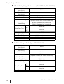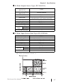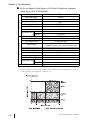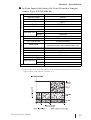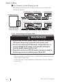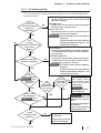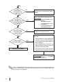
1
Flex Network User Manual Digital Electronics Corporation Preface Thank you for purchasing Pro-face's Flex Network units, hereafter referred to as the "Unit". The Unit is designed to be used with Pro-face's Graphic Logic Controller or Proface's LogiTouch Series units (hereafter referred to collectively as the "GLC") for distributed I/O connection. This manual explains the overall features and specifications of the Unit, as well as its installation procedures. Please be sure to read this manual thoroughly to understand the correct and safe usage of this product and its features. <Note> 1) It is forbidden to copy the contents of this manual, in whole or in part, except for the user's personal use, without the express permission of Digital Electronics Corporation of Japan. 2) The information provided in this manual is subject to change without notice. 3) This manual has been written with care and attention to detail; however, should you find any errors or omissions, please contact Digital Electronics Corporation and inform us of your findings. 4) Please be aware that Digital shall not be held liable by the user for any damages, losses, or third party claims arising from the uses of this product. All Company/Manufacturer names used in this manual are the registered trademarks of those companies. © 2001, Digital Electronics Corporation Flex Network® is a registered trademark of Digital Electronics Corporation in Japan and other countries. Flex Network User Manual 1 Preface Table of Contents Preface ........................................................................................................................ 1 Table of Contents ...................................................................................................... 2 Essential Safety Precautions ................................................................................... 4 General Precautions ................................................................................................. 6 Documentation Conventions................................................................................... 7 Flex Network Unit Models ...................................................................................... 7 Compatible GLC Units ............................................................................................ 8 UL/c-UL(CSA) Approval ........................................................................................ 9 CE Marking ............................................................................................................. 11 CHAPTER 1 INTRODUCTION 1.1 System Design ............................................................................................. 1-1 1.2 Flex Network Unit Types .......................................................................... 1-3 CHAPTER 2 SPECIFICATIONS 2.1 2.2 General Specifications ............................................................................... 2-1 2.1.1 Electrical ........................................................................................ 2-1 2.1.2 Environmental ................................................................................ 2-2 2.1.3 Structural ........................................................................................ 2-3 Performance Specifications ...................................................................... 2-4 2.2.1 Data Transfer Settings ................................................................... 2-4 2.2.2 Flex Network I/O Unit Input/Ouput ............................................. 2-4 2.3 Input/Output Circuit Drawings ............................................................. 2-10 2.4 Part Names and Features ........................................................................ 2-17 2.5 2.4.1 Flex Network I/F Unit ................................................................. 2-17 2.4.2 Flex Network I/O Unit ................................................................ 2-18 Dimensions ................................................................................................ 2-21 2.5.1 Flex Network I/F Unit ................................................................. 2-21 2.5.2 Flex Network I/O Unit ................................................................ 2-23 CHAPTER 3 INSTALLATION AND WIRING 3.1 2 Installation .................................................................................................. 3-1 3.1.1 Flex Network I/F Unit Installation ............................................... 3-1 3.1.2 I/O Unit Installation/Removal ...................................................... 3-2 3.1.3 Attaching a 32-Point I/O Unit ....................................................... 3-4 Flex Network User Manual Preface 3.2 Wiring .......................................................................................................... 3-5 3.2.1 Connecting the Flex Network Data Transfer Cable .................... 3-5 3.2.2 Connecting the Power Cord .......................................................... 3-8 3.2.3 Connecting the I/O Cable .............................................................. 3-9 3.2.4 General Cautions ......................................................................... 3-11 CHAPTER 4 PROBLEMS AND SOLUTIONS 4.1 Problem Solving ........................................................................................... 4-1 4.1.1 Prior to Troubleshooting ............................................................... 4-1 4.1.2 Error Code Display ........................................................................ 4-2 4.1.3 Troubleshooting ............................................................................. 4-3 INDEX Flex Network User Manual 3 Preface Essential Safety Precautions This guide contains a variety of safety markings for safe and correct operation of this Unit. Please read this installation guide and any related manuals carefully to fully understand how to correctly use this Unit's functions. Safety Symbols Please pay attention to these symbols and follow all instructions given. The safety symbols and their meanings are as follows: DANGER Indicates situations where severe bodily injury, death or major machine damage will definitely occur. WARNING Indicates situations where severe bodily injury, death or major machine damage can possibly occur. CAUTION Indicates situations where slight bodily injury or machine damage can occur. DANGERS • An emergency stop circuit and an interlock circuit should be constructed outside of this Unit. Constructing these circuits inside a system that uses this Unit may cause a runaway situation, system failure, or an accident due to unit failure. • Systems using this Unit should be designed so that output signals which could cause a serious accident are monitored from outside the Unit. • This Unit is designed to be a general-purpose device for general industries, and is neither designed nor produced to be used with equipment or systems in potentially lifethreatening conditions. If you are considering using this Unit for special uses, including nuclear power control devices, electric power devices, aerospace equipment, medical life support equipment, or transportation vehicles, please contact your local Pro-face distributor. 4 Flex Network User Manual Preface WARNINGS • Prior to installing, removing, wiring, and conducting maintenance or inspections, be sure to disconnect power to this Unit to prevent an electric shock or fire. • Do not disassemble or remodel this Unit, since it may lead to an electric shock or fire. • Do not use this Unit in an environment that contains flammable gases since an explosion may occur. • Do not use this Unit in an environment that is not specified in either the Installation Guide or User Manual. Otherwise, an electric shock, fire, malfunction or other failure may occur. • Due to the possibility of an electric shock or malfunction, do not touch this Unit's power terminals it is operating. CAUTIONS • Communication cables or I/O signal lines must be wired separately from the main circuit (high-voltage, large-current) line, high-frequency lines such as inverter and power lines. Otherwise, a malfunction may occur due to noise. • This Unit must be installed according to directions given in its Installation Guide and User manual. Improper installation may cause the Unit to malfunction or fail. • This Unit must be wired according to directions in the Installation Guide and User Manual. Improper wiring may cause a malfunction, failure or electric shock. • Do not allow foreign substances, including chips, wire pieces, water, or liquids to enter inside this Unit's case. Otherwise, a malfunction, failure, electric shock, or fire may occur. • When disposing of this Unit, it should be processed according to your country's industrial waste disposal laws. Flex Network User Manual 5 Preface General Precautions To Prevent Unit Damage • Avoid storing or operating this Unit in either direct sunlight or excessively dusty or dirty environments. • Because this Unit is a precision instrument, do not store or use it in locations where excessive shocks or vibration may occur. • Avoid covering this Unit's ventilation holes, or operating it in an environment that may cause it to overheat. • Avoid operating this Unit in locations where sudden temperature changes can cause condensation to form inside the Unit. • Do not use paint thinner or organic solvents to clean this Unit. 6 Flex Network User Manual Preface Documentation Conventions The list below describes the documentation conventions used in this manual. Symbol Meaning Indicates important information or procedures that must be followed for correct and risk-free software/device operation. *1 1) , 2) Indicates useful or important supplemental information. Indicates steps in a procedure. Be sure to perform these steps in the order given. Refers to useful or important supplemental information. Provides useful or important supplemental information. Pro-Control Indicates the Pro-Control Editor ladder logic development software. Editor Indicates a multi-link type connection is used. 1:N Generic name for the "GLC Series" of Graphic Logic Controllers made by Digital Electronic Corporation. In this manual, it also indicates GLC "LogiTouch" Series units". Flex Network Unit Models Flex Network Units allow the GLC to communicate via a Flex Network system. The available Flex Network Unit model numbers are shown below. System Name Unit Name Rating Memo Standard Unit UL/c-UL(CSA) Approved, GLC100-FN41 I/F Unit *1 CE Marked Unit FN-X16TS11 Standard Unit UL/c-UL(CSA) Approved, FN-X16TS41 CE Marked Unit FN-XY08T S11 Standard Unit UL/c-UL(CSA) Approved, FN-XY08T S41 8/16 Points CE Marked Unit Flex Network FN-Y08RL11 Standard Unit I/O Unit FN-Y08RL41 UL/c-UL(CSA) Approved, FN-Y16SK41 CE Marked Unit FN-Y16SC41 FN-Y32TS41 UL/c-UL(CSA) Approved, FN-XY16SK41 32 Points CE Marked Unit FN-XY16SC41 Flex Network Flex Network Unit Model No. GLC100-FN11 *1 The Flex Network I/F Unit (GLC100-FN11/GLC100-FN41) is compatible with all GLC100 Series and GLC300 Series units. It is not required for GLC2000 Series, or LogiTouch Series units. Flex Network User Manual 7 Preface Compatible GLC Units The following GLC units can be used with the Flex Network I/O and I/F units. General Name Series Name Unit Name Model No. GLC100L GLC100-LG41-24V GLC100S GLC100-SC41-24V GLC100 Series GLC300 Series GLC300S GLC300-TC41-24V GLC2300 Series GLC2000 GLC2400 Series Series *1 GLC2600 Series GLC2300L GLC2300T GLC2300-LG41-24V GLC2300-TC41-24V GLC2400T GLC2400-TC41-24V GLC2600T GLC2600-TC41-24V GLC LogiTouch Series *1 *2 Memo Requires Flex Network I/F Unit Requires Flex Network I/F Unit and Bus Conversion Unit LogiTouch Type-B GLC150-BG41-FLEX-24V LogiTouch Type-C GLC150-BG41-RSFL-24V *1 The 32 Point Flex Network I/O Unit (FN-X32TS41/FN-XY16SK41/FN-XY16SC41) is compatible with all GLC2000 Series and LogiTouch Series units. *2 The LogiTouch Type A* unit is not compatible with the Flex Network. 8 Flex Network User Manual Preface UL/c-UL(CSA) Approval Flex Network I/F Unit The GLC100-FN41 is a UL/c-UL(CSA) listed product. (UL file No.E182139) This unit conforms to the following standards: UL508 Industrial Control Equipment UL1604 For use with Electrical Equipment in Class I and II, Division 2 and Class III Hazardous (Classified) Locations in industrial control applications. CAN/CSA-C22.2, No. 1010-1 Safety requirements for electrical equipment for measurement and laboratory use. GLC100-FN41 (UL Registration Model: 2880063-01) <Cautions> • The GLC must be used as a built-in component of an end-use product. • This unit is designed to be attached to a GLC100 Series or GLC300 Series unit. • If the GLC is installed so as to cool itself naturally, be sure to install it in a vertical panel. Also, be sure that the GLC is mounted at least 100 mm away from any adjacent structures or equipment. If these requirements are not met, the heat generated by the GLC's internal components may cause the unit to fail to meet UL/c-UL standard requirements. UL1604 Conditions of Acceptability and Handling Cautions: 1. Power, input and output (I/O) wiring must be in accordance with Class I, Division 2 wiring methods - Article 501- 4(b) of the National Electrical Code, NFPA 70 within the United States, and in accordance with Section 18-152 of the Canadian Electrical Code for units installed within Canada. 2. Suitable for use in Class I, Division 2, Groups A, B, C and D, Hazardous Locations. 3. WARNING: Explosion hazard - substitution of components may impair suitability for Class I, Division 2. 4. WARNING: Explosion hazard - when in hazardous locations, turn power OFF before replacing or wiring modules. 5. WARNING: Explosion hazard - do not disconnect equipment unless power has been switched OFF, or the area is known to be non-hazardous. Flex Network User Manual 9 Preface Flex Network I/O Units The following Flex Network units are UL/c-UL (CSA) approved. • • • • • • • • FN-X16TS41 (UL File No. E 195835) FN-XY08TS41 (UL File No. E 195835) FN-Y08RL41 (UL File No. E 195835) FN-Y16SK41 (UL File No. E 195835) FN-Y16SC41 (UL File No. E 195835) FN-X32TS41 (UL File No. E 220851) FN-XY16SK41 (UL File No. E 220851) FN-XYL16SC41 (UL File No. E 220851) These Units conform to the following standards: UL508 Industrial Control Equipment CAN/CSA-C22.2, No. 1010-1 Safety requirements for electrical equipment for measurement and laboratory use. FN-X16TS41 (UL Registration Model: 2880063-02) FN-XY08TS41 (UL Registration Model: 2880063-03) FN-Y08RL41 (UL Registration Model: 2880063-04) FN-Y16SK41 (UL Registration Model: 2880063-05) FN-Y16SC41 (UL Registration Model: 2880063-06) FN-X32TS41 (UL Registration Model: 3080039-01) FN-XY16SK41 (UL Registration Model: 3080039-02) FN-XY16SC41 (UL Registration Model: 3080039-03) <Cautions> • This Unit must be used as a built-in component of an end-use product. • If this Unit is installed so as to cool itself naturally, be sure to install it on a vertical DIN rail or to a vertical panel via attachment holes. Also, be sure that this Unit is mounted at least 100 mm away from any adjacent structures or equipment. If these requirements are not met, the heat generated by this Unit's internal components may cause the Unit to fail to meet UL/c-UL standard requirements. • Any power supply device connected to the Unit should be a UL/c-UL(CSA) approved Class 2 power supply or Class 2 transformer. *1 Single unit power supplies, when connected to this Unit, multiple I/O units or when driving a load, should be designed so that the total power consumption of the I/O unit(s) and the total load current meets the standards for a Class 2 power supply, or a Class 2 power transformer. Also, be aware that the number of load producing points, and the load current value will determine the number of output points that can be simultaneously turned ON. *1 Class 2 power supplies and Class 2 transformers should not exceed an output of 30V, and at 8A or less, should not exceed 100V. 10 Flex Network User Manual Preface CE Marking Flex Network I/F Unit The GLC100-FN41 is a CE marked product that conforms to EMC directives EN55011 Class A and EN61000-6-2 (EN50082-2). <Cautions> Even though the GLC meets the abovementioned EMC standards, if it is installed into another piece of machinery, that machinery's installation, wiring or positioning method(s) used may cause the GLC to fail to meet the designated EMC standard. Therefore, the combination of the GLC and this machinery may need to be re-tested, as a final, complete unit. * For detailed CE marking information, please contact your local Pro-face distributor. Flex Network I/O Units The following Flex Network Units are CE marked products that conform to EMC directives EN55011 Class A and EN61000-6-2. [Compatible Units] FN-X16TS41, FN-Y16SC41, FN-XY08TS41, FN-Y08RL41, FN-Y16SK41, FN-X32TS41, FN-XY16SK41, FN-XY16SC41 * For detailed CE marking information, please contact your local Pro-face distributor. Flex Network User Manual 11 Preface Memo 12 Flex Network User Manual 1. System Design Chapter 1 2. Flex Network Unit Types Introduction This chapter explains the standard system design for the Flex Network unit, and the types of units available. 1.1 System Design The following information explains how to connect the GLC to a Flex Network I/F and I/O Unit. When connecting the I/O unit, 2 channels are available - CH1 and CH2. Each channel outputs the same data and either can be used for data transmission. The maximum number of connectable units, when using a single channel, is 31, and when using a second channel, the number increases by 32 to a total of 63. • The Flex Network uses high speed data transfer technology, and if a is cable used for data transfer that is not the same as that specified in this document, network data transfer performance cannot be guaranteed. Thus, be sure to use only the cable(s) recommended here. 3.2.1 Connecting the Flex Network Data Transfer Cable • When connecting the Flex Network I/F unit to a GLC 300 Series operator interface, the optional Bus Conversion unit is required. (Model No. GLC300-BCB41). • When turning the entire system's power ON, turn on the I/O unit's power supply before turning on the GLC's power. With One (1) Channel Flex Network I/F Unit *1 Flex Network I/O Unit GLC Maximum cable length: 200m (6Mbps) 100m (12Mbps) Maximum No. of Units: 31 *1 GLC2000 Series/LogiTouch Series do not require the Flex Network I/F Unit. Flex Network User Manual 1-1 Chapter 1 - Installation With Two (2) Channels Flex Network I/O Unit Flex Network I/F Unit CH1 GLC CH2 Maximum cable length: 400m (6Mbps), 200m (12Mbps) Maximum No. of units: 63 (31 + 32) When using two channels, up to 32 nodes can be connected to either channel. Standard System Design 16 Input Points 8 points - relay output to next station *1 Sensor DC24V GLC Operation Switch DC24V 8 points Input/ 8 points Output 32 Input points Valve Actuator DC24V Sensor Lamp Operation Sensor Switch to next station *1 Operation Switch DC24V 6Mbps is the recommended speed. *1 Be sure the Terminal Switch (TERM) of the network's last unit (at each end) is turned ON. 2.4.2 Flex Network I/O Unit 1-2 Flex Network User Manual Chapter 1 - Installation 1.2 Flex Network Unit Types The following tables explain the different types of Flex Network units. These are optional GLC units and are sold separately. Expansion Units I/F Unit Item Flex Network I/F Unit Model No. Description Attached to rear of GLC100 or GLC300 series units to allow data transfer over a Flex Network. Not required for GLC100-FN11 GLC2000 Series /LogiTouch Series units. GLC100-FN41 GLC300 Series units require the separately sold Bus Conversion Unit. I/O Units Item Flex Network 16-point Input Sink-Source type I/O Unit Flex Network 8-pt Input SinkSource / 8-pt Transistor Output Sink type I/O Unit Flex Network 8-pt Relay Output / 1 Common type I/O Unit Flex Network 16-point Output Sink type I/O Unit Flex Network 16-pt Output Source type I/O Unit Flex Network 32-point Input Sink-Source type I/O Unit Flex Network 16-pt Input SinkSource /16-pt Transistor Output Sink type I/O Unit Flex Network 16-pt Input SinkSource/16-pt Transistor Output Source type I/O Unit Flex Network User Manual Model No. Description FN-X16TS11 FN-X16TS41 16-point sink-source type shared I/O Unit. Sink-source can be selected by wiring between the input circuit and common (COM terminal) cabling. FN-XY08TS11 FN-XY08TS41 I/O Unit with combination of 8-pt sink-source inputs and 8-pt transistor sink outputs. Can be connected to DC24V, 200mA electromagnetic bulb, or pilot lamp for output. FN-Y08RL11 FN-Y08RL41 8-point relay output / 1 common type I/O unit. Can be connected to AC240V (1A load). FN-Y16SK41 16-point sink output I/O unit FN-Y16SC41 16-point source output I/O unit. FN-X32TS41 32-point sink-source type shared I/O Unit. Sink-source can be selected by wiring between the input circuit and common (COM terminal) cabling. I/O Unit with combination of 16-pt sink-source inputs and 16-pt FN-XY16SK41 transistor sink outputs. Can be connected to DC24V, 200mA electromagnetic bulb, or pilot lamp for output. I/O Unit with combination of 16-pt sink-source inputs and 16-pt FN-XY16SC41 transistor source outputs. Can be connected to DC24V, 200mA electromagnetic bulb, or pilot lamp for output. 1-3 Analog Unit Item Model No. Flex Network 4Channel Analog/ FN-AD04AH11 Digital Conversion Input Unit Flex Network 4Channel Analog/ FN-DA04AH11 Digital Conversion Output Unit Description Stores analog signal in this unit after converting it to 12-bit digital signal. Converts 12-bit digital signal to analog signal and sends output. Single Axis Positioning Unit Item Flex Network Single-Axis Positioning Unit Model No. FN-PC10SK41 Description Controls a servo motor and stepping motor. Handles up to 2MHz. High-Speed Counter Unit Item Flex Network High-Speed Counter Unit Model No. FN-HC10SK41 Description Maximum speed is 200Kpps. Can be used in combination with positioning units and work rate counters to perform cutting applications, due to the simultaneous output and programmable cam switch features. Optional Expansion Unit Item Bus Conversion Unit Model No. Description This unit is attached to the rear of the GLC300 Series. It must be attached before the Flex Network I/F GLC300-BCB41 (GLC100-FN11/ GLC100-FN41) unit is attached to the GLC300 Series unit. Optional Items Ite m Single -Ax is Te a ching Loa de r Mode l No. FN-PC10LD41 Single -Ax is Motor FN-PC10CB01 Drive r Conne ction (1m) Ca ble Fle x Ne tw ork Com m unica tion Ca ble De scription Program -input unit for the Flex Network single-axis positioning unit. Used for parameter entry, as well as positioning check and m ovem ent.(includes one piece of FN-LD10CBL.) Connects the Flex Network single-axis positioning unit and the servo and stepping drivers. FN-CABLE 201031-M S (10m ) FN-CABLE 2050Connects distributed Flex Network units. 31-M S (50m ) FN-CABLE 220031-M S (200m ) Maintenance Items Item Single-Axis Teaching Loader Cable Flex Network User Manual Model No. FN-LD10CBL (5m) Description Connects the Flex Network single-axis positioning unit and the single-axis teaching loader. 1-4 1. 2. 3. 4. 5. General Specifications Functional Specifications I/O Circuit Connection Drawings Part Names and Features Dimensions Chapter 2 Specifications The Flex Network I/F Unit (GLC100-FN11/GLC100-FN41) is compatible with all GLC100 Series and GLC300 Series units. It is not required for GLC2000 Series/ LogiTouch Series Units. GLC2000 Series User Manual/LogiTouch Series User Manual 2.1 General Specifications 2.1.1 Electrical Flex Network I/F Unit Rated Voltage Power Consumption Voltage Endurance Insulation Resistance DC5V +/-5% (supplied from GLC) 1.25W or less AC1500V 10mA for 1min. (between external charging and FG terminals) DC500V at 10M Ω or higher (between external charging and FG terminals) Flex Network I/O Unit (Control Section) FN-X16TS11/ FN-X16TS41 FN-XY08TS11/FN-XY08TS41 FN-Y16SK41/ FN-Y16SC41 Rated Voltage Rated Voltage Range Allowable Voltage Interrupution Power Consumption Voltage Endurace Insulation Resistance In-rush Current Flex Network User Manual FN-X32TS41 FN-XY16SK41 FN-XY16SC41 FN-Y08RL11 FN-Y08RL41 DC24V DC20.4V to DC28.8V 10ms or less (Power Supply: DC24V) 1.5W or less 1W or less AC1500V 10mA for 1min. (between power/Input and Output, and FG terminals) 2.5W or less AC500V 10mA for 1 min. (between power/ Input and Output, and FG terminals) DC500V at 10M Ω or higher (between power/Input and Output, and FG terminals) 30A or less 2-1 Chapter 2 - Specifications 2.1.2 Environmental Flex Network I/F Unit Operating Temperature 0oC to 50oC (cannot be higher than GLC unit) Storage Temperature Operating Humidity Storage Humidity -20oC to +60oC 20%RH to 85%RH (non-condensing) 20%RH to 85%RH (non-condensing) Air Purity (Dust) 0.1mg/m 3 or less (non-conductive levels) Free of corrosive gasses Corrosive Gasses Vibration Endurance Noise Immunity (via noise simulator) Electrostatic Discharge Immunity 10Hz to 25Hz 19.6m/s2 (in X,Y,Z directions for 30min. each) Noise Duration: 1000Vp-p Pulse Duration: 1µs Rise Time: 1ns GLC100-FN11: 4kV (contact discharge) GLC100-FN41: 6kV (IEC61000-4-2, RH-1/ESD-3) Flex Network I/O Unit FN-X16TS11/FN-X16TS41 FN-XY08TS11/FN-XY08TS41 FN-Y16SK41 FN-Y16SC41 FN-Y08RL11/FN-Y08RL41 Operating Temperature Storage Temperature Operating Humidity Storage Humidity Air Purity (Dust) Corrosive Gasses o o 0 C to 55 C o o -25 C to +70 C 5%RH to 95%RH (non-condensing) (wet bulb temperature: less than 39°C) 5%RH to 95%RH (non-condensing) (wet bulb temperature: less than 39°C) 3 0.1mg/m or less (non-conductive levels) Free of corrosive gasses 5Hz to 55Hz Vibration Endurance FN-X32TS41 FN-XY16SK41 FN-XY16SC41 2 60m/s (in X,Y,Z directions for 2 hours each) IEC61131-2 (JIS B 3501) compliant When vibration IS NOT continuous: 10Hz to 57Hz 0.075mm, 2 57Hz to 150Hz 9.8m/s When vibration IS continuous: 10Hz to 57Hz 0.035mm, 2 Shock Endurance Noise Immunity (via noise simulator) Electrostatic Discharge Immunity 2-2 2 57Hz to 150Hz 4.9m/s X,Y,Z directions for 10 times (80 min.) IEC61131-2 (JIS B 3501) compliant 300m/s (for 10ms in X,Y, Z directions 2 147 m/s (for 11ms in X, Y, Z directions 3 times each) - 2 times each) Noise Voltage: 1000Vp-p, Pulse Duration: 1µs, Rise Time: 1ns 6kV (IEC61000-4-2, RH-1/ESD-3) Flex Network User Manual Chapter 2 - Specifications 2.1.3 Structural Flex Network I/F Unit Cooling Method Weight External Dimensions Natural air circulation 350g or less W 111mm [4.37in.] x H 120mm [4.72in.] x D 31.5mm [1.24in.] (Main unit only, not including connector) Flex Network I/O Unit Attachment Method Cooling Method Weight External Dimensions Rating Flex Network User Manual FN-X16TS11/FN-X16TS41 FN-X32TS41 FN-XY08TS11/FN-XY08TS41 FN-XY16SK41 FN-Y16SK41 FN-XY16SC41 FN-Y16SC41 FN-Y08RL11/FN-Y08RL41 via 35mm DIN rail or by attachment screws Natural air circulation 150g or less 350g or less W 108mm [4.25in.] x H 45mm W 110mm [4.33in.] x H 95mm [1.77in.] x D 49mm [1.93in.] [3.74in.] x D 57mm [2.24in.] IP20 2-3 Chapter 2 - Specifications 2.2 Performance Specifications 2.2.1 Data Transfer Settings Communication T ype Connection Method T ransfer Distance T ransfer Method T ransfer Speed T ransfer I/F Error Check No. of Stations 1:N Multi Drop At 6Mbps 200m per CH, at 12Mbps100m per CH During cyclic period, distributed transmission, Half-duplex 6Mbps, 12Mbps Differential method, Pulse transfer resistance Format check, bit check, CRC-12 check 63 (max.), 1008 I/O points 2.2.2 Flex Network I/O Unit Input/Ouput 16 Point Input Sink/Source type (FN-X16TS11, FN-X16TS41) Rated Input Voltage Max. Input Voltage No. of Input Points DC24V DC28.8V 16 points (sink/source type - dual use) Input Type Type 1 DC15V or higher DC5V or less 4.1kΩ 1.5ms or less 1.5ms or less 1 Input ON Voltage Input OFF Voltage Input Impedance OFF-ON Input Delay ON-OFF No. of Exclusive Use Nodes *1 *1 Digital input is for detecting signals from mechanical switching devices such as relay contacts, push buttons, switches, etc. 2-4 Flex Network User Manual Chapter 2 - Specifications 8 Point Input Sink-Source /8 Point Transistor Output Source Type (FN-XY08TS11, FN-XY08TS41) I N P U T O U T P U T Rated Input Voltage Max. Input Voltage No. of Input Points DC24V DC28.8V 8 points (sink/source type - dual use) Input T ype Type 1 DC15V or higher DC5V or less 4.1kΩ 1.5ms or less 1.5ms or less DC24V DC20.4V to DC28.8V 8 points (Open drain sink output) 0.2A or less None DC1.5V or less DC39V +/-1V 0.1mA or less 1ms or less 1ms or less 1 Input ON Voltage Input OFF Voltage Input Impedance OFF-ON Input Delay ON-OFF Rated Output Voltage Rated Output Voltage Range No. of Output Points Output Current Short Circuit Protection Voltage Drop (ON Voltage) Clamp Voltage Current Leakage OFF-ON Output Delay T ime ON-OFF No. of Exclusive Use Nodes *1 *1 Digital input is for detecting signals from mechanical switching devices such as relay contacts, push buttons, switches, etc. Flex Network User Manual 2-5 Chapter 2 - Specifications 8 Point Relay Output/1 Common (FN-Y08RL11, FN-Y08RL41) Rated Output Voltage (from V+ to V-) DC24V Rated Output Voltage Range (from V+ to V-) DC20.4V to DC28.8V Power Consumption No. of Output Points Maximum Load Voltage Contact Rating OFFON Output Delay T ime ONOFF Max. Open/Close Load Initial Shorting Resistance Electrical Life Mechanical Life No. of Exclusive Use Nodes 1.2W or less (when all outputs are ON /DC24V) 8 points/1 common 1.0A/1 point (8 points/1 common - Max. common current 4.0A) AC240V, 1A (resistance load, induced load) DC24V, 1A (resistance load, induced load) 10ms or less 5ms or less 1mA/DC5V 50m Ω or less 100,000 operations or more 20 million operations or more 1 16 Point Output Sink Type (FN-Y16SK41) Rated Output Voltage (from V+ to V-) Rated Output Voltage Range (from V+ to V-) No. of Output Points Output Current Short Circuit Protection Voltage Drop (ON Voltage) Clamp Voltage Current Leakage OFFON Output Delay T ime ONOFF No. of Exclusive Use Nodes 2-6 DC24V DC20.4V to DC28.8V 16 points 0.2A/point (16 points/1 common, max. common current 2.0A) None DC1.5V or less DC39V +/-1V 0.1mA 1ms or less 1ms or less 1 Flex Network User Manual Chapter 2 - Specifications 16 Point Output Source Type (FN-Y16SC41) Rated Output Voltage (from V+ to V-) Rated Output Voltage Range (from V+ to V-) No. of Output Points Output Current Short Circuit Protection Voltage Drop (ON Voltage) Clamp Voltage Current Leakage Output Delay OFF-ON Time ON-OFF No. of Exclusive Use Nodes DC24V DC20.4V to DC28.8V 16 points 0.2A/point (16 points/common, max. common current 2.0A) None DC1.5V or less DC39V +/-1V 0.1mA 1ms or less 1ms or less 1 32 Point Input Source/Sink Type (FN-X32TS41) Rated Input Voltage Max. Input Voltage No. of Input Points DC24V DC28.8V 32 points (sink/source type - dual use) Input T ype Type 1 DC15V or higher DC5V or less 4.2kΩ 1.5ms or less 1.5ms or less 2 Input ON Voltage Input OFF Voltage Input Impedance OFF-ON Input Delay ON-OFF No. of Exclusive Use Nodes *1 *1 Digital input is for detecting signals from mechanical switching devices such as relay contacts, push buttons, switches, etc. Flex Network User Manual 2-7 Chapter 2 - Specifications 16 Point Input Sink-Source/16 Point Transistor Output Sink Type (FN-XY16SK41) I N P U T O U T P U T Rated Input Voltage Max. Input Voltage No. of Input Points DC24V DC28.8V 16 points (sink/source type-dual use) Input Type Type 1 DC15V or higher DC5V or less 4.2kΩ 1.5ms or less 1.5ms or less DC24V DC20.4V to DC28.8V 16 points (sink type) 0.2A/1 point (16 points/1 common, max. common current: 1.6A) None 3.5A, DC125V built-in Chip Fuse (cannot be replaced) DC1.5V or less DC39V +/-1V 0.1mA or less 1ms or less 1ms or less 1 Input ON Voltage Input OFF Voltage Input Impedance OFF-ON Input Delay Time ON-OFF Rated Output Voltage Rated Output Voltage Range No. of Output Points Output Current Output Protection Built-in Fuse Voltage Drop (ON Voltage) Clamp Voltage Current Leakage OFF-ON Output Delay Time ON-OFF No. of Exclusive Use Nodes *1 *1 Digital input is for detecting signals from mechanical switching devices such as relay contacts, push buttons, switches, etc. 2-8 Flex Network User Manual Chapter 2 - Specifications 16 Point Input Sink-Source/16 Point Transistor Output Source Type (FN-XY16SC41) I N P U T O U T P U T Rated Input Voltage Max. Input Voltage No. of Input Points DC24V DC28.8V 16 points (sink/source type-dual use) Input T ype Type 1 DC15V or higher DC5V or less 4.2kΩ 1.5ms or less 1.5ms or less DC24V DC20.4V to DC28.8V 16 points (source type) 0.2A/1 point (16 points/1 common, max. common current: 1.6A) None 3.5A, DC125V built-in Chip Fuse (cannot be replaced) DC1.5V or less DC39V +/-1V 0.1mA or less 1ms or less 1ms or less 1 Input ON Voltage Input OFF Voltage Input Impedance OFF-ON Input Delay Time ON-OFF Rated Output Voltage Rated Output Voltage Range No. of Output Points Output Current Output Protection Built-in Fuse Voltage Drop (ON Voltage) Clamp Voltage Current Leakage OFF-ON Output Delay T ime ON-OFF No. of Exclusive Use Nodes *1 *1 Digital input is for detecting signals from mechanical switching devices such as relay contacts, push buttons, switches, etc. Flex Network User Manual 2-9 Chapter 2 - Specifications 2.3 Input/Output Circuit Drawings This section explains the Flex Network I/O unit circuit connection drawings. If the I/O unit's power and output lines, and the sensor power lines seem to be receiving excessive levels of field noise, be sure to separate the power and signal lines. 16 Point Input Sink/Source Type (FN-X16TS11, FN-X16TS41) This drawing shows the connection between the input section and the sink output type. *1 Input 0 INPUT Internal Circuit Input 15 *1 Dotted line shows the source output connection. 2-10 Flex Network User Manual Chapter 2 - Specifications 8 Point Input Sink-Source/8 Point Transistor Output Sink Type (FN-XY08TS11, FX-XY08TS41) This drawing shows the connection between the input section and the sink output type. *1 Dotted line shows the source output connection. Flex Network User Manual 2-11 Chapter 2 - Specifications 8 Point Relay Output/1 Point Common (FN-Y08RL11, FN-Y08RL41) The relay specifications can change the COM power supply. Output 0 Internal Circuit Output 7 2-12 Flex Network User Manual Chapter 2 - Specifications 16 Point Output Sink Type (FN-Y16SK41) Output 0 Internal Circuit Output 15 16 Point Output Source Type (FN-Y16SC41) Output 0 Internal Circuit Output 15 Flex Network User Manual 2-13 Chapter 2 - Specifications 32 Point Input Sink/Source Type (FN-X32TS41) This drawing shows the connection between the input section and the sink output type. *1 Dotted line shows the source output connection. *2 When IN0 to IN15 are used, use COM1. When IN16 to IN31 are used, use COM2 as the input common. 2-14 Flex Network User Manual Chapter 2 - Specifications 16 Point Input Sink-Source/16 Point Transistor Output Sink Type (FN-XY16SK41) This drawing shows the connection between the input section and the sink output type. *1 Dotted line shows the source output connection. Flex Network User Manual 2-15 Chapter 2 - Specifications 16 Point Input Sink-Source/16 Point Transistor Output Source Type (FN-XY16SC41) This drawing shows the connection between the input section and the source output type. *1 Dotted line shows the sink output connection. 2-16 Flex Network User Manual Chapter 2 - Specifications 2.4 Part Names and Features The Flex Network I/F Unit (GLC100-FN11/GLC100-FN41) is compatible with all GLC100 Series and GLC300 Series units. It is not required for GLC2000 Series/ LogiTouch Series Units. GLC2000 Series User Manual/LogiTouch Series User Manual 2.4.1 Flex Network I/F Unit A: GLC Connector Connects to GLC Expansion Unit connector. A B: Flex Network I/F Unit Connector Flex Network I/O unit connects here to provide Flex Network communication connector. 6 5 4 3 2 1 B Pin No. 6 5 4 3 2 1 Signal Name CH2 Shield Line (SLD) CH2 Data Transmit (TR-) CH2 Data Transmit (TR+) CH1 Shield Line (SLD) CH1 Data Transmit (TR-) CH1 Data Transmit (TR+) C: Status LED Indicates the status of the unit. C Flex Network User Manual Status LED POW (Green LED) RUN (Green LED) ERR (RED LED) Condition When power is supplied Blinks when data transfer is enabled. Blinks when the unit is malfunctioning. 2-17 Chapter 2 - Specifications 2.4.2 Flex Network I/O Unit A B D A: Dip Switches Sets the output hold settings, transmission speed and station no. (upper 1st digit). C E (FN-X16TS41 unit) B: Rotary Switch Uses the lower 1st digit to set the station no. 8/16 point 32 point C: Terminator Turns the termination resistance feature ON or OFF. D C A B E (FN-X32TS41 unit) D: Status LED Indicates the following conditions. Status LED PWR (Green LED) ERR (RED LED) 0 - 15 (ORANGE LED) Condition When unit is first turned ON. Lights when the unit is malfunctioning. Lights when each I/O point turns ON. E: DIN Rail Attachment Hook Use to attach the I/O Unit to the DIN rail. Output Hold Settings The left-most dip switch is used to turn this setting ON/OFF. The factory setting is OFF (No Hold) Output Hold OFF Dip Switch 1 Output Hold ON Output Hold ON (Hold) When a communication error occurs, the unit will HOLD the output condition received in the previous communication cycle. When the next cycle is performed and the next command is successfully received, the output will then be changed. 2-18 Flex Network User Manual Chapter 2 - Specifications Output Hold OFF (Non-Hold) When a communication error occurs, all outputs are reset to 0 (OFF). When normal communication is restored, the output is also restored. • When output hold is used, the output ON signal is held when an error occurs. As a result, be sure to structure your system so that a V+ terminal does not control an emergency safety circuit. This type of feature is usually referred to as a fail-safe system. 3.2.3 Connecting the I/O Cable (With 2 transistor units) • When the Logic Program changes from the RUN condition to either the OFFLINE mode or RESET, The GLC or the I/O signal will be performed as shown below, regardless of the Output Hold Setting. Be sure to consider this when changing to either the OFFLINE or RESET modes. GLC Condition ON I/O Signal OFF RUN OFFLINE RUN Output from Logic Program OFF Output from Logic Program Please remember that the Reset mode's I/O signal OFF timing is not fixed. Communication Speed Settings The Dip Switch that is the second from the left controls the communication speed (6Mbps or 12Mbps). The factory setting is 6Mbps and is recommended. 6Mbps 12Mbps The Communication Speed setting status is read when the FN-HC unit is turned ON. To change this setting, turn the FN-HC unit OFF, change the setting and then turn the unit ON again. S-No. (Station Number) Setting Station numbers from 1 to 63 are set in hexadecimal (01h to 3Fh) The factory setting is 0. The hex upper digit is controlled by the two dip switches on the right side, via ON/OFF settings. ON OFF indicates the hex upper digit Flex Network User Manual 2-19 Chapter 2 - Specifications The arrow's tip indicates the position 8/16 point 32 point S-No. Setting Example S-No. Dip Switch Base 10 S-No. 1 (01h) the 2nd from the right right side Rotary Switch OFF (0) OFF (0) 1 or OFF (0) ON (1) S-No. 16 (10h) S-No. 63 (3Fh) 0 or ON (1) ON (1) F or The S-No. setting status is read when the FN-HC unit is turned ON. To change this setting, turn the FN-HC unit OFF, change the setting and then turn the unit ON again. Termination Settings This setting helps prevent reflections (echoes) from the terminating unit. (adjusts the termination impedance) Be sure that each channel in your system's final unit has this termination setting set to ON. OFF ON The Termination Resistance setting status is read when the FN-HC unit is turned ON. To change this setting, turn the FN-HC unit OFF, change the setting and then turn the unit ON again. 2-20 Flex Network User Manual Chapter 2 - Specifications 2.5 Dimensions 2.5.1 Flex Network I/F Unit 31.5 [1.24] Units: mm [in.] 120 [4.72] 111 [4.37] Flex Network User Manual 2-21 Chapter 2 - Specifications Flex Network I/F Unit when attached to a GLC 100 Units: mm [in.] (42) ([1.65]) 111 [4.37] 155.5 [6.12] (88) ([3.46]) 123 (4.84) 31.5 [1.24] (56.5) ([2.22]) Flex Network I/F Unit when attached to a GLC 300 Units: mm [in.] When the Flex Network Unit is attached to a GLC 300 Series unit, the optional Bus Conversion Unit is required. (90) ([3.54]) 227 [8.94] 301 [11.85] 2-22 (122) ([4.80]) 31.5[1.24] 120 [4.72] 111 [4.37] (24) ([0.94]) Bus Conversion unit is shown as Flex Network User Manual . Chapter 2 - Specifications 2.5.2 Flex Network I/O Unit All I/O units share the same dimensions. Units shown here are 8/16 Point and 32 Point types. Units: mm [in.] 8/16 Point Unit 3.9 [0.15] 33 [1.30] 45 [1.77] 18.9[0.74] 22.5[0.89] 12.1 [0.48] 3.5 [0.14] 49[1.93] 15.1[0.59] 28.2[1.11] 108 [4.25] (FN-X16TS41 unit) 32 Point Unit Units: mm [in.] 32 Point Unit Only 15.5 [0.61] DIN rail center =I/O unit center 5[0.20] 33.2[1.31] 33.2[1.31] 95[3.74] 110[4.33] 20.5[0.81] 39[1.54] 57[2.24] 3.3 [0.13] Flex Network User Manual (FN-X32TS41 unit) 2-23 Chapter 2 - Specifications 32 Point unit when attached to a GLC2300 Series unit The following diagrams show the I/O unit attached to a DIN rail (recommended length: 105mm), which is attached to the rear of the GLC. This type of installation is only for GLC 2300 Series units. 115[4.53]*1 95[3.74] 4[0.16] 110 [4.33] *1 This depth dimension (115mm) includes a DIN rail. (H35mm x D7mm) 2-24 Flex Network User Manual 1. Installation 2. Wiring Chapter 3 Installation and Wiring The Flex Network I/F Unit (GLC100-FN11/GLC100-FN41) is compatible with all GLC100 Series and GLC300 Series units. It is not required for GLC2000 Series/ LogiTouch Series Units. GLC2000 Series User Manual/LogiTouch Series User Manual 3.1 Installation WARNING Prior to installing the Flex Network Unit: Be sure that the main power supply is turned completely OFF before beginning to wire the unit. 3.1.1 Flex Network I/F Unit Installation Be sure to read the User Manual for you GLC unit prior to installing this expansion unit. 1) Be sure the GLC's main power supply is turned OFF. Seal 2) Peel the GLC 100's rear face connector seal off to expose the connector. Be sure the GLC unit's power cord terminals are attached to the GLC before installing the Flex Network I/F unit. This is because the power terminals cannot be connected after the Flex Network unit is attached. GLC100 Series unit GLC Unit User Manual Flex Network User Manual 3-1 Chapter 3 - Wiring 3) Attach the Flex Network unit and secure it in place with its three (3) attachment screws. Flex Network I/F Unit • The torque required for these screws on only 0.5 to 0.6n•m2 • When attaching this unit to the GLC-300, a Bus Conversion adapter (GLC300BCB41) is required. For this unit's installation method, refer to its Installation Guide. 3.1.2 I/O Unit Installation/Removal Attaching the Unit to a 35 mm DIN Rail Attachment Place the unit's curved, top lip over the top of the DIN rail, and then tilt the unit down until the bottom face attachment clip clicks into place. DIN Rail DIN Rail I/O unit (8/16 Points) I/O unit (32 Points) • Be sure to confirm the unit's top and bottom faces before installing the unit. • The unit’s attachment clip can be set to remain open. When attaching the unit, be sure to close the attachment clip completely and confirm that the I/O unit is set securely on the DIN rail. Removal Use a standard screwdriver to force the unit's attachment clip down until the bottom of the unit is freed from the rail. Next, tilt the unit up and remove. DIN Rail I/O unit (8/16 Points) Standard Screwdriver 3-2 DIN Rail I/O unit (32 Points) Down Standard Screwdriver Down Flex Network User Manual Chapter 3 - Wiring When Installing the Unit in a Panel Drill installation holes in the panel according to the dimensions given below and use M4 screws to attach the unit. A torque of only 0.5 to 0.6N•m is sufficient. Unit: mm [in.] (2 2-φ φ4.5 0.1 8) DIN rail center line 48.1 to 50.3 [1.89 to 1.98] 50.3 [1.98] (35.0 [1.38]) I/O unit center line I/O unit outline 18.9 [0.74] 16.1 [0.63] 8/16 Point Unit (98.4 to 100.6 [3.87 to 3.96]) 32 Point Unit 42.5 [1.67] 85.0 [3.35] I/O unit center line I/O unit outline 2φ− φ−4.2 φ− φ0.17] [2-φ DIN rail center line 50.0 [1.97] 100.0 [3.94] Flex Network User Manual 3-3 Chapter 3 - Wiring 3.1.3 Attaching a 32-Point I/O Unit This explanation attaches a 32-Point I/O Unit to a DIN rail, then to the rear of the GLC. This installation method can only be used with a GLC2300 Series unit. 1) Attach the DIN rail (H35mm, recommended length: 105mm) to the rear of the GLC2300. Fasten the two (2) M4 screws as shown. (The length is less than 6mm.) The torque required for these screws is only 0.5 to 0.6 N•m2. 2) Attach the I/O Unit (32-Point unit) to the DIN rail. 3.1.2 I/O Unit Installation/Removal Attaching the Unit to a 35mm DIN Rail 32-Point I/O Unit 3-4 GLC2300 Flex Network User Manual Chapter 3 - Wiring 3.2 Wiring WARNING Prior to wiring the Flex Network Unit: Be sure that the main power supply is turned completely OFF before beginning to wire the Unit. 3.2.1 Connecting the Flex Network Data Transfer Cable Use jumper wiring between the Flex Network I/F and I/O units, as well as between each distributed I/O unit (T-type connections are not possible) We suggest the following cables for your Flex Network. Retailer Digital Electronics Corporation Model No. Length FN-CABLE2010-31-MS 10m FN-CABLE2050-31-MS 50m FN-CABLE2200-31-MS 200m Flex Network I/O Unit Wiring The cable should be made as shown below: Blue(TR+) White(TR-) Shield(SLD) The shield line should either be taped or be covered with a plastic tube. Use the following type of crimp terminals. 6.0[0.24] or less 3.8[0.15] or less 5.2[0.20] or more Unit: mm[in.] φ 3.2[φ φ 0.13] or larger Crimp terminals should either be taped or be covered with a plastic tube. • The required torque for securing ring terminals is 0.3 N•m2 • Up to 2 ring terminals can be attached to a single terminal screw. Flex Network User Manual 3-5 Chapter 3 - Wiring Flex Network I/F Unit Wiring Remove the wire's external covering and insert the wire center strand into the opening. Unit: mm[in.] Blue(TR+) 6 to 8[0.24 to 0.31] * Do not solder end White(TR-) Shield (SLD) (25 to 35 [0.98 to 1.38]) • Be sure to tape or put a plastic tube over the shield line. • Do not solder the wire itself. This could lead to a bad or poor contact. Connecting the Flex Network Cable to the Flex Network I/F Unit Flex Network I/F Unit Flex Network I/F Connector 56 34 2 1 Terminal screws D R- SL R+ T LD T S R T TR+ Flex Network Communication connector (included with Flex Network I/F unit) Set screw Flex Network Communication cable CH1 CH2 3-6 Pin No. Insulation Color 1 Blue 2 White 3 Shield 4 Blue 5 White 6 shield Meaning CH1 Comm. Data (TR+) CH1Comm Data (TR-) CH1 Shield (SLD) CH2 Comm. Data (TR+) CH2 Comm Data (TR-) CH2 Shield (SLD) Flex Network User Manual Chapter 3 - Wiring Connecting the Flex Network Cable to a GLC2400/GLC2600 Series Unit Screwlock Terminal Block Pin No. 1 2 3 4 5 6 7 8 9 10 11 12 Signal AUXCOM AUXRESET TR+ TR SLD TR+ TR SLD RESERVE SP OUT GND LINE OUT Meaning External Reset Common External Reset Input CH1 Communication Data CH1 Communication Data CH1 Cable/Shielded Line CH2 Communication Data CH2 Communication Data CH2 Cable/Shielded Line Reserve Speaker Output Ground Sound Output External Reset Flex Network Communication Sound Output For more information about the GLC2400/GLC2600 Series unit, see the "GLC2000 Series User Manual" Connecting the Flex Network Cable to a GLC2300/LogiTouch Series Unit Screwlock Terminal Block Pin No. 1 2 3 4 5 6 Signal TR+ TR SLD TR+ TR SLD Meaning CH1 Communication Data CH1 Communication Data CH1 Cable/Shielded Line CH2 Communication Data CH2 Communication Data CH2 Cable/Shielded Line For more information about the GLC2300/LogiTouch Series unit, see each series unit's "User Manual" • Use a small sized screwdriver to tighten the set screws. • Use both attachment screws to attach the connector to the I/F unit. (recommended torque is 0.22 to 0.25N•m) • If the central wire's end (individual) wires are not twisted correctly, the end wires may either short against each other, or against an electrode. When using pin terminals, the following maker is recommended. Phoenix Connector: AI0.5-6WH AI0.3-6TQ Flex Network User Manual 3-7 Chapter 3 - Wiring Flex Network System Wiring Layout The following drawing shows the wiring layout used for wires from the Flex Network I/F connector. FN-X16TS41(S-No.1) FN-SY08TS41(S-No.2) FN-Y08RL41(S-No.31) Flex Network I/F unit CH1 FN-Y08RL41(S-No.32) FN-SY08TS41(S-No.33) FN-X16TS41(S-No.63) Flex Network Comm. Connector CH2 3.2.2 Connecting the Power Cord WARNINGS • Be sure that the main power supply is turned completely OFF before beginning to wire the unit's power cord. • The I/O unit uses only DC24V power. Using either the incorrect voltage or AC power could result in damage to both the power supply and the unit. • Since this unit has no OFF/ON switch, be sure to install a breaker type device to switch power ON or OFF. • Wherever possible, use thick lines (max. 1.25mm2(0.05in2) and be sure to twist the wire ends to reduce noise. • Use the same type of crimp terminals as used for the Flex Network Communication Cable. 3-8 Flex Network User Manual Chapter 3 - Wiring 3.2.3 Connecting the I/O Cable • Be sure to use a cable that is 0.75 to 1.25mm2(0.03 to 0.05in2) thick. • Use the same type of crimp terminals as used for the Flex Network Communication Cable. • Check that all I/O Unit terminal screws are securely tightened, even if they are not used. • Do not allow the wire pieces to fall inside the unit. Input Wiring When two (2) DC input units (FN-X16TS11/FN-X16TS41/FN-X32TS41) are used, with the same common line, use the following wiring setup. For Sink Output type: FN-X16TS41 FN-X16TS41 When using a source ouput type, change the input circuit and the common (COM) lines. Output Wiring When using a Relay Output unit (FN-Y08RL11/FN-Y08RL41) together with noise generating magnetic devices or valves, attaching a diode for DC power, and a surge absorber for AC power is recommended FN-Y08RL41 FN-Y08RL41 Flex Network User Manual 3-9 When using the Transistor output unit, (FN-XY08TS11/FN-XY08TS41/FNY16SC41/FN-Y16SK41/FN-XY16SK41/FN-XY16SC41), be sure to connect a Reverse Start Power Absorbing Diode to both ends of the load. FN-XY08TS41 When using the Transistor output unit, (FN-XY08TS11/FN-XY08TS41/FNY16SC41/FN-Y16SK41/FN-XY16SK41/FN-XY16SC41), be sure to connect a Reverse Start Power Absorbing Diode to both ends of the load. FN-XY08TS41 When attaching two (2) Transistor Ouput units (FN-XY08TS11/FN-XY08TS41/ FN-Y16SC41/FN-Y16SK41/FN-XY16SK41/FN-XY16SC41) with the same Common line, be sure to use the wiring shown below. FN-XY08TS41 FN-XY08TS41 DC Power Push Lock Type Emergency Swich Do not use software to modify the Emergency Stop circuit. Instead, create a hardware circuit like the "Failsafe" circuit shown above. Flex Network User Manual 3-10 3.2.4 General Cautions Separating all communication lines from power lines by placing them in a separate duct will help to prevent problems from noise and interference. Duct for Communication Lines Duct for Regular Control Lines Duct for Power Lines If the wires must be placed in the same duct, separate them via an earthed/ grounded divider. Grounded Separators Duct Com. Cables Standard cables Power cables (non-conducting resin/plastic) Earth/ Ground When you are unable to separate the cables as shown above, be sure to use shielded cable and create a ground from the shield line. • Use noise-reducing external wiring methods to increase overall system reliability. • To prevent power surges or noise interference, use ducts to separate all DC I/O or current circuit wires from communication cables. • To prevent malfunctions due to noise, communication cables must be wired separately from high-frequency lines and power lines such as high-voltage lines, high-current lines, and inverters. Use the following wiring type and size guidelines when creating external wiring terminals. Connection Type Digital Input Digital Output Data Transfer (Use separate designated type) Power GND Wiring Sizes (mm 2) Smallest Largest 0.5(AWG20) 0.5(AWG20) 1.25(AWG18) 1.25(AWG18) 1.25(AWG18) 1.25(AWG18) 1.25(AWG18) 1.25(AWG18) Approved wire: UL1015 or UL1007 (except for the data transfer cable). Flex Network User Manual 3-11 Memo Flex Network User Manual 3-12 Chapter 4 4.1 1. Problem Solving Problems and Solutions Problem Solving This section describes the Flex Network system's errors and their countermeasures. 4.1.1 Prior to Troubleshooting Prior to locating a unit problem's cause via this chapter's section 4.1.3 Troubleshooting, be sure to identify the the problem type and other basic items. To help you with this, the Flex Network errors are classified into the following three types: (1) Logic Program Error • The logic program does not run (GLC status LED: Green is not lit). (2) Flex Network I/F Unit Error • Communication cannot be performed with any Flex Network I/O units. (3) Flex Network I/O Unit Error • Signal input or output cannot be performed for an I/O unit's points (all or some). Check Items After finishing your preliminary check, be sure to also check the following items before starting troubleshooting to locate the cause(s) of the problem. •Is the correct power voltage being supplied to the GLC, I/F, and I/O units? • Is the power supplied to the GLC and I/O unit(s) within the allowable voltage range? • Are all connected cable wiring and connections (communication cable, I/O cable) secure and correct? • Is any I/O unit terminals loose or disconnected? • Are all I/O unit switches (rotary switch, dip switch, terminal switch) set correctly? • Is the designated communication cable being used? Flex Network User Manual 4-1 Chapter 4 - Problems and Solutions 4.1.2 Error Code Display The #IOStatus values, which are the GLC system variables, indicate the I/O driver error codes. By displaying an error code on the GLC screen, troubleshooting can be performed quickly. The following is an example of an error code display application. Application Example (1) Create the I/O system diagnosis button. (2) Create a ladder logic program so that, when the [System Diagnosis] button is pressed, the system status will be displayed as an error code. Line Monitor Maintenance Production Control Document Control Progress Monitor System Diagnosis System Status Error Occurred: Error Code: F841 A system error occurred. 4-2 An error code #IOStatus value will be displayed. Flex Network User Manual Chapter 4 - Problems and Solutions 4.1.3 Troubleshooting Use the following flowchart to locate the problem cause(s) and take appropriate countermeasure(s). <Not lit> Is the GLC unit’s green status LED lit (not blinking)? NO YES NO The GLC unit’s power has not been turned ON. Turn the power ON. <Red LED is lit> A major error has occurred in the logic program. Check the logic program status. <Green LED is lit> The logic program has not run. Activate the controller and run the logic program. Pro-Control Editor Operation Manual, Chapter 4 Can the logic program be checked via Pro-Control Editor? LogiTouch Editor Operation Manual, Logic Program Edition, Chapter 2 – “Executing Logic Program” YES Was the “Use I/O” check box selected ? NO <GLC100/300> Check Pro-Control Editor’s [Use I/O] check box in the [RUN/STOP] window, and then RUN the logic program. <GLC2000/LogiTouch> Check Pro-Control Editor’s [System Settings] window’s [Use I/O] check box, and then download the logic program to the GLC. Pro-Control Editor Operation Manual, Chapter 4 YES Is an error code displayed? 6.1.2 – “Error Code Display” YES Is Error Code 841 displayed? LogiTouch Editor Operation Manual, Logic Program Edition, Chapter 2 – “Executing Logic Program” Is the I/F unit’s status NO Is it a GLC 100 series or 300 series unit? LED "POW" NO lit? Check if the I/F unit attach- ment screws NO have become loose, a n d , i f n e c e s s a r y, tighten them. YES YES NO Pro-Control Editor User Manual Flex Network Driver LogiTouch Editor Operation Manual Logic Program Edition Flex Network Driver 6.1.2 – “Error Code Display” Is the I/F unit’s status LED “RUN" lit ? YES Flex Network User Manual Chapter 3 –“Installation and Wiring” NO The Flex Network unit is defective. Contact your local distributor immediately. 4-3 YES Is the Flex Network unit’s status LED "ERR" lit? The Flex Network unit is defective. Contact your local distributor immediately. NO YES Can the system enter OFFLINE mode with the logic program stopped? Perform self-diagnosis via the GLC’s Offline [Error S-No. Display] function. Pro-Control Editor User Manual Flex Network Driver YES LogiTouch Editor Operation Manual, Logic Program Edition Flex Network Driver NO Are all connected I/O unit’s status LED “PWR" lamps lit? NO The connected I/O unit’s power has not turned on. Turn the power ON. The following causes are possible: YES Is the I/O unit’s status LED “ERR” lit? <I/O unit> • The dip switch or rotary switch has not been set up correctly (communication speed, terminating resistance, S-No. settings). • The communication cable has not been connected correctly, or TR+ and TR- have been transposed. • The communication cable has been disconnected or has short-circuited. YES NO The I/O unit is defective. Reconnect any disconnected cables. Chapter 3 – “ Installation and Wiring” It is recommended that substitute Flex Network I/F and I/O units be prepared in advance. This will allow you to minimize the amount of system downtime due to unexpected errors or problems. 4-4 Flex Network User Manual INDEX A Attaching a 32-Point I/O Unit ........................ 3-4 Attachment clip ............................................. 3-2 C CAUTIONS ....................................................... 5 CE Marking ..................................................... 11 Communication connector ............................ 3-6 Communication Speed ................................. 4-4 Communication Speed Settings ................. 2-19 Compatible GLC Units ...................................... 8 Crimp terminals ............................................ 3-5 D Dimensions .................... 2-21, 2-22, 2-23, 2-24 DIN Rail ........................................................ 3-2 Dip Switches ........................................ 4-4, 2-18 Duct for Power Lines .................................. 3-11 Duct for Communication Lines .................... 3-11 I I/F Unit .......................................................... 1-3 I/O Cable ...................................................... 3-9 I/O Unit .................................................. 1-3, 1-4 I/O Units ........................................................... 7 Input Wiring .................................................. 3-9 Input/Output Circuit Drawings ..................... 2-10 Installation ............................................. 3-1, 3-2 Installing the Unit in a Panel ......................... 3-3 Inverters ...................................................... 3-11 L Light Emitting Diode (LED) ........................... 4-3 M Maintenance Items ....................................... 1-4 Maximum No. of Units .................................. 1-1 N Noise and Interference ................................ 3-11 E electric shock .................................................... 5 Electrical Specifications ................................ 2-1 Environmental Specifications ........................ 2-2 Error Code Display ....................................... 4-2 Essential Safety Precautions ............................ 4 Expansion Units ............................................ 1-3 F Flex Network Data Transfer Cable ............... 3-5 Flex Network I/F Unit ........................................ 7 Flex Network I/F Unit Connector ................. 2-17 Flex Network I/F Unit Installation .................. 3-1 Flex Network I/F Unit Wiring ......................... 3-6 Flex Network system ........................................ 7 Flex Network Unit Models ................................. 7 O Optional Expansion Units ............................. 1-4 Output Hold Settings .................................. 2-18 Output Wiring ............................................... 3-9 P Part Names and Features ................. 2-17, 2-18 Performance Specifications .......................... 2-4 Positioning Unit ............................................. 1-4 Power Cord .................................................. 3-8 power cord terminals .................................... 3-1 Power Surges .............................................. 3-11 Problem Solving ........................................... 4-1 R Rotary Switch .................................... 2-18, 2-20 G General Precautions ......................................... 6 GLC 300 operator interface .......................... 1-1 GLC Connector .......................................... 2-17 H Handling Cautions ............................................ 9 Flex Network User Manual I-1 S S-No. (Station Number) Setting .................. 2-19 Safety Symbols ................................................. 4 Self-Diagnosis .............................................. 4-4 Set screws .................................................... 3-6 Standard System Design .............................. 1-2 Status LED ........................................ 2-17, 2-18 Structural Specifications ............................... 2-3 System Design ............................................. 1-1 T temperature changes ........................................ 6 Terminal screws ............................................ 3-6 Termination Resistance Feature ................... 4-4 Termination Settings ................................... 2-20 Terminator .................................................. 2-18 torque required ............................................. 3-2 Troubleshooting ............................................ 4-3 Troubleshooting Check Items ....................... 4-1 U UL/c-UL(CSA) Approval ................................... 9 W WARNINGS...................................................... 5 Wiring .................................................. 3-5, 3-11 Wiring Layout ............................................... 3-8 I-2 Flex Network User Manual