1
Microcontroller Technical Information
SM+ for 78K0R
System Simulator for 78K0R
Document No.
ZBG-CD-08-0037
Date issued
September 25, 2008
Issued by
Development Tool Solution Group
Multipurpose Microcomputer Systems Division
Microcomputer Operations Unit
NEC Electronics Corporation
Usage Restrictions
Related documents
SM+ System Simulator Operation:
U18601EJ1V0 (1st edition)
SM+ System Simulator User Open Interface:
Notification
classification
√
1/1
Usage restriction
Upgrade
Document modification
U18212EJ2V0 (2nd edition)
Other notification
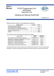
1. Affected product
SM+ for 78K0R Ver. 2.21
2. New restrictions
Restrictions No. 47 to No. 56 and No. 58 to No. 69 on debug functions and restrictions No. 14 and No.
15 on simulation functions have been added. See the attachment for details.
3. Workarounds
See the attachment for details.
4. Modification schedule
All restrictions added to this edition will be corrected in the next version (planned for release in
December 2008).
Correction of restriction No. 69 on debug functions is under discussion.
5. List of restrictions
A list of restrictions in SM+ for 78K0R, including the revision history and detailed information, is
described on attachment.
6. Revision history
Document Number
ZBG-CD-08-0037
Date Issued
September 25, 2008
Description
Newly created.
ZBG-CD-08-0037
Attachment - 1/30
Restrictions on SM+ for 78K0R
1. Product History
This section explains the restrictions on SM+ for 78K0R. The restrictions are classified into the following
two types.
• Restrictions on debug functions
• Restrictions on simulation functions
The following items have been deleted from the previous edition (ZUD-CD-06-0131).
• Restrictions that have been moved to user’s manual
• Similar restrictions that have been integrated
• Inapplicable restrictions
The number assigned to each restriction has not been changed from that used in the previous edition
(ZUD-CD-06-0131).
ZBG-CD-08-0037
Attachment - 2/30
1.1 Restrictions on Debug Functions (List)
The following table lists the restrictions related to CHAPTER 5 DEBUG FUNCTION in SM+ System
Simulator Operation User’s Manual (U18601EJ1).
Restrictions No. 48, 49, 52, 53, 59 to 63, and 65 to 67 are applicable only when the μPD78F1166 is
specified in the device file.
No.
Description
Version
V2.20
V2.21
1
Restriction on setting access breaks (1)
×
×
3
Restriction on searching the memory (1)
×
{
6
Restrictions on adding SFRs to Add I/O Port dialog box
×
×
10
Restriction on coverage functions (1)
×
×
13
Restriction on downloading a HEX file
×
{
15
Restriction on moving from Trace View window (1)
×
Δ
17
Restrictions on Watch window (1)
×
Δ
18
Restrictions on [Trace Size] in Extended Option dialog box
×
×
20
Restriction on rewriting PSW bits in DMM dialog box
×
×
22
Restriction on time measurement when a section trace is set
×
{
24
Restriction that the display partially appears blank in Memory window
×
×
25
Restriction that change in Snap Shot setting is not reflected
×
{
26
Restriction on changing font size
×
×
29
Restriction on Assemble Search dialog box
×
×
30
Restriction on move via Address Move dialog box (1)
×
×
31
Restriction on Memory Compare dialog box
×
{
33
Restriction on Stack window
×
×
34
Restriction on event links
×
{
35
Restriction on changing Register window size
×
{
39
Restriction on stub function
×
×
42
Restriction on path name length
×
×
43
Restriction on the display of the bit variables in the Sym Inspect window
×
×
44
Restriction on setting breakpoint to address immediately after conditional skip
×
{
×
{
instruction
45
Restriction on Return Out when PC position does not change before and after
execution
46
Restriction whereby standard I/O function interface addresses cannot be accessed
×
{
47
Restrictions on setting break points
×
×
48
Restrictions on flash self programming functions
×
×
49
Restriction on oscillation stabilization time
×
×
50
Restriction on trace on PREFIX instruction (5-byte length)
×
×
51
Restriction on setting access breaks (3)
×
×
52
Restrictions on timer array units (1)
×
×
53
Restrictions on serial array units (1)
×
×
{: Corrected, Δ: Partially corrected, ×: Will be corrected in the next version
ZBG-CD-08-0037
No.
Attachment - 3/30
Description
Version
V2.20
V2.21
54
Restriction on Code Coverage window
×
×
55
Restriction on debugging assembler sources
×
×
56
Restriction on conditional trace
×
×
57
Skipped
58
Restriction whereby internal ROM area is illegally rewritten
×
×
59
Restriction on timer array units (2)
×
×
60
Restrictions on serial array units (2)
×
×
61
Restriction on real-time counter
×
×
62
Restriction on clock output/buzzer output controller
×
×
63
Restriction on DMA controller
×
×
64
Restriction on standby function
×
×
65
Restriction on binary-coded decimal (BCD) circuit
×
×
66
Restrictions on timer array units (3)
×
×
67
Restriction on watchdog timer
×
×
68
Restriction on HALT mode
×
×
69
Restriction on division mode of multiplier/divider
×
×
{: Corrected, Δ: Partially corrected, ×: Will be corrected in the next version
ZBG-CD-08-0037
Attachment - 4/30
1.2 Restrictions on Simulation Functions (List)
The following table lists the restrictions related to CHAPTER 6 SIMULATION FUNCTION in SM+
System Simulator Operation User’s Manual (U18601EJ1), and the restrictions related to SM+ System
Simulator User Open Interface User’s Manual (U18212EJ2).
The functions described in the following restrictions are available only when the μPD78F1166 is
specified in the device file.
No.
Description
Version
V2.20
V2.21
3
Restriction on opening and closing Serial window
×
×
10
Restriction whereby a window selected via [Simulator] menu is opened, closed or
×
×
×
×
edited during program execution
13
Restriction related to reception completion callback when using user open
interface CSI
14
Restriction on operations during program execution
×
×
15
Restriction on Serial window (CSI master mode)
×
×
×: Will be corrected in the next version
ZBG-CD-08-0037
Attachment - 5/30
2. Restrictions
2.1 Restrictions on Debug Functions (Details)
This section describes the restrictions related to CHAPTER 5 DEBUG FUNCTION in SM+ System
Simulator Operation User’s Manual (U18601EJ1).
Restrictions No. 48, 49, 52, 53, 59 to 63, and 65 to 67 are applicable only when the μPD78F1166 is
specified in the device file.
No. 1
Restrictions on setting access breaks (1)
[Description]
(1) A variable other than global cannot be specified for an access break in the Watch window.
(2) A variable other than global cannot be specified for an access break in the Source window.
[Workaround]
To set an access break to a static variable in a function, perform the setting in the Event dialog box
while the current PC line is in that function. To set an access break to a static variable in a file,
perform the setting in the Event dialog box while the current PC line is in that file.
[Action]
Both (1) and (2) will be corrected in the next version.
Following this correction, setting of access breaks in the Watch window will be available only for
static variables.
Setting of access breaks in the Watch window will be available only for static variables registered in
the Add Watch dialog box in the following formats.
• Static variables in a function:
file-name#function-name#variable-name
• Static variables in a file:
file-name#variable-name
One restriction is added along with this restriction. Refer to No. 51 Restriction on setting access
breaks (3) for details.
No. 3
Restriction on searching the memory (1)
[Description]
If an unmapped area or a range that includes an SFR area is included in the search range specified
in the Memory Search dialog box, search will also be performed for such areas.
If a mirror area or general-purpose register area is included in the search range, search will not be
performed for such areas.
[Workaround]
Do not include unmapped areas, SFR areas, mirror areas, or general-purpose register areas in the
search range.
[Action]
This issue has been corrected in V2.21.
ZBG-CD-08-0037
No. 6
Attachment - 6/30
Restrictions on adding SFRs to Add I/O Port dialog box
[Description]
The following restrictions apply when registering SFRs in the Add I/O Port dialog box (dialog box
used when an SFR name is redefined with another name in a C source).
(1) If a R/W-attribute SFR is registered as a W-attribute register with another name, the SFR is
registered in the Add Watch window and its value is changed in the Watch window, values
displayed in the SFR window are not updated.
(2) Registration of SFRs for the 2nd SFR area is not available (if attempted, an error occurs.)
(3) If an SFR that satisfies the following two conditions is registered, registration is possible but an
error occurs when an attempt is made to display the registered SFR by using the [Move]
command of the context menu (right-click menu) in the SFR window (move fails).
• The name of the SFR to be registered is used for a general-purpose register
• The address to be registered is the same as that of an SFR area (different from the
address of the general-purpose register.)
[Workaround]
(1) When changing values in the Watch window, input the value two or more times, or change the
values in the SFR window.
(2) There is no workaround.
(3) There is no workaround.
[Action]
All (1) through (3) will be corrected in the next version.
After correction of (3), specifications have been changed so that SFRs having the same names as
general-purpose registers will not be able to be registered. If it is attempted to be changed, the error
“Ff900: Illegal I/O port name” occurs.
No. 10 Restrictions on coverage functions (1)
[Description]
(1) Coverage files (*.cvb) cannot be uploaded.
(2) If the Code Coverage window is displayed at the front when the code coverage is cleared, the
access monitor status in the Memory window may not be cleared.
[Workaround]
(1) There is no workaround.
(2) Clear the code coverage again.
[Action]
Both (1) and (2) will be corrected in the next version.
ZBG-CD-08-0037
Attachment - 7/30
No. 13 Restriction on downloading a HEX file
[Description]
If a HEX file is downloaded while “Load Module (*.lnk;*.lmf)” is specified as the file type in the
Download dialog box, no error is output even if an illegal value is input as the offset.
[Workaround]
Specify “Hex Format” in the [Files of type] list box and then download the hex file.
[Action]
This issue has been corrected in V2.21.
Following this correction, no values can be input to the [Offset Address] text box (this box appears
dimmed and unavailable) when “Load Module (*.lnk;*.lmf)” is selected in the [Files of type] list box.
No. 15 Restrictions on moving from Trace View window (1)
[Description]
(1) If the Trace Data Select dialog box is opened via the Trace View window with the mixed display
hidden, the [Frame] check box is cleared, and then the [Frame No.] radio button is selected in
the Trace Move dialog box, the view may move to an unexpected frame.
(2) If the Trace Move dialog box is opened via the Trace View window, menu items other than “Last
Frame” are not displayed in the [Frame No.] drop-down list.
(The input history should be
displayed.)
(3) If the “Frame No.” radio button is selected and “First” or “Last” is specified in the drop-down
combo box in the Trace Move dialog box, the view will move to an invalid location.
(4) If the “1st frame of last block” radio button is specified, or “First” or “S” is specified for “Frame
No.” in the Trace Move dialog box, the view in the Trace View window may become invalid. (For
example, data is displayed as “???”, or the same trace information is displayed in two lines.)
[Workaround]
(1) Be sure to use the Trace Move dialog box while frame numbers are displayed in the Trace View
window.
(2) There is no workaround.
(3) If the [Frame No.] radio button is selected in the Trace Move dialog box, specify the frame
number using numeric values.
(4) Refresh the Trace View window contents by taking a measure such as clicking the [Refresh]
button in the Trace View window, or scrolling down the screen once and then scrolling up again.
[Action]
Items (1) through (3) have been corrected in V2.21.
Item (4) will be corrected in the next version.
ZBG-CD-08-0037
Attachment - 8/30
No. 17 Restrictions on Watch window (1)
[Description]
(1) If a general-purpose register is registered in the Watch window, the displayed data digit may be
incorrect. (For example, instead of the values of the PC register being displayed with five digits,
they are displayed with four.)
(2) If the item at the bottom of the list is deleted in the Watch window, the [Refresh] button appears
dimmed and is no longer available. In such a case, close the Watch window and then open it
again.
[Workaround]
(1) To reference the general-purpose register values, use the Register window.
(2) Close the Watch window and then open it again.
[Action]
Both (1) and (2) will be corrected in the next version.
No. 18 Restriction on [Trace Size] in Extended Option dialog box
[Description]
An error occurs if 6M or more frames are specified in the [Trace Size] field of the Extended Option
dialog box and the [OK] button is clicked.
[Workaround]
There is no workaround.
[Action]
This issue will be corrected in the next version.
Following this correction, the maximum value that can be selected in [Trace size] has been changed
to 6M frames.
No. 20 Restriction on rewriting PSW bits in DMM dialog box
[Description]
When changing register values in the DMM dialog box, the error message “A9004: Too large register
size.” will be displayed if a PSW bit (IE, Z, RBS1, AC, RBS0, ISP1, ISP0, or CY) is specified in the
[Register Name] field, but this error message is incorrect.
[Workaround]
To change the PSW values in the DMM dialog box, specify the PSW, not its bits. To change only the
values of the PSW bits, change them in the Register window after the program is stopped.
[Action]
The error message will be corrected in the next version.
The error message after the correction is as follows.
“A9006: Please change PSW register not by 1-bit but by 8-bits.”
ZBG-CD-08-0037
Attachment - 9/30
No. 22 Restriction on time measurement when a section trace is set
[Description]
When a section trace is set in the Trace dialog box, a timer event is set in the Timer dialog box, then
the program is executed, the trace result may not be displayed in the Trace View window after
completion of the execution.
[Workaround]
If the trace result is not displayed, perform step-wise execution once.
[Action]
This issue has been corrected in V2.21.
No. 24 Restriction that the display partially appears blank in Memory window
[Description]
When the Memory window is displayed in front of another window, if the window behind the Memory
window is clicked to the front and then the Memory window is clicked to the front again, the line
where the caret was placed and the portion which was overlapped by the other window appear blank
in the Memory window.
The line where the caret was placed and the portion which was
overlapped by the other window appear blank.
[Workaround]
Click the [Refresh] button or click on the blanked line to restore the original display.
[Action]
This issue will be corrected in the next version.
ZBG-CD-08-0037
Attachment - 10/30
No. 25 Restriction that change in Snap Shot setting is not reflected
[Description]
When ”Memory” is selected in the Select field and a label is specified in the Address field in the Snap
Shot dialog box, if the address of the registered label is changed in line with a user program
modification, the address before modification is snapped and displayed.
[Workaround]
When the address of the registered label is changed, re-register the snap information using the
[Change] button.
[Action]
This issue has been corrected in V2.21.
No. 26 Restriction on changing font size
[Description]
The font size in the Watch window and Local Variable window can be specified in the [Font] area in
the Debugger Option dialog box, which is opened by selecting the [Option] menu → [Debugger
Option...], but if the font size is reduced, information from before changing the font size remains in
the window.
Example of Watch window:
Font size: Large
Font size: Small
Information from before changing the font size remains.
[Workaround]
When such a case occurs, minimize the window once and then restore the window size, or close the
window once and then open it again.
[Action]
This issue will be corrected in the next version.
ZBG-CD-08-0037
Attachment - 11/30
No. 29 Restriction on Assemble Search dialog box
[Description]
If an address is input to the “Address” text box in the Assemble Search dialog box, the search may
not be performed normally.
Specifically, the actually searched range may be 0x400 space (1 KB) shorter than the range
specified. Consequently, the search may fail even if the relevant data exist in the search range.
[Workaround]
Specify an additional 0x400 space (1 KB) for the search target range.
[Action]
This issue will be corrected in the next version.
After the correction, the data is searched for the exact specified range.
No. 30 Restriction on move via Address Move dialog box
[Description]
If the Address Move dialog box is opened by selecting the [Move] command from the context menu
(right-click menu) in the Memory window and the last address (0xfffff) is input, an extra line may be
displayed.
An extra line may
be displayed.
[Workaround]
Do not move to address 0xfffff. (This address is in the SFR area, so displaying this area in the
Memory window is meaningless.)
[Action]
This issue will be corrected in the next version.
No. 31 Restriction on Memory Compare dialog box
[Description]
If a symbol (function name, label, variable name, or the like) is specified for the compare address in
Memory Compare dialog box, the compare range may be invalid.
[Workaround]
Input the address directly.
[Action]
This issue has been corrected in V2.21.
ZBG-CD-08-0037
Attachment - 12/30
No. 33 Restriction on Stack window
[Description]
The Stack window cannot be used. (The related menus and buttons appear dimmed so this window
cannot be opened.)
[Workaround]
There is no workaround.
[Action]
This issue will be corrected in the next version.
Whether the result of tracing by the stack trace function is correct varies depending on the state of
the stack. Following this correction, the specification of the view will be changed as follows.
[Stack Trace Window]
If the result is correct, the
background color remains
white.
If the result may be incorrect, the
background color turns gray.
[Execution of where command in Console window]
The message “--- Information below might be inaccurate.” will
be displayed between a line in which the result is correct and
a line in which the result may be incorrect.
No. 34 Restriction on event links
[Description]
If an event is created with “Register” or “Memory” specified from the Event Status drop-down list in
the Event dialog box, only Phase 1 can use this event as an event link condition. The event can be
specified for Phase 2 and later, but does not operate normally.
[Workaround]
Do not set such events as the event link condition [Phase2] or later.
ZBG-CD-08-0037
Attachment - 13/30
[Action]
This issue has been corrected in V2.21.
The following error will occur if the above setting is performed in the corrected version.
No. 35 Restriction on changing Register window size
[Description]
When the size of the Register window is changed, the project is saved and the project is reloaded,
and the position of the split bar may not be restored. Consequently, the contents of some registers
may be hidden.
The position of this bar may not be restored.
[Workaround]
There is no workaround.
[Action]
This issue has been corrected in V2.21.
No. 39 Restriction on stub function
[Description]
If a stub event is set and the program is executed, the operation becomes illegal.
After program execution, functions such as Step-In will no longer operate. Data displayed in the
Assemble window or Memory window also becomes invalid. Therefore, do not use stub events.
[Workaround]
If the operation becomes illegal, delete the stub event, save the project file as a new file, and then
restart the simulator.
[Action]
This issue will be corrected in the next version. (The stub function will be removed.)
ZBG-CD-08-0037
Attachment - 14/30
No. 42 Restriction on path name length
[Description]
Windows supports path names (including file name) consisting of up to 259 single-byte characters,
but the simulator cannot use 256 or more characters for path names. If 256 or more characters are
used for path names, the operation becomes invalid. (For example, if the path for a load module file
is too long, the file cannot be downloaded even if attempted, or if the path for a source file is too long,
the source file cannot be opened.)
[Workaround]
Specify path names using up to 255 characters, including the file name.
[Action]
This issue will be corrected in the next version.
Following this correction, the usable character length for path names will be extended to 259
characters (the maximum value supported by Windows).
No. 43 Restriction on the display of the bit variables in the Sym Inspect window
[Description]
The addresses for bit variables may not be displayed correctly in the Sym Inspect window.
[Workaround]
There is no workaround.
[Action]
This issue will be corrected in the next version.
No. 44 Restriction on setting breakpoint to address immediately after conditional skip instruction
[Description]
If a breakpoint is set to an instruction that will be skipped by a conditional skip instruction (SKC,
SKNC, SKZ, SKNZ, SKH, or SKNH), the skip will not occur regardless of whether or not the skip
condition is satisfied. As a result, a break always occurs.
[Workaround]
There is no workaround.
[Action]
This issue has been corrected in V2.21.
No. 45 Restriction on Return Out when PC position does not change before and after execution
[Description]
If the address pointed to by the program counter (PC) before Return Out execution is the same as
the address at which the execution will stop, nothing will be executed even if Return Out is executed.
[Workaround]
Execute step-wise execution once to change the address, and the execute Return Out.
[Action]
This issue has been corrected in V2.21.
ZBG-CD-08-0037
Attachment - 15/30
No. 46 Restriction whereby standard I/O function interface addresses cannot be accessed
[Description]
If an access, such as downloading data or writing via an instruction, is performed for a standard I/O
function interface address while the standard I/O function is not used, the operation will be ignored.
Although the standard I/O function interface address can be specified in the Simulator Option dialog
box, which is opened by selecting [Simulator Option] from the [Option] menu, it is specified as
0xFFE90 to 0xFFEA3 (internal RAM area) by default. Consequently, the program may malfunction
due to this restriction.
[Workaround]
When the standard I/O function is not used, input “0x200000” to the Interface Address text box in the
Simulator Option dialog box and save the project file as a new file. This can prevent the program
malfunction because address 0x200000 does not exist in the target device.
Input “0x200000” and the save the
project file as a new file.
[Action]
This issue has been corrected in V2.21. (The interface address value will be set to 0x200000 by
default.)
Note, however, that this restriction will still apply, even if a project file created in V2.20 is opened in
SM+ V2.21 or later, because the interface address setting is saved in the project file, according to
the specifications. Therefore, implement the above mentioned workaround when opening a project
file created with V2.20, even if the project file is used in V2.21 or later.
No. 47 Restrictions on setting break points
[Description]
(1) If a break point is set during program execution, the program does not stop at that break point.
(2) If a break point is set during program execution and a forcible break is executed before the
execution stops at the break point, the error message “F0301: User program is being breaked”
is displayed, but the program does not stop.
(3) If a break point is set to the interrupt service function while “After” is selected for [Break
Condition] in the Extended Option dialog box to use a break point as a “break after execution”,
the program does not stop at that break point.
[Workaround]
(1) Do not set break points during program execution.
(2) Do not set break points during program execution.
(3) Use break points as “break before execution” (default setting).
ZBG-CD-08-0037
Attachment - 16/30
[Action]
All (1) through (3) will be corrected in the next version.
No. 48 Restrictions on flash self programming functions
[Description]
(1) When the Blank Check function (FlashBlockBlankCheck) is executed while the maximum block
number prescribed in the target device is specified as “the number of a block to be checked for
blank check”, which is specified for an argument, a blank check error occurs (return value: 0x1b),
even if the specified block is blank.
(2) When the EEPROM Write function (EEPROMWrite) is executed, writing is performed from the
write start address, which is specified for an argument, for the amount of written data. At this
time, if the write start address and the last address of written data are in the same block, all data
in that block and data at addresses later than the written block will become 0x00 (see the figure
below).
Flash Memory Block
Area written by EEPROM write function
Area in which this restriction occurs
(All data in this area become 0x00.)
[Workaround]
There is no workaround for (1) and (2).
[Action]
Both (1) and (2) will be corrected in the next version.
No. 49 Restriction on oscillation stabilization time
[Description]
In the target device, the maximum value of the time counted by the oscillation stabilization time
counter status register (OSTC) depends on the value set to the oscillation stabilization time selection
register (OSTS). In the simulator, it does not depend on the OSTS register and the maximum value
is fixed to 0xff.
[Workaround]
There is no workaround.
[Action]
This issue will be corrected in the next version.
ZBG-CD-08-0037
Attachment - 17/30
No. 50 Restriction on trace on PREFIX instruction (5-byte length)
[Description]
When a 5-byte length PREFIX instruction (“MOV ES:!addr16, #byte”, ”XCH A, ES:!addr16”, etc.) is
executed, the disassemble result displayed in the Trace window becomes “???”. (The instruction is
executed correctly.)
[Workaround]
There is no workaround.
[Action]
This issue will be corrected in the next version.
No. 51 Restriction on setting access breaks (3)
[Description]
When changing an access break setting in the Event dialog box with an in-function static variable
specified in the [Address] field, the error message “F4002: Illegal start address” or “F4003: Illegal end
address” is displayed and setting change fails. An example is shown in the figure below.
Set an access break with global
variable “VAL0” specified.
Double-click the created access
break item.
Change the Address field setting to
the in-function static variable.
ZBG-CD-08-0037
Attachment - 18/30
[Workaround]
Delete the break point and create a new access break point.
[Action]
This issue will be corrected in the next version.
No. 52 Restrictions on timer array units (1)
[Description]
Restrictions on timer array units are described below.
“m” in the following descriptions represents the unit number of a timer array and “n” represents the
channel number of a timer array.
(1) If timer channel stop register m (TTm) is set to 1 while multiple timer channels are operating, all
timer channels including those not being set to 1 also stop at the same time.
In addition, if operation of any channel is started by setting timer channel start register m (TSm)
to 1 while the timer channels are illegally stopped, all illegally stopped channels start operation
at the same time.
(2) If timer output is enabled by setting timer output enable register m (TOEm) after output inversion
is specified with timer output level register m (TOLm), the timer output is not inverted.
(3) When using a PWM function, one-shot pulse function or multiple PWM output function, the first
interrupt that occurs on the master channel side is not recognized as a start trigger on the slave
channel side. For this reason, the width of the active level which is output from the timer output
pin (TOmn) first becomes twice the expected width.
[Workaround]
There is no workaround for (1) through (3).
[Action]
All (1) through (3) will be corrected in the next version.
ZBG-CD-08-0037
Attachment - 19/30
No. 53 Restrictions on serial array units (1)
[Description]
Restrictions on serial array units are described below.
“m” in the following descriptions represents the unit number of a serial array, “n” represents the
channel number of a timer array, and “p” represents the CSI number.
(1) If the serial channel stop register m (STm) is set to 1 while multiple serial channels are operating,
all serial channels, including those not being set to 1, also stop at the same time.
In addition, if operation of any channel is started by setting serial channel start register m (SSm)
to 1 while the serial channels are illegally stopped, all illegally stopped channels start operation
at the same time.
(2) If transmission data is written to serial data register mn (SDRmn), the illegal operation will occur
as follows.
• When using UART: Data is transmitted twice upon one transmit data write.
The same data is transmitted twice. An interrupt occurs twice upon the
data transmission for two times.
• When using CSI:
Data is transmitted once but an interrupt occurs two or three times upon
one transmit data write. (After the simulator is activated, an interrupt
occurs three times for the first transmission and two times in other cases.)
The timing at which interrupts occur is as follows.
• When an interrupt occurs for three times:
Once immediately before transfer, and twice immediately after transfer
• When an interrupt occurs for two times:
Twice immediately after transfer
(3) When using the UART, even if the data length is set to 5 bits using serial communication
operation setting register mn (SCRmn), transmission is performed with the 7-bit data length.
(4) When using the CSI, no overrun error occurs, even in the following situations.
• Even though the receive data is stored in serial data register mn (SDRmn), the transmit data
is written or the next receive data is written before the store data is read.
• Transmit data is not prepared for the slave transmission or transmission/reception in the CSI
mode.
ZBG-CD-08-0037
Attachment - 20/30
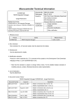
(5) If the DAPmn and CKPmn bits of serial communication operation setting register mn (SCRmn)
are set to 0,0 or 0,1 when using the CSI in the master mode, the serial clock (SCK) will be
output for a period 1 bit shorter than the specified length.
When the data length is set to 7 bits, the serial clock is output only for a 6-bit period.
When the data length is set to 8 bits, the serial clock is output only for a 7-bit period.
Examples in the case of 8-bit data length and MSB first are shown below.
There will be no problem if the DAPmn and CKPmn bits of the SCRmn register are set to 1,0 or
1,1.
[In Target Device]
DAPmn
CKPmn
0
0
0
1
Relationship Between Data and Clock Phases in CSI Mode
(8-bit Data Length, MSB First)
SCKp
SOp
D7
D6
D5
D4
D3
D2
D1
D0
D7
D6
D5
D4
D3
D2
D1
D0
SCKp
SOp
[In Simulator]
DAPmn
Relationship Between Data and Clock Phases in CSI Mode
CKPmn
(8-bit Data Length, MSB First)
The last clock is not output.
0
0
SCKp
SOp
D7
D6
D5
D4
D3
D2
D1
D0
The last clock is not output.
0
1
SCKp
SOp
D7
D6
[Workaround]
There is no workaround for (1) through (5).
[Action]
All (1) through (5) will be corrected in the next version.
D5
D4
D3
D2
D1
D0
ZBG-CD-08-0037
Attachment - 21/30
No. 54 Restriction on Code Coverage window
[Description]
Value “0.0” is displayed in the [Coverage(%)] column on the [Interrupt] tab in the Code Coverage
window, regardless of the occurrence of interrupts. In addition, “----” is displayed in the [Status]
column on the [Interrupt] tab, regardless of the use of interrupt functions.
Display in [Status] column
becomes “----”.
Display in [Coverage(%)]
column becomes “0.0”.
[Workaround]
The [Interrupt] tab is used to check the occurrence of interrupts, but the occurrence can also be
checked by referring to the [Function] tab for the coverage of the function corresponding to the
interrupt.
• When 0.0 is displayed in [Coverage(%)]: Interrupts have not occurred.
• When a value other than 0.0 is displayed in [Coverage(%)]: Interrupts have occurred.
Example When interrupt INTP0 is defined as function “int_p0” and INTP1 as function
“int_p1”
“0.0” is not displayed in
[Coverage(%)], which means
that INTP0 has occurred.
“0.0” is displayed in [Coverage(%)]
column, which means that INTP1
has not occurred.
[Action]
This issue will be corrected in the next version. The operation after correction will be as follows.
• In [Status] column:
“Use” is displayed when the interrupt function is defined, and “nonuse”
is displayed when the interrupt function is not defined.
• In [Coverage(%)] column: “100.0” is displayed when an interrupt has occurred, or “0.0” is
displayed when interrupts have not occurred.
ZBG-CD-08-0037
Attachment - 22/30
No. 55 Restriction on debugging assembler sources
[Description]
If either of absolute expression CSEG AT or ORG is used in an assembler source file and
instructions are allocated to multiple absolute addresses, the following problems may occur at the
last instruction.
• Breakpoints cannot be set
• Mixed display is not available
A problem may occur for this
instruction.
Disassembling of this instruction
is not output or a break cannot
be set for this instruction.
[Conditions under which the problem may occur]
The problem occurs when both the following two conditions are satisfied.
(1) Two or more absolute addresses are specified in an assembler source file.
(2) The absolute address specified nearer to the top of the file is smaller than that specified further
from the top of the file. (In the above example, test1, which is nearer to the top of the file, is
allocated to address 1000H, and test2, which is further from the top of the file, is allocated to
address 0100H, which causes a problem.)
This problem does not affect absolute address specification in link directive files.
[Workaround]
Divide the file so that two or more absolute addresses are not specified in an assembler source file.
Or, rearrange the order of the code so that the absolute addresses are specified from the smaller
one in an assembler source file.
[Action]
This issue will be corrected in the next version.
ZBG-CD-08-0037
Attachment - 23/30
No. 56 Restriction on conditional trace
[Description]
If the value of [Trace Size] is changed in the Extended Option dialog box, which is opened by
selecting [Extended Option] from the [Option] menu, while a conditional trace (qualify trace or section
trace) is being executed, the trace mode is switched to unconditional trace.
* The conditional trace is still selected according to the view in the [Run] menu, but the simulator
executes an unconditional trace.
[Workaround]
When the value of [Trace Size] is changed in the Extended Option dialog box, first select [Conditional
Trace] in the [Run] menu and then execute the program.
Cond. trace On has already been
selected, but click this menu again.
[Action]
This issue will be corrected in the next version.
No. 58 Restriction whereby internal ROM area is illegally rewritten
[Description]
If a program is executed while the following two conditions are satisfied, ROM may be rewritten to
illegal values. As a result, the program execution result also becomes invalid.
(1) Either of the following event functions is used.
• Measurement of interval between events
• Section trace or qualify trace
(2) Either of the Memory window or Watch window is displayed (including in the minimized window
state)
[Workaround]
There is no workaround.
[Action]
This issue will be corrected in the next version.
No. 59 Restriction on timer array units (2)
[Description]
If timer output mode register m (TOMm) is set after timer channel start register m (TSm) is set in the
timer array unit, the write to the timer output mode register is ignored. (m = 0 or 1 (unit number))
[Workaround]
There is no workaround.
[Action]
This issue will be corrected in the next version.
ZBG-CD-08-0037
Attachment - 24/30
No. 60 Restrictions on serial array units (2)
[Description]
(1) When the serial array unit operates in UART mode and the buffer empty interrupt is used as an
interrupt source, the first interrupt occurs after transfer has started, but the second and
subsequent interrupts will not occur.
(2) When the serial array unit operates in CSI mode and the buffer empty interrupt is used as an
interrupt source, and if communication with the Serial window is performed, invalid values are
displayed as the receive values (values displayed for [Receive Data]) in the Serial window.
(3) When serial array unit CSI01 operates in CSI mode, and if transmission/reception with the Serial
window is performed, all data received on the microcontroller side is displayed as “0x00”.
(4) When the serial array unit operates in CSI mode and the buffer empty interrupt is used as an
interrupt source, the following problems occur depending on the value of the DAPmn bit of serial
communication operation setting register mn (SCRmn). (m = 0 or 1 (unit number), n = 0 to 3
(channel number))
When DAP = 0: An overrun error does not occur.
When DAP = 1: An overrun error always occurs at the end of communication.
[Workaround]
There is no workaround for (1) through (4).
[Action]
All (1) through (4) will be corrected in the next version.
No. 61 Restriction on real-time counter
[Description]
The clock specified as the operation clock for the CPU/peripheral hardware clock (fCLK) in the system
clock control register (CKC) is used as the operation clock for the real-time counter. The subclock is
normally used as the operation clock real-time counter, so the real-time counter does not operate
with the desired cycles.
[Workaround]
There is no workaround.
[Action]
This issue will be corrected in the next version.
No. 62 Restriction on clock output/buzzer output controller
[Description]
If output is enabled (PCLOEn = 1) and then disabled (PCLOEn = 0) in the clock output/buzzer output
controller, and if the waveform output from the PCLBUZ0 and PCLBUZ1 pins is at high level when
output is disabled, the alternate function (output port) of the P140 and P141 pins will not be able to
be used. (The output is fixed to high level.) (n = 0 or 1)
[Workaround]
There is no workaround.
ZBG-CD-08-0037
Attachment - 25/30
[Action]
This issue will be corrected in the next version.
No. 63 Restriction on DMA controller
[Description]
If the transfer count is set to 2 to 1024 times (not “1 time”) in DMA byte count register n (DBCn), the
specified amount of data is transferred in response to a single transfer request and a transfer end
interrupt occurs. Consequently, the DMA controller does not operate as expected. (n = 0 or 1
(channel number))
[Workaround]
There is no workaround.
[Action]
This issue will be corrected in the next version.
No. 64 Restriction on standby function
[Description]
If a masked interrupt occurs when the operation is entering standby mode (HALT or STOP), the
standby mode is released. (The standby mode is usually not released even if a masked interrupt
occurs.)
[Workaround]
There is no workaround.
[Action]
This issue will be corrected in the next version.
No. 65 Restriction on binary-coded decimal (BCD) circuit
[Description]
(1) If the ADDC or SUBC instruction is executed, the corrected values are not stored in the BCD
correction result register (BCDADJ).
(2) If either of the following instruction codes is executed while the ES register value is not 0xF, the
BCD correction values are stored in the A or CY register.
• Instruction codes in question: ADD A,ES:!00FEH and SUB A,ES:!00FEH
[Workaround]
There is no workaround for (1) and (2).
[Action]
Both (1) and (2) will be corrected in the next version.
ZBG-CD-08-0037
Attachment - 26/30
No. 66 Restrictions on timer array units (3)
[Description]
(1) When the timer array unit is used in PWM output mode or multiple PWM output mode, the
correct waveform is not output depending on the value set for the duty.
* Timer data register (master channel side) = TDRmn, timer data register (slave channel side) =
TDRmp
• If the value set to TDRmp (slave channel side) is the TDRmn (master channel side) set value
– 2 or more:
When a waveform (PWM waveform) is output from a slave channel, a low level is output for
the first clock cycle. (A high level should be output from the start of output.)
• If the value set to TDRmp (slave channel side) is the TDRmn (master channel side) set value
– 1:
When a waveform (PWM waveform) is output from a slave channel, a high level is output only
in the second cycle. (A PWM waveform with the specified duty should be output.)
• If the value set to TDRmp (slave channel side) is the TDRmn (master channel side) set value
or higher:
When a waveform (PWM waveform) is output from a slave channel, the output form is the
inverted form of the waveform output from the master channel (cycle waveform). (A PWM
waveform with the specified duty should be output.)
(2) When the timer array unit is used in one-shot pulse output mode, the waveforms output from the
target device and the simulator differ.
* Timer data register (master channel side) = TDRmn, timer data register (slave channel side) =
TDRmp
• Waveform output from target device
Delay: {TDRmn (master channel side) set value + 2} × Count clock cycle
Pulse width: {TDRmp (slave channel side) set value} × Count clock cycle
• Waveform output from simulator
Delay: {TDRmn (master channel side) set value + 1} × Count clock cycle
Pulse width: {TDRmp (slave channel side) set value + 1} × Count clock cycle
[Workaround]
(1) There is no workaround.
(2) Increment the TDRmn (master channel side) set value by 1, and decrement the TDRmp (slave
channel side) set value by 1.
[Action]
Both (1) and (2) will be corrected in the next version.
No. 67 Restriction on watchdog timer
[Description]
If the watchdog timer window open period is set to 25% or 50%, the counter is not cleared even if
clearing of the watchdog timer counter is set (writing ACH to the WDTE register). As a result, a reset
occurs.
ZBG-CD-08-0037
Attachment - 27/30
[Workaround]
Set the watchdog timer window open period to 75% or 100%.
[Action]
This issue will be corrected in the next version.
No. 68 Restriction on HALT mode
[Description]
If HALT mode is entered while the D/A converter is operating, the D/A converter stops after the HALT
mode is released. (The D/A converter operation should continue even after the HALT mode is
released.)
[Workaround]
There is no workaround.
[Action]
This issue will be corrected in the next version.
No. 69 Restriction on division mode of multiplier/divider
[Description]
Division does not end if a multiplier/divider is used in the division mode. Depending on the code of
the program, execution may enter an infinite loop or an invalid quotient may be output.
[Workaround]
When a C compiler library is used, clear the [Using Multiplier/Divider] check box in the [Compiler
Options] dialog box of PM+.
Do not use the multiplier/divider in division mode if the program is written in assembly language.
[Action]
Correction is under study.
ZBG-CD-08-0037
Attachment - 28/30
2.2 Restrictions on Simulation Functions (Details)
This section describes the restrictions related to CHAPTER 6 SIMULATION FUNCTION in SM+ System
Simulator Operation User’s Manual (U18601EJ1), and the restrictions related to SM+ System Simulator
User Open Interface User’s Manual (U18212EJ2).
The functions described in the following restrictions are available only when the μPD78F1166 is
specified in the device file.
No. 3
Restriction on opening and closing Serial window
[Description]
If the Serial window is closed during program execution, the simulator may be forcibly terminated.
Also, if the Serial window is closed after executing a program that performs transmission or reception
between the Serial window and then reexecution of the program is attempted, the simulator may be
forcibly terminated.
[Workaround]
Close the Serial window before running the program or minimize the Serial window instead of closing
it. (There will be no problem if the Serial window is minimized.)
If you closed the Serial window during or after program execution, overwrite the project file for saving
and then terminate the simulator. When the simulator is started the next time, the overwritten project
file will be loaded and thus the simulator can restore the normal status.
[Action]
This issue will be corrected in the next version. Following this correction, the Serial window will not
be able to be opened or closed during program execution.
No. 10 Restriction whereby a window selected via [Simulator] menu is opened, closed or edited during
program execution
[Description]
If any of the following windows, selected via the [Simulator] menu on the menu bar, is opened or
closed during program execution, the simulator may deadlock or may be forcibly terminated.
• Signal Data Editor window including information on connected pins
• Timing Chart window including information on connected pins
• I/O Panel window including information on connected pins
There will be no problem if the window is minimized, or if a window not including information on
connected pins is opened or closed.
Whether the window includes information on connected pins can be judged as shown below.
ZBG-CD-08-0037
Attachment - 29/30
• If the window does not include pin connection information (Opening/closing the window causes no
problem.)
Signal Data Editor window:
No pins are selected.
Timing Chart window:
No pins are selected.
I/O Panel window:
No parts are connected or
nothing is selected in Pin Name.
• If the window includes pin connection information (Do not open/close the window.)
Signal Data Editor window:
One or more pins are selected.
Timing Chart window:
One or more pins are selected.
I/O Panel window:
One or more parts are connected
and a pin is selected in Pin Name.
In addition, if connection pins are added or deleted in the Signal Data Editor window during program
execution, the simulator may deadlock or may be forcibly terminated.
[Workaround]
Stop program execution before opening, closing or editing the above windows.
[Action]
This issue will be corrected in the next version. Following this correction, the above windows will not
be able to be opened or closed during program execution. (An error will be output or the above
windows will not be able to be opened, closed or edited.)
No. 13 Restriction related to reception completion callback when using user open interface CSI
[Description]
With the user-open serial interface CSI, if a data transmission function SuoSendSerialData(),
SuoSendSerialDataList(), or SuoSendSerialFile() is used in a serial reception callback function
ReceiveSerialFunc(), data transmission is not executed.
[Workaround]
To direct transmission using SuoSendSerialData(), SuoSendSerialDataList() or SuoSendSerialFile()
in a serial reception callback function ReceiveSerialFunc(), observe the following.
First, set the time setting function of the timer as SuoSetTimer(hTim1, SUO_MAINCLK, 1); (where
the timer’s handle is “hTim1”) without directing transmission in ReceiveSerialFunc().
Next,
direct
transmission
using
SuoSendSerialData(),
SuoSendSerialDataList()
SuoSendSerialFile() in the time report callback function NotifyTimerFunc of the timer.
[Action]
This issue will be corrected in the next version.
or
ZBG-CD-08-0037
Attachment - 30/30
No. 14 Restriction on operations during program execution
[Description]
If one of the following operations is performed during program execution while a window that can be
opened via the [Simulator] menu in the simulator (signal data editor window, I/O Panel window, etc.)
is open, any of the following problems occurs.
[Operations in question]
• CPU reset
• Restart
• Setting, deletion or change of a breakpoint
[Problems that may occur]
• The simulator hangs up and key inputs will no longer be active
• The status bar remains highlighted in red, which means that the program is running. If the
program stop button is clicked, the message “F0301: User program is being breaked.” will be
output.
[Workaround]
Execute the above operations while the program is not running.
[Action]
This issue will be corrected in the next version.
No. 15 Restriction on Serial window (CSI master mode)
[Description]
When the Serial window is used in the CSI master mode, the settings of the Data Phase and Clock
Phase fields in the [Format (CSI)] dialog box will not be reflected in the waveform output from the
Serial window. As a result, transmission and reception are not performed correctly.
The settings of these fields will not be
reflected in the operation correctly.
[Workaround]
There is no workaround.
[Action]
This issue will be corrected in the next version.