1
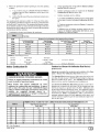
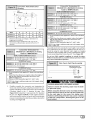
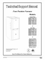
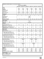
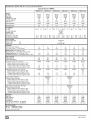
N9MP1 & N9MP2
*9MPD
*Denotes
Brands
90 Single
Stage
(C, H, T)
Category
IVFurnace
FANASSISTED,DIRECTOR
NON-DIRECTVENTGASFURNACE
REQUIREMENTS
SAFETY
Recognize
safety
the potential
for personal
Understand
most serious
death.
information.
words
hazards,
those
CAUTIONis
suggestions
and servicing
repair,
service
by trained
Follow
all
heating
or service
performed
the unit
codes.
Code
CSA
(NSCNGPIC)
These
and service
instructions
personal
unsafe
practices
that could
cover
in enhanced
installation,
These
injury
words
or death.
result
on the furnace
and in instructions
are used with the safety-alert
WARNING
in minor
reliability,
can be hazardous
perform
and other
In the
No. 54-2002.
or CAUTION.
in severe
personnel.
Z223.1-2002/NFPA
procedures
you see this symbol
manuals
be alert to
signifies
personal
injury
a hazard
or product
symbol.
that could
and property
DANGER
result
identifies
in personal
damage.
the
injury
or
Note is used to
or operation.
due to gas and electrical
components.
Only trained
and qualified
personnel
should
equipment.
can
service
WARNING,
equipment
heating
personnel
with
safety
When
result
that will result
Untrained
to or shipped
DANGER,
that will
used to identify
Installing
alert symbolZ_.
injury.
the signal
highlight
install,
This is the safety-
basic
When
safety
United
precautions
States,
In Canada,
B149.1-05.
maintenance
working
Wear
follow
functions
on heating
that may
all
safety
glasses
as cleaning
observe
and replacing
precautions
air filters.
All other
in the literature,
operations
must
on tags, and on labels
be
attached
apply.
safety
refer tothecurrent
such
equipment,
codes
edition
and work
including
the
of the National
gloves.
Have
current
edition
Standard
National
of Canada
fire extinguisher
Fuel
Natural
available
Gas
Code
(NFGC)
Gas and Propane
during
start-up
ANSI
Installation
and adjustment
calls.
minimum
requirements
and conform
exceed certain local codes and ordinances,
especially
those
these instructions
as a minimum
for a safe installation.
to existing
national
standards
and safety
that may not have kept up with changing
codes.
In some instances,
residential
construction
INSTALLER:
on or adjacent
these
instructions
practices.
We require
Affix these instructions
to the furnace.
CONSUMER:
Retain these
instructions for future reference.
International
Comfort
Products,
Lewisburg, TN 37091 U.S.A.
LLC
Table of Contents
1. SafeInstallationRequirements.................
2. Installation ................................
3. Combustion & Ventilation Air ..................
4.Vent & Combustion Air Piping ................
5. GasSupply and Piping ......................
6. Electrical Wiring ...........................
ELECTRIC SHOCK HAZARD
Failure to follow safety
warnings exactly could result
in serious injury and/or death.
Turn Off All Power Before
Servicing.
Printed
inU.S.A.
3
4
8
12
30
37
7. Ductwork and Filter
........................
37
8. Checks and Adjustments ....................
9. Furnace Maintenance .......................
39
42
10. Sequence of Operation & Diagnostics ..........
11. Concentric Vent Termination .................
44
45
Tech Support and Parts ........................
47
CARBON MONOXIDE POISONING AND FIRE
HAZARD.
Failure to follow safety warnings exactly could
result in serious injury, death, and/or property
damage.
This furnace is not designed for use in mobile
homes, trailers or recreational vehicles.
11/28/2005
440 01 1021 (02)
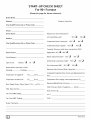
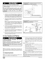
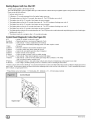
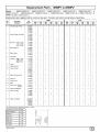
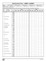
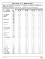
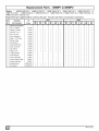
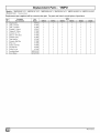
START-UP
CHECK SHEET
For 90+ Furnace
(Keep
this
page
for future
reference)
Dealer Name:
Address:
Business Card Here
City, State(Province),
Zip or Postal Code:
Phone:
Owner Name:
Manual Gas Shut-Off Upstream
YES [_
of Furnace/Drip- Leg?
Address:
NO
YES [_
Condensate Drain Connected?
City, State(Province),
NOE_I
Zip or Postal Code:
Condensate Drain Trapped?
NO
YES [_
Transition Pressure switch hose relocated for U/D/H
Model Number:
Application? YES [_
NO [_
Serial Number:
Blower Speed Checked?
YES [_
All Electrical Connections Tight?
Type of Gas:
Natural:
[_
LP:
NO [_
NOE_I
YES [_
[_
Gas Valve turned ON?
YES [_
NO [_
Which blower speed tap is used?
(Heating)
Measured Line Pressure When Firing Unit:
(Cooling).
Calculated Firing Rate:(See Checks and Adjustments SecTemperature of Supply Air:
(°F)
Temperature of Return Air:
(°F)__.or(°C).
Rise (Supply Temp.-Return
Temp.): (°F)
or(°C)
tion).
Temperature Rise (supply-return
or(°C)__
temperature):(°F)__
Measured Manifold Gas Pressure:
Static Pressure (Ducts): Supply Air
Return
Filter Type and Size:
Date of Start-Up:
Fan "Time ON" Setting:.
Fan "Time OFF" Setting:
Dealer
E_
CO?
CO2 ?
Comments:
44001102102
1. Safe Installation
Requirements
FIRE, EXPLOSION, AND ASPHIXIATION
HAZARD
Improper
adjustment,
alteration,
service,
maintanence
or installation
could cause death,
personal injury and/or property damage.
Installation or repairs made by unqualified persons
could result
in hazards
to you and others.
Installation MUST conform with local codes or, in
the absence of local codes, with codes of all
governmental authorities havingjurisdiction.
adequate
nace as specified
these instructions.
combustion
and ventilation
in "3. Combustion
A,
Always install furnace to operate within the furnace's
intended temperature-rise
range with a duct system which
has an external static pressure within the allowable range,
as specified
in "Technical
Support Manual"
of these instructions.
See furnace rating plate.
When a furnace is installed so that supply ducts carry air
circulated
by the furnace to areas outside the space containing the furnace, the return air shall also be handled by a
duct(s) sealed to the furnace casing and terminating
outside the space containing
the furnace.
furnace
This furnace
buildinq.s
44001 102102
for installation
as specified
is not to be used
or structures
under
in a residential
garage
in "2. Installation"of
these
for temporary
construction.
heating
•
Install
•
Unit MUST be installed so electrical components
tected from direct contact with water.
correct
and return
in mo-
air ducts.
filter type and size.
are pro-
of
and/or improper
use can shorten
hazards for you, the owner.
the life of the unit and
The U.S. Consumer Product Safety Commission encourages
installation of carbon monoxide alarms. There can be various
sources of carbon monoxide in a building or dwelling. The
sources could be gas-fired clothes dryers, gas cooking
stoves, water heaters, furnaces, gas-fired fireplaces, wood
fireplaces.
injury and/or
and odorless
or when the
Therefore,
to help alert people of potentially dangerous
ca rbon
monoxide
levels, you should have a commercially
available
carbon monoxide
alarm that is listed by a nationally
recognized testing agency in accordance
with Underwriters
Laboratories Inc. Standard
for Single and Multiple Station Carbon
Monoxide
Alarms, ANSI/UL
2034 or the CSA 6.19-01
Residential Carbon Alarming Devices installed and maintained
in
the building or dwelling concurrently
with the gas- fired furnace
installation
(see Note below). The alarm should be installed as
recommended
by the alarm manufacturer's
installation
instructions.
Air" of
Never test for gas leaks with an open flame. Use a commercially available soap solution made specifically
for the
detection of leaks to check all connections,
as specified in
"6. Gas Supply and Piping, Final Check"of
these instructions.
must be installed
instructions.
supply
gas produced when fuel is not burned completely
flame does not receive sufficient oxygen.
air to the fur-
Combustion
products must be discharged
outdoors.
Connect this furnace to an approved
vent system only, as specified in "4. Vent and Combustion
Air Piping" of these
instructions.
A gas-fired
Seal around
Carbon
monoxide
can cause serious
bodily
death. Carbon monoxide
or "CO" is a colorless
as speci-
and Ventilation
•
abuse
create
Use only the Type of gas approved
for this furnace
(see
Rating Plate on unit). Overfiring
will result in failure of heat
exchanger
and cause dangerous
operation.
(Furnaces
can be converted
to L.R gas with approved
kit.)
Provide
is NOT approved
for installation
trailers
or recreation
vehicles.
Your unit is built to provide many years of safe and dependable
service providing
it is properly installed and maintained.
However,
NOTE: This furnace is design-certified by the CSA International
(formerly AGA and CGA) for installation in the United States and
Canada. Refer to the appropriate codes, along with this manual,
for proper installation.
•
This furnace
bile homes,
Safety Rules
The information
contained
in this manual is
intended for use by a qualified service agency that
is experienced
in such work, is familiar with all
precautions
and safety procedures
required
in
such work, and is equipped with the proper tools
and test instruments.
Install this furnace only in a location and position
fied in "2. Installation"of
these instructions.
•
B,
There can be numerous
sources of fire or smoke in a building
or dwelling.
Fire or smoke can cause serious
bodily injury,
death, and/or property
damage.
Therefore,
in order to alert
people of potentially dangerous
fire or smoke, you should have
fire extinguisher
and smoke alarms listed by Underwriters
Laboratories
installed and maintained
in the building or dwelling
(see Note below).
Note:
The manufacturer
of your furnace does not test any alarms
and makes no representations
regarding any brand or type
of alarms.
C.
To ensure safe and efficient
do the following:
operation
of your unit, you should
1.
Thoroughly
read this manual and labels on the unit. This
will help you understand
howyour
unit operates and the hazards involved with gas and electricity.
Do not use this unit if any part has been under water. Immediately call a qualified service technician to inspect the unit
and to replace any part of the control system and any gas control which has been under water.
Never obstruct
the vent grilles,
or any ducts that provide
air to the unit. Air must be provided
for proper combustion
and ventilation
of flue gases.
C21
Have someone
check the structure
frequently
during cold
weather to make sure it is warm enough to prevent pipes
from freezing. Instruct them on a service agency to call to
provide service, if required.
FrozenWater Pipe Hazard
WATER DAMAGE TO PROPERTY HAZARD
-or-
Failure to protect against the risk of freezing
result in property damage.
may
Do not leave your home unattended for long periods
during freezing weather without turning off water
supply
and draining
water pipes or otherwise
protecting
against the risk of frozen pipes and
resultant damage.
Your furnace is designed
solely to provide a safe and comfortable
living environment.
The furnace is NOT designed
to ensure that
3.
Winter Shutdown
If you go away during the winter months and do not leave the heat
on in your home, the plastic transition
box and the condensate
trap
on the furnace
must be protected
from freeze
damage.(See
Figure 10 trough Figure 19)
1.
water pipes will not freeze. It is equipped
with several safety devices that are designed
to turn the furnace off and prevent it from
restarting
in the event of various potentially
unsafe conditions.
If your furnace remains off for an extended time, the pipes in your
home could freeze and burst, resulting
in serious water damage.
If the structure will be unattended
take these
precautions.
1.
during
cold weather
Turn off the water supply to the structure
you should
and drain the water
lines if possible and add an antifreeze
for potable water to
drain traps and toilet tanks. Open faucets in appropriate
areas.
-or-
Install a reliable remote sensing device that will notify somebody of freezing conditions
within the home.
Disconnect
the 5/8" OD rubber hose from the vent drain fitting that is located downstream
of the combustion
blower.
Insert a funnel into the hose and pour four(4) ounces of sanitary type (RV) antifreeze
into the condensate
trap. Reconnect the 5/8" OD rubber hose to the stub on the vent drain
fitting.
2.
Secure
Disconnect
with the hose clamp.
the 3/4" OD rubber
hose from the condensate
trap. Insert a funnel into the hose and and pour four(4)
ounces of sanitary type (RV) antifreeze into the plastic Transition box. Squeeze
the hose together near the end and
quickly reconnect the 3/4" OD rubber hose to the stub on the
condensate
trap. Secure with the hose clamp.
When you return home, your furnace
not necessary
to drain the antifreeze
will be ready to start, as it is
from the furnace.
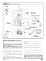
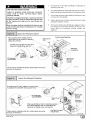
2. Installation
Typical Upflow Installation
CARBON MONOXIDE POISONING HAZARD
Aluminum
Failure to properly
vent this furnace
or other
appliances could result in death or personal injury.
This furnace
can NOT be common
vented or
connected to any type B, BW or L vent or vent
connector, nor to any portion of a factory-built
or
masonry chimney. If this furnace is replacing a
3reviously
common-vented
furnace, it may be
necessary to resize the existing vent and chimney to
3revent oversizing
problems
for the other
remaining appliance(s). See Venting and Combustion Air Check in Gas Vent Installation section. This
furnace MUST be vented to the outside.
or non-rusting
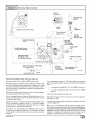
Vent Termination
8" Min. _1
_[_nlet
20Max
in same
atmospheric
_
_
Shielding
Pipe(not
used on Single
shield recommended.
(See
for dimensions).
Couplingon ends of
exhaust pipe.Total
_pipe & coupling out-
Pipe model)
zone
Vent PipesMUST be
'
in.
supportedHorizonta]l
and Vertically
_atmosphedc'
ax.
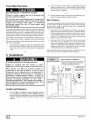
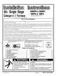
Location and Clearances
1,
E_I
Refer to Figure 1 or Figure 2 for typical installation
and basic connecting
parts required.
Refer to Figure 5 for typical
horizontal direct vent installation
and basic connecting
parts
required. Supply and return air plenums and duct are also
required.
* Increase minimum from 8" to 18" for cold climates (sustained temperatures below
0 ° F).
25-23-33
44001 102102
2.
This furnace is NOT to be used for temporary heat of buildings
or structures under construction.
3.
Install the vent pipes
Installation
section).
4.
Do NOT install furnace directly on carpeting,
bustible material other than wood flooring.
5.
Maintain clearance
for fire safety and servicing. A front clearance of 30" is minimum for access to the burner, controls and
filter. See clearance
requirements
in Figure 3.
6.
Use a raised
7.
Residential
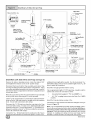
TypicalDownflowInstallation
See VentTermination
Shieldingin VentSection.
Coupling on inside
and outside of wall
to restrain vent pipe
_1
14'
InletPipe
_
(not used on
SinglePipe _
model)
_
I]
_
I,,,J I,,
'_'
*8" Min.
20' Max.
in same
atmospheric zone
Vent Pip MUST bq
support_ 4orizonte
and Vertically
Min.
Max.
same
osphericzone
•
exactly
could
ate the existing location based upon the minimum
and furnace dimensions
(Figure
3).
or wet at times.
require:
installed
at least 18" (457 ram)
protected
from pos-
may be used for construction
conditions
are met:
heat provided
that all
Failure to protect
result in property
against
damage.
the risk
of freezing
Clean outside air is provided for combustion.
This is to minimize the corrosive
effects of adhesives,
sealers and other
construction
materials.
It also prevents
drywall dust into combustion
air, which
and plugging of furnace components.
may
Special
precautions
MUST be made if installing
furnace
in an area which may drop below freezing.
This can cause improper
operation
or damage
to
equipment.
If furnace environment
has the potential
of freezing,
the drain trap and drainline
must be
protected.
The use of electric
heat tape or RV
antifreeze
is recommended
for these installations.
(See "Condensate
Trap Freeze Protection
Section")
Do
NOT
operate
furnace
in
containing
chlorine,
fluorine
chemicals.
Refer to Combustion
Contaminated
Combustion
Air.
Installation Requirements
furnace
level.
The furnace is controlled
by a thermostat.
It may not be "hot
wired" to provide heat continuously
to the structure without
thermostatic
control.
clearance
FROZEN AND BURST WATER PIPE HAZARD
Install
tile or other com-
and remedy.
If furnace is a replacement,
it is usually best to install the furnace where the old one was. Choose the location or evalu-
44001 102102
sources
Vent
The furnace is permanently
installed with all electrical wiring, piping, venting and ducting installed according
to these
installation
instructions.
A return air duct is provided, sealed
to the furnace
casing, and terminated
outside the space
containing
the furnace.
This prevents a negative
pressure
condition as created by the circulating air blower, causing a
flame rollout and/or drawing combustion
products into the
structure.
•
1.
installations
Burners and ignition
above the floor.
This furnace
the following
Refer to 3. Combustion
& Ventilation
Air section,
Contaminated
Combustion
Air for combustion
air
2,
garage
Gas
Local codes may require a drain pan under the entire furnace
and condensate
trap when the furnace is installed in attic application.
Do NOT operate furnace in a corrosive atmosphere
containing chlorine, fluorine or any other damaging
chemicals, which could shorten furnace life.
evaluation
base if the floor is damp
(See
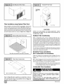
If the furnace is to be suspended
from the floor joists in a basement or a crawl space or the rafters in an attic, it is necessary
to use steel pipe straps or an angle iron frame to attach the
furnace. These straps should be attached to the furnace with
sheet metal screws and to the rafters or joists with bolts. The
preferred
method is to use an angle iron frame bolted to the
rafters or joists.
Increase minimum from 8" to 18" for cold climates (sustained temperatures
below 0°F).
25-23-33a
Failure to follow safety warnings
result in death or personal injury.
as practical.
Furnace must be located or physically
sible damage by a vehicle.
8.
CARBON MONOXIDE POISONING HAZARD.
as short
a corrosive
atmosphere
or
any
other
damaging
& Ventilation
Air section,
the entrainment
of
can cause fouling
The temperature
of the return air to the furnace
is maintained between 55 ° F (13 ° C) and 80 ° F (27 ° C), with no evening setback or shutdown.
The use of the furnace while the
structure is under construction
is deemed to be intermittent
operation
per our installation
The air temperature
instructions.
rise is within
the rated
rise range
on the
furnace rating plate, and the firing rate has been set to the
rating plate value.
The filters used to clean the circulating
air during
the
construction
process must be either changed or thoroughly
cleaned prior to occupancy.
The furnace, ductwork and filters are cleaned as necessary
to remove
drywall dust and construction
debris from all
HVAC system components
after construction
is completed.
After construction
is complete,
verify
furnace
operating
ditions including
ignition,
input rate, temperature
venting, accordinq
to these instructions.
con-
rise and
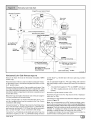
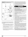
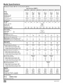
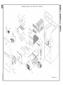
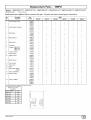
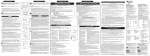
Dimensions
& Clearances
F
_O_G/AIR
INTAKE
MINIMUM CLEARANCES
TO
COMBUSTIBLE
MATERIALS FOR ALL UNITS
TOP
VEN I (*9MPD)
REAR
0
FRONT (combustion air openings in
furnace and in structure)
3"
_A_
_qE
--
Required For Service
--
LEFT SIDE
_11/4
FRONT
TRAP (KO)(COUNTERELON)_
/ ELECTRICAL
11116
VENT _
?
7 -/16
215/8
17/8
47/8
1"
NOTE: Evaporator
"A" coil drain pan dimensions
may vary from furnace duct opening
size. Always
consult evaporator
specifications
for duct size
requirements.
1913/6
_=_/
0
TOP OF FURNACE
_/4
175116
THERMOSTAT/_
(KO)
0
VENT
29_/8
24
•
1"
SIDES
Horizontal position: Line contact is permissible only between
lines formed by intersections of top and two sides of furnace
jacket, and building joists, studs or framing.
16
413116
_
TRAP (KO)
UPFLOW/HORIZONTAL
13/8
ALL SIDES Of SUPPLY PLENUM
"30" clearancerecommendedfor furnaceremoval.
131116
AIR INTAKE (KO)
(ALTERNATE)
Furnace
return,
t
Return
24
_-_
23118
ALL
DIMENSIONS
back
return
of furnace
or side
is NOT
allowed.
Boffom
28112
IN INCHES
_P
--
18112
11/16_
Capacity
GAS (KO)
N9MP1050B12
RIGHT SIDE
, TRAP (KO) (COUNTERFLOW)
N9MPlO75B12
ELECTRICAL(KO)
N9MP1080F16
N9MP1100F14
N9MPllOOJ20
air through
for bottom
/
37/8
2
Cabinet
is designed
Drawing is representative,
but some models may vary
BOTTOM
Unit
'24"
B--
AIR INTAKE(KO)
(ALTERNATE)
1:
VENT (KO)
N9MPl125J20
TRAP (KO)
UPFLOWtHORIZONTAL
N9MP2050B12
N9MP2075B12
21/4
N9MP2080F16
N9MP2100F14
9
THERMOSTAT l
N9MP2100J20
191/4
N9MP2125J20
*9MPD050F12
*9MPD075F12
*9MPDO80J16
1718
*9MPDlOOJ14
*9MPDIOOJ20
KO = KnockOut
25-23-36b
*9MPD125L20
Dentoes
E_
Brand
44001 102102
Knock Outs
level to within
and downflow
tions.
1/4" from front to back and from side to side for upflow
installations
or top to bottom for horizontal
installa-
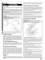
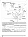
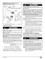
Vent and Combustion
CUT HAZARD
On the Dual Certified furnace, the vent and combustion
air pipes
attach to the furnace through the top panel for the upflow and horizontal installations.
For the downflow
installation,
the vent and
Failure to follow this caution may result in personal
injury.
Sheet metal parts may have sharp edges or burrs.
Use care and wear appropriate
clothing,
safety
glasses and gloves when handling
parts and
servicing furnaces.
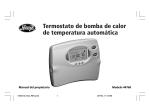
Use a hammer
and screwdriver
to strike a sharp blow (see
Figure 4) directly to the knockout tie points or use a hammer in the
upper left corner of the desired knockout.
Remove any burrs and
sharp edges.
Hammer and Screwdriver
for Knockout
Air Connections
Used
combustion
air pipes attach to the furnace
locations on the furnace side panels.
Note: On the Direct Vent furnace,
through the alternate
the vent pipe attaches
to the fur-
nace through the side panels. The combustion
air pipe attaches
the top panel or to the alternate
location on the side panel.
On the Single Pipe furnace, the vent pipe attaches
through the furnace side panels.
to
to the furnace
Note: Repositioning
of the combustion
blower is required for the
vent pipe connection
to the furnace through the "right side" panel.
See "Vent and Combustion
Air Piping"section
for further details.
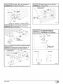
Horizontal Furnace Installation
Typical
Horizontal
Installation
Inlet Pipe (not used on Single Pipe model)
Vent
/
Condensate
Trap
25-40-06
I
OTE:
not come
after two sharp
and
snipIf a
asknockout
needed does
to remove
the out
knockout.
Installation
blows,
pull
Positions
This furnace can be installed in an upflow, horizontal
(either left or
right) or downflow
airflow position. DO NOT install this furnace on
its back. For the upflow position, the return air ductwork can be attached to either the left or right side panel and/or the bottom. For
horizontal and downflow positions, the return air ductwork must be
attached to the bottom. The return air ductwork must never be attached to the back of the furnace.
Furnace Installation Considerations
The installation
of the furnace for a given application
will dictate the
position of the furnace, the airflow, ductwork connections,
vent and
combustion
air piping. Consideration
must be given to the following:
Condensate Trap and Drain Lines
The supplied condensate
trap must be attached
to the furnace
side panel on either the left or right side. For horizontal
installations, the drain trap is vertically
attached to the side panel below
the furnace. A minimum
clearance
of 6" below the furnace is required for the condensate
trap. Downward
slope of the condensate drain line from the condensate
trap to the drain location must
be provided. Adequate
freeze protection of the drain trap and the
drain line must be provided. See "Condensate
Drain Trap"section
for further details.
Leveling
Proper leveling of the furnace must be provided to insure proper
_e
of the condensate
from the furnace. The furnace must be
44001 102102
25-23-34
NOTE: 6" bottom clearancerequiredfor condensatetrap.
This furnace can be installed horizontally
in an attic, basement,
crawl space, alcove, or suspended
from a ceiling in a basement or
utility room. See Figure 5. Do not install furnace on its back or in
the reverse airflow positions as safety control operation will be adversely affected.
If the furnace is to be installed
in a crawl space, consult
codes. A suitable concrete
pad or blocks are recommended
crawl space installation
on the ground.
NOTE:
6" bottom
clearance
required
for condensate
local
for
trap.
Twenty four (24) inches between the front of the furnace and adjacent construction
or other appliances
MUST be maintained
for service clearance.
Keep all insulating
materials clear from Iouvered
materials
may be combustible.
door.
Insulating
The horizontal
furnaces
may be installed directly on combustible
wood flooring or supports
as long as all required furnace clearances are met. See Figure 5.
This furnace MUST NOT be installed directly on carpeting or tile or
other combustible
material other than wood flooring or supports.
For horizontal
installation
over a finished
living space.
A field fabri-
cated auxiliary
drain pan with drain pipe is required to prevent
damn eq___ overflow due to blocked condensate
drain.
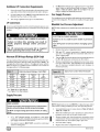
3. Combustion
& Ventilation
Air
For Single Pipe Installation
When the installation
is complete,
check that all appliances
have
adequate
combustion
air and are venting properly. See Venting
And Combustion
Air Check in "4. Gas Vent Installation"Section
in
this manual.
CARBON MONOXIDE POISONING HAZARD.
Outdoor Combustion
Failure to provide
ventilation
air could
injury.
A space
adequate
combustion
and
result in death or personal
Use methods
described
combustion and ventilation
here
air.
to
provide
with
na-
Section 8.3, Air for Combustion
and Ventilation,
of the National
Fuel Gas Code, (NFGC), ANSI Z223.1-2002/NFPA
54-2002
in the U.S.,
2.
Sections 7.2, 7.3, 7.5, 7.6, 7.7, and 7.8 of National Standard of
Canada, Natural Gas and Propane Installation Code
(NSCNGPIC), CSA B149.1-05 in Canada,
Applicable
provisions
of the local building
be vented
Air
(This
Ducts
Total input rating for all gas appliances
in the space MUST
considered
when determining
free area of openings.
2.
Connect
3.
When
MUST
4.
The minimum
ducts
or openings
screens
are used
be no smaller than
dimension
directly
be
to the outdoors.
to cover openings,
1/4" mesh.
of air ducts
MUST
the
openings
NOT be less than
Requirements
1.
Provide the space with sufficient air for proper combustion
and
ventilation
of flue gases using horizontal
or vertical ducts or
openings.
2.
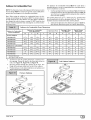
Figure 6 illustrates how to provide
air when two permanent
openings,
used.
code.
is ONLY
air for
1.
to the outside,
Outside
outdoor
When sizing a grille, louver, or screen use the free area of
opening. If free area is NOT stamped or marked on grill or louver, assume a 20% free area for wood and 60% for metal.
Screens shall have a mesh size not smaller than 1/4".
This furnace can NOT be common vented or connected
to any
type B, BW or L vent or vent connector, nor to any portion of a factory- built or masonry chimney. Multistory venting is NOT permitted.
If this furnace is replacing a previously common-vented
furnace, it
may be necessary
to resize the existing vent and chimney to prevent oversizing
problems
for the other remaining
appliance(s),
See "Venting and Combustion
Air Check"in
this section, This furnace MUST
requires
in accordance
1.
3.
in the space
Air Openings and Connecting
ings for supplying combustion
and ventilation air must comply
the gas codes, or in the absence of local codes, the applicable
tional codes.
air must be supplied
less than 50 cubic feet per 1,000 BTUH input rating
for all gas appliances
installed
combustion
and ventilation.
Furnaces
require ventilation
openings
to provide sufficient air for
proper combustion
and ventilation
of flue gases. All duct or open-
Combustion
and ventilation
with one of the following:
having
Air Method
a guide.
Subject
combustion
and ventilation
one inlet and one outlet, are
a.
One opening
MUST commence
within 12" of the floor
and the second opening MUST commence
within 12" of
the ceiling.
b.
Size openings
to codes
and ducts
per Table
having
jurisdiction.)
of country
1.
ThisinstallationNOTapprovedin Canada
GasVent
Vent
G
GableV_
Vent
_Gable
ual_ventilated
(1)
/11
Attic_
_ TopAboveInsulatio_
I/
Soffit
SoffitVent
I "etAi"l'
Vent
II
Inlet
Air(1)
Furnace
_',,
Out,o,'=
_
Air (1)
G_
_
_
_
""
Inlet
Air (2)
Inlet
Air(1)
MinimumOne Inlet and One Outlet Air Supply is Required
May be in andCombination Shown
Inlet Air Opening Must beWithin12"(300mm)of floor
Outlet Air OpeningMust be Within12"(300mm)of ceiling
(1) 1 Square Inch (6cm2) per 4000 BTUH
(2) 1 Square Inch (6cm2) per 2000 BTUH
Horizontal
duct openings
require 1 square inch of free
a rea per 2,000 BTUH (1,100 mm 2/kW) of combined input
for all gas appliances
in the space (see Table 1).
ED
d.
Vertical duct openings
or openings
directly communicating with the outdoors
require 1 square inch of free area
p e r 4,000 BTUH (550 mm 2/kW) for combined
input of all
gas appliances
in the space (see Table 1).
44001 102102
3.
When one permanent outdoor opening is used, the opening
requires:
a.
1 sq. in of free area per 3,000 BTUH (700 mm2/kW) for
combined input of all gas appliances in the space (see
Table 1) and
b.
not less than the sum of the areas of all vent connectors
in
a.
Indoor openings
tion Air Method
b.
Outdoor
openings
located as required
Combustion
Air Method above and
C.
Outdoor
the space.
of Indoor
and Outdoor
sized
2) Outdoor opening
Ratio in 1) above.
nicate with the outdoors or shall communicate
through a vertical or
horizontal
duct to the outdoors or spaces (crawl or attic) that freely
communicate
with the outdoors.
Combination
openings
with the Indoor
Combus-
in the Outdoor
as follows.
1) Calculate the Ratio of all Indoor Space volume divided by required volume for Indoor Combustion
Air Method.
The opening shall commence
within 12" of the top of the enclosure. Appliances
shall have clearances of at least 1" from the sides
and back and 6" from the front. The opening shall directly commu-
4.
that comply
below and
size reduction
Factor
is I minus the
3) Minimum
size of Outdoor openings
shall be the size
required
in Outdoor
Combustion
Air Method above
multiplied
by reduction
Factor.
Air shall have:
Area
BTUH
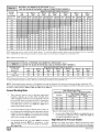
MinimumFree Area Requiredfor EachOpening or Ductto Outdoors
Input
Rating
TwoHorizontalDucts
(sq. inJ2,000 BTUH)
SingleOpening
(sq. in.i3,000BTUH)
TwoVertical Ductsor Openings
(sq. inJ4,000 BTUH)
RoundDuct
(sq. in./4,000 BTUH)
50,000
25 sq. in.
75,000
37.5 sq. in.
16.7 sq. in.
12.8sq. in.
4"
25 sq. in.
1828 sq. in.
5"
80,000
40 sq. in.
26.7 sq. in.
20.0 sq. in.
5"
100,000
80 sq. in.
33.3 sq. in.
25 sq. in.
6"
125,000
62.50sq. in.
41.7 sq. in.
31.25 sq. in.
7"
EXAMPLE:
Determining
Free Area
Furnace
Water Heater
100,000
Furnace
+
100,000
+
Total Input
30,000
Water Heater
(130,000 + 4,000)
30,000
(130,000 + 2,000)
32.5 Sq. In. Vertical
Total Input
Indoor Combustion Air
65 Sq. In. Horizontal
Standard and Known-Air-Infiltration
© NFPA& AGA
Rate Methods
Indoor air is permitted for combustion
and ventilation,
if the Standard or Known-Air-Infiltration
Rate Method is used.
The Standard
CARBON MONOXIDE POISONING HAZARD.
Failure to supply adequate combustion
result in death or personal injury.
Method
may be used, if the space
has no less vol-
ume than 50 cubic feet per 1,000 BTUH input rating for all gas appliances installed
in the space.
The standard
method
permits
indoor air to be used for combustion
and ventilation
air.
air could
Most homes will require
additional
air from
outdoors for combustion
and ventilation.
A space
with at least 50 cubic feet per 1,000 BTUH input
rating or homes with tight construction
may need
outdoor
air, supplied
through
ducts,
to
supplement air infiltration for proper combustion
and ventilation of flue gases.
The Known
filtration
Air
Infiltration
rate is known
Rate
Method
to be less than
shall be used if the in-
0.40 air changes
per hour
(ACH) and equal to or greater than 0.10 ACH.
Infiltration
rates
greater than 0.60 ACH shall not be used. The minimum
required
volume of the space varies with the number of ACH and shall be
determined
per Table 2 or Equations
1 and 2. Determine
minimum
required volume for each appliance
in the space,
add the volumes together to get the total minimum
required
the
and
vol-
ume for the space.
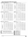
e
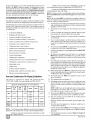
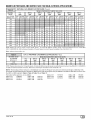
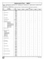
MINIMUMSPACEVOLUMEFOR100%COMBUSTION
AND VENTILATIONAIR FROMINDOORS (ft3)
Other Than Fan-Assisted Total
(1,000's Btuh)
Fan-assistedTotal
(1,OOO's
Btuh)
ACH
30
40
50
50
75
0.60
1,050
1,400
1,750
1,250
1,875
2,500
3,125
0.50
1,260
1,680
2,100
1,500
2,250
3,000
3,750
0.40
1,575
2,100
2,625
1,875
2,813
3,750
4,688
0.30
2,100
2,800
3,500
2,500
3,750
5,000
6250
0.20
3,150
4,200
5250
3,750
5,625
7,500
9,375
0.10
6,300
8,400
10,500
7,500
11,250
15,000
18,750
0.00
NP
NP
NP
NP
NP
NP
NP
NP = Not Permitted
44001 102102
100
125
Table 2 Minimum Space Volumes were determined by using the
following equations from the National Fuel Gas Code ANSI
Z223.1/NFPA 54-2002, 8.3.3.2:
1.
For other
than
hood-equipped
Volume
fan-assisted
water
other
-
appliances
such
of free area per 4,000 BTU H of total input rating for all gas appliances in the space.
In spaces that use the Indoor
Combustion
Air Method, infiltration should be adequate
to provide air for combustion,
ventilation
and dilution of flue gases. However,
in buildings
with unusually tight construction,
additional air MUST be provided using the methods described
in section titled Outdoor
Combustion
Air Method:
as a draft
heater,
21 if3
ACH
(
[ other
1000 Btu / hr
)
•
2.
For
Volume
fan-assisted
fan
appliances
15ft3
ACH
=
(
such
as this
[fan
1000 Btu I hr
Unusually
=
combined input of all other than fan-assisted
appliances in Btu/hr
[ fan = combined
input of all fan-assisted
appliances
•
apply to the Standard
Rate Method.
Method
Adjoining
rooms can be considered
part of a space,
are no closable doors between
rooms.
Doors
3.
Other openings
are caulked or sealed. These include
joints
around window
and door frames,
between
sole
plates and floors, between
wall-ceiling
joints, between
wall panels, at penetrations
for plumbing,
electrical and
gas lines, etc.
and openable
windows
and to
if there
Some provincial
spaces on the same floor level.
a free area of at least 1" 2/1,000
codes
and local municipalities
stripped
and
Combining
spaces on different floor levels. The volumes of
spaces on different floor levels shall be considered
communicating spaces if connected
by one or more permanent
openings in doors or floors having a free area of at least 2" 2/1,000
Btuh (4,400 mm2/kW)
of total input rating of all gas appliances.
An attic or crawl space may be considered
a space that freely
communicates
with the outdoors provided there are adequate
ventilation
openings directly to outdoors.
Openings MUST remain open and NOT have any means of being closed off. Ventilation openings to outdoors MUST be at least I square inch
require
ventilation
flue gases will not condense
excessively
in the heat exchanger.
Excessive condensation
will shorten the life of the heat exchanger
and possibly void your warranty.
Each opening
BTUH (2,000
mm2/kW) of the total input rating of all gas appliances
in the
space, but not less than 100 in2 (0.06 m2). Once opening
shall commence
within 12" (300 mm) of the ceiling and the
second opening shall commence
within 12" (300 mm) of the
floor. The minimum dimension of air openings shall be at least
3" (80 mm).
[_
are weather
or make-up
air be brought into the conditioned
space as replacement air. Whichever
method is used, the mixed return air temperature across the heat exchanger
MUST not fall below 60 ° so that
Venting and Combustion
Combining
shall have
with:
Ventilation Air
in Btu/hr
ACH = air changes per hour (ACH shall not exceed 0.60.)
The following
requirements
the Known
Air Infiltration
as Construction
2.
If:
[ other
is defined
Walls and ceilings exposed to the outdoors have a continuous, sealed vapor barrier. Openings are gasketed
or
sealed and
furnace,
)
tight construction
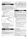
1.
Air Check
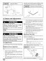
Vent Check
Vent Pipe-----_l
Typical Gas
I
f
7 Draft Hood
_'_
Wa.erHea.eL
/ i
i
Ma.c.
I
If flame
venting.
pulls
towards
I
draft
hood,
this
indicates
sufficient
NOTE: When an existing Category I furnace is removed or replaced, the original venting system may no longer be sized to properly vent the attached appliances, and to make sure there is
adequate combustion air for all appliances, MAKE THE FOLLOWING CHECK.
44001 102102
For Two Pipe Installation
CARBON MONOXIDE POISONING HAZARD
Failure to follow the steps outlined below for each
appliance connected to the venting system being
placed into operation,
could result in carbon
monoxide poisoning or death:
The following
steps shall be followed
for each
appliance
connected
to the venting
system being
placed
into operation,
while all other appliances
connected
to the venting
system
are not in
operation:
1. Seal any unused
openings
in the venting
This furnace can NOT be common vented or connected
to any
type B, BW or L vent or vent connector, nor to any portion of a factory-built or masonry chimney. If this furnace is replacing a previously common-vented
furnace,
it may be necessary
to resize the
existing vent and chimney to prevent oversizing
problems for the
other remaining
appliance(s).
See "Venting and Combustion
Air
Check"in
this section, This furnace MUST be vented to the outside.
system.
2. Inspect the venting system for proper size and horizontal
pitch, as required in the National Fuel Gas Code, ANSI
Z223,1/NFPA
54 or CSA B149, 1, Natural
Gas and
Propane Installation
Code and these instructions.
Determine that there is no blockage
or restriction,
leakage,
corrosion
and other deficiencies
which could cause an
unsafe condition.
3. As far as practical,
close all building doors and windows
and all doors between the space in which the appliance(s)
connected
to the venting system are located and other
spaces of the building.
4. Close
fireplace
dampers.
5. Turn on clothes dryers and any appliance
not connected
to the venting system. Turn on any exhaust fans, such as
range hoods
and bathroom
exhausts,
so they are
operating
at maximum
speed. Do not operate a summer
exhaust fan.
6. Followthe
inspected
appliance
lighting instructions.
Place the appliance
into operation.
Adjust
the thermostat
is operating
continuously.
being
so
7. Test for spillage from draft hood equipped
appliances
at
the draft hood relief opening after 5 minutes of main burner
operation.
Use the flame of a match or candle. (Figure
7)
8. If improper venting is observed,
during any of the above
tests,
the venting
system
must
be corrected
in
accordance
with the National
Fuel Gas Code, ANSI
Z223,1/NFPA
54 and/or CSA B149. 1, Natural Gas and
Propane
Installation
Code.
9. After it has been determined
that each appliance
connected
to the venting system
properly
vents when
tested as outlined above, return doors, windows, exhaust
fans, fireplace
appliance
dampers
and any other
to their previous
conditions
gas-fired
burning
of use.
4. Vent and Combustion
Air Piping
combustion
in absence
vent this
injury.
Use methods
described
and ventilation
air.
furnace
could
here to provide
air must comply with the gas codes
the applicable
national codes.
When the installation
is complete,
tion Air Che¢l_' in this manual.
CARBON MONOXIDE POISONING HAZARD.
Failure to properly
death or personal
and ventilation
of local codes,
result
in
combustion
Single Pipe (N91VlP1
Models)
This furnace is certified as a category [V appliance. This furnace
requires ventilation openings to provide air for proper combustion
and ventilation of flue gases. All duct or openings for supplying
44001 102102
see the" Venting
or
and Combus-
Direct Vent (N9MP2 Models)
This furnace
uses outside
is certified as a category ]V appliance.
This furnace
air for combustion
ONLY, it MUST be taken from the
same atmospheric
Space Installation
manual.
pressure zone as the vent pipe. See Confined
in the Combustion
and Ventilation
Air in this
Dual Certified (*9MPD Models)
This furnace is certified as a category ]V appliance.
This furnace
can be installed as a direct vent furnace using outside air for corn-
bustion
orthefurnace
canuseairfrominside
thestructure
forcombustion.
TheINLETairpipeisoptional.
Ifcombustion
aircomes
frominside
thestructure,
adequate
makeupairMUST
beprovided
tocompensate
foroxygen
burned.
SeeConfined Space Installation in the Combustion
and Ventilation
Air chapter. If combustion air is drawn from outside the structure,
it MUST be taken from
the same
atmospheric
pressure
zone as the vent
pipe.
Contaminated Combustion Air
Installations
in certain areas or types of structures will increase the
exposure to chemicals
or halogens
that may harm the furnace.
3) ABS to PVC transition joints REQUIRE
a special
vent cement that meets the requirements
of ASTM D3138.
cementing
procedure
to use for
NOTE: In order to create a seal that allows future removal of pipe,
RTV sealant MUST be used on the inlet pipe where it joins to the
furnace.
NOTE: All vent piping MUST be installed in compliance
with local
codes or ordinances,
these instructions,
good trade practices, and
codes of country having jurisdiction.
1.
The following areas or types of structures
may contain or have exposure to the substances
listed below. The installation
must be
evaluated
carefully
as it may be necessary
to provide outside air
for combustion.
4) Refer to ASTM D2855 for general
plastic pipe and fittings.
sol-
Determine
the best routing
and termination
and air inlet pipe by referring
guidelines
in this Section.
2.
Determine
the size required
for the vent pipe
to all of the instructions
and
for the vent pipe and air inlet
pipe.
3.
Loosely assemble all venting parts without adhesive
joint cement) for correct fit before final assembly.
4.
Furnace shall be installed
of condensate.
5.
Use of vertical
piping is preferred
because
there will be
some moisture
in the flue gases that may condense
as it
leaves the vent pipe (See Speciallnstruction
ForHorizontal
Vents).
6.
The vertical vent pipe MUST be supported
so that no weight
is allowed to rest on the combustion
blower.
7.
Exhaust vent piping or air inlet piping diameter MUST NOT
be reduced.
8.
All exhaust
vent piping from the furnace
to termination
MUST slope upwards.
A minimum of 1/4" per foot of run is
required to properly return condensate
to the furnace drain
system.
9.
Use DWV type long radius elbows whenever
possible,
as
they provide for the minimum slope on horizontal
runs and
they provide less resistance
in the vent system. If DWV elbows cannot be used, use two, 45 ° elbows when possible.
On horizontal
runs the elbows can be slightly misaligned
to
provide the correct slope.
dryers.
10.
All horizontal
pipe runs MUST be supported
at least every
five feet with galvanized
strap or other rust resistant material. NO sags or dips are permitted.
Air Piping Guidelines
11.
All vertical
pipe runs
where accessible.
12.
The minimum pipe run length is 2'.
13.
The piping can be run in the same chase or adjacent to supply or vent pipe for water supply or waste plumbing. It can
also be run in the same chase with a vent from another 90+
furnace.
•
Commercial
buildings.
•
Buildings
with
•
Furnaces
installed
in laundry
•
Furnaces
installed
in hobby
•
Furnaces
installed
near chemical
indoor
•
Permanent
wave
•
Chlorinated
waxes
•
Chlorine
•
Water
•
De-icing
•
Carbon
based
pools.
or craft rooms.
solutions
storage
areas.
for hair.
and cleaners.
swimming
softening
rooms.
pool chemicals.
chemicals.
tetrachloride.
Halogen
•
Cleaning
•
Printing
•
Hydrochloric
•
Sulfuric
Acid.
•
Solvent
cements
•
Antistatic
fabric softeners
•
Masonry
acid washing
type refrigerants.
solvents
(such as perchloroethylene).
inks, paint removers,
varnishes,
etc.
acid.
and glues.
Vent and Combustion
for clothes
materials.
This furnace is approved for venting with Schedule 40 PVC,
CPVC, ABS, Cellular Core pipe fittings and SDR-26 PVC.
Applicable
ABS
ASTM Standards for Vent
Sch. 40
SDR
Pipe
Pipe
D1527
Materials
Cell
Core
Pipe
Fittings
Primer
F628
D2468
&
D2661
--
Solv.
D1785
D2241
F891
D2466
&
D2665
F656
D2564
CPVC
F441
F442
--
F438
--
F493
..........
that are marked
be supported
every
six feet
The vent outlet MUST
be installed
atmospheric
zone as the combustion
pressure
to terminate
15.
The vent system
chimney provided
can be installed
that:
•
Both the exhaust
vent and air intake
in the same
air inlet.
in an existing
run the length
unused
of the
chimney.
D3138
NOTE:
1) In Canada, all pipe, fittings & cements must conform
applicable
CSA standards
or to local codes having jurisdiction.
2) Only use solvent cements
the specific ventinq, material.
14.
D2235
MUST
NOTE: In NO case can the piping be run in a chase where
temperatures
can exceed 140 ° F. or where radiated heat
from adjacent surfaces
would exceed 140 ° F.
Cement
PVC
ABS to
PVC
the accumulation
salts or chemicals.
•
Materials
so as to prevent
(pipe
•
No other gas fired appliance
vented into the chimney.
•
The top of the chimney MUST be sealed flush or crowned
up to seal against rain or melting snow so ONLY the piping
protrudes.
•
The termination
are maintained.
to
for use with
clearances
or fireplace
shown
in Figure
(solid
fuel)
8 & Figure
is
9
44001 102102
16. Furnace
applications
withvertical
ventsrequiring
ventdiameterincreaser
fittingsmust haveincreaser
fittings
installed
invertical
portion
ofthe vent. Condensate will be
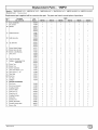
Pipe Diameter Table
N9MP2 Models
50,000
trapped in the vent if the vent diameter
is increased
prior to
having an elbow turned upward. This could cause nuisance
tripping of the pressure switch.
40' & (5) 90 ° elbows with 2" PVC pipe or
70' & (5) 90 ° elbows with 3" PVC pipe
75,000 Btuh Furnace
Combustion Air and Vent Piping Insulation
Guidelines
25' & (3) 90 ° elbows with 2" PVC pipe or
40' & (5) 90 ° elbows with 2" PVC pipe &
Long Vent Kit (See Tech. Manual) or
70' & (5) 90 ° elbows with 3" PVC pipe
NOTE: Use closed cell, neoprene insulation or equivalent.
If Fiberglass or equivalent
insulation is used it must have a vapor barrier.
Use Rvalues of 7 upto 10', R-11 if exposure exceeds 10'. If Fiberglass insulation
is used, exterior to the structure,
the pipe MUST
be boxed in and sealed against moisture.
1.
When the vent or combustion
exceeds 30", or if an exterior
zontal
MUST
2.
3.
vent to get above
be insulated.
levels,
the exterior
125,000 Btuh Furnace
40' & (5) 90 ° elbows with 3" PVC pipe
portion
Elbows
When combustion
air inlet piping is installed above a suspended ceiling, the pipe MUST be insulated
with moisture
resistant
insulation
such as Armaflex
or other equivalent
type of insulation.
If more
Insulate combustion
mid spaces.
NOTE:
shown
air inlet
Sizing Combustion
piping
when
run in warm,
hu-
Air and Vent Pipe
bows used for vent termination
outside
the structure
Pipe Diameter Table
N9MP1 & *9MPD Models
75,000
& 80,000
Btuh
Btuh
Furnaces
Btuh
are DWV Long Radius
If more than five elbows
both the inlet and exhaust
used.
reduce
the
length
5' for each additional
It is allowable
to use larger diameter
pipe and fitting
in the tables but not smaller diameters
than shown.
Kit"
Venting
of
elbow
table,
than
see
Vent Termination Clearances
CARBON MONOXIDE POISONING.
1.
Furnace
Determine termination locations based on clearances specified in following steps and as shown in Figure 8, Figure 9,
Figure 21, through Figure 29.
For "Concentric
Termination
Kit"clearances,
thru Figure 34 in "Section
5"in this manual.
Type for 2" and 3" vents.
are required,
reduce
the length
of
pipes 5' for each additional
elbow
It is allowable
to use larger diameter
pipe and fitting
in the tables but not smaller diameters
than shown.
44001 102102
pipes
Furnace
40' & (5) 90 ° elbows with 3" PVC pipe
Elbows
are required,
Inlet and outlet pipes may NOT be vented directly
above each other.
40' & (5) 90 ° elbows with 3" PVC pipe or
70' & (5) 90 ° elbows with 3" PVC pipe &
Long Vent Kit (See Tech. Manual)
125,000
elbows
and exhaust
Failure to properly vent this furnace could result in
death or personal injury.
40' & (5) 90 ° elbows with 2" PVC pipe or
70' & (5) 90 ° elbows with 3" PVC pipe
100,000
five
Type for 2" and 3" vents,
ARE counted,
including
elbows
needed to bring termination
above expected
snow levels. The elbow inside the furnace on the *9MPD IS NOT
included in the count.
50,000,
than
both the inlet
used.
are DWV Long Radius
For "Concentric
Termination
"Section
5" in this manual.
Consult Table 3 or Table 4 to select the proper diameter exhaust
and combustion
air piping. Exhaust and combustion
air piping is
sized for each furnace Btuh size based on total lineal vent length
(on inlet oroutlet
side), and number of 90 ° elbows required. Two
45 ° elbows can be substituted
for one 90 ° elbow. The elbow or el-
NOTE:
shown
100,000 Btuh Furnace
40' & (5) 90 ° elbows with 3" PVC pipe or
70' & (5) 90 ° elbows with 3" PVC pipe &
Long Vent Kit (See Tech. Manual)
air pipe height above the roof
vertical riser is used on a hori-
snow
& 80,000 Btuh Furnaces
than
see Figure
30,
2.
For Single Pipe Installation, models N9MP1 or *9MPD, refer
to Figure 9 for vent termination clearances.
3.
For Direct Vent Installation, models N9MP2 or*9MPD, refer
to Figure 8 for vent termination clearances.
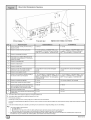
E_
ii
[_
Item
A
Clearance
AIR SUPPLY INLET
D
AREA WHERE TERMINAL
IS NOT PERMITED
Canadian Installation (1)
Description
U.S. Installation
12" (30cm)#
Clearance above grade, veranda, porch, deck, balcony, or
(2)
12" (30 cm)
anticipated snow level
B
Clearance to a window or door that may be opened
6" (15 cm) for appliances _< 10,000 BTUH (3kW), 12"
cm) for appliances
(30 kW), 36" (91 cm) for appliances
C
Clearance to a permanently
D
Vertical clearance to a ventilated soffit located above the
(30
> 10,000 Btuh (3 kW) and _<100,000 Btuh
> 100,000 Btub (30 kW)
6" (15 cm) for appliances
for appliances
_< 10,000 BTUH (3kW), 0" (23 cm)
> 10,000 Btuh (3 kW) and _<50,000 Btuh (15
kW), 12" (30 cm) for appliances
> 50,000 Btuh (15 kW)
closed window
*
terminal within a horizontal distance of 2' (61cm) from the
centedine of the terminal
E
Clearance to an unventilated
F
Clearance to an outside corner
G
Clearance to an inside comer
H
Clearance to each side of the centedine extended above
3' (91 cm) within 15' (4.5 m) above the meter/regulator
3' (91 cm) within 15' (4.5 m) above the meter/regulator
eleclrical meter or gas service regulator assembly
assembly
assembly
I
Clearance to service regulator vent outlet
3' (91 cm)
J
Clearance to non-mechanical
6" (15cm)forappliances_<10,OOOBTUH(3kW),g" (23cm)
for appliances> 10,000Btuh (3 kW) and _<100,000Btuh (30
kW) and _<50,000 Btuh (15kW), 12" (30 cm) for appliances
> 50,000 Btuh (15kW)
6" (15cm)forappliances_<10,OOOBTUH(3kW),9" (23cm)
for appliances>10,000 Btuh (3 kW)and _<50,000 Btub (15
kW), 12" (30 cm) for appliances> 50,000Btuh (15kW)
3' (91 cm) above if within 10' (3m) horizontally
the combustion
soffit
*
air supply inlet to building or
air inlet to any other appliance
K
Clearance to a mechanical air supply inlet
6' (1.83 m)
L
Clearance under a veranda, porch, deck, or balcony
12" (30 cm) +
M
Clearance to each side of the centedine extended above or
12" (30 cm)
12" (30 cm)
below vent terminal of the furnace to a dryer or water heater
vent, or other appliance's direct vent intake or exhaust.
N
Clearance from a plumbing vent stack
3' (91 cm)
3' (91 cm)
O
Clearance above a paved sidewalk or paved driveway located
7' (2.13 m)
7' (2,13 m)
on public property.
(1.)
In accordance
with the current CSA B149.1, Natural Gas and Propane
(2,)
In accordance
with the current ANSI Z223.1/NFPA
#
18" (46 cm) above roof surface
+
Permitted only if veranda, porch, deck, or balcony is fully open on a minimum of two sides benealh the floor.
For dearances
instructions.
Installation Code
54, National Fuel Gas Cede
not specified in AN SI Z223.1/N FPA 54 or C SA B149,1, clearances shall be in accordance with local installation codes and the requirements
of the gas supplier and the manufacture's
installatio
A vent shall not terminate directly above a sidewalk or paved driveway that is located between two single family dwellings and serves both dwellings.
Notes:
1,
2.
The vent for this appliance shall not terminate
a.
Over public walkways;
b.
c.
Near soffit vents or crawl space vents or other areas where condensate or vapor could create a nusiance or hazard or property damage; or
Where condensate vapor could cause damage or could be detrimental to the operation of regulators, relief valves, or other equipment.
When locating vent terminations,
Recirculation
[_
or
consideration
can cause poor combustion,
must be given to prevailing winds, location, and other conditions which may cause recirculation
inlet condensate
problems, and accelerated
of the combustiob
products of adjacent vents.
corrosion of the heat exchangers.
440O1102102
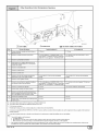
_E
"I"
[_
Item
A
1"I
VENT TERMINAL
_
AIR SUPPLY INLET
_
25-24-65-2
AREA WHERE TERMINAL
Canadian Installation (1)
Clearance Descriptions
U.S. Installation
12" (30cm)#
Clearance above grade, veranda, porch, deck, balcony, or
IS NOT PERMITED
(2)
12" (30 cm)
anticipated snow level
B
Clearance to a window or door that may be opened
6" (15 cm) for appliances _< 10,000 BTUH (3kW), 12"
cm) for appliances
(30 kW), 36" (01 cm) for appliances
C
Clearance to a permanently
closed window
D
Vertical clearance to a ventilated soffit located above the
(30
> 10,000 Btuh (3 kW) and _<100,000 Btuh
4' (1.2 m) below or to the side of the opening. 1' (30 cm)
above the opening.
> 100,000 Btub (30 kW)
*
*
terminal within a horizontal distance of 2' (61cm) from the
centedine of the terminal
E
Clearance to an unventilated
F
Clearance to an outside corner
*
G
Clearance to an inside comer
*
H
Clearance to each side of the centedine extended above
3' (01 cm) within 15' (4.5 m) above the meter/regulator
3' (91 cm) within 15' (4.fi m) above the meter/regulator
electrical meter or gas service regulator assembly
assembly
assembly
I
Clearance to service regulator vent outlet
3' (01 cm)
J
Clearance to non-mechanical
fi" (15cm)forappliances_<10,OOOBTUH(3kW),12" (30
cm) for appliances> 10,000 Btub (3 kW) and _<100,000Btuh
(30 kW), 36" (91 cm) for appliances> 100,000Btuh (30 kW)
4' (1.2 m) below or to the side of opening: 1' (30 cm) above
3' (01 cm) above if within 10' (3m) horizontally
the combustion
soffit
*
air supply inlet to building or
air inlet to any other appliance
K
Clearance to a mechanical air supply inlet
6' (1.83m)
L
Clearance under a veranda, porch, deck, or balcony
12" (30 cm) +
M
Clearance to each side of the centedine extended above or
*
opening.
below vent terminal of the furnace to a dryer or water heater
vent, or other appliance's direct vent intake or exhaust.
N
O
Clearance from a plumbing vent stack
3' (91 cm)
3' (91 cm)
Clearance above a paved sidewalk or paved driveway located
7' (2.13 m)
7' (2.13 m)
on public property.
(1.)
In accordance
with the current CSA B149.1, Natural Gas and Propane
(2.)
In accordance
with the current ANSI Z223.1/NFPA
#
18" (46 cm) above roof surface
+
Permitted only if veranda, porch, deck, or balcony is fully open on a minimum of two sides beneath the floor.
For clearances
Installation Code
fi4, Nafional Fuel Gas Code
not specified in ANSI Z223.1/NFPA 54 or CSA B149.1, clearances shall be in accordance
with local installation codes and the requirements
of the gas supplier and the manufacture's
installation instructions.
A vent shall not terminate directly above a sidewalk or paved driveway that is located between two single family dwellings and serves both dwellings.
Notes:
1.
2.
The vent for this appliance shall not terminate
a.
Over punic walkways;
b.
Near soffit vents or crawl space vents or other areas where condensate
or
c.
Wherec_ndensateva__rc_u_dcausedamage_rcou_dbedetrimentaIt_the_perafi_n_fregu_at_rs_re_iefvaIves__r_there_ui_ment_
When locating vent terminations,
Recirculafion
44001 102102
consideration
can cause poor combustion,
or vapor could create a nusiance or hazard or property damage; or
must be given to prevailing winds, location, and other conditions which may cause recirculation
inlet condensate
problems, and accelerated
of the combusfiob
products of adjacent vents.
corrosion of the heat exchangers.
E_I
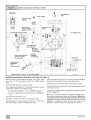
CondensateDrain Trap
This furnace removes both sensible and latent heat from the products of combustion.
Removal of the latent heat results in condensation
of the water vapor. The condensate
is removed
from the
furnace through the drains in the plastic transition
and the vent fitting. The drains connect to the externally
mounted
condensate
drain trap on the left or right side of the furnace.
The startup of a new furnace will involve a cycle or two of the furnace to properly
prime the condensate
trap with water. Until the
trap is fully primed, some condensate
will be pulled into the combustion blower. The furnace may cycle on the pressure switch connected to the plastic transition
box due to condensate
After the trap is primed, the condensate
will start draining
furnace.
densate
buildup.
from the
The combustion
blower will clear out any remaining conin the blower housing through the vent fitting downstream
FROZEN AND BURST WATER PIPE HAZARD
Failure
serious
1.
for 3/4" PVC or CPVC pipe, however alternate 1/2" CPVC (nominal
5/8" O.D.) or vinyl tubing with a minimum
inner diameter
(I.D.) of
5/8" may also be used, as allowed by local codes. Alternate
pipes and hoses may be used as allowed by local codes.
drain
The drain line must maintain a 1/4" per foot downward slope toward
the drain. 1/4" per foot is recommended.
Installation
of an overflow
line is recommended
when
the 1/4" per foot slope
sate drain cannot be maintained.
and installation
of the overflow.
See Figure
DO NOT trap the drain line in any other location
densate drain trap supplied with the furnace.
[_
to the conden-
19 for proper routing
than at the con-
pipes,
A condensate
sump pump MUST be used if required by local codes, or if no indoor floor drain is available.
The condensate
pump
condensate.
2.
must
be
approved
for
use
with
acidic
A plugged condensate
drain line or a failed condensate
pump will allow condensate
to spill. If the furnace is installed
where a condensate
spill could cause damage, it is recommended that an auxiliary safety switch be installed to prevent operation of the equipment
in the event of pump failure
or plugged drain line. If used, an auxiliary
safety switch
should be installed in the R circuit (low voltage) ONLY.
or the PVC Tee Trap.
The condensate
drain trap supplied
with the furnace
MUST be
used. The drain connection
on the condensate
drain trap is sized
water
If possible, DO NOT route the drain line where it may freeze. The
drain line must terminate
at an inside drain to prevent freezing of
the condensate
and possible property damage.
flow through the drain hose and into the condensate
drain trap.
This will prime both the vent and the transition sides of the trap. Reconnect the 1/2, ID drain hose to the original component,
either the
gutter
in burst
If a condensate
pump
is installed,
a plugged
condensate
drain or a failed pump may cause the
furnace
to shut down.
Do not leave the home
unattended
during freezing weather
without
turning
off water
supply
and
draining
water
pipes
or
otherwise
protecting
against the risk of frozen pipes.
of the blower. Note that the condensate
trap can also be primed by
pouring water into the 1/2" drain hose. Remove the1/2 " ID drain
hose from either the gutter or the white PVC Tee Trap. Using a funnel pour eight (8) ounces of water into 1/2" ID drain hose.Water
will
to do so may result
property
damage.
3.
If the auxiliary switch in the condensate
pump is used, the
furnace may shut down dueto a blocked condensate
line or
failed pump. To prevent frozen water pipes see the "Frozen
Water
Pipe Hazard"
section
on Page 4 of this manual.
Condensate Drain Trap Freeze Protection
Special precautions
MUST be made if installing furnace in an area
which may drop below freezing. This can cause improper operation or damage
to the equipment.
If the the furnace environment
has the potential of freezing, the drain trap and drain line must be
protected.
Use 3 to 6 watt per foot at 11 5 volt, 40 ° F self-regulating
shielded and waterproof
heat tape. Wrap the drain trap and drain
line with the heat tape and secure with the ties. Follow the heat
tape manufacturer's
recommendations.
44001 102102
............................
_i_!ii
= ;;;;;;;;;;;;;
===== ii; =========
=
!1
Upflow
Installations
Top
vent
On Some Models
ONLY
Single
Pressure
Switch
(Optional)
VentDrain
& Clamps
Dual
Pressure
Switch
Detail
Relief Tube
Black Rubber
Drain Tube
3/16" ID
Black Rubber
l/z" ID & Clamps
Drain Tube
Corrugate(
& Clamps
Street Elbow
1/2" CPVC
(Loose parts bag)
Drain Connector Black PVC
3/4" PVC X 1/2" CPVC
(Loose parts bag)
Casing Grommet
S/8"ID
(Looseparts bag)
Drain Line Vent Tee 3/4" PVC or
1/2" CPVC (Field supplied)
Upflow
Remove
will exit.
Install
parts
Install
Installations
Top Vent
plug from the side of the furnace
casing
grommet
(black
rubber
the 1/2" CPVC
street
elbow
parts
bag) as shown
Cut the black
fit between
Clamp
casing where Drain Tu be
5/8" ID grommet
on discharge
Trap and tube
connector
of the Drain
Tube
grommet.
clamps
Note:
cleaner
It is recommended
and fitting
connec-
before
final cementing.
Trap must
primed
Verify
all condensate
drain
before
operation.
clamped.
bag) may be installed
tem.
materials
that all PVC piping
tions be fit up and inspected
tions are securely
provided.
NOTE: "PVC" is used as a generic term. Pipe and fitting
jurisdiction.
44001 102102
from
above.
through
using
elbow to the Trap using appropriate
Connect the Tee trap and the main drain line exiting the casing as
shown Figure 19.
of Trap
(3/4" PVC x 1/2" CPVC
in the illustration
Glue the CPVC street
and solvent cement.
- in loose
Drain Tube (5/8" ID - in loose parts bag) to length to
both ends
25-24-80
(See Figure10)
bag)
Install the black PVC tube connector
loose
Drain Tube BlackRubber /8 ID & Clamps,
Cut length to fit (Loose partsbag)
A coupling
as shown
used must be acceptable
and clamps
for future servicing
be
connec-
(in loose
part
of the vent sys-
to the local code officials
having
E_
UpflowInstallationsVentthru LeftSide
Plastic Cap
Yellow or black
On Some Models
ONLY
2" PVCCoupling
Coupling & Clamps
VentDrain
& Clamps
Dual
Either: ThePVC
Drain Teeor a field
supplied2" PVC Tee
Pressure
Switch
S_lt_llchPressure
Detail
3/16"ID RubberTube
/-
Tee Trap White PVC
(loose parts bag)
Drain Tube
Black Rubber
1/2" ID & Clam
Drain Tube
DrainConnector Black PVC
3/4"PVCX 1/2" CPVC
(Looseparts bag)
Corrugated
s/8" ID & Clamps
SIDE VIEW
/_
/_5°
Casing Grommet
Black Rubber
s/8" ID
(Loose parts bag)
o
Rotatedownward
to10°
o
NOT
be angled5° to 10° also.
Drain LineVent Tee3/4" PVCor 1/2" CPVC(Fieldsupplied)
Upflow
Installations
Vent
thru
Remove
Drain Tee from
Drain Tube (1/2" ID) from
only)
inducer
bottom
Install
in side of casing.
Left
Side
25-24-81
(See Figure11)
discharge
and remove
black
of Drain Tee. (*9MPD models
Cut the black Drain Tube (5/8" ID - in loose parts bag) to length to
fit between
Clamp
Vent Pipe grommet
Cut an appropriate
length of 2" PVC pipe long enough
cabinet and connect the vent drain to either:
• A standard
field supplied
• A 2" PVC coupling
els)
2"
fastened
PVC tee (N9MP1
Tee trap into bottom
of tee.
Install
the 112" CPVC
elbow
Install the black
loose
[_
parts
PVC drain connector
bag) as shown
models),
onto the Drain Tee (*9MPD
Install
street
to exit the
or
mod-
Trap and tube connector
both ends of the Drain
Glue the CPVC street
and solvent cement.
Tube
through
using
grommet.
clamps
provided.
elbow to the Trap using appropriate
Connect the Tee trap and the main drain line exiting
shown in Figure
19.
cleaner
the casing
as
Note: It is recommended
that all PVC piping and fitting connections be fit up and inspected
before final cementing.
Both the internal Trap and the external
Tee Trap must be primed
before
on discharge
of Trap
(3/4" PVC x 1/2" CPVC
in the illustration
above.
from
operation.
clamped.
installed
Verify all condensate
drain connections
are securely
A coupling
and clamps
(in loose part bag) may be
as shown
for future
servicing
of the vent system.
44001 102102
All Models Vent thru Right Side
Plastic Cap
Yellow or black
_On
Some Models
ONLY
Relief Tube
Black Rubber
"ID
/
VentDrain
& Clamps
Either:The PVC
DrainTee or a field
"_ingle Pressure
Switch
Detail
DrainTube
Corrugated
sis"
"Barbed Coupling,
1/2"
OD
Drain Line Vent Tee 3/4"PVC
CPVC(Field supplied)
SIDE VIEW
_otate
Drain Connector Black PVC
3/4"PVC X llz" CPVC
(Loose parts bag)
downward
Grommet
"Black RubberS_" CPVC
(Looseparts bag)
25-24-82
NOTE.T
Built-inchannelwill
be angled 5° to10° also.
All
Models
Disconnect
Vent
the black
thru
Right
Drain Tube
Side
between
(See Figure 12)
the drain vent and the
Trap.
Install
parts
Rotate the inducer
inducer attachment
screws
180 ° for a right side vent after loosening the 4
screws.
Reinstall and retighten
the inducer
to 20" pounds
torque.
Install
grommet
(black
rubber
the 1/2" CPVC
street
elbow
5/8" ID grommet
on discharge
Install the black PVC tube connector
loose
Using
casing
- in loose
bag)
parts
bag) as shown
of Trap
3 ,
( /4' PVC x 1/2" CPVC
in the illustration
from
above
the 1/2" OD barbed coupling in the loose parts bag connect
1 ,
together with the 2 short /2' ID elbowtubes
and connect the lower
discharge
port of the vent drain to the Trap. Secure all connections
Cut the black Drain Tube (5/8" ID - in loose parts bag) to length to
fit between Trap and tube connector
through grommet.
with clamps.
Clamp both ends of the Drain Tube using clamps provided.
Install
the vent pipe grommet
into the casing
Cut an appropriate
length of 2" PVC pipe long enough
cabinet and connect the vent drain to either:
•
A standard
•
A 2" PVC coupling
models)
Install
field
supplied
Tee Trap into bottom
Remove
will exit.
2"
fastened
section
PVC tee (_9MP1
onto the
models),
or
Tee (_9MPD
of Tee.
plug from the side of the furnace
44001 102102
Drain
to exit the
casing where Drain Tube
Glue the CPVC street
and solvent cement.
elbow to the Trap using appropriate
Connect the Tee trap and the main drain line exiting
shown in Figure
19.
Note:
It is recommended
that all PVC piping
cleaner
the casing
and fitting
connec-
tions be fit up and inspected
before final cementing.
Both
ternal Trap and the external
Tee Trap must be primed
operation.
clamped.
installed
as
the inbefore
Verify all condensate
drain connections
are securely
A coupling
and clamps
(in loose part bag) may be
as shown
for future
servicing
of the vent system.
Downflow
Left
Side
Vent
and
Trap
SIDE VIEW
Yellow or black Plastic
Cap
//'_
Rotate downward
2" PVCCoupling
Coupling& Clamps
(Optional)_
NOTE_. Bruit-in channel will
he angled 5° to 10° also.
DrainTube
Black Rubber
1/2" ID & Clamps
VentDrain
& Clamps
Either: The PVC
Drain Tee or a field
Dual
Pressure
Switch
supplied 2" PVCTee
/
ReliefTube
Black Rubber
3/16"ID
On Some Models
Tee Trap White PVC
(looseparts bag)
ONL¥
INLET
_
<_
Elbow Tube
112" ID & Clam
(Loose Parts Bag)
Single
Pressure
Switch
/
Flexible Tubing Connector,
3/16" OD (loose parts bag)
ReliefTube Extension
Black Rubber,
3/16"ID Cut to fit
-- (looseparts bag)
Detail
trap
TrapConnection
to top of
DrainTube Corrugated 5/8" ID
Cut at straight section
I
BarbedCoupling 1/2" OD
',LooseParts Bag)
Leave roo_
Downflow
Remove
Left
the
and retighten
inducer
Side
Vent
mounting
the inducer
screws
cover plate and gasket provided
hole from the burner compartment
secure with screws.
and Trap
Cut the 5/8" ID corrugated
screws,
rotate
the inducer
to 20" pounds
180 °
torque.
in the loose parts bag, cover the
to the blower compartment
and
hose as shown
bend end to the Trap and fasten
drain. Secure both connections
the 1/2" ID drain
Connect
hose from the vent drain to the Trap
with clamps
the 3/16" ID relief tube from the small
the to.p_port of the transition
as shown
additional
port on the Trap to
in the.picture.
In some cases,
hose length will be needed.
Use the clear plastic 3/16"
3
,
length of extra /16' ID
OD flexible tubing connector
and a suitable
hose to make this connection.
Install
the vent pipe grommet
into the casing
Cut an appropriate
length of 2" PVC pipe long,
cabinet and connect the vent drain to either:
•
•
above and fasten the 90 °
the straight end to the transition
with clamps.
and secure with a clamp.. In some cases, additional
length will be
required for this hose. Use the Black plastic 1/2" OD barbed coupling and a suitable section of 1/2" ID hose to make the connection.
all connections
25-24-83
(SeeFigure 13)
Move the caps to the top of the Trap and mount the Trap externally
to the left side of the unit using the 2 screws provided.
Secure
&
insert into furnace
Cut Here
Disconnect
the hoses from the Trap assembly,
and remove Trap
and Trap mounting bracket from the blower compartment.
Using
Reconnect
Preassemble
to exit the
A standard field supplied 2" PVC tee (N9MP1), or
A 2" PVC coupling fastened onto the Drain Tee (*9MPD
models)
Install
Tee Trap into bottom
Connect
shown
Note:
enough
section
of Tee.
the Tee trap and the main drain line exiting
in Figure
the casing
It is recommended
that all PVC piping
and
fitting
connec-
tions be fit up and inspected
before final cementing.
Both
ternal Trap and the external
Tee Trap must be primed
operation.
clamped.
installed
as
19.
the exbefore
Verify all condensate
drain connections
are securely
A coupling
and clamps
(in loose part bag) may be
as shown
for future
servicinq
of the vent s_ystem.
44001 102102
Downflow
Right Side Vent and Trap
Plastic Cap
Yellow or black
Trap Connection
"Clamp ears"
ointed OUT
_otate
downward
& Clamps
Relief
Black
Elbow Tube BlackRubber
1/2" ID & Clamps
(Loose Parts
Vent Drain
Barbed Coupling
1/2" OD
(Loose Parts Bag)
NOTE_. Built-in channel will
Pressure
Switch
Detail
Dual
Pressure
3/16" ID
DrainTube
Black Rubber
112"ID
Cut to Fit &
be angled 5° to 10° also.
Single
Preassemble &
insert into furnace
Tube
Rubber
Coupling & Clamps
Switch
On Some
Models ONLY
2" PVCCoupling
Either:The PVC
supplied 2" PVC Tee
TeeTrap White PVC
Drain TubeCorrugateds/8"ID & Clamps
WARNING
Move Caps to top of trap
/
/
DrainConnector Black _-
©
PVC3/4"PVC X 112"CPVC
(Looseparts bag)
DrainTube Black Rubber,
5/8" ID Cut to fit & Clamps
(loose parts bag)
25-24-83a
Downflow
Remove
Right
the Drain
Disconnect
Side
Vent and
Trap
(See Figure 14)
Tee if installed.
the hoses
Install
from the Trap assembly,
and remove
Trap
and Trap mounting bracket from the blower compartment.
Using
cover plate and gasket provided in the loose parts bag, cover the
hole from the burner compartment
secure with screws.
to the blower
compartment
and
Move the caps to the top of the Trap and mount the Trap externally
to the right side of the unit using the 2 screws provided.
Connect
the corrugated
Drain
Tube from the transition
Connect
the drain
Secure
all connections
with clamps.
hose from the Vent Drain to the Trap.
into the casing
Cut an appropriate
length of 2" PVC pipe long,
cabinet and connect the vent drain to either:
•
A standard
•
A 2" PVC coupling
models)
Install
field
supplied
Tee Trap into bottom
enough
2" PVC tee (N9MP1
fastened
section
onto
the Drain
to exit the
models),
or
Tee (*9MPD
of Tee.
box to the
Trap as shown. If an extension is required, use the black PVC tube
connector and the black 5/8" ID Drain Tube in the loose parts bag.
Cut tube to length.
the vent pipe grommet
If an ex-
Connect the Tee trap and the main drain line exiting
shown in Figure
19.
the casing
as
Note:
It is recommended
that all PVC piping and fitting connections be fit up and inspected
before final cementing.
Both the ex-
tension is required, use the black 1/2" OD barbed coupling, connect a black 1/2" ID elbow tube and a suitable section of a 1/2" ID
ternal Trap and the external
Tee Trap must be primed
before
operation.
Verify all condensate
drain connections
are securely
drain tube to make connection
from the vent drain
cure all connections
with clamps.
clamped.
installed
44001 102102
to the trap. Se-
A coupling
and clamps
(in loose part bag) may
as shown for future servicing
of the vent system.
[_
be
Horizontal
Vent Drain
& Clamps
Left Thru Top
Single
Plastic Caps
black
Pressure
Switch
Detail
Trap Connection
Pointed OUT
/"Clamp
Alternate
ears"
Orienation
Preassemble &
insert into furnace
Relief Tube
Black Rubber
Dual
Pressure
/3/16"
Switch
ID
j
Flexible TubingConnector
;"OD (Loose PartsBag)
Relief TubeExtension
"ID
Cut tp Fit (LooseParts Bag)
Field
Drain Tube
Black Rubber
Coupling & Clamps
(Optional)
Supplied Tee
Drain TubeCorrugated /8 ID & Clamps
Cut at straight section
I
Cap andClamp
Open End
Tee Trap White PVC
(loose parts bag)
Leaveroomfor clamp
Cut Here
25-24-84
Horizontal
Disconnect
Left-Thru
the hoses
Top
(See Figure15)
from the Trap assembly,
and remove
Trap
and Trap mounting bracket from the blower compartment.
Using
cover plate and gasket provided in the loose parts bag, cover the
hole from the burner compartment
secure with screws.
Mount
the Trap externally
2 screws
provided
Cut the corrugated
nect the corrugated
connections
compartment
and
shown.
the black
the black
1/2" ID Drain
from the Drain Tee.
over the open drain
1/2" ID Drain
connections
Tube
Tube
Install
port of the Drain Tee.
from the Vent Drain
to the
with clamps.
Connect the 3/16" ID relief tube to the middle port on the Trap. If an
extension
is required,
use the 3116" OD flexible tubing connector
[_1
Secure
all connections
•
A standard
•
A 2" PVC coupling
models)
field
supplied
Cut tube
with clamps.
Cut an appropriate
length of 2" PVC pipe, long enough
cabinet and connect the vent drain to either:
Install
2" PVC tee (N9MP1
fastened
Tee Trap into bottom
Connect
with clamps.
cap and clamp
to length.
to exit the
models),
or
side of the unit using the
tube as shown in the illustration
above. Conhose from the transition
to the Trap. Secure
a yellow
Trap. Secure
to the bottom
in the location
Remove
Connect
to the blower
and the black 3/16" ID relief tube in the loose parts bag.
section
onto
the Drain
of Tee.
the Tee trap and the main drain line exiting
shown
in Figure
Note:
It is recommended
Tee (*9MPD
the casing
that all PVC piping
and fitting
connec-
tions be fit up and inspected
before final cementing.
Both
ternal Trap and the external
Tee Trap must be primed
operation.
clamped.
installed
as
19.
the exbefore
Verify all condensate
drain connections
are securely
A coupling
and clamps
(in loose part bag) may be
as shown
for future
servicing
of the vent system.
440O1102102
Horizontal
Left-Side
Vent
Single Pressure
Alternate
Switch
Detail
Orienation
£
Yellow or black
Plastic
Field
'_
Level
or Sloped
Dual
towards
Pressure
3/16"
Tee
VentDrain
& Clamps
Switch
ID
Elbow Tube Black Rubber
ID & Clamps
(Loose Parts Bag)
f
TeeTrap White PVC
(looseparts bag)
BarbedCoupling
1/2" OD (LooseParts Bag)
r
\
OnSome_--_
Drain TubeBlack Rubber
112"ID & Clamps
_
Models ONLY
jo
WARNING
Flexible Tubing
3/16" OD (Loose Parts Bag)
Drain TubeBlack, 5 /A_r ID Corrugated
Cut at stra!igl_tsection
Relief Tube Extension
Black Rubber 3/16" ID Cut to Fit
(Loose Parts Bag)
_Cut
Leaveroom for clamp
Here
25-24-88
Horizontal
Remove
the
models
only)
Left-Side
Drain
(See Figure 16)
Tee from the Vent
Drain
if installed
(*9MPD
and the black 3/16" ID relief tube in the loose
180 ° for a side vent after loosening
screws.
torque.
Reinstall
and retighten
the 4 induc-
the inducer
screws
Disconnect
the hoses from the Trap assembly,
and remove Trap
and Trap mounting
bracket from the blower compartment.
Using
cover plate and gasket provided in the loose parts bag, cover the
hole from the burner compartment
secure with screws.
to the blower
compartment
and
Cut an appropriate
length of 2" PVC pipe, fittings and extension
pipe long enough to exit the cabinet and connect the vent drain to
either:
•
A standard
•
A 2" PVC coupling
models)
Install
Mount the Trap externally
to the bottom side of the unit using the
2 screws provided
in the location shown.
wards
tube as shown
nect the corrugated
hose
connections
with clamps.
in the illustration
from the transition
above.
Con-
Note:
and the black 1/2" ID Drain
Cut tube to length.
Secure
Tube in the loose
connections
parts
with clamps.
Connect the 3/16" ID relief tube to the middle port on the Trap. If an
extension
is required,
use the 3/16"OD flexible tubing connector
44001 102102
2" PVC tee (N9MP1
fastened
section
onto
the Drain
models),
or
Tee (*9MPD
of Tee.
The pipe to the Tee Trap must be level or sloping
to-
the Tee trap and the main drain line exiting
in Figure
the casing
as
19.
to the Trap. Secure
Connect the black 1/2" ID Drain Tube from the Vent Drain to the
Trap. If an extension
is required, use the black 1/2" OD flexible tubbag.
shown
supplied
the Tee Trap
Connect
Cut the corrugated
field
Tee Trap into bottom
Important:
ing connector
parts bag. Cut tube
to length.
Rotate the inducer
er attachment
to 20" pounds
Vent
It is recommended
that all PVC piping
and
fitting
tions be fit up and inspected
before final cementing.
Both
ternal Trap and the external
Tee Trap must be primed
operation.
clamped.
connecthe exbefore
Verify all condensate
drain connections
are securely
A coupling
and clamps
(in loose part bag) may be
installed as shown for future servicing
of the vent system.
A coupling
and clamps (in loose part bag) may be installed
shown
for future
servicing
of the vent system.
[_J
as
Horizontal
Right thru Top
Single
Trap Connection
Pressure
Switch
Detail
Alternate
Orienation
Plastic Cap
Yellowor black
Coupling & Clamps
Preassemble&
insertintofurnace
i
WARNING
Field
Vent Drain
& Clamps
Add Cap and
Clamp
\
Supplied Tee
_Tee
\
\
Relief Tube Rubber Tube
3/16" ID
Trap
_"
White PVC
oose parts bag)
FlexibleTubing Connector
3/16"OD (LooseParts Bag)-_.__
112"
ID & Clamps(LoosePartsBag)
ReliefTube Extension
Black Rubber 3/16" ID
Cut to Fit (Loose Parts Bag)
,.LET
On SomeModels
ONLY
\
/
,
(Loose PartsBag)
Drain Tube Black Rubber
112"ID & Clamps
Drain Tube Corrugated s/8"ID & Clam
Cut at strai_ section I
Leave roomfor cla/mp"
Horizontal
Disconnect
Right
the hoses
25-24-89
"_'" Cut Here
Thru Top (SeeFigure17)
from the Trap assembly,
and remove
Trap
nector
and the black 3/16" ID relief tube in the loose parts bag.
and Trap mounting
bracket from the blower compartment.
Using
cover plate and gasket provided in the loose parts bag, cover the
tube to length,
hole from the burner compartment
secure with screws.
Cut an appropriate
Mount
the Trap externally
2 screws
provided
Cut the corrugated
nect the corrugated
connections
to the blower
to the bottom
in the location
compartment
and
side of the unit using the
shown.
and the black 1/2" ID Drain
Cut tube to length.
Connect
[_
Secure
Tube
connections
in the loose
is required,
parts
bag.
with clamps.
the 3/16" ID relief tube to the middle
an extension
Tee Trap into bottom
Connect
shown
with clamps.
port on the Trap. If
use the clear 3/16" OD flexible
tubing con-
length
of 2"
PVC pipe, fittings
pipe long enough to exit the cabinet and connect
a standard
field supplied
2" PVC Tee
Install
tube as shown in the illustration
above. Conhose from the transition
to the Trap. Secure
Connect the black 1/2" ID Drain Tube from the Vent Drain to the
Trap. If an extension
is required, use the black 1/2" OD barbed
coupling
BarbedCoupling 112"OD
section
and extension
the vent drain to
of Tee.
the Tee trap and the main drain line exiting
in Figure
Cut
the casing
as
19.
Note:
It is recommended
that all PVC piping and fitting connections be fit up and inspected
before final cementing.
Both the external Trap and the external
Tee Trap must be primed
before
operation.
Verify all condensate
drain connections
are securely
clamped.
installed
A coupling
and clamps
(in loose part bag) may
as shown for future servicing
of the vent system.
be
440O1102102
HorizontalRight-SideVent
Plastic Cap
Yellow or black
Coupling & Clamps
ptional)
Vent Drain
& Clamps
Single
Pressure
Switch
Field
Detail
j
Supplied Tee
/
Level or Sloped
towards Tee
J'/
Tee Trap
_
White PVC
(Iooseparts bag)
/
ReliefTube BlackRubber
/
Elbow Tube
Black Rubber
112"ID & Clamps
(Loose Parts Bag)
3/16"ID
On Some Models
FlexibleTubingConnector
3/16"OD (Loose Parts Bag)
ONLY
INLET
<_
Relief Tube Extension_
Alternate
Black Rubber 3/16" ID
Cut to Fit (Loose Parts Bag)
Dual Pressure
Switch/_
Drain TubeCorrugated, s/8" ID & Clamps/
(
Cut at straight section
Leaveroom for clamp
Horizontal
Disconnect
Right
Side
Drain Tee if installed
connections
(*9MPD
models
only)
in the loose parts bag, cover the
to the blower compartment
and
tube as shown in the illustration
above. Conhose from the transition
to the Trap. Secure
with clamps.
Connect the black 1/2" ID Drain
Trap. If an extension
is required,
Tube from the Vent Drain to the
use the 1/2" OD barbed coupling
and the black 1/2" ID Drain Tube in the loose
to length. Secure connections
with clamps.
parts bag. Cut tube
Connect the 3/16" ID relief tube to the middle port on the Trap. If
an extension
is required, use the clear 3/16"OD splice connector
and the black 3/16" ID relief tube in the loose
to length.
44001 102102
Coupling
1/2" OD
(LooseParts Bag)
25-24-84c
Vent (See Figure 18)
Mount the Trap externally
to the bottom side of the unit using the
2 screws provided
in the location shown.
Cut the corrugated
nect the corrugated
Drain Tube
BlackRubber
1/2" ID & Clamps
Cut Here
Disconnect
the hoses from the Trap assembly,
and remove Trap
and Trap mounting bracket from the blower compartment.
Using
cover plate and gasket provided
hole from the burner compartment
secure with screws.
Orienation
parts bag. Cut tube
Cut an appropriate
pipe long enough
either:
length
of 2" PVC pipe, fittings and extension
to exit the cabinet
and connect
the vent drain to
•
A standard field supplied 2" PVC tee (N9MP1 models), or
•
A 2" PVC coupling
models)
Install Tee Trap into bottom
fastened onto the Drain Tee (*9MPD
section
of Tee.
Important: The pipe to the Tee Trap must be level or sloping towards the Tee Trap
Connect the Tee trap and the main drain line exiting
shown in Figure
19.
Note:
It is recommended
that all PVC piping
and
the casing
fitting
tions be fit up and inspected
before final cementing.
Both
ternal Trap and the external
Tee Trap must be primed
as
connecthe exbefore
operation.
Verify all condensate
drain connections
are securely
clamped.
A coupling
and clamps
(in loose part bag) may be
installed as shown for future servicing
of the vent system.
[_
iiiiiiiiiiiiiiiiiiiiiiiiiiii!
¸I¸!
!!ii¸!;::
i¸I¸I
¸I;I
¸!!i!i!!!i
¸i¸iJiii ii!!iil ii ¸iiiiiiiiiiiiii
Connecting
Trap and
Tee Trap
Main Drain
to Condensate
Line
Important:
Prime both traps with water before operation.
Failure to prime the traps may result in discharge
of flue gases
from the condensate
drain line and open tee for a period of
time, and may result in temporary
lockout of the furnace upon
start up. Main drain line construction
is left to the discretion
of
the installer. It may be made of either ridged
pipe or flexible
tube. Tube ID should NOT be less than 1/2%
Connecting
Vent and Combustion
Air Piping
CARBON MONOXIDE POISONING HAZARD
Failure to properly seal vent piping could result in
death or personal injury.
Open Tee
\,
Cement or mechanically seal all joints, fittings,
to prevent leakage of flue gases.
etc.
Refer to Figure 10 through
Figure 18 that corresponds
installation
position of the furnace for the application.
Preassemble
the vent and combustion
to the vent termination.
Do not cement
preassembly
Evaporator
Coil
Drain Line
process
Install the air intake
four(4) screws.
and gasket
to the furnace
or
with the
25-24-85
right side panels. Install the 3" hole plug from the furnace accessory bag and relocate to the open hole in the furnace panel. Use four
screws to seal the four(4) mounting
holes in the top panel next to
the hole plug. Drill four(4) 7/64" diameter holes in the casing using
the air intake coupling
as the template.
The air intake
The Tee Trap must be connected
to the main condensate
drain
line as conceptually
shown above. Different
installations
may
require slightly different orientations.
The following
steps apply
to all installations.
The Tee Trap should be installed as close to the side or top
of the furnace as practical. Minimize the distance between
the inducer and the Tee Trap as much as possible.
An open tee is to be used at the Tee Trap discharge.
The top
end of the tee should be open to the atmosphere
nate potential
air lock problems.
to elimi-
4.
The drain line from
furnace condensate
the Tee Trap is to be connected
to the
trap drain line as shown above.
5.
Condensate
drain lines from a cooling coil may be connected downstream
of the connection
point of the Tee Trap
and Furnace Condensate
Trap.
coupling
is sized
for 2" PVC pipe.
Install the combustion
air pipe to the air intake coupling
sealant to provide for future serviceability.
using
RTV
Vent Pipe Connection
Install the vent pipe grommet
to the furnace
panel. Locate the
grommet in the furnace panel at a location directly away from the
vent fitting on the combustion
blower. The grommet snaps into the
3" hole from the furnace panel. NOTE: Depending
on the installation position, the vent pipe grommet will be installed to the top panel or to the alternate location on the side panels. If needed, remove
the 3" hole plug from the loose parts bag and install in the open
hole in the furnace panel. (See Figure 10 or Figure 19)
Install the vent pipe to the rubber coupling,
the vent fitting or the
PVC vent extension pipe. Securely attach using the clamp or PVC
cement as required.
Note:
[_
coupling
(Dual Certified
For downflow installation,
the air intake coupling and gasket must
be installed to the alternate air intake location on either the left or
Condensate
Trap
3.
is complete.
Note: The air intake cou piing and gasket ca n be installed to the top
panel to the alternate
air intake locations on either the left or right
side panels of the furnace.
Main
Drain
Line
2.
air piping from the furnace
the pipe joints until the pipe
Combustion Air Pipe Connection
Direct Vent)
(Optional)
to the
The
vent
fitting
MUST
be installed
with
the
air
flow
marking
arrow pointed
toward the vent pipe. (See Figure 20)
Some installations
require the vent fitting to be installed
with
a 5 ° to 10 ° downward
slope. (See Figure
10 thru Figure 19)
44001 102102
Proper Sealing Procedure
Combustion
Blower
RubberCoupling
_Vent
& Clamps___
_
furnace. PVC, CPVC, ABS, and Cellular Core pipe and cement
may be used on all other joints.
for
Pipe
VentPiDe _
r
CARBON MONOXIDE POISONING HAZARD
_([op
Panel Exit)
N °TE:
The 90 ° elbow
for use inside
is approved
the furnace
ONLY.
90° Elbow
& Clamps
Combustion
Blower
Failure to follow this warning could result in death or
personal injury.
Do NOT use solvent cement that has become
curdled,
lumpy or thickened
and do NOT thin.
Observe precautions
printed on containers.
For
applications below 32 ° F., use only low temperature
type solvent cement.
Poor joints
may lead to
disconnected
or leaking vent pipe joints allowing
carbon monoxide to enter the living space.
1.
pipe
end
square,
remove
ragged
Chamfer end of pipe, then clean fitting,
of all dirt, grease, or moisture.
Pipe (Side Panel
Exit)
SIDE VIEW
edges
and
burrs.
socket and pipe joint
NOTE: Stir the solvent cement frequently
while using. Use a natural bristle brush or the dauber supplied with the cement. The proper brush size is one inch.
Tee
2.
After checking
pipe and socket for proper fit, wipe socket
and pipe with cleaner-primer.
Apply a liberal coat of primer
to inside surface of socket and outside of pipe. Do NOT allow primer to dry before applying cement.
3.
Apply a thin coat of cement evenly in the socket. Quickly apply a heavy coat of cement to the pipe end and insert pipe
into fittings with a slight twisting movement
until it bottoms
out.
wnward
NOTE: Built-in channel will beangled 5° to 10° also.
25-24-14a
Joining Pipe and Fittings
NOTE:
pipe.
FIRE HAZARD
Failure to do so could cause death, personal
and/or property damage.
Observe all cautions
material containers
Cut
and warnings
Provide adequate
ventilation
near heat source
or open
while using solvent cements
skin or e_es.
injury
printed
Cement
MUST
be fluid while
inserting
pipe. If NOT, recoat
4.
Hold the pipe in the fitting for 30 seconds to prevent the tapered socket from pushing the pipe out of the fitting.
5.
Wipe
all excess
cement
from the joint
with a rag. Allow
minutes before handling.
Cure time varies
temperature
and humidity.
on
according
15
to fit,
Connecting Vent Pipes and Termination
and do NOT assemble
flame.
Do NOT smoke
and avoid contact with
NOTE:
Combustion
air intake
and vent
MUST
terminate
in the
same atmospheric
pressure zone. If installation
is in a cold climate
(sustained
temperatures
below 0°F), increase
the minimum
distance between vent pipe and air intake from 8" to 18".
This furnace is approved for venting with Schedule 40 PVC,
CPVC, ABS, Cellular Core pipe fittings and SDR-26 PVC.
NOTE: All PVC, CPVC, ABS, and Cellular Core pipe fittings, solvent cement, primers and procedures MUST conform to American
National Standard Institute and American Society for Testing and
Materials (ANSI/ASTM) standards.
Pipe and Fittings:
PVC - Ref ASTM D1785, D2241, D2466,
D2665 & D3311
ABS - ASTM D2661, D1527 & F-628
Cellular Core - F-891
•
PVC Primer and 5olvent Cement - Ref ASTM D2564
•
Procedure for Cementing Joints - Ref ASTM D2855
•
Procedure for PVC to AB5 transition - Ref ASTM D3138
NOTE: In order to create a seal that allows future removal of pipe,
RTV sealant MUST be used on the inlet pipe where itjoins to the
44001 102102
CARBON MONOXIDE POISONING HAZARD.
Failure to properly vent this furnace could result
in death or personal injury.
Maintain a minimum of 36" between combustion
air inlet and clothes dryer vent. Terminate the
combustion air intake as far as possible from any
air conditioner,
heat pump, swimming
pool,
swimming pool pumping, chlorinator or filtration
unit.
Install all couplings, nipples and elbows using proper procedures for Joining
Pipe and Fittings
and maintain spacing
between
vent and combustion
air piping as indicated
in
Figure 21 through Figure 29.
[_
SidewallTermination
More
.............................................................................
AboveSnowLevel
or 12"or
GradeLevel
MIN.
_
"18" Minimum
Vertical Termination
1.
Figure
vertical
for cold climates
23 shows the proper installation
and clearances
for
vent termination.
The vertical
roof termination
should be sealed with a plumbing
roof boot or equivalent
flashing. The inlet of the intake pipe and end of the exhaust
vent must be terminated
no less than 12" above the roof or
snow accumulation
or other protrusion.
2.
(substained
below
on the inlet air to provide
necessary
clearance.
0 ° F)
Rooftop
EL
wall
If the vent system is installed in an existing chimney make
sure clearances
shown in Figure 23 are maintained.
Horizontal section
before the termination
elbow can be extended
1
level, and 12" away from a vertical
Termination
25-00-05F
SNOW LEVEL
Horizontal Termination
1,
Cut two holes. 21/2" for 2" pipe, 3" for 21/2" pipe, or 31/2" for
3" pipe. Do NOT make the holes oversized, or it will be necessary to add a sheet metal or plywood plate on the outside
with the correct size hole in it.
2.
Check hole sizes by making sure it is smaller than the couplings or elbows that will be installed on the outside. The
couplings
or elbows MUST prevent
the pipe from being
pushed back through the wall.
3.
Extend vent pipe and combustion
3/4" to 1" and seal area between
4.
Install the couplings,
nipple and termination
elbows as
shown and maintain spacing between vent and combustion
air piping as indicated
in Figure 21 and Figure 22.
A metal shield
is recommended
air pipe through
pipe and wall.
the wall
18" x 18" min. or 18" min. diameter
a round the vent termination
at the exterior wall to protect the house
exterior
materials
from flue product
or condensation
(freezing)
damage.
Using ExteriorRisers
1.
Install elbows
in Figure
22.
2.
Secure vent pipe to wall with galvanized
strap or other
resistant
material to restrain pipe from moving.
rust
3.
Insulate pipe with Armaflex
closed cell foam insulation
in and sealed
and pipe to form riser as shown
against
or equivalent
or Fiberglass
moisture
insulation
resistant
if boxed
moisture.
Sidewall Termination with Exterior
Risers
Grade
to Get
Level
Above
Snow
Level
or
A = 12" Aboveroofor snowaccumulation
level
B= 8" Min.,20'Maximum,
exceptin areaswithextremecoldtemperatures
(sustained
below0°% the18" Min.
Vent Termination Shielding
Under certain wind conditions some building materials may be affected by flue products expelled in close proximity to unprotected
surfaces.
Sealing or shielding of the exposed surfaces with a corrosion resistant material (such as aluminum
sheeting) may be required to prevent staining or deterioration.
The protective
material
should be attached and sealed (if necessary)
to the building before
attaching
the vent terminal.
Multi Vent Termination Clearances
When two (2) or more furnaces
furnace
must be individually
are vented
near each other, each
vented.
Two (2) vent terminations
may be installed
Figure 25, Figure 26, Figure 27, Figure
as shown in Figure 24,
28 and Figure 29, but
the next vent termination
must be at least 36" away from first 2 terminations.
It is important that vent terminations
be made as shown
to avoid recirculation
of flue gases.
8" *
MIN.
20'
"18" Minimum
for cold climates
(substained below 0° F)
g_ii_
I Air
c°ncentric
Roof Termination
Vent and c°mbusti°n-
8"
MIN.
J
12" Min. Grade or_
Snow Level
Combustion
Air
25-00-04F
Dimension "A"is touching or 2"maximumseparation.
44001 102102
Concentric Vent and CombustionAir Sidewall Termination
Rooftop Inlet Vent and ExhaustAir Termination
18" Min. for Cold Climates
(SustainedBelow 0° F)
F
\
_
8" Min.
20' Max.
/
12" Min.
Exhaust
Level
Exhaust
25-22-02d
Dimension
"A" is touching
or 2" maximum
25-22-43
separation.
1 Exhaust-Air
Sidewall
Termination
Inlet Vent and
iii_i_:
¸!!!!_!:!;ii
¸ii
¸ii
¸fill
¸11;%;!;
¸i!i!i!i!i!i!i!i!i!i!i!i%i;i;iiii
¸ii;;!!%iiiiiiiiiiiiiiiiiiiiiil;;!;!;!:!_i
¸
Recommended
Alternate
Installation
for Sustained
.............................................................................
Cold Weather (-O ° F & below)
_
OVERHANG
8" Min.
EXHAU_ k 12_ MIN.
18" Min.
for
Cold
Climates
(Sustained Below 0o F)
INLET
12" Min. Grade or
Snow Level
__Dimension
"A" is touchin_
Sidewall
Inlet Vent
Termination
///
or 2" maximum
separation.
and Exhaust-Air
with Exterior
Risers
Ground
Level
f 12" MIN.
OR Snow
Level
_
18" Min. for Cold Climates
(Sustained Below 0° F)
8" Min.
FRONT
VIEW
Gradeor
Snow Level
SIDE VIEW
12"
Same Joist
Space
25-23-73
Dimension "A" is touchinq or 2" maximum separation.
44001 102102
[_
5. Concentric
Termination
Vent Termination Clearances
Vertical & Horizontal Termination
1,
CARBON MONOXIDE
EXPLOSION HAZARD
POISONING,
2.
FIRE AND
Inlet and outlet pipes may NOT be vented directly
above each other (standard vent terminals).
Determine
2.
cified
in following
steps
and as shown
in Figure 8,
Figure 30 through Figure 35.
The vent termination
must be located at least 12" above
ground
3.
4.
5.
termination
or normally
locations
expected
snow
on clearances
accumulation
5 or Table
Determine
the
best
required
6 and Figure
location
for the installation
32.
for the termination
kit. See
vapors to plants/shrubs,
other equipment
and building materials, 2) possible damage to the terminal from foreign objects, 3) wind effects that may cause recirculation
of flue
products,
debris or light snow and 4) visible vent vapor•
spe-
Concentric
Vent
Roof
Installation
levels.
Do NOT terminate
over public walkways.
Avoid areas
where condensate
may cause problems
such as above
planters, patios, or adjacent to windows where steam may
cause fogging.
Vent
Maintain12" min.clearance
above
highest
anticipated
snowlevel.Max.
_24"
Combustion
The vent termination
shall be located at least 4' horizontally
from any electric meter, gas meter, gas regulator, and any
relief equipment.
These
distances
apply ONLY to U.S.
installations.
aboveroof.
R°°f2i'r°"
Flashing
_..
r
(FieldSupplied)
The vent termination
is to be located at least 3' above any
forced air inlet located within 10'; and at least 10' from a
combustion
air intake of another
direct vent furnace intake.
6.
based
the pipe diameters
from Table
Figure 31 for vertical termination
or Figure 35 for horizontal termination•
Roof termination
is preferred
since it is less
susceptible
to damage,
has reduced intake contaminants
and less visible vent vapor• For side wall termination,
consideration
should be given to: 1) possible damage from the
Failure to properly vent this furnace could result in
death, personal injury and/or property damage.
1.
Determine
appliance,
except
In Canada, the Canadian
FuelGas
Codetakes
over the preceding termination
instructions.
(FieldSupplied)
another
45° Elbow
precedence
Concentric Vent Termination - Kit #
NAHA001CV & NAHA002CV
These
kits are for vertical
or horizontal
tion air inlet and the exhaust
termination
of the combus-
vent pipes on Category
Combustion
i
[V gas-fired
condensing
furnaces.
The NAHA001CV
kit can be used for 3" diameter pipe systems. The NAHA002CV
kit can be used for 2" diameter pipe system. Refer to Table 5 or Table 6 for the correct
pipe size for the furnace. Both the combustion
air inlet and the exhaust vent pipes must attach to the termination
kit. The termination
kit must terminate
outside the structure
and must be installed per
the instructions
outlined below for vertical or horizontal
termination. Vertical termination
is preferred.
Field supplied
tings are required to complete
the installation.
Vent _
pipe and fit-
25-22-02
Note:
Support
3.
must be field installed
Cut one 5" diameter
NAHAOOICV
Kit or
NAHAOO2CV
4.
to secure termination
hole
one
kit to structure•
through
the
4" diameter
structure
hole
for the
for the
Kit.
Dimension D may be lengthened to 60" max. or shortened
by cutting the pipes to 12" min. Dimension A will change according to D dimension. (See Figure 32)
Kit Components
KitContents:
3" Rain Cap or 2" Rain Cap
3 Diameter SDR-26 Pipe, 19 /2 Long or
.
1 .
4 Diameter SDR-26 Pipe, 37 /8 Long,
2t_ Diameter SDR-26 Pipe, 315 /8i_ Long or
21/2"Diameter SDR-26 Pipe, 24" Long,
3" Y Concentric Fittingor 2" Y Concentric Fitting
Nominal3" or4" Dia.
,/.
AlL
SDR-26Pipe
2" or 3" Dia.
•
YConcentricFitting
2 or 2112" Dia.
Rain Cap
SDR-26Pipe
25-22-03
[_
44001 102102
Concentric
ConcentricVentDimensional
Termination
Kit
NAHAOOICV & NAHAOO2CV Venting
Table for NDMP2 Models
Drawing
50,000
& 80,000 Btuh Furnaces
NAHAOO2CV - 35' & (4) 90 ° elbows with 2" PVC pipe or
NAHAOOICV - 65' & (4) 90 ° elbows with 3" PVC pipe
75,000 Btuh Furnace
NAHAOO2CV
NAHAOO2CV
Long Vent Kit
NAHAOOICV
11/2"
PVC
,ntake,C, s 0
._
125,000 Btuh Furnace
Model
A*
B
C
D _*
NAHAOO1CV
381/8
3
41/2
211/8
33_/8
2
31/2
16;/8
NAHAOOICV
- 35' & (4) 90 ° elbows with 3" PVC pipe
1. Do not include the field supplied 45 ° elbow in the total elbow
count,
2. If more than four elbows are required, reduce the length of
both the inlet and the exhaust pipes five feet for each
additional elbow used.
3. Elbows are DWV long radius type for 2" and 3" vents,
will change accordingly
as dimension
D is
or shortened.
D may be lengthened
to 60" may also be
by cutting the pipes provided
in the kit to 12"
NOTE: Feet of pipe is whichever
inlet or outlet side,
Concentric
Termination
NAHA001CV
for
*9MPD
pipe run is the longest,
either
If assembly needs to be extended to meet height or side wall thickness requirement,
the two pipes supplied
in the kit may be replaced by using the same diameter
solid, single (no coupling
connections)
field supplied
SDR-26
PVC (ASTM D2241) pipes.
Do not extend dimension
D more than 60". (See Figure
32)
Kit
Venting
& NAHA002CV
Table
Models
50,000, 75,000 & 80,000 Btuh Furnaces
NAHA002CV
NAHA001CV
90 ° elbows with 2" PVC pipe or
90 ° elbows with 2" PVC pipe &
Manual) or
90 ° elbows with 3" PVC pipe
100,000 Btuh Furnace
25-22-03
* = Dimension
lengthened
** = Dimension
shortened
minimum
& (2)
& (4)
Tech.
& (4)
NAHAOOICV - 35' & (4) 90 ° elbows with 3" PVC pipe or
NAHAOOICV - 65' & (4) 90 ° elbows with 3" PVC pipe &
Long Vent Kit (See Tech. Manual)
A
NAHAOO2CV
- 20'
- 35'
(See
- 65'
Do not use field supplied
couplings
to extend
the pipes.
Airflow
restriction
will occur and the furnace
pressure
switch
may cause intermittent
operation.
- 35' & (4) 90 ° elbows with 2" PVC pipe or
- 65' & (4) 90 ° elbows with 3" PVC pipe
100,000 Btuh Furnace
Rain Cap to Vent Pipe Assembly
NAHA001CV - 35' & (4) 90 ° elbows with 3" PVC pipe or
NAHA001CV - 65' & (4) 90 ° elbows with 3" PVC pipe &
Long Vent Kit (See Tech. Manual)
Drill clearance hole in rain
125,000 Btuh Furnace
NAHA001CV
- 35' & (4) 90 ° elbows
1, Do not include
count,
the field
with
supplied
3" PVC
45 ° elbow
2, If more than four elbows
are required,
both the inlet and the exhaust
pipes
additional
elbow
used,
3, Elbows
are DWV
NOTE: Feet of pipe
inlet or outlet
side.
long
radius
type
is whichever
pipe
pipe
capandp_t
in the
total
reduce
the length
five feet for each
of
Stainless
25-22-02
for 2" and
run
pipe.
elbow
steel screw
(Fieldsupplied)
3" vents.
is the
longest,
either
CARBON MONOXIDE POISONING HAZARD
5.
Partially
Clean
assemble
and cement
the
concentric
vent
termination
the parts using the procedures
kit.
for Join-
ing Pipe and Fittings
section
of the manual.
A) Cement
theY
Concentric
to
4"
kit
(See
Figure
fitting
33) B) Cement
kit part. (See Figure
steel screw
44001 102102
diameter
(See Figure
pipe.
the 3" rain cap to the 21/2" diameter
33) NOTE:
A field supplied
may be used to secure
instead of cementing
cleaning
the
when
33)
stainless
the rain cap to the pipe
field disassembly
is desired
for
Failure to follow this warning
or personal injury.
could result in death
When using the alternate screw assembly method,
drill a clearance hole in the rain cap and a pilot hole
in the vent pipe for the screw size being used.
Failure to drill adequate holes may cause cracking
of the PVC components, allowing flue gases to be
recirculated.
E_
Concentric Vent and CombustionAir Side Termination
CARBON MONOXIDE POISONING HAZARD
Failure to follow this warning
or personal injury.
could result in death
Roof Overhang
Do not operate the furnace with the rain cap
removed as recirulation
of the flue gases may
occur. Water may also collect inside the larger
combustion
air pipe and flow to the burner
enclosure.
6,
Install the Y concentric
fitting and the pipe assembly through
the structure's
hole. For vertical termination,
install the parts
through the field supplied roof boot/flashing.
NOTE: Do not
allow insulation or other materials
to accumulate
inside the
pipe assembly
7.
when
installing
through
the structure's
Maintain12" clearanceabove highestanticipatedsnow level or gradewhichever is greater.
25-22-02
hole.
Secure the assembly tothe structure as shown in Figure 31
or Figure 35 using field supplied metal strapping or equivalent material.
Concentric
Attachment
NOTE: Ensure the termination
height is above the roof surface or anticipated
snow level as shown in Figure 31 for
vertical termination.
Ensure the termination
location clearance dimensions
are as shown
for horizontal
termination.
8,
9.
10.
in Figure
34 and Figure
35
Strap
(Field Supplied)
Install the rain cap and the small diameter pipe assembly in
the Y concentric
fitting and the large pipe assembly. Ensure
that the small diameter
pipe is bottomed
out and securely
cemented
in the Y concentric
fitting.
Cement the furnace combustion
air and vent pipes
concentric
vent termination
assembly.
See Figure
Figure 35 for proper pipe attachment.
CARBON MONOXIDE
EXPLOSION HAZARD.
Y///_
Combustion
Vent
S
to the
34 or
Operate the furnace through one heat cycle to ensure combustion air and vent pipes are properly connected
to the
concentric
termination
connections.
6. Gas Supply
Vent Sidewall
,
1" max.
Combustion
Air
45° Elbow
(FieldSupplied)
_-:_c_-:
......
25-22-02
Note:
Securing
strap must be field installed to prevent
movement of termination kit in side wall.
and Piping
POISONING,
FIRE
1.
Properly size gas pipe to handle combined
appliance
load
or run gas pipe directly from gas meter or LP gas regulator.
Refer to NFGC and ANSI Z223.1 for proper gas pipe size.
2.
Install
3.
Measure
regulator.
AND
Failure to follow these instructions
could result in
death, personal injury and/or property damage.
NOTE:
Models designated for Natural Gas are to be used
with Natural Gas ONLY, unless properly converted to
use with LP gas.
NOTE: The rating plate is stamped with the model number, gas
type and gas input rating. In addition,
models manufactured
for
sale in Canada have orifice size information
stamped on the rating
plate.
Gas Piping Requirements
NOTE: The gas supply line must be installed bya qualified
technician
in accordance
with all building codes.
service
correct
pipe size for run length
pipe length
In the state
from gas meter
and furnace
or LP second
rating.
stage
of Massachusetts:
1.
Gas supply connectors
plumber or gas fitter.
2.
When flexible connectors
are used,
shall not exceed 36" (915 mm).
3.
When lever handle type manual equipment
are used, they shall be T-handle
valves.
4.
The use of copper tubing for gas piping
the state of Massachusetts.
NOTE: Refer to Figure
the furnace.
The rules
installations.
MUST
be performed
by a licensed
the maximum
length
shut off valves
is NOT approved
by
36 or Figure 37 for the general layout at
listed apply to natural and LP gas pipe
NOTE: On the Dual Certified or Direct Vent models, install the gas
pipe grommet to the furnace side panel with the gas pipe entry. If
needed, remove the 2" hole plug and relocate to the open hole in
the furnace
side .panel.
44001 102102
Use black iron or steel pipe and fittings or other pipe approved by local code.
FIRE OR EXPLOSION HAZARD
Failure
to properly
install
metal
could
result
in death,
personal
property
damage.
6.
Use ground joint unions and install a drip leg no less than 3"
long to trap dirt and moisture before it can enter gas valve.
7.
Use two pipe wrenches when making connections
vent gas valve from turning•
to pre-
Install
casing
gas connector
injury
and/or
A flexible
corrugated
metal gas connector
must be
properly
installed,
shall not extend through
the side
of the furnace,and
shall not be used inside
the
furnace.
a manual
and tighten
Black iron pipe shall be installed at the furnace gas
control valve and extend a minimum of 2" outside
furnace casing.
shut-off
all joints
valve
external
If local codes
allow the use of flexible
tors, always
use a new, listed connector•
nector
which
appliance•
to furnace
securely•
has
previously
gas appliance
connec-
Do not use a con-
serviced
another
iiiiiiii_i!!i!i!i!i!i!::_i;:;:;:il;i:::::i
¸_i_!_i_i!_iii_i_ii_i!i!i!iiii_iii!iiiiiiiiiiiii_ii_iii!!_iiiiiiiiiiiiiiiiii_iiiii_iiiiiiiiiiiiiiiiiiiiiiii_i;i_i!i;i_ii_ii_ii_ii_ii_ii_ii_
Typical Gas Pipingfor
Upflow
Drip Leg and Union, Union * should be outside the
Gas Pipe Grommet (Single Pipe)
cabinet•Manual shut-off valveMUST be upstreamof
dripleg,
union,
and furnace.
vM_;eUa,
shut-off
_
/
"--......_
Use elbows and 3" pipenipple to connectvalveto
piping when using rightside gas pipeentry, _
_
_
_
_,_
_
__
_
_._
_._
_
_
_,
_
•Alterative
installation
'n_P_,Pe
_
_
_
.._
hMOdee
_ may
or2
re
4 :L, s.,c
8S
25-24-86
bUcn_o nem:fYcf:a
irn Stcaellse.dinside
the ca binet
when
n ecessa
ry
_
"_d
_
iiiiiiiiiiiiiiiiiiiiT!i!ii
pica,
Gas
i ! Piping
i for
i iD
i iownf,ow
i i i i i i i i i i i iiii:ii
Use elbows
and 3" pipe nipple to connect
valve
to piping when using left side gas pipe entry.
LP Low pressure
switch REQUIRED.
Drip Leg and Union,
the cabinet.
Manual
upstream
_Union may be installed
because
of clearances.
44001 102102
inside
the
cabinet
of dripleg,
when
Union*
shut-off
union,
necessary
Manualshutvalve
should
valve
MUST
be
and furnace.
Gas Pipe Grommet
(Single Pipe)
25-25-46a
gas
Do NOT allow minimum gas supply pressure to vary downward. Doing so will decrease input to furnace. Refer to
Table 7, Table 8, Table 9, Table 10 and Table 11 for normal gas supply and manifold pressures.
Additional LP Connection Requirements
1.
Have a licensed LP gas dealer make all connections
at storage tank and check all connections
from tank to furnace.
2.
If copper
National
3.
Two-stage
tubing is used, it MUST complywith
Fuel Gas Code or CGA codes.
regulation
limitation
Gas Supply Pressure
set in
Gas supply pressure should be within minimum and maximum values listed on rating plate. Pressures are usually set by gas suppliers.
of LP gas is recommended.
LP Conversion
Manifold Gas Pressure Adjustment
An accessory
kit shall be used to convert to propane gas use, see
the furnace rating plate for the LP conversion
accessory
kit part
number.
NOTE: Make adjustment to manifold pressure with burners operating.
ELECTRICAL
FIRE, EXPLOSION,
Failure
death,
injury.
to follow
property
UNIT DAMAGE
HAZARD.
this warning can result
damage
and/or
personal
Failure to do so could
injury.
in
Alternate BTUH Input Ratings(USA Only)
The input rating of these furnaces can be changed from the standard input rating to the alternate input rating shown in Table 7, by
the burner
Remove
2.
With gas OFF, connect
gas valve. See Figure
water column range.
3.
Turn gas ON. Operate
the R to W thermostat
4.
Remove manifold pressure adjustment
screw cover on furnace gas control valve. Turn adjusting screw counterclockwise to decrease
manifold
pressure
and clockwise
to
increase
iiiiiiiiiiiiil;;i;
¸i¸i
iil ¸i!!!;;;
iiiiiiil;;iiiiiii!i!
!!!!!ii!iil
BTUH
Alternate
Rating
Natural
Gas
Orifice*
LP
Gas
Orifice**
50,000
40,000
#44
#55
75,000
60,000
#44
#55
100,000
80,000
#44
#55
125,000
100,000
#44
#55
door.
manometer
to tapped opening on
38. Use manometer
with a 0 to 15"
the furnace by using a jumper
connections
on the control.
!;
Typical
Gas
Regulator Adjustment
Under Ca
Control
Valve
HONEYWELL
©o
* See Table 10 for High Altitude.
** See Table 11 for High Altitude
wire on
pressure.
Input Ratings, USA ONLY.
BTUH
Standard
Rating
compartment
speed
1,
changing
the main burner orifices.
Changing
of burner orifices
MUST be done by a qualified service technician.
See section on
changing
orifices or following
page.
I
result in death or personal
Turn OFF power to furnace before changing
taps.
An LP conversion
accessory
kit is required
when operating
the furnace with LP gas.
Alternate
SHOCK HAZARD.
Honeywell
b
Outlet
Pressure
Tap
1/8NPT
/
OUTLET
Inlet
Pressure
Tap 1/8NPT
Supply Pressure
25-24-98a
FIRE HAZARD
NOTE: Adjustment screw cover MUST be replaced on gas control
valve before reading manifold pressure and operating furnace.
Failure to properly set input pressure could result in
death, personal injury and/or property damage.
Do NOT set input rating above that shown on rating
plate.
1,
2,
[_1
A 1/8" NPT plugged tapping, accessible
connection,
must be installed immediately
gas supply connection
to the furnace.
Gas input to burners MUST
shown on rating plate.
NOT exceed
for a test gauge
upstream
of the
the rated
input
II
5.
Set manifold
pressure to value
Table 10 or Table 11.
6.
When the manifold pressure is properly set, replace
justment
screw cover on the gas control valve.
7.
Remove jumper
wire from thermostat
connection
on the
control board. Remove manometer
connection
from man-
I
ifold pressure
8.
Check
9.
Replace
tap, and replace
for leaks
shown
in Table
8, Table
9,
the ad-
plug in gas valve.
at plug.
the burner
compartment
door.
44001 102102
MANIFOLDPRESSUREAND ORIFICE SIZE FOR HIGHALTITUDEAPPLICATIONS
iiiiiiiiiiiiiiiiil
iiiii
NATURAL GAS MANIFOLD PRESSURE (" w.c.)
..............................................................
HEATING
VALUE
at ALTITUDE
BTU/CU. FT.
MEAN ELEVATION
0 to
2000
Orifice
No.
2001 to
3000
Manifold
Pressure
Orifice
No.
FEET ABOVE
3001 to
4000
Manifold
Pressure
Orifice
No.
SEA LEVEL
4001 to
5000
Manifold
Pressure
Orifice
No.
5001 to
6000
Manifold
Pressure
Orifice
No.
Manifold
Pressure
6001 to
7000
7001 to
8000
Orifice
No.
Manifold
Pressure
41
3.7
725
41
3.7
41
3.4
750
41
3.5
42
3.6
700
775
800
Manifold
Pressure
41
3.6
42
3.6
42
3.3
41
3.6
42
3,7
42
3,4
42
3.1
825
41
3.7
41
3.4
42
3.5
42
3.2
42
2.9
850
41
3.5
42
3.6
42
3,3
42
3,0
42
2.8
875
41
3.6
42
3,6
42
3.4
42
3,1
42
2,8
42
2.6
900
42
3.7
42
3.4
42
3.2
42
2,9
42
2.7
42
2.5
925
41
3.7
42
3,5
42
3,3
42
3.0
42
2,8
42
2,5
44
3.3
950
41
3.5
42
3.3
42
3.1
42
2.9
42
2.6
42
2.4
44
3.1
975
42
3.7
42
3,2
42
2,9
42
2.7
42
2.5
44
3.2
45
3.6
1000
42
3.5
42
3.0
42
2.8
42
2.6
42
2.4
45
3.7
45
3.4
1050
42
3.2
42
2,7
42
2.5
44
3.3
45
3.6
1100
43
3.6
42
2,5
44
3.2
45
3.6
_!%
_i_i_i_i_i_i_i_i_i_i_i_i_i_!_i_i_i_i_i_i_i_i_i_i_i_i_i_
_i_i_i_i_i_i_i_i_i_i_i_!%:;i
i_i_i_i_i_i_i_i_i_i_i_i_i¸_¸_;_¸i¸_%i_¸i_¸i_¸i_
iiiiiiiiiiiiiiiiii!_i_i_i!ii!ii!ii!ii!ii!ii!ii!ii!i!ii!
iiiiiiiiiiiiiiiiiiiiiiiiiiii!_i_i_i!ii!ii
NOTE: Natural gas data is based on 0.60 specific gravity.
For fuels with different specific gravity consult the National
Z223.1-2002/NFPA
54-2002 or National Standard of Canada, Natural Gas And Propane Installation Code CSA B149.1-05.
Bold-
Orifice
No.
Fuel Gas Code ANSI
indicates factory orifice size.
iiiiiiiiiiiiiiiiiiiiiiiiiiiiiiiiiiiiiiiiiiiiiiiiiiiiiiiiiiiiiiiiiiiiiiiii
: i!i ! ! (" !w.c.)! i
LPG or PROPANE GAS MANIFOLD iPRESSURE
MEAN ELEVATION
i i i i i i i i i i i i i
HEATING VALUE
at ALTITUDE
BTU/CU. FT.
0 to
2001 to
3001 to
4001 to
FEET ABOVE SEA LEVEL
5001 to
6001 to
7001 to
2000
3000
4000
5000
6000
7000
8000
2500
10.0
10.0
9.0
10.0
9.4
8.5
10.0
Orifice Size
#54
#54
#54
#55
#55
#55
#56
NOTE: Propane data is based on 1.53 specific gravity. For fuels with different specific gravity consult the National Fuel Gas Code ANSI Z223.1-2002/N
54-2002
FPA
or National Standard Of Canada, Natural Gas And Propane Installation Code CSA B149.1-05.
NOTE: The derating
of these furnaces
at 2% (Natural Gas) and 4% (Propane
In Canada, the input rating must be derated 5% (Natural Gas) and 10% (Propane
the 2001 to 3000 column in Table 8, Table 9, Table 10 and Table 11.
The burner orifice part nos. are as follows:
Orifice #41
1096942
Orifice
Orifice #43
1011377
Orifice
Orifice #45
1011353
Orifice
44001 102102
#42
#44
#46
1011351
1011352
1011744
Orifice
Orifice
Orifice
Gas) has been tested and design-certified
by CSA.
Gas) for altitudes of 2,000 to 4,500 above sea level. Use
#47
#49
#55
1011378
1113202
1011354
Orifice
Orifice
Orifice
#48
#54
#56
1113201
1011376
1011355
E_
NATURAL GAS MANIFOLD PRESSURE (" w.c.)
FOR THE 80,000 BTUH MODEL AND ALTERNATE
MEAN ELEVATION
HEATING
VALUE
0 to
2000
at ALTITUDE
BTU/CU.
Orifice
No.
FT,
2001 to
3000
Manifold
Pressure
Orifice
No.
3001 to
4000
Manifold
Pressure
Orifice
No.
INPUT MODELS
FEET ABOVE SEA LEVEL
4001 to
5000
Manifold
Pressure
Orifice
No.
5001 to
6000
Manifold
Pressure
Orifice
No.
6001 to
7001 to
7000
Manifold
Pressure
8000
Orifice
No.
Manifold
Pressure
Orifice
No.
Manifold
Pressure
725
44
3.7
44
3,7
44
750
44
3,4
3.5
44
3.2
700
775
800
44
3,5
44
3.2
44
3,0
44
3.6
44
3.3
44
3.0
44
2.8
825
44
3,7
44
3.4
44
3,1
44
2.9
44
2,6
850
44
3.5
44
3.2
44
2.9
44
2.7
44
2.5
875
44
3,5
44
3,3
44
3.0
44
2.8
44
2.5
47
3.4
900
44
3,3
44
3,1
44
2.8
44
2,6
44
2.4
48
3.6
925
44
3.7
44
3.2
44
2,9
44
2.7
44
2,5
48
3.7
48
3.4
950
44
3,5
44
3,0
44
2,8
44
2.6
44
2,4
48
3.5
48
3.3
975
44
3.3
44
2.8
44
2,6
44
2.4
48
3.7
48
3.4
49
3.6
1000
44
3,2
44
2,7
44
2,5
47
3.3
48
3.5
48
3.2
49
3.4
1050
44
2.9
44
2.5
48
3.7
48
3.4
49
3.7
1100
46
3.3
45
3.7
48
3.4
49
3.7
NOTE: Natural gas data is based on 0.60 specific gravity.
For fuels with different specific gravity consult the National
Z223.1-2002/NFPA
54-2002 or National Standard of Canada, Natural Gas And Propane Installation Code CSA B149.1-05.
Bold-
indicates
factory
orifice
Fuel Gas Code ANSI
size.
LPG or PROPANE GAS MANIFOLD PRESSURE (" w.c.)
................................................................................................................
FOR THE 80,000 BTUH MODEL AND ALTERNATE INPUT MODELS
HEATING VALUE
MEAN ELEVATION
at ALTITUDE
BTU/CU, FT.
0 to
2000
2500
10.0
Orifice Size
#55
2001 to
3000
FEET ABOVE SEA LEVEL
3001 to
4000
4001 to
5000
5001 to
6000
6001 to
7000
7001 to
8000
8.9
8.4
10.0
10.0
10.0
10.0
#55
#55
#56
#56
#56
#56
NOTE: Propane data is based on 1.53 specific gravity. For fuels with different specific gravity consult the National Fuel Gas Code ANSI Z223.1-2002/N
54-2002 or National Standard Of Canada, Natural Gas And Propane Installation Code CSA B149.1-05.
NOTE:
The derating
of these
furnaces
at 2% (Natural
Gas) and 4% (Propane
o
Gas) has been tested
In Canada, the input rating must be derated 5% (Natural Gas) and 10 _ (Propane
the 2001 to 3000 column in Table 8, Table 9, Table 10 and Table 11.
Gas) for altitudes
General Derating Rules
Nameplate
1.
These
installed
may
at altitudes
be used
at full
up to 2,000'.
input
When
Elevation
High
Natural
above
Altitude
[USA]
Multiplier
Gas
LP Gas
0.95
0.90
3001'-4000'
0.93
0.86
input rating must be derated
each 1000' above sea level.
4001'-5000'
0.91
0.82
5001'-6000'
0.89
0.78
6001'-7000'
0.87
0.74
7001'-8000'
0.85
0.70
high altitude
For operation
required
input rate.
with natural
and/or
5% (natural) or 10% (LP) for
See Table 10 or Table 11 for
gas at altitudes
manifold
for the gas supplied.
pressure
above 2,000',
adjustments
First consult
supplier, then refer to Table 8 for required
and/or orifice change for high altitudes.
[_
when
High Altitude
Input Rate =
Sea Level Input Rate x (Multiplier)
2001'-3000'
fice change
3,
rating
installed
by CSA.
of 2,000 to 4,500 above sea level. Use
2,000', the input must be decreased
2% (natural) or 4% (LP)
for each 1000' above sea level in the USA. In Canada, the
required
2,
furnaces
and design-certified
your
pressure
ori-
may be
local gas
change
For operation with LP gas, gas orifices MUST be changed
and manifold pressure MUST be maintained
as per
Table 9. Orifices can be ordered through our distributor.
(See Fi.gure 39)
* Based
4.
on mid-range
FPA
of elevation.
In cases where Table 8 or Table 9 is not applicable,
eg. alternate input rate application,
refer to Table 10 or Table 11
for required high altitude input rate.
High Altitude Air Pressure Switch
Altitudes
over 4,000'
may require
a different
air pressure
than the one installed at the factory. Check parts
switch and consult [/our distributor for.part number
switch
list for pressure
and availability.:
44001 102102
InCanada,
provincial
codesmaygoverninstallation
ofswitch.
Check
withgoverning
authorities.
2.
Turn OFF gas supply
to all appliances
and start
furnace.
Example
Changing Orifices for High Altitude
BTU Content
Per Hour
Foot in Seconds
Hour
1,000
3,600
48
75,000
.oturo,0as
t .oo'Seconds
t 'ime
Per
Cubic
t "*°Per
ELECTRICAL
HAZARD
SHOCK,
FIRE
OR
1,O0O x 3,600 + 48 = 75,000 BTUH
EXPLOSION
Failure to properly install orifices could result in
death, personal injury and/or property damage.
Turn OFF electric power (at disconnect)
and gas
supply (at manual valve in gas line) when installing
orifices. Installation of orifices requires a qualified
service technician.
3.
Time how many seconds it takes the smallest dial on the gas
meter to make one complete
revolution.
Refer to Example.
4.
Relight
NOTE:
two.
all appliances
and ensure
all pilots
If meter uses a 2 cubic foot dial, divide results
are operating.
(seconds)
by
Final Check
NOTE: Main burner orifices can be changed for high altitudes.
1.
2.
Disconnect gas line from gas valve.
Remove manifold from furnace.
3.
Remove the orifices from the manifold and replace them
with properly sized orifices.
4.
Tighten orifices
Figure 39)
5.
Reinstall manifold. Ensure burners do NOT bind on new orifices.
so it is seated
Changing
FIRE OR EXPLOSION HAZARD
and gas
tight.
(See
Orifices
Measure from face of orifice
to the back side of the
manifold.
11/8 " to 13/16"
Failure to follow the safety warnings exactly could
result in death, personal injury, and/or property
damage.
Never test for gas leaks with an open flame. Use a
commercially
available soap solution made specifically for the detection
of leaks to check all
connections.
A fire or explosion
could result
causing property damage, personal injury and/or
loss of life.
1. The furnace and the equipment
shut off valve must be disconnected from the gas supply piping system during any pressure testing of that system at test pressures
in excess of 1/2"
PSIG. Close the manual shut-off
valve before testing at
such pressures.
2.
2
3. The furnace must be isolated from the gas supply system by
closing the equipment
shut off valve during any pressure
testing of thegas supply system
less than 1/2' PSI (3.5 pa).
Natural Gas Input Rating Check
NOTE: The gas meter can be used to measure input to furnace.
Rating is based on a natural gas BTU content of 1,000 BTU's per
cubic meter. Check with gas supplier for actual BTU content.
1.
Make sure burner compartment door is in place before performing the following steps.
7. Electrical
When installation
is complete,
test all pipe connections
for
1 ,
leaks with the gas pressure
less than /2' PSIG to the gas
valve.
4,
Apply
leaks.
5.
Correct
6.
Check
burner
at test pressure
equal to or
a commercial
soap solution to all joints
Correct any leaks indicated
by bubbles.
to test for
even the smallest
leak
at once.
for leaks at gas valve and orifice connections
manifold while the furnace is operating.
to the
Wiring
Power SupplyWiring
ELECTRICALSHOCK
HAZARD.
Failure to turn off power could
personal injury.
result in death or
Turn OFF electrical power at fuse box or service
panel before making any electrical connections
and ensure a proper ground connection
is made
before connecting line voltage.
The furnace MUST be electrically
wired and grounded
in accordance with local codes, or in the absence of local codes with the
latest edition of The National Electric Code, ANSI N FPA 70 and/or
The Canadian
Electric Code CSA C22.1.
The power
to the furnace
connections
furnace
must be between
operation
for acceptable
Field wiring connections
must be made inside the furnace connection box. A suitable strain relief should be used at the point the
wires exit the furnace casing.
Copper
conform
44001 102102
supply
104 VAC and 127 VAC during
performance.
conductors
shall be used. Line voltage wires should
to temperature
limitation of 63 ° F (35 ° C) rise and be sized
forthe
unit maximum
amps stated
on the rating
plate. Add the full
load amps for potential
field-installed
accessories
such as electronic air cleaners
and humidifiers
that would receive power from
the furnace control. The furnace control is rated for a maximum
of
1.0 amps
codes
combined
for proper
for EAC
and
wire and circuit
HUM.
Consult
NEC
or local
operates
J- Box Relocation
on left side of casing.
can be used.
An alternate
2.
Remove
3.
Install large hole plug from
location.
loose parts
4.
Clip wiretie
wires.
5.
Move j-box
to alternate
location
tapping screws from bag.
6.
Apply
holding
j-box
two hole plugs
from
when there
is NOT energized
continuous
when
blower
fan mode.
Furnace Control
The furnace control is preset at the factory with a fixed blower ON
delay of 30 seconds in the heating mode. The blower OFF timing is
preset at 140 seconds. If desired, the fan OFF delay can be reset to
obtain the longest delay times while still maintaining
comfort levels. See "Furnace
Wiring Diagram".
Electrical
NOTE: Junction
Remove bag containing
two hole plugs and two self tapping
screws from loose parts bag in blower compartment.
holding
- EAC is energized
call, except
in the hard-wired
j-box
1.
two screws
AIR CLEANER
speed
sizing.
NOTE: Furnace will not have normal operation
if line polarity is reversed. Check ALL field and control connections
prior to operation.
The j-box
is installed
location on right side
ELECTRONIC
is a blower
j-box
Connections
Box can be
_//
mounted
toeithertheleftorright
side.
j
to casing.
bag into the left j-box
:z
and attach
bag at left j-box
using
z
W
J_:_,
two self
have1or2
Models may
((_"%)
' pressure
\ _._________________
d%
_ switches
location.
Thermostat
Thermostat
location has an important effect on the operation of the
unit. Follow instructions
included
with thermostat
for correct
mounting
I
Terminal Board
and wiring.
Low voltage connections
board of furnace control.
to furnace
must
be made
on terminal
Set thermostat heat anticipator in accordance with the Technical
Support Manual.
Heat anticipator
fier is installed.
setting will need to be measured
if 24VAC humidiMeasure currentin series from R to W at the ther-
mostat.
Be sure 24VAC humidifier
is wired up to control.
Allow
furnace to operate for 2 minutes before recording
the AC amperage reading.
Set anticipator
on thermostat
to recorded value.
NOTE: 115 VAC/BOHz/single-phase
Operating voltage range*: 127 VAC max, 104 VAC rain.
Permissible
limits of voltaqe at which unit will operate satisfactorily
Optional Equipment
Furnace Control Fuse
All wiring from furnace to optional equipment
MUST conform to local codes or, in the absence of local codes with the latest edition of
The 24V circuit contains a 5-amp, automotive-type
fuse located
on furnace control. (See Figure 41) Any electrical shorts of 24V
wiring during installation,
service, or maintenance
may cause fuse
to blow. If fuse replacement
is required, use only a fuse of identical
size (5 amp.)
The National Electric Code, ANSI NFPA 70 and/or The Canadian
Electric
Code CSA C22.1.
Install
wiring
in accordance
with
manufacturer's
instructions.
The wiring MUST have a minimum
temperature
rating of 105 ° C.
Control
Humidifier/Electronic Air Cleaner
The furnace
connection.
is wired
for humidifier
and/or
electronic
Board
air cleaner
BlowerOff
DelayJumper
REDUCED FURNACELIFE
Failure to follow
reduced
furnace
caution
life.
Do NOT exceed
115V/1.0
load for both
the EAC
terminal
combined.
HUMIDIFIERswitch
closes
the inducer
24 VAC
HUM
HAZARD
instructions
DiagnosticLight
may result
in
115 V
amp. maximum
current
terminal
and the HUM
The HUM (115) is energized
on a call for heat.
when the pressure
The HUM is energized
when
25-24-98
is enerqized.
44001 102102
8. Ductwork
and Filter
iiiil i
i¸¸i;iiiiiiiiiii
i!i!
i;;
Side
Return
Air
Cutout
CARBON MONOXIDE POISONING HAZARD.
=
Failure to properly seal duct could result in death or
personal injury.
Height
of Cutout
AB 221/z"141/2"
Width
of Cutout
for 16" x 25" Filter
for 16" x 25" Filter /_,
I
Do NOT draw return air from inside a closet or utility
room where furnace is located. Return air duct
MUST be sealed to furnace casing.
Installation
Embossed
Area
on Side of Furnace
j_
NOTE: Design and install the air distribution
system to complywith
Air Conditioning
Contractors
of America manuals
and/or NFPA
pamphlets
90A and 90B or other approved
methods that conform
to local codes and good trade practices.
1.
When furnace supply ducts carry air outside furnace area,
seal return air duct to furnace casing and terminate duct outside furnace space.
2.
Install air conditioning
side of furnace.
3.
For furnaces
installed without
a cooling coil it is recommended that the outlet duct be provided with a removable
access panel. This panel should be accessible
when the
furnace is installed so the exterior of the heat exchanger can
be viewed for inspections.
The access
panel MUST be
sealed to prevent leaks.
4.
e
cooling
coil
(evaporator)
NOTE: Furnaces with 5 TONS cooling rating REQUIRE two(2)
side returns or one side return with bottom return.
on outlet
If separate
evaporator
and blower units are used, install
good sealing dampers
for air flow control. Chilled air going
through the furnace could cause condensation
and shorten
the furnace life.
3.
Installation
branches,
4.
Non-combustible,
flexible
mended
and supply
of locking-type
or in individual
for return
dampers are recommended
in all
ducts to balance system's air flow.
duct
connectors
connections
are
recom-
to furnace.
If air return grille is located close to the fan inlet, install at
least one, 90 ° air turn between fan and inlet grille to reduce
noise.
NOTE: To further reduce noise, install acoustical
air turning
and/or line the inside of duct with acoustical
material.
vanes
Sizing
Existing
amount
tioning.
or new ductwork
MUST be sized to handle the correct
of airflow for either heating only or heating and air condi-
Insulation
CARBON MONOXIDE POISONING HAZARD.
could
Bottom returns can be made by removing the knockout panel in the furnace base. Do NOT remove knock-out except for
a bottom return.
5.
NOTE: Dampers (field supplied) can be either automatic or manual. Manually operated dampers MUST be equipped with a means
to prevent furnace or air conditioning operation unless da roper is in
the full heat or cool position.
Failure to follow this warning
or personal injury.
2.
result in death
Cool air passing over heat exchanger can cause
condensate
to form resulting in heat exchanger
failure.
1.
Insulate ductwork installed in attics or other areas exposed
to outside temperatures
with a minimum of 2" insulation and
vapor barrier.
2.
Insulate
ductwork
in indoor unconditioned
mum of 1" insulation
with indoor
areas with a mini-
type vapor
barrier.
Filters
A Filter must be used:
Connections
NOTE: On upflow installations,
side, both sides, or the bottom.
tions the return air must enter through the knockout opening in the
lower panel of the furnace. Return air can not enter through rear of
the furnace. When the furnace is located in an area near or adjacent to the living area, the system should be carefully designed
with returns to minimize
noise transmission
through the return
grille. Any blower moving a high volume of air will produce audible
noise which could be objectionable
to when the unit is located very
close to living areas. It is advisable
der the floor or through the attic.
1.
to route the return air ducts
un-
For side connections
using a 1 6" x 25" filter, cut out the embossed area shown in Figure 42. This will provide a 1 41/2 " x
_roximate
44001 102102
Filters are not supplied
from dealer.
return air can enter through either
On horizontal
or downflow
installa-
o enin
.
Use either
I
with these furnaces,
but can be purchased
filter type:
•
Washable,
high velocity filters
air flow rating of 600 FPM.
•
Disposable,
Iowvelocity
filters are based on a maximum
air flow of 300 FPM when used with filter grille.
•
See pages 51 & 52, CirculatingAirBIowerDatafor
tional data.
NOTE: Disposable,
able, high velocity
are based on a maximum
addi-
low velocity filters may be replaced with washfilter providing
they meet the minimum
size
areas. Washable,
high velocity
same t e and size.
filters
can be replaced
ONLY with
[29
Mounted
Filter
I
I
I
Rack
Standoff
\
Filter
Rack
UsingOptional
Standoff Filter
Rack
25-20-90
Filter Installation using Optional Filter Rack
25-21-45a
When installing or removing a bottom mounted filter, slide the two
side filter clips to the back of the furnace BEFORE installing or removing. This will allow the filter to clear the front raised edge of the
furnace. Insert filter into side clips first and push filter back until it is
fully engaged
into back clip. When filter is in place, slide clips back
into place midway on filter as shown in Figure 44 and Figure 45.
CAUTION
If filters
are only suitable
homeowner
that filter size
conditioning
Bottom
Mounted
Filter
Rack
for heating
application,
advise
may need to be increased
if air
is added.
Addition Of Air Conditioning
When a refrigeration
coil is used in conjunction
with this unit, it
must be installed parallel with or on the discharge side of the unit to
avoid condensation
on the heat exchanger.
The coil installation
instructions
must be consulted
for proper coil location and installation procedures.
With a parallel flow arrangement,
dampers must
be installed
to prevent
chilled air from entering
the furnace.
If
manually operated dampers are used, they must be equipped with
a means to prevent operation
of either unit unless the damper is in
full heat or full cool position.
A 3" clearance
is required on the right side ofthe furnace in order to
run the condensate
drain line. Copper, iron or plastic tu bing may be
used for the condensate
drain line.
Downflow Furnace Installation
Non- Combustible Floor Installation
25-24-18
Slide filter clips towards
back before
removing
Fabricate
a plenum to the dimensions
given in Table 12, for the
furnace outlet. Plenum should be flanged, approximately
3/4" for
support.
Note: The three(3) screws in the top panel of the furnace
the duct flange MUST be removed to provide serviceability
primary
1.
heat exchangers
in the downflow
next to
of the
installation
Position plenum through the floor and set the furnace over
the opening in the floor. If necessary, grout around the base
to seal air leaks between the base and the floor.
Combustible
Floor Installation
11/4"
<
26 Ga. Galvanized
Refer
which
Steel
FIRE HAZARD
Failure to install unit on noncombustible
subbase
could result in death, personal
injury and/or
property damage.
11/16"
to Figure 46 and for guidelines
to install filters. Furnaces
require larger filter media and have limited clearances
on
one side of furnace, require a standoff
available from your distributor.
filter rack, see Figure
46,
Place furnace on noncombustible
subbase on
downflow applications,
unless installing on noncombustible
floorinq.
44001 102102
The Subbase
for Combustible
Floors
downflow furnace is set on a combustible
nace is installed on a coil box.
Subbase for Combustible Floor
NOTE:
in the top panel of the furnace
next to
the duct flange MUST be removed to provide serviceability
primary heat exchangers
in the downflow
installation
of the
Note:
The three(3)
When
charge
provide
using
screws
the subbase
for combustible
floors,
duct flanges flat onto the furnace casing. DO NOT bend the duct
flanges inward (toward the heat exchangers)
as air flow restrictions may occur.
Subbase for Combustible
Floors Part Number
for Combustible
Floors
CuttheopeningintheflooraccordingtoTable
in the floor must be cut to the dimensions
since the base is equipped
base over the opening.
the dis-
air duct flanges on the furnace MUST be broken down to
proper fit up to the subbase.
Use duct pliers to bend the
Subbases
1.
The opening
12. Thehole
listed in Table 12
tabs that center the
and 11/8 ', narrower
than
size of the opening in the floor. This is done to
between the floor and the plenum.
Fabricate the plenum to the dimensions
given in Table 12.
Note that the dimensions
given are outside dimensions.
Dimensions
Subbase for Combustible
Floor Dimensions
Opening
Opening In Base
For Plenum
In Floor
H*
J*
K**
L
NAHH001SB
1511/16
283/4
149/16
16
161/4
145/8
15
NAHH002SB
195/16
283/4
183/16
16
161/4
181/4
15
Furnace
with locating
in the base is 11/4 ', shorter
the recommended
maintain clearance
2.
MUST be used when a
floor, even when the fur-
Typical Plenum
Dimensions
S
T
131/2
15
131/2
171/8
15
171/8
19_/4
Subbase
NAHH003SB
22b/16
283/4
2113/16
16
161/4
21//8
15
193/4
15
NAHH010SB
243/4
283/4
239/16
161/4
161/4
235/8
15
221/2
15
221/2
NAHH004SB
1511/16
209/16
149/16
161/4
161/4
145/8
15
131/2
15
131/2
NAHH005SB
195/16
209/16
183/16
161/4
161/4
181/4
15
171/8
15
17118
NAHH006SB
23
209/16
2113/16
161/4
161/4
21//8
15
193/4
15
193/4
235/8
15
221/2
15
221/2
Subbase
for Coil Cabinets
NAHH009SB
2411/16
209/16
239/16
161/4
16
Outside Dimension
** Base Spacer Side To Side
3.
4,
5.
Set the base over the opening in the floor, centering
it over
the opening.
Fasten the base to the floor with screws or
nails. See Figure 47, Figure 48 and Figure 49.
Coil
Drop the plenum through
the opening
in the base. The
flange of the plenum should rest on top of the subbase.
Position
aligns
furnace
between
or coil cabinet
the locating
and furnace
on subbase
Cabinet
T_
Subbase
S\,IL
so it
tabs.
Combustible
H
Furnace Subbase
T
FloorBase
J
S
25-20-46b
A
4 1/4" Minimum clearance from back of hole to wall or other obstruction.
25-20-46
44001 102102
[_
iiiiiiiiiiiiiiiiiiiiiiiiiiiil
il _ i iSjjjjjjjj!
;;;;;;i;;;¸ ;
This subbase for combustible
floors has been designed so that the
height of the subbase raises the downflow
coil off the floor to allow
easy installation
of the condensate
drain. See Figure 50.
Setting
the
Subbase
Furnoc / ' _
Condensate
Line Raised by Base
Floor Base
Floor
Wood Scre_
_/'_
_
9. Checks
Plenum
25-20-46a
25-20-52
and Adjustments
5.
NOTE: Verify the input rate of the furnace.
FIRE OR EXPLOSION
HAZARD.
Failure
to turn
OFF
gas
at shut
off
connecting
manometer
could
result
in
personal
injury and/or property
damage.
Turn
OFF
manometer.
gas
at
shut
off
before
Remove
nace gas
wise to
increase
manifold pressure adjustment
screw cover on furcontrol valve. Turn adjusting screw counterclockdecrease
manifold
pressure
and clockwise
to
pressure.
NOTE: Adjustment
screw cover MUST be replaced on gas control
valve before reading manifold pressure
and operating
furnace.
before
death,
connecting
6.
Set manifold
pressure
to value
Table 9, Table 10 or Table 11.
7.
When the manifold pressure is properly set, replace
justment
screw cover on the gas control valve.
8.
Remove jumper
wire from thermostat
connection
on the
control board. Remove manometer
connection
from man-
Startup
ifold pressure
NOTE: Refer to the start-up procedures
in the "User's Information
Manual'
or to the "Operating
Instructions
Label' on the furnace.
9.
Check
10.
Replace
tap, and replace
for leaks
as shown
in Table
8,
the ad-
plug in gas valve.
at plug.
the burner
compartment
door.
Main Burner Flame Check
FIRE OR EXPLOSION
HAZARD.
AIIowthe furnace to run approximately
main burner. See Figure 51.
Failure to correct hazard could result in death,
personal injury and/or property damage.
Check
If any sparks, odors or unusual noises occur,
immediately shut OFF power to furnace. Check for
wiring errors or obstruction
to blower.
Gas Supply Pressure
Gas supply pressure should be within minimum and maximum values listed on rating plate. Pressures are usually set by gas suppliers.
for the following
to manifold
pressure
51):
Stable and blue flames. Dust may cause orange tips or
wisps of yellow, but flames MUST NOT have solid, yellow
tips.
•
Flames
extending
changer.
•
Flames
directly
do NOT touch
from
burner
into
heat
ex-
sides of heat exchanger.
If any problems with main burner flames are noted, it may be necessary to adjust gas pressures,
or check for drafts.
_
Make adjustment
then inspect the
•
;;;;;;;; ;;;;;;;;;;;;;;;;;;2;;¸;¸¸¸
122
Manifold Gas Pressure Adjustment
NOTE:
(Figure
10 minutes
Main Burner
with burners
oper-
ating.
1.
Remove
2.
Remove
the blower compartment
door. A jumper
wire
needs to be placed on furnace control R to W. Then replace
blower compartment
door.
3.
With gas OFF, connect manometer
to tapped opening on
gas valve. Use manometer
with a 0 to 15" water column
the burner
compartment
door.
range.
4.
Turn gas ON and remove
valve. Turn counterclockwise
clockwise
to increase.
adjustment
screw
to decrease
cover
on gas
pressure
10-10-78
and
NOTE:
For Ignitor
location
see
F_.N.ure 52.
44001 102102
Ignitor Location
REDUCED FURNACELIFE
Failure to properly
result in reduced
HAZARD
set the air temperature
furnace
life.
Use ONLY the following blower
setting air temperature
rise.
NOTE:
Flame
sensor
has a different
orientation
Blower Motor Speed Taps
Hi (BLK)
Med-Hi (O)
Med Lo (BL)
in all 050 models.
Lo (RED)
motor
speed
rise may
taps for
Model Sizes
All
All
DO NOT USE
DO NOT USE
If it is necessary to change speeds, refer to steps below.
Blower
Temperature Rise Check
The blower
speed
rise through
MUST
the furnace
ture rise is the difference
tures.
To check
1.
temperature
thermometers
to furnace
from
2.
furnace
Take reading
Black
Orange*
Blue
Med-High
Medium
Red
Low
supply
and return
the following
in supply
procedure:
and return
as possible,
air tempera-
avoiding
* Med-High speed may not be provided on all models.
air registers
direct
radiant
as
1.
Refer to Furnace Wiring Diagram for location of the heating
and cooling speed taps located on the furnace control as
well as location of unused blower motor speed leads. Use
the chart (Table 13) to determine
the blower motor speed
settings.
2.
Change the heat or cool blower motor speed by removing
the motor lead from the "Heat" or "Cool" terminal and re-
heat
continuously
for 15 minutes
with all regis-
open.
and compare
with
range
specified
on rating
plate.
4,
High
air temperature
ters and duct dampers
3.
Motor Speed
plate. Tempera-
on the rating
heat exchangers.
Operate
Wire Color
be set to give the correct
rise,use
close
Chart
as marked
between
Place
Speed
If the correct amount of temperature rise is NOT obtained, it
may be necessary to change blower speed. A higher blower
speed will lower the temperature rise. A lower blower speed
will increase the temperature rise.
Changing Blower Speed
place it with the desired motor speed lead from the "Unused Motor
Lead" location.
Connect the wire previously
removed
from the "Heat" or "Cool" terminal to the vacated
"Unused
Motor Lead" terminal.
If the same speed must be used for both heating and cooling, remove
the undesired
motor speed lead from the
"Heat" or"Cool"
terminal and connect that lead to the open
terminal at "Unused
Motor Lead" location. Attach a jumper
between the "Heat" and "Cool" terminals
and the remaining
motor speed lead.
Note: For motors with (4) speed leads, it will be necessaryto
tape offthe terminal of the motor speed lead removed from
the "Heat" or "Cool" terminal with electrical
tape since an
open terminal will not be available at the "Unused
Motor
Lead" location.
ELECTRICAL
SHOCK HAZARD
Continuous-Fan Operation using "G"
Failure to do so could result in death or personal
injury.
Turn OFF power
speed taps.
NOTE:
to furnace
before
FAN switch is turned from auto to ON the fan will operate continuously at "HEAT" speed.
EAC will be energized
in this mode.
The speed taps that the manufacturer
for this product
are based
and the basic mid range
changing
Energizing
the"G" terminal on the furnace control provides continuous fan operation.
This is done by connecting
the G terminal of
the thermostat
to the G terminal on the furnace control. When the
on a nominal
sets from the factory
400 CFM per ton cooling
on the temperature
NOTE: In heating, the fan will turn off during
warm up then restart at heating speed.
the manufacturer
that will be applied
staller
to the unit,
dealer/contractor
a_p_L01icationwhen
44001 102102
cannot
establish
the static
it is the responsibility
to select
the unit is installed.
ignition
and
rise for heating.
Hard Wired Continuous
Since
furnace
the proper
pressure
of the in-
speed taps for the
A terminal
circulating
Fan Operation
is provided on the furnace control board located in the
blower compartment
for operation
of the continuous
fan
option. This connection
is intended
for the low speed motor tap,
and has a lower contact ratinq (8 arnps) than the heat and cool
taps. When the low speed blower lead is connected
to this terminal, this will provide low speed blower operation whenever
the other two speeds (Heat or Cool) are not energized.
Thoroughly
check the system after modification
to ensure the
proper operation
of the circulating air blower in all modes of operation.
Separate speed selections for Heat, Cool, and
Continuous Fan
Connect
low speed
lead from
10. Furnace
FIRE,
EXPLOSION,
HAZARDS
circulating
motor
to the "Cont."
ter-
minal at the furnace control. The appropriate
motor leads should
already be connected
to the "Heat" and "Cool" terminals.
Heating and Continuous
Same
If it is necessary
to operate the heating speed and continuous
blower speed using the same blower speed, connect a jumper between the "Heat" and "Cont." terminals
on the furnace control.
Note: There should be only ONE motor
and "Cont." terminals.
lead going to the "Heat"
Maintenance
OR CARBON
MONOXIDE
ELECTRICAL
HAZARD
SHOCK, FIRE OR EXPLOSION
Failure
to
have
the
furnace
inspected
and
maintained
could result in fire, explosion,
death or
personal
injury.
Failure to follow safety warnings exactly could result
in dangerous operation death, personal injury or
property damage.
It is recommended
that the furnace
be inspected
and serviced
on an annual basis (before the heating
season) by a qualified
service technician.
Improper
servicing
could result
in dangerous
operation, serious injury, death or property damage.
• Before servicing, disconnect all electrical power
to furnace.
• When servicing
disconnecting.
controls, label all wires prior to
Reconnect wires correctly.
• Verify proper operation
See
[_
Blower Speed the
"User's
Information
Manual"
after servicing.
and the
"Service
Manual".
44001 102102
11. Sequence
The following
of Operation
is the normal
operating
& Diagnostics
sequence.
Cooling (Y) Request:
24VAC
•
signals
applied
Cool motor
speed
Y & G signals
removed
•
speed
Cool motor
Continuous
to Y & G terminals
is energized
from
Circulating
is applied
•
speed
Heat motor
G signal
•
removed
Heat motor
from
Cool
control
board)
Fan On Delay
after 90 second
time.
Cool
Fan Off Delay
time.
Fan (G) Request:
to G terminal
is energized
speed
FCB (furnace
FCB
is de-energized
24 VAC signal
of
after 5 second
of the FCB.
without
delay.
FCB.
is de-energized
after 5 second
delay.
NOTE 1) Furnace de-energizes
the fan during the heat exchanger warm-up
period on a call for Heating that occurs
unless a blower motor lead is connected
to the Cont terminal on the FCB, in which case see NOTE 2).
NOTE
2) Heating
or Cooling
requests
received
speed after the Fan on Delay time expires.
following
loss of the Heating
Continuous
Circulating
Field selected
•
low speed
Low speed
blower
NOTE
a Fan request
cause
to continuous
the fan speed
circulating
to change
to the appropriate
speed after the selected
heat or cool
Fan Off Delay time expires
request.
Fan Hard-Wired (Cont) Request:
motor
is energized
demands
3)
or Cooling
during
The fan returns
during a G request
tap installed
when
from furnace
EAC is NOT active
power
on "CONT"
applied
control.
Fan demands
for hard-wired
terminal.
to furnace.
mode
Operates
from furnace
but IS active
at this speed
control
continuously
while
there
for heat, cool or "G" will override
for fan demands
from furnace
control
are no other
hard-wired
for heat,
speed tap.
cool and "G".
Heating (W) Request:
Heating
(W) Request:
•
24 VAC signal
applied
•
Inducer
turns
•
Following
•
The gas valve
•
The igniter
•
FCB will delay
W signal
motor
to W terminal
on and the pressure
a 15 second
prepurge
is energized,
is de-energized
removed
blower
from
delay,
•
The inducer
after the main
•
The fan stays at Heat speed.
•
The fan de-energizes
burners
and the main
after the selected
FIE R - The 24V HUM is energized
the inducer
burners
postpurge
Heat
4) If a new Heating
Fan Off Delay
44001 102102
then
closes,
the igniter
begins
a 17 second
warm-up.
is sensed.
ignite.
timed
from the opening
of the gas valve.
go out.
period.
Heat
Fan Off Delay
when the pressure
time expires,
switch closes
timed from the gas valve
on a call for heat.
de-energizing.
The 115V HUM (called
HUM on Control)
is energized.
ELECTRONIC
AIR CLEAN E R - EAC is energized
hard-wired
continuous
fan mode.
NOTE
switches
light and flame
for the 30 seconds
runs for a 15 second
when
close(s).
FCB.
The gas valve de-energizes
is energized
switch(es)
after the pressure
the main burners
operation
•
HUMIDI
of FCB.
request
arrives
while
start a new heating
when there
the control
cycle
is a blower
is waiting
speed call. It is NOT energized
when blower
operates
in the
in the Heat Fan Off Delay time, the FCB will wait for the selected
as long as the heat call remains.
[_
Heating Request with Gas Shut Off:
24 VAC signal
applied
to W terminal
of FCB.
The FCB will attempt 4 cycles for ignition
Power reset will clear lockout.
•
Inducer
•
Following
•
The igniter
glows
red-hot
•
The igniter
stays
off for 17 seconds,
•
The igniter
glows
red hot for 22 seconds
•
The igniter
stays
off for 17 seconds,
•
The igniter
glows
red hot for 22 seconds
•
The igniter
stays
off for 17 seconds,
•
The igniter glows red hot for 22 seconds
flashing
•
motor
turns
then go to soft lockout
The inducer
again as long as the heat call remains.
on
a 15 second
error
for 3 hours then try for ignition
prepurge
delay,
the igniter
for 22 seconds,
begins
then turns
then
begins
begins
to warm
up again.
off.
begins
flashes
error code
The FCB continues
to warm
then turns
then
up.
The FCB
then turns
then
warm
off.
off.
flashing
error code
6.
flashing
error code
6.
up again.
The FCB continues
to warm
6.
up again.
then turns off. The FCB proceeds
to soft lockout
and stops flashing
error code 6 and begins
code 6 + 1.
motor
de-energizes
after a 15 second
post purge.
Control Board Diagnostic Codes (See Figure 53)
OFF
= 24VAC
Heartbeat
QN SOLID
= Normal operation
or no previous
Diagnostic
Code
= Soft Lockout - Furnace Control Error (1 hr delay)
or 115VAC
1 Flash
If code repeats
= Not used
2 Flashes
= Pressure
switch(es)
3 Flashes
= Pressure
switch
4 Flashes
= Limit or roll-out
5 Flashes
= Flame
6 Flashes
6 + 1 Flashes
= Failure to ignite or flame sense lost while running
= Soft Lockout - Max trials for ignition reached
(3hr delay)
7 Flashes
= Soft Lockout
sensed
(roll-out
8 Flashes
10 Flashes
is off, fuse is open
immediately
closed
open
when
switch
open
following
when
power
should
should
reset then
replace
control
be open
be closed
(less than
2 minutes)
out of sequence
- Limit or roll-out
switch
requires
manual
switch
open
longer
than 2 minutes
(1 hr delay)
reset)
= Permanent
Lockout - Gas valve relay contact stuck
= Line voltage (115VAC) polarity reversed.
If twinned,
closed or miswired gas valve (power
refer to twinning kit instructions
reset
only)
* If status code recall is needed, briefly (2-3 seconds)
remove then reconnect one limit switch wire (main or rollout) to display last stored
status code. Do not remove power or blower door before initiating status code recall or code will be lost. Code is automatically
cleared
after 72 hours or upon power reset.
* Proper flame sense microamps:
Control
[_
0.7 microamps D.C. minimum
2.0 - 4.0 microamps nominal
Board
440O1102102
Four Position
Furnace
Models
Single Pipe
N9MP1050B12C1
N9MP1075B12C1
N9MP1080F16C1
N9MP1100F14C1
N9MP1100J 20Cl
N9MP1125J20C1
or
Two Pipe
N9MP2050B12C1
N9MP2075B12C1
N9MP2080F16C1
N9MP2100F14C1
N9MP2100J20C1
N9MP2125J20C1
or
Dual Certified
*9MPD050F12C1
*9MPD075F12C1
*9M PD080J 16Cl
*9MPD100J14C1
*9MPD100J20Cl
*9MPD125L20C1
* Denotes
International
Comfort
Lewisburg, TN 37091
Fast Parts Division
866-380-3278
Products,
LLC
Save This
440 01 102102
Brand
Manual
For Future
Reference
[_
Model
Specifications
Manufacturers
Number
(Mfr
No -See Rating Plate) ALL Models
Specifications
(N9MP1)
N9MP1050B12C N9MP1075B12C N9MP1080F16C N9MP1100F14C NgMP1100J20C N9MP1125J20C
General
GasType
Input(Btuh)
Output(Btuh)
Transformer Size (VA)
T'stat HeatAnticipator
Temp. Rise (F)
Nat./LP
50,000
45,500
40
.50
35-65
Electrical(VoltslHz/FLA)
11516019.8
Rating PlateAmps
Nat./LP
75,000
68,000
40
.50
40-70
11516018.9
12.9
Gas & Ignition
GasType
Nat.
Nat./LP
80,000
72,000
40
.50
35-65
11516019.0
10.1
L.P.
Nat.
11516019.0
12.9
LP.
Nat.
Nat./LP
100,000
96,500
40
.50
40-70
115160110.5
10.1
L.P.
GasValve (Honeywell)
RegulationType
IgnitionTypelSeries
Nat./LP
125,000
113,750
40
.50
40-70
115160111.2
14.4
Nat.
15.0
L.P.
Nat.
LP.
Nat.
L.P.
10.0
4/54
3.5
4/42
10.0
4/54
3.5
5/42
10.0
5/54
VR 8205S
SNAP
HotSurface
ManifoldPress. (Inch'sWC)
Std.Main Orifices (No/Size)
Furnace Controls
FurnaceControl(Type)
FurnaceControl
(Timed-secs)
Nat./LP
100,000
91,000
40
.50
40-70
3.5
2142
10.0
2154
3.5
3/42
10.0
3/54
3.5
4/44
10.0
4/55
Integrated
30
60,100,140,180
On
Off
Combustion
Flue Outlet Size (Inches)
Std. Outlet Temp (°F 5' No Elbows)
3.5
4/42
2
<140
2
<140
2
<140
3
<140
3
<140
3
<140
-1.8
-1.7
-2.6
-2.5
-1.8
-1.7
-2.6
-2.5
-1.8
-1.7
-2.6
-2.5
Blower Pressure 5' No Elbows (" WC)
BlowerPressure40' +5-90 ° DWV Elbows (" WC)
fransition Bx Pressure 5' No Elbows (" WC)
TransitionBx Pressure 40' +5-90 ° DWV Elbows (" WC)
-2.6
-2.3
-2.6
-2.3
---2.6
-2.5
Limits & Controls
RolloutSwitch(F)
LimitControl Setting(F)
300
240
300
210
300
230
300
230
300
220
300
190
Standard
Pressure
Sw. (Part No)
Blower Switch Pressure
(Close) (" WC)
Blower Switch Pressure
(Open) (" WC)
Transition
Switch Pressure
(Close) (" WC)
Transition
Switch Pressure
(Open) (" WC)
1013802
1013802
1013811
1013801
1013802
-2.2
-2.0
-2.2
-2.0
-1.8
-1.6
-2.3
-2.1
-2.2
-2.0
1013166
-1.3
-1.1
-1.8
-1.6
High Altitude Pressure Sw. (Part No)
Blower Switch Pressure (Close) (" WC)
Blower Switch Pressure (Open) (" WC)
Transition Switch Pressure (Close) (" WC)
Transition Switch Pressure (Open) (" WC)
1013803
1013803
1013812
1013803
1013803
-2.0
-1.8
-2.0
-1.8
-1.5
-1.3
-2.0
-1.8
-2.0
-1.8
-------
NAHA001LV
1013518
-1.0
-0.8
-2.0
-1.8
NAHAO01_
1013518
-1.0
-0.8
-2.0
-1.8
NAHA001LV
1013518
-1.0
-0.8
-2.0
-1.8
Long Vent Kit (Part No)
Pressure Switch (Part No)
Blower Switch Pressure (Close) (" WC)
Blower Switch Pressure (Open) (" WC)
Transition Switch Pressure (Close) (" WC)
Transition Switch Pressure (Open) (" WC)
NAHA003LV
1013165
-0.7
-0.6
-1.4
-1.2
High Altitude Long Vent Kit (Part No)
Pressure Switch (Part No)
Blower Switch Pressure (Close) (" WC)
Blower Switch Pressure (Open) (" WC)
Transition Switch Pressure (Close) (" WC)
Transition Switch Pressure (Open) (" WC)
Blower Data
Type & Size
MotorAmps/Rpm
MotorType/H.p.
Cap.Mfd/Volts
FilterType& Size (Permanent- not supplied)
CoolCap. (Tons)@ .5" W.C. L, ML, MHi& Hi
Gas Conversion
Kits
Natto LP
LPto Nat
NAHA001LP(1172958*)
NAHA001NG(1172960*
1013157
-0.9
-0.7
-1.7
-1.5
11-8
10/850
PSClI/2
7.51370
16x25x1
1112,2,21/2,3
11-8
8.0/1050
PSC/I/2
7.51370
16x25x1
11/2,2,2112,3
11-10
10/1050
PSC/I/2
10/370
16x25x1
21/2,3,3112,4
11-10
10/1050
PSC/I/2
101370
16x25x1
1112,2,3,3112,
11-10
131900
PSC/3/4
40/370
16x25x1
31/2,4,4112,5
11-10
131900
PSC/3/4
40/370
16x25x1
31/2,4,4112,5
_Order from Service Parts
[_
44001 102102
Manufacturers
Number
(Mfr
No -See Rating Plate) ALL Models
Specifications
(N9MP2)
N9MP2050B12C NgMP2075B12C N9MP2080F16C NgMP2100F14C N9MP2100J20C N9MP2125J20C
General
GasType
Input(Btuh)
Output(Btuh)
Transformer Size (VA)
T'stat HeatAnticipator
Temp. Rise (F)
Electrical(Volts/Hz/FLA)
Nat./LP
50,000
45,500
40
.50
35-65
Nat./LP
75,000
68,000
40
.50
40-70
Nat./LP
80,000
72,000
40
.50
35-65
Nat./LP
100,000
91,000
40
.50
40-70
Nat./LP
100,000
96,500
40
.50
40-70
Nat./LP
125,000
113,750
40
.50
40-70
115/60/9.8
115/60/8.9
115/6019.0
115/60/9.0
115/60110.5
115/60/11.2
12.0
10.1
12.9
10.1
14.4
15.0
Rating PlateAmps
Gas & Ignition
GasType
Nat.
L.P.
Nat.
LP.
Nat.
L.P.
GasValve(Honeywell)
RegulationType
IgnifionTypelSeries
ManifoldPress. (Inch'sWC)
Std.Main Orifices (NolSize)
Furnace Controls
FurnaceControl(Type)
FurnaceControl
(Timed-secs)
Nat.
L.P.
Nat.
LP.
Nat.
L.P.
I0.0
4154
3.5
4142
10.0
4154
3.5
5142
I0.0
5154
VR 8205S
SNAP
NotSurface
3.5
2142
I0.0
2154
3.5
3142
10.0
3154
3.5
4144
I0.0
4155
3.5
4142
Integrated
30
60,100,140,180
On
Off
Combustion
Flue Outlet Size (Inches)
Std. Outlet Temp (°F 5' No Elbows)
2
<140
2
<140
Blower Pressure 5' No Elbows (" WC)
BlowerPressure40' +5-90 ° DWV Elbows (" WC)
Transition Bx Pressure 5' No Elbows (" WC)
TransitionBx Pressure40' +5-90 ° DWV Elbows (" WC)
---2.6
-2.3
Limits & Controls
RolloutSwitch(F)
LimitControl Setting(F)
2
<140
3
<140
3
<140
3
<140
-1.8
-1.3
-2.6
-2.3
-2.6
-2.5
-1.8
-1.7
-2.6
-2.5
-1.8
-1.7
-2.6
-2.5
-1.8
-1.7
-2.6
-2.5
300
240
300
210
300
230
300
230
300
220
3OO
190
Standard
Pressure
Sw. (Part No)
Blower Switch Pressure
(Close) (" WC)
Blower Switch Pressure
(Open) (" WC)
Transition
Switch Pressure
(Close) (" WC)
Transition
Switch Pressure
(Open) (" WC)
1013802
1013801
1013811
1013801
1013802
-2.2
-2.0
-2.3
-2.1
-1.8
-1.6
-2.3
-2.1
-2.2
-2.0
1013166
-1.3
-1.1
-1.8
-1.6
High Altitude
Pressure
Sw. (Part No)
Blower Switch Pressure
(Close) (" WC)
Blower Switch Pressure
(Open) (" WC)
Transition
Switch Pressure
(Close) (" WC)
Transition
Switch Pressure
(Open) (" WC)
1013803
1013803
1013812
1013803
1013803
-2.0
-1.8
-2.0
-1.8
-1.5
-1.3
-2.0
-1.8
-2.0
-1.8
Long Vent Kit (Part No)
Pressure Switch (Part No)
Blower Switch Pressure (Close) (" WC)
Blower Switch Pressure (Open) (" WC)
Transition Switch Pressure (Close) (" WC)
Transition Switch Pressure (Open) (" WC)
-------
NAHA001_
1013518
-1.0
-0.8
-2.0
-1.8
NAHA001_
1013518
-1.0
-0.8
-2.0
-1.8
NAHA001LV
1013518
-1.0
-0.8
-2.0
-1.8
High Altitude Long Vent Kit (Part No)
Pressure Switch (Part No)
Blower Switch Pressure (Close) (" WC)
Blower Switch Pressure (Open) (" WC)
Transition Switch Pressure (Close) (" WC)
Transition Switch Pressure (Open) (" WC)
-------
NAHA003_
1013165
-0.7
-0.6
-1.4
-1.2
1013157
-0.9
-0.7
-1.7
-1.5
NAHA003LV
1013165
-0.7
-0.6
-1.4
-1.2
BlowerData
Type & Size
MotorAmpslRpm
MotorTypelH.p.
Cap.MfdNolts
FilterType& Size (Permanent- not supplied)
CoolCap. (Tons)c,_.5" W.C. L, ML, MHi& Hi
11-8
10/850
PSC/1/2
7.5/370
16x25x1
11/2,2,2112,3
11-8
8._1050
PSC/II2
7.5/370
16x25x1
1112,2,21/2,3
11-10
10/1050
PSC/II2
10/370
16x25x1
2112,3,31/2,4
11-10
10/1050
PSC/I/2
10/370
16x25x1
11/2,2,3,31/2,
11-10
13/900
PSC/314
40/370
16x25x1
3112,4,41/2,5
11-10
13/900
PSC/314
40/370
16x25x1
3112,4,41/2,5
Gas Conversion Kits
Natto LP NAHAOO1LP(1172958)
LPto Nat NAHAOO1NG
(1172960*)
_Order from Service Parts
44001 102102
[_
Manufacturers
Number
(Mfr
No -See Rating Plate) ALL Models
Specifications
(*9MPD)
*gMPD050F12C
*9MPD075F12C
*9MPD080J16C
*gMPD100J14C
*9MPD100J20C
*9MPD125L20C
General
GasType
Input(Btuh)
Output(Btuh)
Transformer Size (VA)
T'stat HeatAnticipator
Temp. Rise (F)
Nat./LP
50,000
46,000
40
.50
35-65
Nat./LP
75,000
69,000
40
.50
40-70
Nat./LP
80,000
73,600
40
.50
35-65
Nat./LP
100,000
92,000
40
.50
40-70
Nat./LP
100,000
92,000
40
.50
40-70
Nat./LP
125,000
115,000
40
.50
40-70
Electrical(Volts/Hz)
115/60
115160
115160
115/60
115160
115160
Rating PlateAmps
12.0
10.1
12.9
10.1
14.4
15.0
Gas & Ignition
GasType
Nat.
L.P.
Nat.
LP.
Nat.
L.P.
GasValve(Honeywell)
RegulationType
IgnifionType/Series
Nat.
L.P.
Nat.
LP.
Nat.
L.P.
10.0
4154
3.5
4142
10.0
4/54
3.5
5/42
10.0
5154
VR 8205S
SNAP
HotSurface
ManifoldPress. (Inch'sWC)
Std.Main Orifices (No/Size)
3.5
2/42
10.0
2/54
3.5
3/42
10.0
3/54
3.5
4144
10.0
4155
3.5
4/42
Furnace Controls
FurnaceControl(Type)
FurnaceControl
(Timed-secs)
Integrated
30
60,100,140,180
On
Off
Combustion
Flue Outlet Size (Inches)
Std. Outlet Temp (°F 5' No Elbows)"
2
<140
2
<140
2
<140
3
<140
3
<140
3
<140
-1.8
-1.7
-2.6
-2.5
-1.8
-1.7
-2.6
-2.5
Blower Pressure 5' No Elbows (" WC)
BlowerPressure40' +5-90 ° DWV Elbows (" WC)
Transition Bx Pressure 5' No Elbows (" WC)
TransitionBx Pressure40' +5-90 ° DWV Elbows (" WC)
-2.6
-2.3
-2.6
-2.3
-2.6
-2.5
-1.8
-1.7
-2.6
-2.5
Limits & Controls
RolloutSwitch(F)
LimitControl Setting(F)
300
260
300
240
3OO
22O
3O0
22O
300
220
300
190
Standard
Pressure
Sw. (Part No)
Blower Switch Pressure
(Close) (" WC)
Blower Switch Pressure
(Open) (" WC)
Transition
Switch Pressure
(Close) (" WC)
Transition
Switch Pressure
(Open) (" WC)
1013802
1013802
1013812
1013802
1013802
-2.2
-2.0
-2.2
-2.0
-1.5
-1.3
-2.2
-2.0
-2.2
-2.0
1013166
-1.3
-1.1
-1.8
-1.6
High Altitude
Pressure
Sw. (Part No)
Blower Switch Pressure
(Close) (" WC)
Blower Switch Pressure
(Open) (" WC)
Transition
Switch Pressure
(Close) (" WC)
Transition
Switch Pressure
(Open) (" WC)
1013803
1013803
1013813
1013803
1013803
-2.0
-1.8
-2.0
-1.8
-1.2
-1.0
-2.0
-1.8
-2.0
-1.8
1013157
-0.9
-0.7
-1.7
-1.5
11-10
131900
PSC/314
40/370
16x25x1
3112,4,4112,5
11-10
13/900
PSC/314
40/370
16x25x1
3112,4,41/2,5
NAHA002LV
1013515
-1.0
-0.8
-1.7
-1.5
Long Vent Kit (Part No)
Pressure
Switch
(Part No)
Blower Switch Pressure
(Close) (" WC)
Blower Switch Pressure
(Open) (" WC)
Transition
Switch Pressure
(Close) (" WC)
Transition
Switch Pressure
(Open) (" WC)
NAHA002LV
1013515
-1.0
-0.8
-1.7
-1.5
NAHA003LV
1013165
-0.7
-0.6
-1.4
-1.2
High Altitude
Long Vent Kit (Part No)
Pressure
Switch
(Part No)
Blower Switch Pressure
(Close) (" WC)
Blower Switch Pressure
(Open) (" WC)
Transition
Switch Pressure
(Close) (" WC)
Transition
Switch Pressure
(Open) (" WC)
BlowerData
Type & Size
MotorAmps/Rpm
MotorType/H.p.
Cap.MfdNolts
FilterType& Size (Permanent- not supplied)
CoolCap. (Tons)Ca.5" W.C. L, ML, MHi& Hi
11-8
10/850
PSC/1/2
7.51370
16x25x1
11/2,2,2112,3
11-10
8.011050
PSC/ll2
7.51370
16x25x1
1112,2,21/2,3
11-10
10/1050
PSC/ll2
10/370
16x25x1
2112,3,31/2,4
11-10
10/1050
PSC/I/2
10/370
16x25x1
11/2,2,3,31I
2
Gas Conversion Kits
Natto LP NAHA001LP(1172958*)
LPto Nat NAHA001NG(1172960_)
*Order from Service Parts
[_
44001 102102
CIRCULATION
II N9MP1050B12,
N9MP2050B12
£nd_ree_
Tap
DATA (CFM #)
(1)
11*9MPD050F12 (1)
Low
Med L
Med H
Hi
0.1
826
1083
1301
1408
0.2
804
1050
1242
1347
_ O,
0.3
770
1028
1195
1295
'£
=
_ Denotes Brand
£nrl_ree_
Tap
Low
Med L
Med H
Hi
0.1
826
1083
1301
1408
0.2
804
1050
1242
1347
'-_O
0.3
770
1028
1195
1295
'£
0.4
735
985
1153
1237
0.5
698
952
1093
1183
,-__c°
0.6
657
909
1040
1118
×
,¢
0.4
735
985
1153
1237
_
0.5
698
952
1093
1183
_ --_
0.6
657
909
1040
1118
×
0.7
---
863
935
1053
0.7
---
863
935
1053
0.8
....
812
865
976
0.8
....
812
865
976
0.9
......
802
887
0.9
......
802
887
1.0
......
720
787
1.0
......
720
787
_o
|
AIR BLOWER
NgMP1075B12,
=
_ O
NgMP2075B12
(1)
_
_J
11*9MPD075F12 (1)
Speed
Tap
Low
Med L
Med H
Hi
0.1
706
917
1163
1368
0.2
677
875
1120
1319
0.3
636
840
1076
1263
O
* Denotes Brand
Speed
lap
Low
Med L
Med H
Hi
0.1
706
917
1163
1368
0.2
677
875
1120
1319
0.3
636
840
1076
1263
',_ o
'_ _
0.4
0.5
595
546
812
766
1031
987
1202
1148
o
0.6
490
702
889
1077
0.7
---
630
821
989
¢
,-_tj
O
'_ o
_
0.4
0.5
595
546
812
766
1031
987
1202
1148
_
--
0.6
490
702
889
1077
0.7
---
630
821
989
×
,--×
_J
0.8
---
550
750
914
0.8
---
550
750
914
0.9
---
462
676
833
0.9
---
462
676
833
1.0
......
601
747
1.0
......
601
747
II N9MP1080F16, N9MP2080F16
(1)
11*9MPD080J16 (1)
* Denotes Brand
Speed
Tap
Low
Med L
Med H
Hi
Speed
lap
Low
Med L
Med H
Hi
0.1
823
1109
1527
1850
0.1
823
1109
1527
1850
0.2
795
1087
1482
1791
0.2
795
1087
1482
1791
0.3
747
1056
1426
1720
0.3
747
1056
1426
1720
0.4
677
1016
1382
1648
0.4
677
1016
1382
1648
0.5
617
970
1317
1575
,£
0.5
617
970
1317
1575
_
0.6
544
854
1245
1485
,_ _
0.6
544
854
1245
1485
_
0.7
---
763
1154
1401
"_
0.7
---
763
1154
1401
0.8
---
652
1043
1284
0.8
---
652
1043
1284
0.9
......
905
1161
1.0
......
737
1028
=
O
,£
=
O
X
X
w
_J
0.9
......
905
1161
1.0
......
737
1028
MAX CFM's
iNOTE
1Databa
ed°nBottomO
II
(2) Data based on Both Sides or Bottom plus One Side
(3) 100J20 Reduce airflow by 5% if Bottom Only return.
(4) 125J20 Reduce airflow by 5% if Bottom Only return.
# CFM - Cubic Feet per Minute airflow. Filter required for each return-air inlet.
Airflow performance includes 1" washable (600 FPM max) filter media.
Filter
Size
CFM
14"X
25"
1400
16"X
25"
1600
20"X
25"
2000
24"X
25"
2500
Max CFM based on 600 FPM
44001 102102
[_
CIRCULATION
I
_d
k.
_J
Speed
_p
Low
Med L
Med H
Hi
0.1
700
912
1209
1550
0.2
660
884
1171
0.3
616
843
1139
0.4
575
790
1088
0.5
528
735
1040
1317
_ .c
0.5
0.6
472
677
979
1247
_ --
Speed
Tap
Low
Med L
Med H
Hi
'_
0.1
700
912
1209
1550
1492
1434
_
cj
k.
a. _
0.2
0.3
860
816
884
843
1171
1492
1139
1434
1378
',_ o
_ ¢_
0.4
575
790
1088
1378
528
735
1040
1317
0.6
472
677
979
1247
608
909
1161
0.7
---
608
909
1161
---
528
827
1058
0.8
---
528
827
1058
0.9
......
733
932
0.9
......
733
932
1.0
......
624
778
1.0
......
624
778
*9MPD100J20
(2)(3)
Med H
Hi
0.1
1720
1910
2127
2315
0.2
1686
1881
2087
2268
0.3
1644
1833
2024
2201
0.4
1600
1777
1981
2131
_
0.5
1533
1720
1891
2029
"_
0.6
1494
1647
1804
1948
0.7
1413
1571
1708
1820
0.8
1306
1470
1604
1730
1644
0.9
....
1349
1484
1614
1515
1.0
........
1328
1430
0.1
1682
1870
2081
2263
0.2
1654
1826
2031
2193
0.3
1597
1775
1963
2165
0.4
1547
1719
1899
2056
0.5
1498
1653
1825
1978
_
0.6
1428
1583
1737
1854
_
--
0.7
1355
1503
1650
1757
0.8
1267
1392
1548
0.9
---
1266
1428
1.0
.........
(2)
* Denotes
,e
d
,£
uJ
1351
Brand
Speed
Tap
Low
Med L
Med H
Hi
0.1
1720
1910
2127
2315
0.2
1686
1881
2087
2268
.
0.3
1644
1833
2024
,9 _
_o
_
°
0.4
1600
1777
1961
w
(2)(4)
Med L
Hi
*gMPD125L20
II N9MP1125J20, N9MP2125J20
Low
Med H
x
w
uJ
Speed
Tap
Med L
°
'go
X
---
Low
_
O
0.8
Speed
Tap
=
(1)
0.7
N9MP1100J20,
N9MP2100J20,
* Denotes Brand
[_
1*9MPD100J14
,
X
I
DATA (CFM #)
N9MP1100F14, N9MP2100F14 (1)
m
I
AIR BLOWER
NOTE: (1) Data based on Bottom Only or One Side return.
(2) Data based on Both Sides or Bottom plus One Side
(3) 100J20 Reduce airflow by 5% if Bottom Only return.
(4) 125J20 Reduce airflow by 5% if Bottom Only return.
MAX CFM's
Size
CFM
14"X
25"
1400
2201
16"X
25"
1600
2131
20"X
25"
2000
24"X
25"
2500
0.5
0.6
1533
1494
1720
1647
1891
1804
2029
1948
0.7
1413
1571
1708
1820
0.8
1306
1470
1604
1730
0.9
....
1349
1484
1614
1.0
........
1328
1430
Filter
Max CFM based on 600 FPM
Filter required for each return-air inlet.
)erformance includes 1" washable (600 FPM max) filter media.
44001 102102
CONNECTION
DIAGRAM
WARNING:
ELECTRICAL
SHOCK
HAZARD
DISCONNECT
BEFORESERVICING
LADDER DIAGRAM
zoo
m
ROLLOUT
SWITCH
1 TO2
COPPER
INSERIES
DEPENDING
ONMODEL
MAIN LIMIT
BVSS
ro-"4V_-
¥I
"
_
,--_,_'_
....
_
[/ ,,?As_
_I__ZI_BL_
CAPACITOR
,..u.°,
,w....°,
--o
'
,..j_
LP PRESSURE
SWITCH
NOTE
#8
S
"
ONLY
TO
,_H
/
|
_
_',,._J$_'E_S--U_'ESW_TC--H----
'
_TO_,NSER,ES ¥I 'NDU_R
_"
I
_.
NOTE #12
I_NITER
_.
nnn
**qrrO
/NE UTR AL
NOTE #2
/_
EQUIPME NT GROUND
'P
_
o ,0o%o /
_r_
.......
_nI
> _o ,4o
<
/
I'_INDUCER
RELAY
P_
" --W
I
/ II
_
_0
_ __
_
_--_
_-__
|
W
U
S-AMP
_4--
k_---_
_
IIG#NIT_Ov
i
=sJ.
_l
' __
I
NOTE
!T _
HEAT
_--
,
_w_
_
RELAY
__ _
,_
__
_°R_,
_
i
_o_0_
_ °_°'_"
#'3
f._
_
,,
M
MHI (O)
r_
)
COOL t,
IN
_
"
i---__
_0 ,40
60SEC
.....
/
0
-It =
_
IN
EAC
CI_T_N
N_]= o
co.
,,
m°
24VAC
TRANSFORMER
ON MODEL
_ __w_/,_
W
PI 6
MAIN
FUSE SA
LIMIT
NOTE
I
#6
24VAC
COM
.L
O
R
2.
1.
Useonlycopperwirebetweenthedisconnectswitchandthefumace
Ifanyoftheodginalequipmentwireisreplaced
....
ireratedl05°C.
_unc,on,ox
3. This wire
flame.
must be connected to furnace sheet metal for control tOprove
4. Symbois are eiectrical
representation
only.
5.
6.
not
depicted
as shown
inboard
the legend.
Solid
linesonly
inside
are printed circuit board traces and are
Replace
with circuit
a 5 amp
fuse.
7.
Blower motor speed selections are for average conditions,
8.
Factory connected when LP Pressure Switch and BVSS (Chimney
Adapter Accessory Kit) are not installed.
installation
instructions
for details
on optimum
speed
Blower
off*delay,
gas heating
selections
are (60,
100, selection.
140, and 180)
9.
tdals for
11.Bloverload
.......... switches.t°r
and ind........
t......
rain intemal But ......
t thermal
12. Flame sensor: 0.7 RA D.C. minimum, 2.0 - 4.0 #A nominal.
13. Depending on model, P4 inducer motor leads may be in a single connector
or M_oquick connecters.
G
..........
SPEEDTAPCODE
B_AC. .1
ORANGE
BLUE
MHI
MLO
RED
LO
_
O
I
I
M 24VAC
BROWN
GREENMELLOW
BR
GRNIY
ORANGE
O
I
WHITE
RED
Y E LLOW
W
R
Y
I
y
I
G
E F ACTOR
CONTROLTERMINAL
_/
_
II
I
_
I
CPU
GAS
P18
RELAY
VALVE
I
P12
_
_
_-_z
_ _
_
_
1 CONTROLBOARD
\
_
._
SS SWITCH I
_> ,40,EC
.....
U-"=--__--U
........
f-"_
,
I
O
_/_1
"
= &_LD_
'
,_[2_*)
_::#)
1_.p1
P 1
J1
I (FIELD INSTALLEE
-<
°lp
18o sEC
,_
NOTE
#3
SENSOR
_>p_
_O_
SERIES
_B\TS_
_
"_)
--
2IN
:_P_'SD0.O.LY,'.
NOTE#8
_
_
TO
I/_E
P
LL
_ i
_
1
I,,o
II
I_
Y
LINE
L IN E VOLTAGE
V O LTAG E FFIELD
AC TO RY
CONDUCTOR
ON CONTR OL
JUNCTION
U N MAR K E D T E R MINAL
,
BL I
LOW VO LTAG E FIE LD
I
_
BK
BLUE
LOW VOLTAG
I
P14
COLORCODE
BLACK
see
J0.1gnitionlockoutwilloccurafter
consecutive unsuccessful
seconds, cooling or heat pump four
90 seconds.
ignition. Control will auto-reset after three hours.
180
_LOWE.
I
_
.
,MLO_0L,_
..... _,_,>
I00
_
i
HEAT COOL
_
J._a__,_
'G'TER
N
_LOWERl ''z_"
LI_--__14__1
_Nd ,_', ,-J"_'_t.--,L_,;;;TO.''
} _ i
_
0ox
m_
_
_
..
P_
cA_Ac'T°R
P_ (%%ERR)I_I
_SOMEMODELS_
_
2
_
N
UNC_ON HEAT_OOL
RELAY --
_ B.
El--
_u
_.-,_
_
_ _
'_
-'_'
I
×. _,
I I II I
÷__1_/ II
_
,NOIld:::--I
__ I / II ,
O
I
[]_P4
II
O
_r_>
_
m I
I
O
.8.--,+ 3
O
__
_HO_....
_OO
DISCONNECT
2_
_'
I
_
_
_W_SENSOR
FIELD
L
|
i_
_.,,.V,--,--GRN'_--I
"_li' °.END,N_ONMODEL
_'MOTOR
' ,_, ,00_ °.,W,o-.
'
NOTE #31
115VAC
OT
.OT.
.UT-"°,
l
'
CONDUCTOR
S
P1 9
NOTE #12
330709-101REV. 13,
Representative
drawing
only, some models
may vary in appearance.
i
DD
YY
17
WW
15
Y
16
18
GG
X
\
FF
14
\
--f
CC
12
\2
LL
lO
11
\
ZZ
M
Q
D
7
HH
25-24-75a-3
I
Replacement
Parts
- NgMP1
& NgMP2
Models
N9MP1050B12C1,
N9MP1075B12C1,
N9MP1080F16C1,
N9MP1100F14C1,
N9MP1100J20C1
N9MP1125J20C1 - N9MP2050B12C1, N9MP2075B12C1,
N9MP2080F16C1, N9MP2100F14C1, N9MP2100J20C1
N9MP2125J20C1 (Natural Gas)
Replacement
part supplied
will be current
active part. For parts not listed, consult
place of purchase.
NgMP1
Key
No,
1
2
3
4
5
Description
Functional
Part
Number
080B
12C
1012847
1012851
1012855
1012856
1012859
1
1013760
1013761
1013764
1013765
1013766
1
Motor, BIr 1/115 1/2CCW
1/115 1/2CCW
1/1153/4CCW
1172488
1172487
1172489
1
Mount, Motorkit*
1014824
1014823
1014822
1
1013011
1011420
1
Heat Exchanger,Primary
Heat Exchanger,Secondary
Wheel, Blower
075B
12C
080F
16C
100F
14C
100J
20C
125J
20C
050B
12C
075B
12C
080F
16C
100F
14C
1
1
100J
20C
128J
20C
1
1
1
1
1
1
1
1
1
1
1
1
1
1
1
1
1
1
1
1
1
1
1
1
1
1
1
1
1
1
1
1
1
1
1
1
1
1
1
1
1
1
1
1
1172810
1
Capacitor, 10Mfd, 370V
7.SMfd.,370V
40Mfd.,370V
1171729
1171728
1171982
1
8
Control
1172550
1
1
1
9
Switch, Interlock
1171981
1
1
1
10
Switch, Pressure
1013802
1013811
1013801
1013166
1
1
1172823
1172824
1
1
1
1
1
1
1
1
Transformer
1
1
1
7
Blower,Exhaust (Jakel)
N9MP2
1
6
11
&
&
1
1
1
1
1
1
1
1
1
1
1
1
1
1
1
1
1
1
1
1
1
1
1
1
1
1
1
1
1
1
1
1
1
1
1
1
1
1
1
1
1
1
1
1
1
1
1
1
1
1
1
1
1
1
1
1
1
1
1
12
Valve,Gas
1172821
1
1
1
1
1
1
1
1
1
1
1
1
13
FlameSensor
1172827
1
1
1
1
1
1
1
1
1
1
1
1
14
Igniter
1172533
1
1
1
1
1
1
1
1
1
1
1
1
15
Orifice, Burner#42 Nat.
#44 Nat.
1011351
1011352
2
3
4
4
5
2
3
4
4
5
16
Switch, Limit(Ronout)
1013102
2
2
2
2
2
17
BurnerAssembly
1172884
1172965
1172966
1172967
1
1
1
1
4
2
2
4
2
2
2
2
2
1
1
1
1
1
1
1
1
1
18
34335001
34335002
1320361
1008445
1320367
Switch, Limit(Main)
*See Table below for bellyband location on motor
Bellyband Location on Motor
Model N9MPI/2
A(in.)
050B12C1
2.09"
075B12C1
1.38"
080F16C1
1.81"
100F14C1
1.38"
100J20C1
1.65"
125J20C1
1.65"
44001 102102
1
1
1
1
1
1
1
1
1
1
1
1
I
Replacement
Parts
- NgMP1
& NgMP2
Models
N9MP105OB12C1,
N9MP1075B12C1,
N9MP108OF16C1,
N9MP11OOF14C1,
N9MP11OOJ2OC1 8,
N9MP1125J2OC1 - N9MP205OB12C1, N9MP2075B12C1,
N9MP208OF16C1, N9MP21OOF14C1, N9MP21OOJ2OC1 &
N9MP2125J2OC1 (Natural Gas)
Replacement
Key
No.
A
B
F
part supplied
Description
Non-Functional
Panel,Top
Gasket,Top Panel
Partition,Blower
H
Housing,Blower
J
Panel,BlowerCutoff
will be current
active part. For parts not listed, consult
Part
050B
12C
075B
12C
1013507
1013508
1013509
1012957
1012958
1012959
1
1
1012602
1012603
1012604
1
1171983
1171984
1171985
1172004
1172005
1172006
1
1172885
1172969
1
1
721020013
721020008
1
1
Number
1
1
2
2
1
1
1172231
1172232
1172233
1
1013789
1013790
1013791
1013210
1013211
1013212
1
1170643
1014315
1
1172227
1172228
1172229
1
P
TransitionAssembly
1
1
1
1
1
1
1
1
2
2
2
2
1
1
1
1
1
1
1
1
1
1
1
1
1
1
1
2
2
1
1
1
1
1
1
1
1
1
1
1
2
2
2
2
1
1
1
1
1
1
1
1
1
1
1
1
1
1
1
1
1
1
1
1
1
1
1
1
1
1
1
1
1
1
1
1
1
1
1
1
1
1
1012128
1012244
1012245
1
1013079
1013080
1013083
1
1012593
1012594
1012595
1
1012646
1012647
1012649
1012651
1012652
1
1
1
1
1
1
1
1
1
1
1
1
1
1
1
1
1
1
1
1
1
1
1
1
1
1
1
1
1
1
1
1
1
1
1
1
1
1
1
1
1
1
1
1
1
1
1
1
1
1
1
1
1
1
1
1
1
Partition,FrontHt Exchanger
1
1
1
V
1
1
1
1
1012417
1012418
1012419
Gasket, CollectorBox
1
1
1014425
U
1
1
1
1
Boar&Insulating
Gasket, Transition
125J
20C
1
Gasket, Blower
T
1
1
R
Box,Collector
100J
20C
1
1
1
Q
S
1
1
1172992
1172994
1172996
1172991
1172993
1172995
Strap, Capacitor
1
NgMP2
080F
100F
16C
14C
1
1
1012328
O
1
075B
12C
1
Doo£Blower
Doo£Front
1
050B
12C
1
1
Hange_Blower
N
125J
20C
1
L
Bracket,Door Filler
100J
20C
1
K
M
NgMP1
080F
100F
16C
14C
place of purchase.
1
1
1
1
1
1
1
1
1
1
1
1
1
440 01 102102
I
Replacement
Parts
- NgMP1
& NgMP2
Models
N9MP1050B12C1,
N9MP1075B12C1,
N9MP1080F16C1,
N9MP1100F14C1,
N9MP1100J20C1
N9MP1125J20C1 - N9MP2050B12C1, N9MP2075B12C1,
N9MP2080F16C1, N9MP2100F14C1, N9MP2100J20C1
N9MP2125J20C1 (Natural Gas)
Replacement
Key
part supplied
Description
No.
Non-Functional
W
Gasket,AttachmentPlate
will be current
active part. For parts not listed, consult
Number
place of purchase.
N9MP1
Part
080B
12C
1012542
1012543
1012544
1012545
2
075B
12C
080F
16C
&
&
N9MP2
100F
14C
100J
20C
128J
20C
080B
12C
078B
12C
080F
16C
100F
14C
100J
20C
2
2
2
125J
20C
2
2
2
2
2
2
2
2
X
Cover,JunctionBox
1012350
1
1
1
1
1
1
1
1
1
1
1
1
Y
Box, Junction
1172860
1
1
1
1
1
1
1
1
1
1
1
1
BB
Manifold
1012276
1012277
1012278
1012279
1
1
1
1
1172847
1172848
1172849
1172850
1
1012338
1012339
1012340
1
1013702
1013703
1013704
1
CC
DD
EE
Bottom, BurnerBox
Baffle, BurnerBox
Top, BurnerBox
1
1
1
1
1
1
1
1
1
1
1
1
1
1
1
1
1
1
1
1
1
1
1
1
1
1
1
1
1
1
1
1
1
1
1
1
1
1
1
1
1
FF
Bracket,ManifoldSupport
1012377
2
2
2
2
2
2
2
2
2
2
2
2
GG
Bracket,Burner Box Side
1012532
2
2
2
2
2
2
2
2
2
2
2
2
HH
Bracket,ControlMounting
1172845
1
1
1
1
1
1
1
1
1
1
1
1
JJ
Tube, Sensor
1172240
1172238
1172241
1
1
1
1
1
1
1
1
1
1
1
1
1
1
KK
Trap,Drain Assembly
1171917
1
1
1
1
1
1
1
1
1
1
1
1
LL
Sightglass
1012756
1
1
1
1
1
1
1
1
1
1
1
1
QQ
Gasket,Trap
1013701
1
1
1
1
1
1
1
1
1
1
1
1
RR
Bracket,Trap
1171986
1
1
1
1
1
1
1
1
1
1
1
1
SS
Gasket,Trap Bracket
1172000
1171987
1
1
1
1
1
1
1
1
1
1
1
1
TT
Tube, DrainColl. Box 5/8" ID
1173065
1172245
1
1
1
1
1
1
1
1
1
1
1
1
UU
Tube, Drain Tee I12" ID
1171989
1
1
1
1
1
1
1
1
1
1
1
1
VV
Tube, Relief
1172012
1
1
1
1
1
1
1
1
1
1
1
1
WW
Drain Vent
1014003
1
1
1
1
1
1
1
1
1
1
1
1
ZZ
Sigbtglass
1172768
1
1
1
1
1
1
1
1
1
1
1
1
)(
PAR]- NOT ILLUSTRATED
)(
Door Screws
1014488
4
4
4
4
4
4
4
4
4
4
4
4
Door Screws Grommets
1171990
4
4
4
4
4
4
4
4
4
4
4
4
)(
Clamp, Hose314"
1012976
2
2
2
2
2
2
2
2
2
2
2
2
)(
Clamp, Hose518"
1012975
4
4
4
4
4
4
4
4
4
4
4
4
)(
Grommet,Vent
1012697
1
1
1
1
1
1
1
1
1
1
1
1
)(
Bushing, Strain Relief
1945287
1
1
1
1
1
1
1
1
1
1
1
1
)(
Harness,Wire
1172817
1
1
1
1
1
1
1
1
1
1
1
1
)(
Trap,DrainTee
1171916
1
1
1
1
1
1
1
1
1
1
1
1
)(
Tube, I12" ID Drain
1171991
1
1
1
1
1
1
1
1
1
1
1
1
Tube, I12" ID Elbow Street
1171996
1
1
1
1
1
1
1
1
1
1
1
1
Coupling,I12" Barbed
1171993
1
1
1
1
1
1
1
1
1
1
1
1
)(
)(
)(
44001 102102
Replacement
Parts
- NgMP1
& NgMP2
Models
N9MP1050B12C1,
N9MP1075B12C1,
N9MP1080F16C1,
N9MP1100F14C1,
N9MP1100J20C1
N9MP1125J20C1 - N9MP2050B12C1, N9MP2075B12C1,
N9MP2080F16C1, N9MP2100F14C1, N9MP2100J20C1
N9MP2125J20C1 (Natural Gas)
Replacement
Key
No.
_]
part supplied
Description
Non-Functional
will be current
active part. For parts not listed, consult
Number
place of purchase.
N9MP1
Pan
8,
&
N9MP2
OSOB
12C
075B
12C
080F
16C
100F
14C
100J
20C
128J
20C
080B
12C
078B
12C
080F
16C
100F
14C
100J
20C
125J
20C
)(
PART NOT ILLUSTRATED
)(
Tube, 112"ID Elbow
1171992
1
1
1
1
1
1
)(
Tubeing,s/8" ID Drain
1171994
1
1
1
1
1
1
1
1
1
1
1
1
)(
Connector,314"X 1/2"
1171995
1
1
1
1
1
1
1
1
1
1
1
1
)(
Plate, CoverTrap
1171999
1
1
1
1
1
1
1
1
1
1
1
1
)(
Gasket,Trap Bracket
1171987
1
1
1
1
1
1
1
1
1
1
1
1
)(
Elbow,1/2" CPVCStreet
1171996
1
1
1
1
1
1
1
1
1
1
1
1
)(
Grommet,Casing
1171997
1
1
1
1
1
1
1
1
1
1
1
1
)(
Tube, Releif Ext.
1172239
1
1
1
1
1
1
1
1
1
1
1
1
)(
Connector,ReleifTube
1171998
1
1
1
1
1
1
1
1
1
1
1
1
)(
Gasket, CoverPlate
1172000
1
1
1
1
1
1
1
1
1
1
1
1
)(
Cap, DrainTee
1171916
1
1
1
1
1
1
1
1
1
1
1
1
)(
Clamp, Tee Cap
1172002
1
1
1
1
1
1
1
1
1
1
1
1
)(
Coupling,Air Intake
1012284
1
1
1
1
1
1
)(
Gasket, Air Intake
1012583
1
1
1
1
1
1
)(
Gasket,Trap Bracket
1171987
1
1
1
1
1
1
)(
Grommet,Vinyl (Gas Inlet)
1009535
1
1
1
1
1
1
)(
Bushing,Strain Relief
1945287
1
1
1
1
1
1
)(
InstallationManual
44001102102
I
I
I
I
I
I
I
I
I
I
I
I
)(
User's Manual
44102201100
I
I
I
I
I
I
I
I
I
I
I
I
440 01 102102
I
Replacement
Parts
- *gMPD
Models - *9MPDO5OF12C1, *9MPDO75F12C1, *9M PDO80J 16C1, *9MPD100J14C1,
(Natural Gas)
_Denotes
Brand
Replacement
part supplied
Key
No.
1
2
will be current
Description
Functional
Part
Number
1012850
1012854
1012858
1012862
Heat Exchanger,Primary
active part. For parts not listed, consult
place of purchase.
*9MPD
050F120
075F120
080J16C
100J14C
100J20C
128L200
1
1
1
1
1013762
1013763
1013765
1013767
Heat Exchanger,Secondary
*9MPD100J20C1 & *9MPD125L20C1
I
3
Motor,Blower
1172488
1172487
1172489
I
4
Mount, Motor kit_
1014824
1014822
1014823
5
Wheel, Blower
1013011
1011420
1
6
Transformer
1172810
1
7
Capacitor,7.SMfd.,370V
10Mfd.,370V
40Mfd.,370V
1171928
1171929
1171982
1
8
Control,Fan Timer
1172550
1
I
1
I
9
Switch,Interlock
1171981
1
I
1
10
Switch,Pressure
1013802
1013812
1013166
1
I
I
I
1
I
1
1
I
1
I
1
1
1
1
1
1
I
1
1
I
1
I
I
1
1
11
Blower,Exhaust
1172823
1172824
12
Valve,Gas Nat.
1172821
1
I
1
1
1
1
13
FlameSensor
1172827
1
I
1
1
1
1
14
Igniter
1172553
1
I
1
1
1
1
15
Orifice,Burner #42 Nat.
#44 Nat
1011351
1011352
2
3
4
4
5
16
Switch,Limit(Rollout)
1013102
2
17
BurnerAssembly
1172884
1172965
1172966
1172967
1
18
Switch, Limit (Main)
_See Table
below
for bellyband
Bellyband Location
on Motor
Model N9MPD
A(in.)
050F12C1
2.09"
075F12C1
1.38"
080J16C1
1.81"
100J14C1
1.38"
100J20C1
1.65"
125L20C1
1.65"
44001 102102
1320366
34335002
1008445
1320367
location
on motor
1
1
4
2
I
Replacement
Parts
- *gMPD
Models - _9MPDO5OF12C1, _9MPDO75F12C1, _9MPDO80J 16C1, _9MPD100J14C1, _9MPDIOOJ20C1 & _9MPD125L20C1
(Natural Gas)
_Denotes
Brand
Replacement
part supplied
will be current
Description
Non- Functional
Key
No.
Part
Number
active part. For parts not listed, consult
_gMPD
050F120
078F120
1012866
1012867
1012868
1
1
Gasket,Top Panel
1012603
1012604
1012605
1
F
Partition,Blower
1172008
1172005
1172006
1172007
1
H
Housing,Blower
1172885
1172969
1
J
Panel, BlowerCutoff
721020013
721020008
1
1
2
2
1
1
A
B
Panel,Top
K
Hanger,Blower
1012328
L
Door, Blower(Tempstaronly)
(Tempstaronly)
(Tempstaronly)
(Comfortmaker/Keeprite
only)
(Comfortmaker/Keeprite
only)
(Comfortmaker/Keeprite
only)
(Heil/Arcoaireonly)
(Heil/Arcoaireonly)
(Heil/Arcoaireonly)
1173015
1173016
1173082
1173009
1173010
1173072
1173012
1173013
1173075
Bracket,Door Filler
1172232
1172233
1172234
M
N
TransitionAssembly
1172228
1172229
1172230
1
1
1
1
2
2
2
1
1
1
I
1
I
1
1
1
1
I
I
1
1
1
1
I
I
I
I
1
1
1
I
I
1
1
1
Gasket, Blower
1014428
1
1
Board, Insulating
1012418
1012419
1012420
1
1
1012244
1012245
1012246
1
1013263
1013080
1013083
1013084
1
1012594
1012595
1012596
1
1
1012542
1012543
1012544
1012545
1
2
I
R
Gasket, Attachment Plate
1
1
Q
W
1
1
P
1012650
1012648
1012651
1012653
1
I
1
Partition, Frt Ht Exchanger
I
1
1
V
1
1
1170643
1014315
Gasket, Collector Box
I
128L20C
1
Clamp, Capacitor
U
I
I
O
Gasket, Transition
100J2OC
1
Door, Front(Tstaronly)
(Tstaronly)
(Tstaronly)
(CmakerlKeepriteonly)
(CmakerlKeepriteonly)
(CmakerlKeepriteonly)
(HeillArcoonly)
(HeillArcoonly)
(HeillArcoonly)
T
100J14C
1
1
Box, Collector
080J160
1
1013154
1013155
1013156
1013148
1013149
1013150
1013145
1013146
1013147
S
place of purchase.
I
I
1
I
I
1
1
1
1
I
I
1
1
1
I
I
1
1
1
I
I
1
1
2
44001 102102
I
Replacement
Parts
- *gMPD
Models - _9MPDO5OF12C1, _9MPDO75F12C1, _9MPDO80J 16C1, _9MPD100J14C1, _9MPDIOOJ20C1 & _9MPD125L20C1
(Natural Gas) _Denotes Brand
Replacement
Key
No.
part supplied
Description
Non- Functional
will be current
Part
Number
active part. For parts not listed, consult
place of purchase.
_gMPD
050F12C
075F12C
080J16C
100J14C
100J2OC
125L20C
X
Cover,JunctionBox
1012350
1
1
I
I
1
1
Y
Box, Junction
1172860
1
1
I
I
1
1
BB
Manifold
1012276
1012277
1012278
1012279
1
CC
Bottom, BurnerBox
1172847
1172849
1172850
DD
Baffle,Burner Box
1012338
1012339
1012340
EE
Top,Burner Box
1013702
1013703
1013704
FF
Bracket,ManifoldSupport
1012377
2
2
2
2
GG
Bracket,Burner BoxSide
1012532
2
2
2
2
HH
Bracket,ControIMounting
1172845
1
1
1
1
JJ
Tube, Sensor
1172240
1172238
1172241
2
2
1
1
1
1
1
1
2
2
1
1
1
1
Trap,Drain Assembly
1171917
1
1
1
1
1
1
LL
Sightglass Comfortmaker& Heil
TempstarOnly
1013235
1013236
1
1
1
1
1
1
1
1
1
1
1
1
QQ
Gasket,Trap
1013701
1
1
1
1
1
1
Bracket,Trap
1171986
1
1
1
1
1
1
SS
Gasket,Trap Bracket
1171987
1
1
1
1
1
1
TT
Tube, DrainColl. Box5/8" ID
1172245
1
1
1
1
1
1
UU
Tube, Drain Tee 1/2" ID
1171989
1
1
1
1
1
1
VV
Tube, Relief
1172012
1
1
1
1
1
1
WW
Drain Vent
1014003
1
1
1
1
1
1
YY
Tee,Drain
1171915
1
1
1
1
1
1
ZZ
)(
Sightglass
PART NOTILLUSTRATED
1172768
1
1
1
1
1
1
)(
Door Screws
1014488
4
4
4
4
4
4
)(
Door ScrewsGrommets
1171990
4
4
4
4
4
4
)(
Coupling,Air Intake
1012284
1
1
1
1
1
1
)(
Gasket,Air Intake
1012583
1
1
1
1
1
1
)(
Clamp, Hose314"
1012976
2
2
2
2
2
2
Clamp, Hose5/8"
1012975
4
4
4
4
4
4
Coupling,Discharge
1002522
2
2
2
2
2
2
)(
Clamp Hose
1013830
2
2
2
2
2
2
)(
Grommet,Vent
1012697
1
1
1
1
1
1
)(
Bushing, Strain Relief
1945287
1
1
1
1
1
1
)(
Grommet,Vinyl (gas Inlet)
1009535
1
1
1
1
1
1
)(
Harness,Wire
1172817
1
1
1
1
1
1
KK
RR
)(
)(
44001 102102
[_
I
Replacement
Parts
- *gMPD
Models - _9MPD050F12C1, _9MPD075F12C1, _9MPD080J 16C1, _9MPD100J14C1, _9MPD100J20C1 & _9MPD125L20C1
(Natural Gas) _Denotes Brand
Replacement
Key
No.
Description
Non- Functional
will be current
Pan
Number
active part. For parts not listed, consult
place of purchase.
_gMPD
I00J14C
I00J20C
125L20C
)(
Trap, DrainTee
1171916
1
I
I
1
1
1
)(
Tube, I12" ID Drain
1171991
1
I
I
1
1
1
)(
Tube, I12" ID Elbow
1171992
2
2
2
2
2
2
)(
Coupling,I/2" Barbed
1171993
1
I
I
1
1
1
)(
Tubeing,518"ID Drain
1171994
1
I
I
1
1
1
)(
Connector,314"X I12"
1171995
1
I
I
1
1
1
)(
Elbow,I12" CPVCStreet
1171996
1
I
I
1
1
1
)(
Grommet,Casing
1171997
1
I
I
1
1
1
Tube, Relief Ext.
1172239
1
I
I
1
1
1
)(
Connector,ReliefTube
1171998
1
I
I
1
1
1
)(
Plate,Cover
1171999
1
I
I
1
1
1
)(
Gasket,Cover Plate
1172000
1
I
I
1
1
1
)(
Cap,Drain Tee
1172255
1
I
I
1
1
1
)(
Clamp,Tee Cap
1172256
1
I
I
1
1
1
)(
InstallationManual
44001102102
1
I
I
1
1
1
)(
User'sManual
44102201100
1
I
I
1
1
1
)(
_]
part supplied
050F12C
075F12C
080J16C
440 01 102102