1
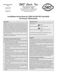
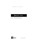
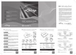
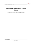
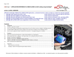
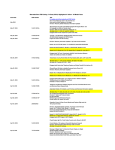
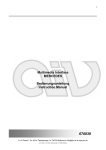
mObridge Audio & Bluetooth Install Notes V0.1
Version 0.1
mObridge Audio iPod &
Bluetooth Install Notes
For use with the mObridge Audio iPod & Bluetooth range of products
www.mobridge-usa.com
mObridge Inc · 800 S. Pacific Coast Hwy, Suite 8-348, Redondo Beach, CA 90722 USA
· 1-888-7-MOBRIDGE · [email protected]
mObridge Audio & Bluetooth Install Notes V0.1
mObridge Audio iPod & Bluetooth Install Notes............................................................... 1
Common Install Notes ........................................................................................................ 3
mObridge Wiring Connection............................................................................................. 5
mObridge Audio & Bluetooth Kit .................................................................................... 10
Connections....................................................................................................................... 11
Microphone Connection................................................................................................ 12
Firmware Updates & Vehicle Configuration.................................................................... 14
Vehicle Coding & Software Versions............................................................................... 15
BMW............................................................................................................................. 15
Mini............................................................................................................................... 15
Audi............................................................................................................................... 15
Porsche.......................................................................................................................... 16
Mercedes ....................................................................................................................... 16
Landrover...................................................................................................................... 16
Trouble Shooting .............................................................................................................. 17
www.mobridge-usa.com
mObridge Inc · 800 S. Pacific Coast Hwy, Suite 8-348, Redondo Beach, CA 90722 USA
· 1-888-7-MOBRIDGE · [email protected]
mObridge Audio & Bluetooth Install Notes V0.1
Common Install Notes
1. Never bend fiber optic lines sharply (acutely) or at
more than about 2” radius or permanent damage
may result to the fiber.
2. Battery power (+) to the unit must be fused by a
value of 5A. On a 10A circuit or the radio’s circuit
is acceptable (safe, OK).
3. Power to mObridge must be constant battery (B+).
It cannot be from a vehicle power plug. Vehicle
power plug is not consistently constant power,
despite appearances or first apparent behavior.
Best location to source power is at the Head Unit’s
own power or CD changer’s power wire (e.g., in
Porsche red wire with yellow stripe).
4. If vehicle is intended to be serviced (diagnosed) by
the dealer, bypass switch should be put into the
ON mode. It is not plug and play (vehicle power
cycle must be done / complete sleep/wake cycle in
order to properly initialize MOST bus in
mObridge’s bypass / non-bypass mode. Bypass
mode can be activated by toggling the bypass
www.mobridge-usa.com
mObridge Inc · 800 S. Pacific Coast Hwy, Suite 8-348, Redondo Beach, CA 90722 USA
· 1-888-7-MOBRIDGE · [email protected]
mObridge Audio & Bluetooth Install Notes V0.1
switch 5-6 times in a five second window. The
MOST bus will be broken for two seconds.
5. MOST bus is not hot “plug and play”. Do not
expect system to immediately work after plugging
in units and turning on vehicle. If any MOST pieces
have been.
6. BMW Vehicles require coding. mObridge can only
supply limited support in the area of coding BMWs,
and will not refund if the mObridge unit cannot be
fitted due to an inability to code the vehicle.
For further information on the coding of BMWs please
refer to the Autologic web site.
7. MY2009 and MY2010 vehicles are not supported at this
time.
8. The factory microhone cannot be used due to incorrect
mathcin impedances
www.mobridge-usa.com
mObridge Inc · 800 S. Pacific Coast Hwy, Suite 8-348, Redondo Beach, CA 90722 USA
· 1-888-7-MOBRIDGE · [email protected]
mObridge Audio & Bluetooth Install Notes V0.1
mObridge Wiring Connection
The mObridge main power connector contains the optical fiber input as well as a 4 pin
wiring insert. This 4 pin wiring insert, if inspected closely, has numbering on the pins.
Although both the BMW and mObridge share the same connector as the BMW CDC and
Sat Radio wiring, the pinning is slightly different. If the user tries to plug the connetor
directly in without changing the BMW plug wiring into the mObridge unit, the user will
burn a fuse out in the vehicle.
B+ Power and GND must be
relocated in the BMW factory
connector to suit the
mObridge connection
Pins 3 & 4 in the factory
connector must be removed
and taped if they are present
Pin
No.
BMW Factory
Unit Function
mObridge
Function
1
+12V Constant
battery power
(typically red with
stripe)
Battery Ground
(always brown)
2
Battery Ground
(always brown)
3
Other function
+12V Constant
battery power (always
orange)
none
4
Other function
Bypass switch
Figure 1 BMW pin out against mObridge pin out
As can be seen from Figure 1, the BMW factory wiring connector needs to have pins 1 &
2 swapped to be compatible with the mObridge wiring.
www.mobridge-usa.com
mObridge Inc · 800 S. Pacific Coast Hwy, Suite 8-348, Redondo Beach, CA 90722 USA
· 1-888-7-MOBRIDGE · [email protected]
mObridge Audio & Bluetooth Install Notes V0.1
Figure 2 Rear view of the 4 pin connector
Figure 2 illustrates the pin out wiring of the electrical 4 pin insert. For mObridge units
pin 1 is always ground and pin 2 is always constant 12V+ supply. This view is from the
back of the connector.
www.mobridge-usa.com
mObridge Inc · 800 S. Pacific Coast Hwy, Suite 8-348, Redondo Beach, CA 90722 USA
· 1-888-7-MOBRIDGE · [email protected]
mObridge Audio & Bluetooth Install Notes V0.1
Figure 3 Front view of the 4 pin connector
Figure 3 clearly demonstrates the pin numbering visible on the outside of the connector.
Pin 1 is always ground on the mObridge wiring and pin 2 is always constant 12V+
battery on the mObridge connector.
www.mobridge-usa.com
mObridge Inc · 800 S. Pacific Coast Hwy, Suite 8-348, Redondo Beach, CA 90722 USA
· 1-888-7-MOBRIDGE · [email protected]
mObridge Audio & Bluetooth Install Notes V0.1
Figure 4 Rear view of fully assembled mObridge connector
Here we have the rear view of the fully assembled 4 position mObridge connector. Note
that the brown wire is ground in position 1 and the orange wire is 12V+ battery in
position 2.
The white wire is the ‘bypass’ wire that will be connected to the bypass toggle switch.
www.mobridge-usa.com
mObridge Inc · 800 S. Pacific Coast Hwy, Suite 8-348, Redondo Beach, CA 90722 USA
· 1-888-7-MOBRIDGE · [email protected]
mObridge Audio & Bluetooth Install Notes V0.1
Figure 5 Fully disassembled mObridge wiring assembly
Finally we have broken down the complete wiring setup into the MOST connections, 3
wires of the mObridge harness and their connections and the pin numbering of the 4
position insert into the MOST shell.
www.mobridge-usa.com
mObridge Inc · 800 S. Pacific Coast Hwy, Suite 8-348, Redondo Beach, CA 90722 USA
· 1-888-7-MOBRIDGE · [email protected]
mObridge Audio & Bluetooth Install Notes V0.1
mObridge Audio & Bluetooth Kit
The mObridge Audio kit contains the following pieces:
1)
2)
3)
4)
5)
6)
7)
mObridge Audio unit configured for CD Changer replacement
mObridge power wiring harness
MOST optical fiber loom patch harness
MOST optical loop to loop out existing CD Changer
iPod high quality automotive spec cable
3.5mm Audio auxiliary input cable
Parrot Dual microphone
1) mObridge Audio &
Bluetooth interface
4) MOST Loop
7) Microphone
5) iPod cable
2) & 3) mObridge
Wiring loom & optical
harness
6) Auxiliary 3.5mm
Figure 6 Cable connections to the mObridge Audio & Bluetooth interface
Figure 6 contains all the cable connections that are in the mObridge Audio kit.
www.mobridge-usa.com
mObridge Inc · 800 S. Pacific Coast Hwy, Suite 8-348, Redondo Beach, CA 90722 USA
· 1-888-7-MOBRIDGE · [email protected]
mObridge Audio & Bluetooth Install Notes V0.1
Connections
The mObridge Audio connections are straight forward. The 3.5mm Auxiliary cable can
be fitted or simply left out. This is a user choice.
The iPod cable 20 pin rectangle connector is fitted into the ‘MP3 Player’ port of the
mObridge Audio interface and this can then be fitted into the car and run into either the
glove box or up into the centre console depending on user choice.
The mObridge Wiring harness is generally recommended to be fitted into where the
existing CD Changer wiring is fitted or directly using the power connections on the back
of the vehicles head units.
Note: mObridge MOST interfaces must be fitted to permanent power.
Do not worry as you cannot flatten the battery. The mObridge interface power circuit is
only awake when the optical fiber ring is in operation. Once the optical fiber ring has
slept then it is impossible to still be powering the mObridge interface.
The following figure illustrates the connections into the mObridge interface.
Figure 7 Connections for the mObridge Audio & Bluetooth Interface
www.mobridge-usa.com
mObridge Inc · 800 S. Pacific Coast Hwy, Suite 8-348, Redondo Beach, CA 90722 USA
· 1-888-7-MOBRIDGE · [email protected]
mObridge Audio & Bluetooth Install Notes V0.1
The final step of the interface connections is the optical patch. The kit contains an inline
connector already inserted onto the patch cable. Ideally the mObridge interface can use
the existing CD Changer MOST connection or the MOST connections from the head
unit.
Patching the MOST connections can be done by following the arrows on the MOST
connectors themselves. By carefully reversing the output of the head unit connection and
inserting the input cable side of the mObridge connector (this is the optical strand without
the inline connector) and then use the mObridge optical strand with the inline connector
to connect back to the optical fiber that was originally taken from the head unit or other
optical interface within the car.
Microphone Connection
The microphone connection into the mObridge interface has keying and a locking
mechanism. If not inserted correct it may lead to a loss of microphone audio.
Microphone
key
Figure 8 Microphone key
Figure 8 illustrates the key on the microphone and the slot in the mObridge interface box
for which it needs to be inserted.
www.mobridge-usa.com
mObridge Inc · 800 S. Pacific Coast Hwy, Suite 8-348, Redondo Beach, CA 90722 USA
· 1-888-7-MOBRIDGE · [email protected]
mObridge Audio & Bluetooth Install Notes V0.1
Figure 9 A correctly inserted microphone
Figure 9 shows us a correctly inserted microphone to ensure correct operation.
www.mobridge-usa.com
mObridge Inc · 800 S. Pacific Coast Hwy, Suite 8-348, Redondo Beach, CA 90722 USA
· 1-888-7-MOBRIDGE · [email protected]
mObridge Audio & Bluetooth Install Notes V0.1
Bypass Switch
The bypass switch is provided to allow for the mObridge unit to become ‘invisible’ on
the MOST vehicle bus system. The main use of this function is to facilitate dealer
services when the diagnostic computer is in use and to ensure the mObridge unit does not
interfere with the vehicle diagnostics.
The function can be enabled by toggling this switch 5 times. Once the bypass feature has
been activated, the MOST bus will be broken for 2 seconds and the feature cannot be
activated again for a further 10 seconds.
Once the bypass switch has been activated, it will remain activated across power cycles
until the bypass is de-activated by toggling the switch again 5 times within a 5 second
time frame.
Firmware Updates & Vehicle
Configuration
The mObridge range of products provides the ability to update the firmware of your unit
as well as configure the unit for any vehicle type, vehicle settings and specific vehicle
setup. mObridge is constantly striving for perfection in all products as well as adding new
features.
The latest firmware can be found on our webpage here:
www.mobridgeinc.com/support/updates
The mObridge Wizard also provides and easy to use step by step guide on vehicle setup
and will automatically produce an SD memory card files mObridge.ini allowing users to
make changes to the mObridge setup such as vehicle type.
The mObridge Wizard can be downloaded here:
www.mobridgeinc.com/node/109
www.mobridge-usa.com
mObridge Inc · 800 S. Pacific Coast Hwy, Suite 8-348, Redondo Beach, CA 90722 USA
· 1-888-7-MOBRIDGE · [email protected]
mObridge Audio & Bluetooth Install Notes V0.1
Vehicle Coding & Software Versions
BMW
•
•
•
•
All BMW vehicles are required to be "coded" - ie have the CD changer and
telephone enabled in the vehicle. This requires some knowledge and access to
either the dealer diagnostic tools or an aftermarket BMW coding solution such as
Autologic. mObridge can only supply limited support in the area of coding
BMWs, and will not refund if the mObridge unit cannot be fitted due to an
inability to code the vehicle.
For further information on the coding of BMWs please refer to the Autologic web
site.
CD Changer Retention is not supported if the iPod functionality is required.
MY2009 vehicles are not supported at this time.
MY2005 6-Series and 7-Series may need a Software Update of the i-Drive to
support CD Text. This is the responsibility of the installer to ensure the vehicle
supports CD-Text. mObridge cannot offer support in this case.
Mini
•
•
•
All Minis are required to be "coded" - ie have the CD changer and telephone
enabled in the vehicle. This requires some knowledge and access to either the
dealer diagnostic tools or an aftermarket Mini coding solution such as Autologic.
mObridge can only supply limited support in the area of coding Minis, and
will not refund if the mObridge unit cannot be fitted due to an inability to
code the vehicle.
For further information on the coding of BMWs please refer to the Autologic web
site.
CD Changer Retention not supported if iPod function is required.
MY2009 vehicles are not supported at this time.
Audi
•
•
•
•
Monochrome MMI is not supported.
CD Changer Retention is supported.
US Spec Audis require coding of the diagnostic gateway for telephone
functionality. We have a documented procedure in our knowledgebase.
2004-2005 US Spec Audis require telematics disablement, again refer to the
above document.
www.mobridge-usa.com
mObridge Inc · 800 S. Pacific Coast Hwy, Suite 8-348, Redondo Beach, CA 90722 USA
· 1-888-7-MOBRIDGE · [email protected]
mObridge Audio & Bluetooth Install Notes V0.1
•
•
•
European Spec Audi MMIs require 34.60 or greater firmware. Please refer to
your Audi dealer/specialist for MMI software upgrades.
US Spec Audi MMIs require 33.60 or greater firmware. Please refer to your Audi
dealer/specialist for MMI software upgrades.
Audi software version can be found by holding the ‘Setup’ and ‘Return’ button on
the Audi MMI system for 5 seconds.
Porsche
•
•
•
•
•
PCM 3.0 is not supported.
CD Changer Retention not supported if iPod function is required.
Pre-2005 Porsche Models require Telephone coding using PIWIS.
CD Changer must be coded off using PIWIS.
Only PCM units with Telephone Buttons fitted are supported.
Mercedes
•
•
•
CD Changer Retention not possible.
2004 Model S-Class require a special configuration in the mObridge ABT2010.
Please refer to the install notes.
Some Euro Spec Mercedes may need Telephone coded into the vehicle using
StarDiagnose.
Note: 2004 S class vehicles require the mObridge to be configuered to ‘old
Mercedes’ and this can be done by using the Wizard software under the vehicle
variant tab. The installer can use either the SD card, USB cable connection or the
Bluetooth connection. Please refer to the Wizard User Guide for Wizard
connections.
Landrover
•
iPod is not supported at this time, so ABT2010 is bluetooth phone only at this
point.
www.mobridge-usa.com
mObridge Inc · 800 S. Pacific Coast Hwy, Suite 8-348, Redondo Beach, CA 90722 USA
· 1-888-7-MOBRIDGE · [email protected]
mObridge Audio & Bluetooth Install Notes V0.1
Trouble Shooting
Upon first install it is advisable to let the entire car go to ‘sleep’ for 10 minutes and
recover gracefully. Optical fiber equipped vehicles do not take to kindly to installs
without a graceful startup.
A good indication that the mObridge unit is running is the fact that the iPod screen will
light up and display the mObridge logo.
Q) The Head Unit no longer wakes up?
A) Double check the optical connections.
If the head unit can not see the entire loop being completed with light, then the head unit
is likely to turn itself off as it has a problem.
See if there is light coming into the mObridge connector and check the arrow on top of
the connector itself and make sure light is traveling in the correct direction.
Q) I’ve installed the unit, the optical ring is working but the unit does not appear in
the head unit?
A) Vehicle may need coding.
BMW vehicle in particular require coding to enable options such as the CD changer.
Mercedes, Porsche and Audi do not require coding for the CD Changer.
Early 2002-2005 vehicle also do not support MP3 file browsing. In this case the
mObridge interface needs to be configured for BMW-nonmp3 mode otherwise the CD
Changer interface will not show any discs as being available as they are reported as MP3
discs.
Also double check the bypass mode switch.
Q) The iPod connection causes erratic wakeup on startup?
A) The mObridge interface is not wired to permanent power.
Check the wiring connection. This needs to be permanent power.
Q) My iPod volume level is lower than the radio?
A) The mObridge interface has the same audio gain as the radio.
Likely that iTunes has not been set to level out the iPod volume.
Q) I cannot browse the iPod?
A) Please refer to the user manual included in the kit.
Q) My base model Mercedes or Porsche radio does not show me track name?
www.mobridge-usa.com
mObridge Inc · 800 S. Pacific Coast Hwy, Suite 8-348, Redondo Beach, CA 90722 USA
· 1-888-7-MOBRIDGE · [email protected]
mObridge Audio & Bluetooth Install Notes V0.1
A) These base model radios do not support text.
The mObridge interface needs to be configured for ‘numbered’ browsing liming the user
to the first 5 playlists or playlists numbered DISC1, DISC2 etc. Please refer to the
mObridge User Manual for correct operation.
Q) My microphone volume is to low?
A) The microphone volume gain can be turned up.
The default is 4 but it can go all the way to 15. In testing we have found that anything
above 6-7 results in clipping and the audio becomes worst. Gain can be adjusted by
using the mObridge Wizard software and either connecting to the unit via Bluetooth
itself, via the USB cable interface or simply generating an SD card with the parameters
adjusted and inserting into the mObridge unit.
Q) I cannot pair my new phone but the old phone works?
A) Too many phones have been paired without deletion.
The mObridge Bluetooth device can supported up to 4 paired phones. If new phones/PC
are required to be paired then something needs to be deleted. Please refer to the
Bluetooth user’s manual on the sequence to perform this.
Q) Only 150 of my contacts are on the head unit?
A) Some older head units (Porsche for example) only support a limited amount.
This dates back to the time of SIM cards when cards could only hold 100 contacts.
Please refer to the mObridge Bluetooth user manual on exact manufacturers head units.
www.mobridge-usa.com
mObridge Inc · 800 S. Pacific Coast Hwy, Suite 8-348, Redondo Beach, CA 90722 USA
· 1-888-7-MOBRIDGE · [email protected]