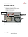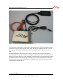
1
mObridge Audio Install Notes V0.2
mObridge Audio iPod Install
Notes
For use with the mObridge Audio iPod range of products
www.mobridge.us
mObridge Inc
[email protected]
mObridge Audio Install Notes V0.2
mObridge Audio iPod Install Notes.................................................................................... 1
Common Install Notes ........................................................................................................ 3
mObridge Wiring Connection............................................................................................. 5
mObridge Audio Kit ......................................................................................................... 10
Connections....................................................................................................................... 11
Firmware Updates & Vehicle Configuration.................................................................... 13
Vehicle Coding & Software Versions............................................................................... 14
BMW............................................................................................................................. 14
Mini............................................................................................................................... 14
Audi............................................................................................................................... 14
Porsche.......................................................................................................................... 14
Mercedes ....................................................................................................................... 15
Saab............................................................................................................................... 15
Trouble Shooting .............................................................................................................. 16
www.mobridge.us
mObridge Inc
[email protected]
mObridge Audio Install Notes V0.2
Common Install Notes
1. Never bend fiber optic lines sharply (acutely) or at
more than about 2” radius or permanent damage
may result to the fiber.
2. Battery power (+) to the unit must be fused by a
value of 5A. On a 10A circuit or the radio’s circuit
is acceptable (safe, OK).
3. Power to mObridge must be constant battery (B+).
It cannot be from a vehicle power plug. Vehicle
power plug is not consistently constant power,
despite appearances or first apparent behavior.
Best location to source power is at the Head Unit’s
own power or CD changer’s power wire (e.g., in
Porsche red wire with yellow stripe).
4. If vehicle is intended to be serviced (diagnosed) by
the dealer, bypass switch should be put into the
ON mode. It is not plug and play (vehicle power
cycle must be done / complete sleep/wake cycle in
order to properly initialize MOST bus in
mObridge’s bypass / non-bypass mode. Bypass
mode can be activated by toggling the bypass
switch 5-6 times in a five second window. The
MOST bus will be broken for two seconds.
www.mobridge.us
mObridge Inc
[email protected]
mObridge Audio Install Notes V0.2
5. MOST bus is not hot “plug and play”. Do not
expect system to immediately work after plugging
in units and turning on vehicle. If any MOST pieces
have been.
6. BMW Vehicles require coding. mObridge products
now support auto coding meaning they will
automatically detect which vehicle they are in and
code the car themselves.
www.mobridge.us
mObridge Inc
[email protected]
mObridge Audio Install Notes V0.2
mObridge Wiring Connection
The mObridge main power connector contains the optical fiber input as well as a 4 pin
wiring insert. This 4 pin wiring insert, if inspected closely, has numbering on the pins.
Although both the BMW and mObridge share the same connector as the BMW CDC and
Sat Radio wiring, the pinning is slightly different. If the user tries to plug the connetor
directly in without changing the BMW plug wiring into the mObridge unit, the user will
burn a fuse out in the vehicle.
B+ Power and GND must be
relocated in the BMW factory
connector to suit the
mObridge connection
Pins 3 & 4 in the factory
connector must be removed
and taped if they are present
Pin
No.
BMW Factory
Unit Function
mObridge
Function
1
+12V Constant
battery power
(typically red with
stripe)
Battery Ground
(always brown)
2
Battery Ground
(always brown)
3
Other function
+12V Constant
battery power (always
orange)
none
4
Other function
Bypass switch
Figure 1 BMW pin out against mObridge pin out
As can be seen from Figure 1, the BMW factory wiring connector needs to have pins 1 &
2 swapped to be compatible with the mObridge wiring.
www.mobridge.us
mObridge Inc
[email protected]
mObridge Audio Install Notes V0.2
Figure 2 Rear view of the 4 pin connector
Figure 2 illustrates the pin out wiring of the electrical 4 pin insert. For mObridge units
pin 1 is always ground and pin 2 is always constant 12V+ supply. This view is from the
back of the connector.
www.mobridge.us
mObridge Inc
[email protected]
mObridge Audio Install Notes V0.2
Figure 3 Front view of the 4 pin connector
Figure 3 clearly demonstrates the pin numbering visible on the outside of the connector.
Pin 1 is always ground on the mObridge wiring and pin 2 is always constant 12V+
battery on the mObridge connector.
www.mobridge.us
mObridge Inc
[email protected]
mObridge Audio Install Notes V0.2
Figure 4 Rear view of fully assembled mObridge connector
Here we have the rear view of the fully assembled 4 position mObridge connector. Note
that the brown wire is ground in position 1 and the orange wire is 12V+ battery in
position 2.
The white wire is the ‘bypass’ wire that will be connected to the bypass toggle switch.
www.mobridge.us
mObridge Inc
[email protected]
mObridge Audio Install Notes V0.2
Figure 5 Fully disassembled mObridge wiring assembly
Finally we have broken down the complete wiring setup into the MOST connections, 3
wires of the mObridge harness and their connections and the pin numbering of the 4
position insert into the MOST shell.
www.mobridge.us
mObridge Inc
[email protected]
mObridge Audio Install Notes V0.2
mObridge Audio Kit
The mObridge Audio kit contains the following pieces:
1)
2)
3)
4)
5)
6)
mObridge Audio unit configured for CD Changer replacement
mObridge power wiring harness
MOST optical fiber loom patch harness
MOST optical loop to loop out existing CD Changer
iPod high quality automotive spec cable
3.5mm Audio auxiliary input cable
2) & 3) mObridge
Wiring loom & optical
harness
6) Auxiliary 3.5mm
4) MOST Loop
5) iPod cable
1) mObridge Audio
interface
Figure 6 Cable connections to the mObridge Audio interface
Figure 6 contains all the cable connections that are in the mObridge Audio kit.
www.mobridge.us
mObridge Inc
[email protected]
mObridge Audio Install Notes V0.2
Connections
The mObridge Audio connections are straight forward. The 3.5mm Auxiliary cable can
be fitted or simply left out. This is a user choice.
The iPod cable 20 pin rectangle connector is fitted into the ‘MP3 Player’ port of the
mObridge Audio interface and this can then be fitted into the car and run into either the
glove box or up into the centre console depending on user choice.
The mObridge Wiring harness is generally recommended to be fitted into where the
existing CD Changer wiring is fitted or directly using the power connections on the back
of the vehicles head units.
Note: mObridge MOST interfaces must be fitted to permanent power.
Do not worry as you cannot flatten the battery. The mObridge interface power circuit is
only awake when the optical fiber ring is in operation. Once the optical fiber ring has
slept then it is impossible to still be powering the mObridge interface.
The following figure illustrates the connections into the mObridge interface.
www.mobridge.us
mObridge Inc
[email protected]
mObridge Audio Install Notes V0.2
Figure 7 Connections for the mObridge Audio Interface
The final step of the interface connections is the optical patch. The kit contains an inline
connector already inserted onto the patch cable. Ideally the mObridge interface can use
the existing CD Changer MOST connection or the MOST connections from the head
unit.
Patching the MOST connections can be done by following the arrows on the MOST
connectors themselves. By carefully reversing the output of the head unit connection and
inserting the input cable side of the mObridge connector (this is the optical strand without
the inline connector) and then use the mObridge optical strand with the inline connector
to connect back to the optical fiber that was originally taken from the head unit or other
optical interface within the car.
www.mobridge.us
mObridge Inc
[email protected]
mObridge Audio Install Notes V0.2
Bypass Switch
The bypass switch is provided to allow for the mObridge unit to become ‘invisible’ on
the MOST vehicle bus system. The main use of this function is to facilitate dealer
services when the diagnostic computer is in use and to ensure the mObridge unit does not
interfere with the vehicle diagnostics.
The function can be enabled by toggling this switch 5 times. Once the bypass feature has
been activated, the MOST bus will be broken for 2 seconds and the feature cannot be
activated again for a further 10 seconds.
Once the bypass switch has been activated, it will remain activated across power cycles
until the bypass is de-activated by toggling the switch again 5 times within a 5 second
time frame.
Firmware Updates & Vehicle
Configuration
The mObridge range of products provides the ability to update the firmware of your unit
as well as configure the unit for any vehicle type, vehicle settings and specific vehicle
setup. mObridge is constantly striving for perfection in all products as well as adding new
features.
The latest firmware can be found on our webpage here:
www.mobridge.us
The mObridge Wizard also provides and easy to use step by step guide on vehicle setup
and will automatically produce an SD memory card files mObridge.ini allowing users to
make changes to the mObridge setup such as vehicle type.
The mObridge Wizard can be downloaded here:
www.mobridge.us/wizard
www.mobridge.us
mObridge Inc
[email protected]
mObridge Audio Install Notes V0.2
Vehicle Coding & Software Versions
BMW
•
•
•
•
•
All BMW vehicles are required to be "coded" - ie have the CD changer and
telephone enabled in the vehicle. All mObridge products now self code
themselves into the car. The use of an Autologic disgnostic computer can also be
utilized. For further information on the coding of BMWs please refer to the
Autologic web site.
CD Changer Retention is not supported if the iPod functionality is required.
MY2004 5 series may need a Software Update of the i-Drive to support CD Text.
This is the responsibility of the installer to ensure the vehicle supports CD-Text.
mObridge cannot offer support in this case.
BMW E65 7 series from 2002->2007 does not support text mode
From late 2009 the base mode professional radio may not have MOST and it also
may be manufactured by Continental AG. The Continental based radios are not
compatible.
Mini
•
•
•
All Minis vehicles are required to be "coded" - ie have the CD changer and
telephone enabled in the vehicle. All mObridge products now self code
themselves into the car. The use of an Autologic disgnostic computer can also be
utilized. For further information on the coding of BMWs please refer to the
Autologic web site.
CD Changer Retention not supported if iPod function is required.
Audi
•
•
Monochrome MMI is not supported.
CD Changer Retention is supported.
Porsche
•
•
PCM 3.0 is not supported at this time.
CD Changer Retention not supported.
www.mobridge.us
mObridge Inc
[email protected]
mObridge Audio Install Notes V0.2
Mercedes
•
CD Changer Retention not possible.
Saab
•
Can be fitetd as either the rear or front CD changer
www.mobridge.us
mObridge Inc
[email protected]
mObridge Audio Install Notes V0.2
Trouble Shooting
Upon first install it is advisable to let the entire car go to ‘sleep’ for 10 minutes and
recover gracefully. Optical fiber equipped vehicles do not take to kindly to installs
without a graceful startup.
A good indication that the mObridge unit is running is the fact that the iPod screen will
light up and display the mObridge logo.
Q) The Head Unit no longer wakes up?
A) Double check the optical connections.
If the head unit can not see the entire loop being completed with light, then the head unit
is likely to turn itself off as it has a problem.
See if there is light coming into the mObridge connector and check the arrow on top of
the connector itself and make sure light is traveling in the correct direction.
Q) I’ve installed the unit, the optical ring is working but the unit does not appear in
the head unit?
A) Vehicle may need coding.
BMW vehicle in particular require coding to enable options such as the CD changer.
Mercedes, Porsche and Audi do not require coding for the CD Changer.
Early 2002-2005 vehicle also do not support MP3 file browsing. In this case the
mObridge interface needs to be configured for BMW-nonmp3 mode otherwise the CD
Changer interface will not show any discs as being available as they are reported as MP3
discs.
Also double check the bypass mode switch.
Q) The iPod connection causes erratic wakeup on startup?
A) The mObridge interface is not wired to permanent power.
Check the wiring connection. This needs to be permanent power.
Q) My iPod volume level is lower than the radio?
A) The mObridge interface has the same audio gain as the radio.
Likely that iTunes has not been set to level out the iPod volume.
Q) I cannot browse the iPod?
A) Please refer to the user manual included in the kit.
Q) My base model Mercedes or Porsche radio does not show me track name?
A) These base model radios do not support text.
www.mobridge.us
mObridge Inc
[email protected]
mObridge Audio Install Notes V0.2
The mObridge interface needs to be configured for ‘numbered’ browsing liming the user
to the first 5 playlists or playlists numbered DISC1, DISC2 etc. Please refer to the
mObridge User Manual for correct operation.
www.mobridge.us
mObridge Inc
[email protected]