1
8.2
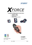
Joystick installation
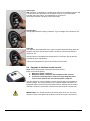
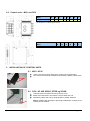
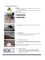
The joystick panel, (single or double), comes complete with;
Joystick with gasket and connection plug(s)
Drill template
Self tapping screws
Manual
8.2.1
Mounting
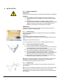
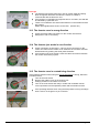
Turn off the main switch to the electrical thruster.
Select the mounting position for the joystick panel. The desired position must
be even and in a location that will prevent water from rain or sea spray to be
able to access the back of the panel. Remove all grease, dust or dirt before
affixing the drill template.
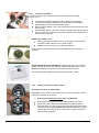
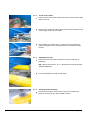
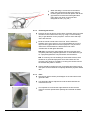
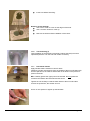
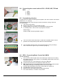
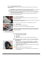
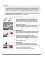
Mount the drill template sticker and use a hole saw and cutter or file to
remove all needed area for installation. Pre-drill the four fastening holes with
Ø2,4mm, (3/32”).
Remove the drill template and remove the red cover film from the gasket.
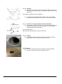
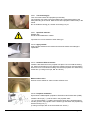
Install the panel carefully and fix it in place with the four black stainless
screws.
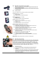
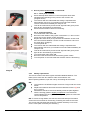
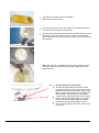
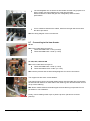
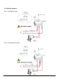
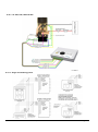
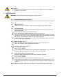
Connect the wires to the panel as shown on the connection diagram(s).
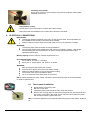
The wires are connected by pressing in the button placed under the hole
while the wire is being pushed into the hole. Release the button when the wire
is in place.
Check for good connection by pulling gently in the wires.
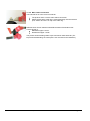
Correct connection is;
1. White (Direction 1)
2. Brown (Common)
3. Green (Direction 2)
4. Yellow (+ supply from 1 A fuse connected after thruster main switch
or directly to MCU from MCU serial no. 200473 and later.)
8.3
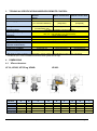
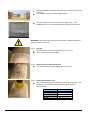
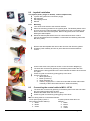
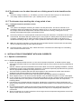
Connecting the control cable to MCU - XF20
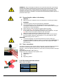
The wires are connected by pressing in the button placed over the hole while
the wire is being pushed into the hole.
Release the button when the wire is in place.
Check for good connection by pulling gently in the wires.
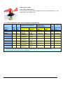
NB: The wiring must be connected as follows:
Touch panel (and joy stick if
Joystick (if MCU serial above no.
MCU serial no below 200473):
200473.):
1. White
1. White
2. Brown
2. Brown
3. Green
3. Green
4. Yellow
XF
Rev: 8, 2010-01-05
Page 21