1
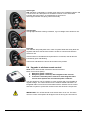
Installation and user manual
XF 20 - XF 40R - XF 60R
XF 75R - XF 90R
According to NS-EN ISO 9001:2000
FCC ID: R78-RC-01
R78-ECU-01
Part no. 117-00164
XF
Rev: 8, 2010-01-05
Page 1
Contents
1
INTRODUCTION ............................................................................................................................................. 3
2
2.1
2.2
OPERATION ................................................................................................................................................... 4
Intelligent electronic protection control ..................................................................................................... 4
Operation of joystick / touch panel ............................................................................................................. 5
2.2.1
2.3
2.3.1
2.4
Panel versions ..........................................................................................................................................................5
Operating instructions .................................................................................................................................. 5
Directions for use......................................................................................................................................................5
Upgrade to wireless remote control ............................................................................................................ 6
2.4.1
2.4.2
2.4.3
Antenna installation ..................................................................................................................................................7
Coding of wireless remote control ............................................................................................................................ 7
Battery replacement .................................................................................................................................................8
3
TECHNICAL SPECIFICATIONS WIRELESS REMOTE CONTROL ............................................................. 9
4
4.1
4.2
DIMENSIONS .................................................................................................................................................. 9
XForce thrusters ............................................................................................................................................ 9
Control units – MCU and RCU ................................................................................................................... 10
5
5.1
5.2
INSTALLATION OF CONTROL UNITS ....................................................................................................... 10
MCU - XF20 .................................................................................................................................................. 10
RCU - XF 40R, XF60R, XF75R og XF90R ................................................................................................... 10
6
6.1
INSTALLATION ............................................................................................................................................ 11
Tunnel installation ....................................................................................................................................... 11
6.1.1
6.1.2
6.1.3
6.1.4
6.1.5
6.1.6
6.1.7
6.1.8
6.1.9
6.1.10
6.1.11
6.1.12
7
7.1
THRUSTER INSTALLATION ....................................................................................................................... 16
Preparations ................................................................................................................................................ 16
7.1.1
7.1.2
7.1.3
7.1.4
7.1.5
7.1.6
7.1.7
7.1.8
7.1.9
7.1.10
7.1.11
7.1.12
8
8.1
8.2
Determine the centre lines ...................................................................................................................................... 16
Installation template................................................................................................................................................ 16
Pre-drill ................................................................................................................................................................... 17
Drilling holes for the bracket bolts........................................................................................................................... 17
Drilling the insertion hole ........................................................................................................................................ 17
Test mounting (I) .................................................................................................................................................... 18
Placement of bolts .................................................................................................................................................. 18
Test mounting (II) ................................................................................................................................................... 19
Specified sealants: ................................................................................................................................................. 19
Apply sealant .......................................................................................................................................................... 19
Install the XForce thruster ...................................................................................................................................... 19
Propeller installation ............................................................................................................................................... 19
ELECTRICAL CONNECTIONS .................................................................................................................... 20
Touch panel installation ............................................................................................................................. 20
Joystick installation .................................................................................................................................... 21
8.2.1
8.3
8.4
8.5
8.6
8.7
8.8
8.9
8.10
XF
Drilling tool kit ......................................................................................................................................................... 11
Choosing and marking the location ........................................................................................................................ 11
Cutting holes........................................................................................................................................................... 11
Tunnel centre holes ................................................................................................................................................ 12
Adapting the tunnel................................................................................................................................................. 12
Cleaning before fastening ....................................................................................................................................... 12
Prevent filling from running out ............................................................................................................................... 13
Fastening the tunnel ............................................................................................................................................... 14
Filler........................................................................................................................................................................ 14
Grinding .................................................................................................................................................................. 15
Directions for high speed boat special installations ................................................................................................ 15
Coating ................................................................................................................................................................... 15
Mounting ................................................................................................................................................................. 21
Connecting the control cable to MCU - XF20 ........................................................................................... 21
Connecting the control cable to RCU - XF40R, 60R, 75R and 90 R ....................................................... 22
Contradicting direction ............................................................................................................................... 22
XF20 - Connecting Motor Control Unit (MCU) .......................................................................................... 22
Connecting to the bow thuster .................................................................................................................. 23
Connecting the cables to the battery ........................................................................................................ 24
Fuse connections ........................................................................................................................................ 24
Recommended main switch ....................................................................................................................... 24
Rev: 8, 2010-01-05
Page 2
8.10.1
8.11
8.12
8.12.1
8.12.2
8.12.3
8.12.4
9
9.1
Preface/introduction................................................................................................................................................ 31
Battery .......................................................................................................................................................... 32
11.2.1
11.2.2
11.2.3
11.2.4
1
Intelligent electronic protection control ................................................................................................................... 31
INSTALLATION OF EQUIPMENT WITH HIGH CURRENTS ...................................................................... 31
Special considerations ............................................................................................................................... 31
11.1.1
11.2
Mechanical check ................................................................................................................................................... 28
Corrosion check...................................................................................................................................................... 28
Battery/charger check............................................................................................................................................. 28
High current cable/connections check .................................................................................................................... 28
Joystick/operator panel check ................................................................................................................................ 29
Belt drive maintenance ........................................................................................................................................... 29
Inspect the belt ....................................................................................................................................................... 29
TROUBLESHOOTING .................................................................................................................................. 29
The thruster does not work ........................................................................................................................ 29
The thruster does not work or has an unexpectedly low performance ................................................. 29
The thruster runs in wrong direction ........................................................................................................ 30
The thruster just works in one direction ................................................................................................... 30
The thruster runs in contradicting direction ............................................................................................ 30
The thruster runs for short intervals or a clicking sound is to be heard from the MCU ..................... 31
The thruster stops working after a long period of use ............................................................................ 31
10.7.1
11
11.1
XF 20 Relay version ............................................................................................................................................... 26
XF 20 electronic version ......................................................................................................................................... 26
XF 40R, 60R, 75R and 90R .................................................................................................................................... 27
Single and double joystick ...................................................................................................................................... 27
MAINTENANCE ............................................................................................................................................ 28
Seasonal maintenance/check .................................................................................................................... 28
9.1.1
9.1.2
9.1.3
9.1.4
9.1.5
9.1.6
9.1.7
10
10.1
10.2
10.3
10.4
10.5
10.6
10.7
Main switch terminal ............................................................................................................................................... 25
XForce thruster cable, fuse and battery requirements ........................................................................... 25
Wiring diagrams .......................................................................................................................................... 26
Battery-cables/lugs ................................................................................................................................................. 32
Battery connection .................................................................................................................................................. 32
Fuse connection ..................................................................................................................................................... 32
Main switch connection .......................................................................................................................................... 33
INTRODUCTION
First of all, we would like to thank you for choosing the XForce Thruster. Engbo AS has for several years
supplied Volvo Penta with thrusters, distributed as QL thrusters through Volvo Penta dealers and distributors. In
late 2006, Engbo and Volvo Penta agreed that distributing through two channels and brand names would make
our thrusters even more available. Together with Engbo anchoring and mooring systems, the thrusters
constitute a complete system for manoeuvring and mooring your vessel. The control units for both thrusters and
winches are based on the same modules, which makes it possible to manoeuvre and anchor using one single
wireless remote control.
To achieve maximum benefit from your XForce thruster, please study this manual thoroughly before installing
and making use of the thruster panels. Keep this manual onboard. Do not hesitate to contact us if you have any
questions.
Best regards,
Engbo AS,
POB 2288 Postterminalen,
3103 Tønsberg,
Norway
E-mail: [email protected]
Web: www.engbo.no
XF
Rev: 8, 2010-01-05
Page 3
IMPORTANT:
Please read the entire instruction carefully before starting on the installation work.
The installation instructions are only produced for professional use of qualified personnel and are
not intended for non-professional use. Engbo will not assume any liability whatsoever for damage
incurred, either damage to materials or personal injury, which may result if the installation
instructions are not followed or if the work is carried out by non-professional personnel.
The manufacturer does not assume any liability for the installation of the thruster panels.
Qualified installers should be familiar with these installation instructions. The responsibility for the
installation rests entirely on the installer. Suitable protective equipment must be used during
installation. Compliance with regulations must be ensured by the installer. Faulty installation or
connection of any components will render any warranty given by Engbo AS void.
IMPORTANT:
When installed in boats approved or classified according to international or special national rules,
the installer is responsible for following the demands in accordance with these regulations /
classification rules. The instructions in this manual cannot be guaranteed to comply with all
different regulations / classification rules. The remote control is approved for use in EU/EFTA
countries (CE) or US/Canada (FCC). For other countries, please contact your local authorities.
2
OPERATION
IMPORTANT:
XForce thruster(s) must only be operated by persons with knowledge of the system.
Keep main engine(s) running when operating thruster(s) to ensure enough electrical power.
Only operate the thruster(s) with the propellers fully submerged.
Test running
WARNING:
Do not operate the thruster(s) without the belt cover installed.
Make sure no one is within reach of the rotating propeller(s)
The propeller(s) must come to a stop before running in opposite direction,
otherwise the contactors will burn / fuse.
NB: When the boat is launched check that it moves in the correct directions when operating the
control panel. If not, shift the cables connected to no. 1 and no. 3 on the control unit, or when it
concerns MCU with integrated radio receiver, change position on DIL switch 8 on S100 (see
10.5).
2.1
Intelligent electronic protection control
Automatic intelligent monitoring will shut off the thruster if too low voltage.
The system has intelligent monitoring to measure run and pause time. The XForce
Thruster is not permitted to start if the voltage on the thruster is below 10.0V on 12V
system/ 20.0V on 24V system. If the voltage at the thruster drops below 9.0/18.0V when
thruster is running, warning will occur by showing orange light power light on the wireless
control.
Electronic protection system prevents the thruster from continue to run in case of
solenoid lock-in. (Solenoid versions.)
Automatic intelligent monitoring measures run and pause time to protect the motor and
control unit against overheating.
Max continuous running time: 4 intervals of 30 sec – S2 = 2 min.
Of security reasons, the system permits continuous running of the thruster in 4 intervals
of 30 sec. After each interval, the thruster will stop. Switching off / on the joystick or
switch panel will make the thruster run again. If repeated 4 times, (total 2 minutes
running), the thruster will need to cool down for 25 minutes before being ready to run
again. This to protect the motor and control unit against overheating.
NB: In an emergency situation, to save the ship at the possible expense of the thruster,
this protection can be override by turning the main switch off and on.
Time delay when changing direction protects against mechanical and electric overload.
Shear pin between thruster motor and drive shaft protects mechanical parts if the
propeller is obstructed from rotation.
XF
Rev: 8, 2010-01-05
Page 4
2.2
Operation of joystick / touch panel
Move the joystick / press touch panel to right and the thruster will
be activated to starboard.
Move the joystick / press touch panel to left and the thruster will be
activated to port.
2.2.1 Panel versions
There are 4 different XForce Thruster operation panels available.
Touch panel (Part no.12-79001)
Easy to install.
Designed similar to Engbo winch panel.
Single Joystick (Part no.12-79002)
ON/OFF switch,
LEDs for indication of power and direction.
Double joystick (Part no.12-79003)
Needed if both bow and stern thruster installed.
ON/OFF switch.
LEDs for indication of power and direction.
Wireless remote control (Part no.12-47014)
Splash-proof, hand-held remote control unit.
The wireless remote control can be used to operate maximum two
thrusters and two windlasses, bow and stern.
Activates both bow and stern thruster simultaneously in opposite
direction by pushing the centre buttons.
Operation range of +30 m under normal conditions.
High quality, narrow band unit with two-way communication with the
electronic control unit.
Each electronic control unit has a unique code.
Equipped with anti-slip strips on the back.
Holder and hand/neck cord is included as standard.
The battery lifetime is more than 2 seasons based on normal leisure
use.
IMPORTANT! Always install at least one fixed XF Thruster panel.
2.3
Operating instructions
The remote control is battery-operated. To ensure longer life, it will automatically
go into sleep mode five minutes after the last button was pushed. Deactivation is
signalled with two short sound bursts and a blinking “POWER” indicator. The
remote control is activated by holding down any button for 1.5 seconds. When
the remote control has been activated, the selected thruster can immediately be
operated by pressing the “arrow” button in the desired direction. The thruster will
be running as long as the button is depressed. (Max. 4x30 sec.)
2.3.1
XF
Directions for use.
Push the left arrow button, and the thruster moves the boat to port.
Push the right arrow button, and the thruster pushes the boat to
starboard.
Pushing the centre (twin arrow) buttons on the wireless remote activates
both bow and stern thruster simultaneously in opposite directions. The
boat will start to rotate about the vertical axis. (Requires both bow and
stern thrusters installed.)
Rev: 8, 2010-01-05
Page 5
Green light
NB: Activation is indicated by a steady green light in the “POWER” indicator and
a short sound. All subsequent use of buttons is shown on the associated
indicator above the button, accompanied by a short sound.
Green light indicates everything normal and ready.
Orange light
Orange light indicates warning conditions, e.g low voltage at the electronic unit.
Red light
The indicator will quickly blink red in case of system faults and slowly blink red
together with short sounds if the remote is unable to communicate with the
electronic unit.
If the thruster is overloaded and requires time to cool down, this will also be
indicated by quick red flashing.
These error indications are shown when buttons are pushed.
2.4
Upgrade to wireless remote control
XF20 can be delivered with 3 different versions electronic
Motor Control Units (MCU).
1. Relay box (power contactor).
2. Relay box (power contactor) with integrated radio receiver.
3. Transistor-controlled power electronics with integrated radio
receiver that replaces the conventional power contactor.
The new electronic unit (3) contains no open contacts and is very flexible as
regards voltage. The control electronics are software based and feature an
integrated radio receiver that communicates with the wireless remote control
and built in system to protect the thruster motor and electronic components.
IMPORTANT! Turn off the thruster main switch when not in use. The radio
receiver current consumption will be approx 3.5 W as long as it is turned on.
XF
Rev: 8, 2010-01-05
Page 6
2.4.1
Antenna installation
If wireless remote control option is to be implemented after choosing
version 2 or 3:
If not already installed, the MCU must be fitted with an antenna.
The remote control and electronic unit must also be coded/taught
electronically to communicate with each other.
Remove the left rubber cover. Then push the antenna through the cover
(on one side).
While holding down the antenna connector handle, push the antenna all
the way down into the bottom of the clamp. Release the handle and the
antenna is fixed in place.
Replace the rubber cover.
Start by pushing the rubber cover in by the antenna and continue
around the edge until the cover is fixed in place.
Make sure not to twist the cover with the antenna.
(The remote control will function over short distances even without the
antenna.)
XF40R, XF60R, XF75R and XF90R are supplied with the power contactor
fixed to the thruster motor and separate electronic Remote Control Unit
(RCU) with integrated receiver for the wireless remote enclosed.
The antenna is preinstalled inside the electronic thruster control.
2.4.2
Coding of wireless remote control
Procedure for serial no. above 8600
Important! If your wireless control has serial no. lower than 8600, use the
procedure enclosed your remote.
1. How to put the wireless control unit in code mode:
Select the pair of switches on the remote control to be coded.
Press down both switches simultaneously for approximately 12
seconds. When you hear a short sound signal and the green power
light starts to flash, the remote control is now prepared for coding
and will stay in coding mode for 5 minutes or until the coding has
been finished. (Image A)
Image A
XF
Rev: 8, 2010-01-05
Page 7
2. How to put the receiver unit in code mode:
Alt. 1. Touch panel installed.
Press and keep both switches on the touch panel down while
simultaneously switching on the power to the receiver unit.
(Image B and C)
The receiver will now understand that coding is requested and
automatically connect to your wireless control and the wireless
remote control will immediately be ready for use.
This will be confirmed by a short sound signal and the green power
light will turn from flashing to permanent.
Check that the wireless control is functioning.
Image B
Alt. 2. Joystick installed.
Turn the thruster main switch off.
Disconnect the cables to the joystick connected to 1, 2 and 3 on the
green plug on the remote control unit (RCU).
Prepare two short wires (5 cm). Remove the insulation in both ends
and connect these between 1 and 2 as well as between 2 and 3 on
the green plug. (Image D).
Turn the power on.
The receiver will now understand that coding is requested and
automatically connect to your wireless control and will immediately be
ready for use.
This will be confirmed by a short sound signal and the green power
light will turn from flashing to permanent.
Turn the thruster main switch off.
Disconnect the short wires and connect the joystick cables.
Turn the power on and check that the wireless control is functioning.
Image C
Image D
2.4.3 Battery replacement
The remote control uses three regular AAA/LR03 alkaline batteries. The
battery life is more than two seasons under normal leisure use.
When replacing batteries, open the unit by unscrewing all five screws.
NB:
The screws are of different lengths and have O-rings under the screw
heads.
Replace the batteries and make sure all 3 batteries have the (+) and
the (–) correct.
Reassemble the back cover and carefully screw the parts together
until the housing gasket is slightly compressed. The remote will
remain splashproof as long as the O-rings and gasket are intact with
correct compression.
NB: To ensure a long lifetime, this remote control has acid-proof machine
screws and screw inserts in the housing. Following text must be removed:
The screws may penetrate the housing if screwed carelessly or too much
force is used. (Not covered by the warranty.)
XF
Rev: 8, 2010-01-05
Page 8
3
TECHNICAL SPECIFICATIONS WIRELESS REMOTE CONTROL
Wireless
remote:
Model:
Power supply:
RC-01
3 x 1.5 V DC
(3 x AAA/LR03 batteries)
Battery life:
Motor Control Unit:
Remote Control Unit:
ECU-01
From thruster
(integrated)
RCU
From thruster
(integrated)
2–3 years
Not applicable
Not applicable
(normal leisure use)
Two-way, narrowband, GFSK modulation
868.075 – 869.125 MHz, CE (EU/EFTA)*
902.175 – 903.025 MHz, FCC (US/Canada)*
16 for communication
50 kHz
65.535 (16 bit), spread among the 16 channels
-20 to +60 degrees Celsius/-4 to +131 degrees Fahrenheit
20% – 90%
Communication:
Operating frequency:
Channels:
Channel separation:
Address range:
Temperature range:
Relative humidity
(without condensation):
Weight:
Dimensions (HxWxD):
Environment protection:
105 g
129x53x23 mm
Splashproof
Model dependent
Model dependent
IP 41
120
150x200x40mm
IP41
* May apply to other countries. For information, please contact local authorities for the country concerned.
** Conditional upon correct installation and intact rubber gasket and O-rings.
4
4.1
DIMENSIONS
XForce thrusters
XF 20, XF60R, XF75R og XF90R:
Thruster
A
B
XF 20
197
158
XF 40R
270
150
XF 60R
310
150
XF 75R
310
190
XF 90R
310
190
All measures in tables given in mm
XF
XF40R:
C
106
120
130
130
130
Rev: 8, 2010-01-05
D
29±5
15±8
15±8
50±8
50±8
E
180
192
192
200
200
F
135
198
210
210
210
G
67.5
65.5
65.5
75
75
H
110
160
160
185
185
I
230
Page 9
4.2
Control units – MCU and RCU
MCU
A
B
C
D E
F
G H
XF 20*
243 102 235 30 30 150 66 30
*The electronic and contactor versions have similar measures.
All measures in tables given in mm
RCU
A
B
XF 40R, 60R, 75R, 90R
172 150
All measures in tables given in mm
5
C
119
D
200
E
188
F
37
INSTALLATION OF CONTROL UNITS
5.1
MCU - XF20
Use the two slots on both sides of the control unit for attachment.
The control unit should be installed vertical with the battery cables down.
5.2
RCU - XF 40R, XF60R, XF75R og XF90R
Unscrew the four screws and remove the top cover.
Make use of the holes in the bottom cover to fasten the unit.
Alteratively, attach the unit by using Sikaflex or similar adhesive
NB: By installing the unit with the gren plug turned down, moisture in the
contact can be avoided.
XF
Rev: 8, 2010-01-05
Page 10
6
INSTALLATION
6.1
Tunnel installation
IMPORTANT:
Please read the entire instructions carefully before starting the installation.
DANGER!
The installation of the thruster(s) must not be carried out in a
confined space where combustible or explosive gases could be
present.
The manufacturer assumes no liability whatsoever for the
installation of the propeller tunnel and its attaining parts. Qualified
craftsmen must carry out the work, and responsibility for the
installation rests entirely in the hands of the installer.
IMPORTANT!
Use only an original XF-tunnel, made of fabric glass fibre reinforced
polyester. Smooth in-/outside surface.
6.1.1 Drilling tool kit
Makes the tunnel installation very efficient and shortens the installation
time considerably.
Consists of:
Compass for easily locating the tunnel centre spot.
Electric straight grinder including centre rods for cutting the holes in the
hull.
Adapters for all thruster dimensions.
For more information ask your dealer or contact Engbo AS directly.
6.1.2
Choosing and marking the location
Select a suitable position for the bow thruster.
For the best result, make sure that the bow thruster is located as
far forward and as low in the hull as possible.
To prevent air being drawn into the tunnel, the upper part of the
tunnel should be at least its diameter below the surface.
Use an appropriate drawing instrument (refer to your dealer
regarding availability of drawing/cutting tools) to mark the point at
which the hole for the bow thruster tunnel is to be inserted.
Mark out the hole in its entirety on the inside of the hull so as to
ascertain the optimum position for the tunnel.
NB: Make sure that the tunnel is mounted as transverse in the boat as
possible. After having located the centre spots, check both sides
according to selected reference spots in the hull.
6.1.3 Cutting holes
The installation process can begin once the location of the tunnel has
been marked.
NB: Do not cut complete circles at first. Small “ears” should be left at the
top and bottom of the circle in order to support the tool during the
operation. A file can then be used to remove the “ears” once both holes
are complete.
XF
Rev: 8, 2010-01-05
Page 11
6.1.4
Tunnel centre holes
Drill the centre holes (diam. 25mm) for the tool centre tube on both
sides of the hull.
Enter the tool centre tube through the hull from the outside and cut
out the large holes from both sides
It is important to cut with care by turning the tool several times
making it possible for the cutting machine to work itself through
the hull.
6.1.5
Adapting the tunnel
Enter the tunnel and mark out where to cut where the tube is
protruding
NB: Please read point no. 6.1.11 “Directions for high speed boat
special installations”.
.
Cut off and adapt the tunnel on both sides.
6.1.6
Cleaning before fastening
Rub down the surface of the tunnel, both on the outside and
inside, to remove all wax. Wipe off with acetone.
XF
Rev: 8, 2010-01-05
Page 12
Typical pre cut tunnel ready for installation.
(Observe the rubbed ends.)
Rub down the surface of the hull, both on the outside and inside,
to remove all wax. Wipe off with acetone.
Remove all topcoat from a surface area of at least 100 mm around
the holes on the inside of the hull (e.g. using a circular sanding
disc) to get adhesion for the polyester. Vacuum clean and wipe off
with acetone.
NB: If the boat has a “sandwich hull” the core around the tunnel
must be ground away sufficiently to allow the application of the
glass fibre mat.
6.1.7
Prevent filling from running out
Should it be impossible to fit the tunnel with
glass fibre all the way around, the entire space
beneath the tunnel must be filled. (Fig left.) The
filling must be uniform and might be made from
talcum powder and polyester, or equivalent.
To prevent the filling from running aft, a waxed
plate, made after the bilge and tunnel shapes,
must be put in place whilst filling and curing.
Sometimes also the joint between hull and
tunnel must be taped to prevent the filling from
running out.
XF
Rev: 8, 2010-01-05
Page 13
When the filling is cured remove the waxed
plate. Grind smooth and clean with acetone.
Coat the glass fibre mats with plastic and fill the
gap between tunnel and hull with glass fibre
putty all the way down to the mats and
alongside the hull. ( Fig. left.)
6.1.8
Fastening the tunnel
Remove all topcoat from a surface area of at least 100 mm around
the holes on the inside of the hull (e.g. using a circular sanding
disc) to get adhesion for the polyester. Vacuum clean and wipe
down with acetone.
Bond the tunnel to both sides of the hull. On the inside the
bonding must cover 100 mm. It is recommended that you use 7
layers of 450 g glass fibre mat for this purpose. The process is
easier if the area between the tube and the hull is first
smoothened out with glass fibre filler.
NB: Make sure that any gap between the tunnel and the hull is
completely filled with polyester/glass fibre. In areas difficult to get
at, a polyester/glass fibre compound filler must be filled in.
NB: To avoid any kind of misfitting of the thruster bracket, there
should be no glass fibre/polyester where the bracket is to be
mounted. Can easily be avoided by covering the contact area for
the bracket with plastic or similar.
If there should be insufficient room for bonding around the tunnel,
this space should instead be completely filled with polyester based
filler.
6.1.9
Filler
Smooth out all the contact points/edges on the hull exterior with
glass fibre filler.
Use glass fibre filler to adjust and round the area between the
tunnel and the hull.
It is important to round off the edge between the hull and the
tunnel to achieve optimal water passage and minimal cavitation
noise.
XF
Rev: 8, 2010-01-05
Page 14
6.1.10 Grinding
Working from outside the hull the outermost edges of each hole
should be ground at an angle of 45 degrees to the innermost edge
of the hole.
A: Grind the complete circle at 45 degrees.
To achieve maximum thrust and minimum noise, round off the
openings with a radius Rmin=d/10 (10% of the tunnel diameter).
6.1.11 Directions for high speed boat special installations
On fast boats it may be necessary to make structural alterations to
divert the flow of water in front of the tunnel. This is to prevent
water slamming into the propeller.
A: Level with the hull.
B: The tunnel should protrude 25 mm from the hull.
6.1.12 Coating
Prime the hull exterior with two coats of two-component primer.
Apply bottom coat to both the hull and the tunnel.
Apply topcoat
Grind all areas that have been moulded or ground and apply
topcoat to avoid water access to the hull / tunnel.
XF
Rev: 8, 2010-01-05
Page 15
7
THRUSTER INSTALLATION
WARNING:
Do not install the thrusters in areas where inflammable or explosive
gases may be present.
Thruster installation must only be carried on by qualified personel.
A: Pull-in tools;
Spacer/nut, washer and M8 nut.
B: Bracket mounting bolt set;
Bolts, washers and locknuts.
C: Propeller mounting set;
Driving pin, washer and locknut.
These instructions assume a tunnel has been correctly mounted in
the hull.
7.1
Preparations
Start work from the inside. Remove all possible remains from the
moulding process and hone down with a file.
7.1.1
Determine the centre lines
Define a tunnel centre line and the optimum propeller centre line.
The tunnel centre line is determined with reference to the tunnel and
not to the boat.
NB: See left hand picture for suggestion on how to find a centre line or line up
the template sticker directly on the tube.
7.1.2
Installation template
The darkest grey area shown on the installation template is the
contact area for the bracket and must not be removed. Before
installing the bracket, clean and dry the contact area to achieve
optimal contact for the sticker.
XF
Rev: 8, 2010-01-05
Page 16
Stick the installation template sticker exactly over the centre line and
cross line.
(The propeller may be mounted slightly offset)
The bow thruster may be mounted at any angle, from 0° - 90°.
Installation from 45° to horizontal requires a support for the motor.
WARNING: The motor has to be properly supported to offload weight and
tension on tunnel / transom.
7.1.3
Pre-drill
All marked holes must be pre-drilled Ø 2.0 mm (1/16”)
Use a centre punch prior to drilling.
7.1.4
Drilling holes for the bracket bolts
The 4 bracket holes must be drilled Ø 9 mm (11/32”)
7.1.5
Drilling the insertion hole
Use a saw drill designed for glass fibre cutting, with the correct size
according to the thruster model to be fitted. Slow speed is
recommended.
Thruster model
X20
X40R
XF60R
XF 75R
XF 90R
XF
Rev: 8, 2010-01-05
Saw drill (Ø)
Ø 35 mm (1 ⅜”)
Ø 54 mm (2 ⅛”)
Ø 54 mm (2 ⅛”)
Ø 67 mm (2 ⅝”)
Ø 67 mm (2 ⅝”)
Page 17
Insert hole before final filing.
Remove excess material
Use a file or cutter to even out the edges of the hole.
Use a vacuum cleaner to clean up.
Remove the sticker before installation of the cutter.
7.1.6 Test mounting (I)
Test installation of the bracket provisionally (without the bolts) to ensure
optimal adjustment. Trim the hole with a file if necessary.
7.1.7 Placement of bolts
Apply suitable marine sealant in holes for bolts.
Fastening of bolts must be done from the outside of the tunnel (inside boat).
Use the spacer/nut, the washer and the M8 nut as shown in the picture to
press in the bolts.
NB: Carefully grease the upper part of the threads. Do not grease the
contact area between the bolt head and the tunnel.
Tighten the nut carefully so that the bolts attach to the tunnel and then
remove the spacer/nut, the washer and nut.
Use a 13 mm spanner to tighten up the M8 bolts.
XF
Rev: 8, 2010-01-05
Page 18
7.1.8 Test mounting (II)
Test mount the bracket and propeller provisionally.
The propeller may need to be turned while being mounted because of the
bolts protruding in the tunnel. Make sure that the propeller rotates freely in the
tunnel.
Do not install the driving pin, washer and locking nut yet.
7.1.9 Specified sealants:
Sikaflex-291,
Würth Sealant 0890100 or similar.
Important: Do not use sealant of hard caulk type.
7.1.10 Apply sealant
Apply suitable sealant to the bracket and the bolts. Make sure leakage is
impossible.
7.1.11 Install the XForce thruster
Install the bracket and turn the propeller into place. Do not install the driving
pin, washer and locking nut yet. Mount the washers and lock nuts and fasten
with even turns in succession making sure that the propeller can rotate freely
all the time. (Locking nut torque, M8: ab. 20 Nm)
Make surfaces even
Smooth out the sealant in order to make surfaces even.
7.1.12 Propeller installation
Symmetrical 4 blade kaplan propellers. Glass fibre reinforced acetal (POM).
Install the driver pin ( 4 ) into the hole in the propeller shaft
( 5 ). Fit the propeller ( 3 ) making sure that the driver pin is located properly
into the groove in the propeller. Fit the washer (2) and fasten the propeller (3)
with the locking nut ( 1 ).
(Locking nut torque, M6: ab. 8 Nm and M8: ab. 20 Nm.)
XF
Rev: 8, 2010-01-05
Page 19
Fastening the propeller
Use a piece of wood (e.g broomstick) to prevent the propeller rotating while
fastening the lock nut.
Apply bottom coating
All wet parts in the tunnel must be covered with bottom coating.
NB: Ensure that the installation has no leaks when the boat is set afloat.
8
ELECTRICAL CONNECTIONS
IMPORTANT:
Professional qualified craftsmen must carry out the electrical work, and responsibility for
the installation rests entirely in the hands of the installer.
Failure to adhere to these requirements will result in the loss of guarantee coverage.
WARNING:
The electric power must be turned off during installation.
The minimum requirements stated below with reference to battery capacity, cable length
and cable diameter must be adhered to in order to avoid reduced performance and
operational malfunction.
Battery capacity: Refer to XForce Thruster requirements 8.11.
Recommended main switch:
XF 20 and XF 40: Part no. 12-00050
XF 60, XF 75, XF 90 and XF 130: Part no: 12-00087
WARNING:
Mind your fingers when testing the thruster!
Ensure that no objects are in the tunnel before testing!
Make sure that the battery is fully charged before testing.
The thruster must only be operated in water.
Do not remove belt cover when power is connected
NB: All cables between the motor control unit and the motor should be kept as short as possible
for optimum performance.
8.1
Touch panel installation
Decide where to place the panel.
Drill a Ø 15 mm hole.
Thread the panel cable trough the hole. Clean the surface.
Remove the covering paper on the back of the panel and stick the panel onto
the surface. The holes in the panel corners may be used to fasten the panel
with screws if needed. Tighten with care.
NB: For optimum appearance, be particular about lining up the panel before sticking it
on.
XF
Rev: 8, 2010-01-05
Page 20
8.2
Joystick installation
The joystick panel, (single or double), comes complete with;
Joystick with gasket and connection plug(s)
Drill template
Self tapping screws
Manual
8.2.1
Mounting
Turn off the main switch to the electrical thruster.
Select the mounting position for the joystick panel. The desired position must
be even and in a location that will prevent water from rain or sea spray to be
able to access the back of the panel. Remove all grease, dust or dirt before
affixing the drill template.
Mount the drill template sticker and use a hole saw and cutter or file to
remove all needed area for installation. Pre-drill the four fastening holes with
Ø2,4mm, (3/32”).
Remove the drill template and remove the red cover film from the gasket.
Install the panel carefully and fix it in place with the four black stainless
screws.
Connect the wires to the panel as shown on the connection diagram(s).
The wires are connected by pressing in the button placed under the hole
while the wire is being pushed into the hole. Release the button when the wire
is in place.
Check for good connection by pulling gently in the wires.
Correct connection is;
1. White (Direction 1)
2. Brown (Common)
3. Green (Direction 2)
4. Yellow (+ supply from 1 A fuse connected after thruster main switch
or directly to MCU from MCU serial no. 200473 and later.)
8.3
Connecting the control cable to MCU - XF20
The wires are connected by pressing in the button placed over the hole while
the wire is being pushed into the hole.
Release the button when the wire is in place.
Check for good connection by pulling gently in the wires.
NB: The wiring must be connected as follows:
Touch panel (and joy stick if
Joystick (if MCU serial above no.
MCU serial no below 200473):
200473.):
1. White
1. White
2. Brown
2. Brown
3. Green
3. Green
4. Yellow
XF
Rev: 8, 2010-01-05
Page 21
8.4
Connecting the control cable to RCU - XF40R, 60R, 75R and
90 R
1.
2.
3.
4.
8.5
White
Brown
Green
Yellow
Contradicting direction
On boats with more than one steering/control position, the wires must be connected in
parallel into 1, 2, 3 and (4).
If the operating direction when using the remote transmitter is wrong, follow the
procedure below.
Turn off the main switch.
Remove the rubber cover on the MCU or RCU.
Change position on DIL switch 8 on S100 Remove folloving text:
or exchange wires 1 and 3 on the 12 pin green connector.
Image 1
XF20: Image 1.
XF40R, XF60R, XF75R og XF90R: Image 2.
Turn on the main switch and verify in a safe and controlled manner correct
operation from all operation panels and the remote transmitter.
¨
Image 2
If the operating direction when using the fixed panels is wrong exchange
wires 1 and 3 on the green 12 pin connector. (Image 3)
Image 3
8.6
XF20 - Connecting Motor Control Unit (MCU)
Tips for mounting:
Pre-cut correct cable-lengths and mount cable-lugs in advance so mounting
the cables on the box can be done in a comfortable position before the unit is
mounted in the boat.
One will need 2 pcs 13mm spanners to secure the M8-bolts.
Correct torque is 20 Nm for the Stainless Steel bolts, (A4).
NB: Always begin the mounting/assembly from the left, entering the bolt with
a big washer through the cable lug into the hole from the right.
All cable-lugs shall always be in direct contact with the copper-bar.
Use M8x20mm bolts for all copper-bars.
Mount the three first cables with the cable-lugs pointing
in the same direction, as shown in the pictures.
XF
Rev: 8, 2010-01-05
Page 22
The mountingbolts are not active current leaders and their only purpose is to
assure a tight connection between the cable-lugs and bars.
Shorter and thicker cables will give less voltage drop and thus better
performance.
If ever needed to dismount the cables, start from the right side and reverse
the above procedure.
NB: See wiring diagram correct connections.
8.7
Connecting to the bow thuster
XF 20
NB: Correct cable bolt nut torque is:
.
Terminal bolt M6 brass: 7 Nm (5,18 lb ft)
.
Terminal bolt M8 brass: 10 Nm (7.4 lb ft)
XF 40R, 60R, 75R and 90R
NB: Correct cable bolt nut torque is:
Terminal bolt M8 brass: 10 Nm (7.4 lb.ft)
Terminal bolt M10 brass: 15 Nm (11.1 lb.ft)
NB: View the pictures and enclosed wiring diagrams for correct connections.
The copper bars are active current leaders.
The pictures show correct connected cables Please note that cable-lug is mounted to
the terminal with washers on both sides of the cable-lug, then another washer and nut
on top of the cable-lug.
NB! Direct contact between terminal/copper bar and cable lug is important. Do not
put washer or nut in between.
Finally, mount isolating rubber caps or plastic cap nuts. (Not shown on these
pictures).
XF
Rev: 8, 2010-01-05
Page 23
WARNING: After connecting the cables to the connection bolts with correct torque,
the bolts with cables will still be able to move relative to the terminal plate. To make
sure that no short circuits (contact) between the terminals can occur, the cables
should be secured in such a manner that no short between the terminals can be
caused by movement or vibration. The bolts must be protected by plastic cap nuts or
protective rubber caps.
8.8
Connecting the cables to the battery
DANGER!
Make sure that no cables are short-circuited before connecting the battery.
WARNING:
The electric power must be turned off during installation.
It is recommended to use a dedicated battery bank for high ampere
consumption equipment such as thrusters, or in accordance with the engine
manufacturer’s recommendations.
Check all high current connections, tighten where necessary.
Connect the plus (+) and minus (-) cables to the correct poles
on the battery and the corresponding contacts on the control unit. The plus
(+) cable must be connected via the fuse and main switch.
Always turn off the thruster main switch when not in use.
All cables between the control unit and the electric motor must be kept as
short as possible. Maximum cable length is 1.5 m (5 ft.) Minimum cable
insulation rating is 105°C (221°F).
WARNING:
To avoid overheating, all connections between the power cable and
components must be copper to copper (or copper to brass). No washers of
any kind shall be mounted between the power cable lug and the copper
bar/component.
8.9
Fuse connections
The picture shows the correct power cable connection to the fuse terminal. Note that
the fuse is mounted directly under the power cable lug without any washer in
between. There are supporting washers on each side. (Use large washers with large
cable lug.)
Recommended torque: 20Nm (M8 A4)
Plastic nuts to be mounted on top of plastic cover
Supporting washer
Cable shoe
Fuse
Supporting washer
8.10 Recommended main switch
Main switch 12-00050
Thruster model
X20
X40R
XF60R
XF 75R
XF 90R
XF
Rev: 8, 2010-01-05
Part no.
12-00050
12-00050
12-00087
12-00087
12-00087
Page 24
Main switch 12-00087
8.10.1 Main switch terminal
The main switch terminal must be isolated as shown in the left-hand picture, e.g by
using rubber caps or plastic nuts.
8.11 XForce thruster cable, fuse and battery requirements
1)
Maximum cable length
Minimum cable dimension
Required min.
battery capacity
CCA
Ah/V
(SAE)
60Ah/12V
550
115Ah/12V
800
Rec.
2)
fuse
Dim.
2
amp.
mm -AWG
1-5/1-16
50-1/0
200
1-4/1-13
50-1/0
300
4-8/13-26
70-2/0
XF60R
12/5.0 60
1-10/1-33
95-3/0
115Ah/12V
800
350
10-20/33-67
120-4/0
XF60R
24/5.0 60
1-10/1-33
95-3/0
115Ah/24V
800
300
10-20/33-67
95-3/0
XF75R
12/6.0 75
1-10/1-33
95-3/0
115Ah/12V
800
400
10-20/33-67
120-4/0
XF75R
24/6.0 75
1-10/1-33
95-3/0
150Ah/24V
1050
350
10-20/33-67
95-3/0
XF90R
12/6.5 90
1-10/1-33
95-3/0
115Ah/12V
800
400
10-20/33-67
120-4/0
XF90R
24/6.5 90
1-10/1-33
95-3/0
150Ah/24V
1050
350
10-20/33-67
95-3/0
1) The distance from the thruster unit to the battery, one way, each cable.
Use of even larger cable dimensions and battery capacity will give the thrusters better performance.
2) Wiring insulation rating is 105°C (221°F) minimum.
XForce
Thruster
XF20
XF40R
XF
Motor
V/kW
12/1.6
12/2
Thrust
(KG)
20
40
Length m/ft
Rev: 8, 2010-01-05
Spare fuse
P/N
12-00200
12-00300
12-00350
12-00300
12-00400
12-00350
12-00400
12-00350
Page 25
8.12 Wiring diagrams
8.12.1 XF 20 Relay version
8.12.2 XF 20 electronic version
XF
Rev: 8, 2010-01-05
Page 26
8.12.3 XF 40R, 60R, 75R and 90R
8.12.4 Single and double joystick
XF
Rev: 8, 2010-01-05
Page 27
IMPORTANT!
The control unit and electric motor must be the same voltage version as the battery
system it is connected to.
9
MAINTENANCE
WARNING: Before maintenance the main switch must be turned off.
9.1
Seasonal maintenance/check
Prior to use before each season, or at least once a year, the following checks must be carried
out:
9.1.1
Mechanical check
Check for loose bolts, supports, covers and cable supports. Check the propeller.
9.1.2
Corrosion check
The XForce integrated gearhousing and thruster bracket are made of very corrosion
resistant materials:
XF 20: Glass fibre reinforced composite material.
XF 40, XF 60, XF 75, XF 90 and XF130: Stainless steel AISI 316.
An faulty configuration of the on board electric system can result in galvanic corrosion,
electrolysis. Use of shore power combined with earth failure will some times accelerate
the process. This will lead to corrosion of the metal components.
Periodic inspection of gearhousing and metal parts is necessary to detect and initiate
action to avoid corrosion damages.
9.1.3
Battery/charger check
Check the battery for clean and tight terminals and correct electrolyte level.
Check the charging voltage measured on the battery.
Correct charging voltage at 20°C (68°F) is:
14.4 V on 12 V systems
28.8 V on 24 V systems
Check all high current components and connections, including battery fuse, main switch,
possible bulkhead feed-through, motor and control unit connections.
9.1.4
High current cable/connections check
Minimum voltage measured on the motor during operation should be;
10.5 V on 12 V systems
21.0 V on 24 V systems
All thruster performance specifications measured by 10.5 / 21 V.
If the voltage is below 10.5 V / 21 V the contactor will have low contact pressure. The
contacts can then easily burn or fuse together and the thruster contactor must then be
replaced.
NB: The electronic security system will, if necessary, cut the power and the thruster stop.
XF
Rev: 8, 2010-01-05
Page 28
9.1.5 Joystick/operator panel check
The motor can be tested in both directions without the joystick/operator panel connected, as
described below.
Short between terminal 1 and 2 on the control unit and the motor will run in one direction.
Short between 2 and 3 and the motor will run in the opposite direction.
Measure zero resistance, with wires disconnected from the control unit, between the
green and brown wire, and between the brown and white wire from the joystick/operator
panel when operating the lever/switch.
This test will show whether the joystick/operator panel (with cable) is working and
whether the control unit is working.
9.1.6 Belt drive maintenance
The belt drive usually requires no maintenance. To inspect the belt, the belt
cover must be removed.
NB: XF 60: Remove the lock plug on both sides of the cover before removing the
belt cover. Replace the opposite way.
NB: XF 20, XF 40, XF 75, XF 90 and XF 130: Snap off/on the belt cover.
9.1.7 Inspect the belt
Make sure that no teeth are damaged or worn.
Correct tension is when the belt can be twisted about 45 degrees.
If adjustment is required, loosen the 2/4 flange bolts and increase or decrease
the tension by adjusting the bolt under the motor. Tighten the flange bolts and
recheck the belt tension.
10 TROUBLESHOOTING
10.1 The thruster does not work
Turn on the thruster main switch.
Check fuse.
Check battery.
Check all el. connections on the control unit and battery cables.
10.2 The thruster does not work or has an unexpectedly low
performance
Check the voltage at the control unit terminal (battery + and battery- )
while trying to run it. If measured voltage of less than 10.5 V (12 V
system) and 21 V (24 V system) the performance will drop and in the
end the thruster will stop working.
If wireless remote is correctly coded and available, check the “POWER”
indicator on the remote.
Green light
Green light indicates that voltage and sytem is ok.
Orange light
Low voltage at the electronic unit is indicated by an orange light in the
“POWER” indicator.
XF
Rev: 8, 2010-01-05
Page 29
Red light
The indicator will quickly blink red in case of system faults and slowly
blink red together with short sounds if the remote is unable to
communicate with the electronic unit.
If the thruster is overloaded and requires time to cool down, this will also
be indicated by quick blink red.
These error indications are shown when buttons on the wireless remote
are pushed.
Similar light signals will be shown on the LED. (Picture left.)
10.3 The thruster runs in wrong direction
Check the panel cable connections on the control unit terminal.
Swap wire 1 and 3 if necessary.
10.4 The thruster just works in one direction
Check connection on terminals 1, 2 and 3 (12 pin connector) on the
control unit. Remove the rubber cover closest to the connector and test
both directions by pushing the small yellow switches.
If the thruster now works normal, check the cable connections between
the control unit and the joystick.
10.5 The thruster runs in contradicting direction
If the operating direction when using the remote transmitter is wrong, follow the
procedure below.
Turn off the main switch.
Remove the rubber cover on the Control Unit.
Change position on DIL switch 8 on S100.
Turn on the main switch and verify in a safe and controlled manner
correct operation from all operation panels and the wireless remote.
If the operating direction when using the fixed panels is wrong exchange
wires 1 and 3 on the green 12 pin connector.
XF
Rev: 8, 2010-01-05
Page 30
10.6 The thruster runs for short intervals or a clicking sound is to be heard from the
MCU
Check the voltage on battery (+), and battery (–) on the control unit when trying to run the thrusters.
The voltage must be minimum 10.5 V (12 V system) and 21 V (24 V system).
10.7 The thruster stops working after a long period of use
10.7.1 Intelligent electronic protection control
WARNING:
The system has intelligent monitoring to measure run and pause time. The XForce Thruster is not
permitted to start if the voltage on the thruster is below 10.0V on 12V system/ 20.0V on 24V system. If
the voltage at the thruster drops below 9.0/18.0V when thruster is running, warning will occur by
showing orange light power light on the wireless control.
Of security reasons, the system permits continuous running of the thruster in 4 intervals of 30 sec. After
each interval, the thruster will stop. Switching off / on the joystick or switch panel will make the thruster
run again. If repeated 4 times, (total 2 minutes running), the thruster will need to cool down for 25
minutes before being ready to run again. This to protect the motor and control unit against overheating.
NB: In an emergency situation, to save the ship at the possible expense of the thruster, this protection
can be override by turning the main switch off and on.
Check the thruster, control unit, fuse, cables and electric connections for visible signs of overheating,
bad connection and short circuit.
11 INSTALLATION OF EQUIPMENT WITH HIGH CURRENTS
11.1 Special considerations
11.1.1 Preface/introduction.
Engbo has experienced that over 90 % of our service-/problem enquieries, is related to power supply.
This section has been made to try to address and help avoid the most common and known problems that
can arise.
General. There are special considerations that must be taken into account regarding installation, use and
maintenance of high current consumption equipment. It is therefore especially important that only persons
with the appropriate knowledge are doing this kind of work.
The most common products which this document applies to are electrical bow and/or stern thrusters,
windlasses and electrical starters for main and/or auxiliary engines.
(Similar precautions must also be taken with generators and charging systems for batteries).
Such equipment has, or can have for shorter periods, many hundreds of ampere of current consumption.
In-rush current in an electrical motor of this kind will typically be around 2-3 times nominal current and can
easily exceed 1000 A for short periods. Currents of these sizes will generate heat in all components,
including cables.
It is therefore very important that all components, including the connections of these components, are
done correctly to keep the connection resistance and the total resistance in the electrical circuit as low as
possible.
All connections between cable-lug and components shall always be directly copper against copper, (or
copper against brass). There shall never be any washers of any kind, or anything else, between the
connections.
Wrong or improper use or wrong connection of such high currents components will generate a lot of heat
which in worst case can cause fire.
XF
Rev: 8, 2010-01-05
Page 31
11.2 Battery
The battery capacity must be related to the connected equipment and the use of this. For recommened
size and capacity, please refer to the product specifications. Generally will a battery with higher capasity
give better performance. Start-type batteries can generally give higher currents, (for a short period), than
leisure/standard type and is therefore better suited for the kind of equipment mentioned above. It is
important to understand the difference between battery voltage and battery capasity. An old or damaged
big battery can have rest-capasity equivalent of a small motorcycle battery while it is still possible to
measure a correct charging voltage of approx 14,4V DC and apparently a good no-load voltage of approx
12,8 V DC. (No-load voltage must be measured directly on the battery-posts after a couple of hours
without charging from motor or landbased supply.
Special “high-start-current” and similar kind of batteries are normally suited for only the smallest thruster
models and windlasses as they normally have too little capasity (Ah).
11.2.1 Battery-cables/lugs
Battery-cables must be related accordingly to the equipment it is
connected to. Please refer to the product specifications for
recommended relation between size and length. Generally
speaking, a thicker cable dimension will give better performance,
especially with longer cables. Use only cable-lugs of high quality.
These must only be mounted on the cables with correct tool and
correct according to the procedure from the cale lug manufacturer.
Never use a vise, wrench or similar to press on a cable-lug.
Although it may look like a good connection, over time it may
become a source of ignition.
The difference between two types of cable-lugs is clearly shown in
the picture. The left one illustrates a ring-type cable-lug, and is
acceptable for products with currents up to ca 200A. The right
cable-lug is of press-on type, and shall be used on thrusters.
11.2.2 Battery connection
The pictures show a correct connected batterycable. Notice that the
cable-lug is mounted onto the batterypost with washer and nut only
on the overside of the cable-lug. Nothing must be placed between
the battery terminal clamp and cable-lug.
It excists different kinds of battery connections. Use only a type with
bolts, and not any kind of ”spring” or ”clip-on” solutions.
If more than one cable/cable-lug has to be mounted on the same
battery-post, the one with the greatest current shall always be the
lowest or closest to the battery.
Follow the instructions for applying the correct torque on the bolts.
After the cables have been mounted, protective and isolating
rubber-cap shall be mounted.
11.2.3 Fuse connection
The bolt itself is not an active current conductor, and its only
function is to assure a tight fit between the fuse and the cable-lug.
The picture shows a correct connected cable to the fuseholder.
Please note that fuse and cable-lug is in direct contact with a big
washer over the fuse and under the cable-lug. There must be
nothing between the fuse and the cable-lug.
Correct torque for a Stainless Steel bolt, (A4), is 20 Nm.
XF
Rev: 8, 2010-01-05
Page 32
11.2.4 Main switch connection
The bolt itself is an active current conductor.
The pictures show a correct main switch connection.
Please note that the cable-lug is mounted directly onto the terminal
post, washer and nut is on top of the cable-lug.
Different kinds of main switches with different kinds of terminals excist.
Correct torque is;
M8 Brass/copper: 10 Nm
M10 Brass/copper: 15 Nm
The picture shows isolating rubber-caps mounted on both terminals. (For
improved understanding, the interrupter is not mounted on the bulkhead.)
XF
Rev: 8, 2010-01-05
Page 33