1
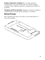
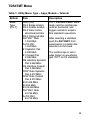
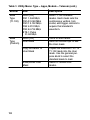
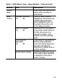
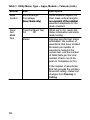
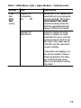
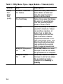
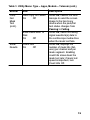
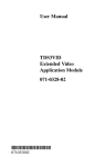
User Manual
TDS3TMT
Telecom Mask Test
Application Module
071-0648-02
*P071064802*
071064802
Copyright E Tektronix. All rights reserved. Licensed software
products are owned by Tektronix or its subsidiaries or suppliers,
and are protected by national copyright laws and international
treaty provisions.
Tektronix products are covered by U.S. and foreign patents,
issued and pending. Information in this publication supercedes
that in all previously published material. Specifications and
price change privileges reserved.
TEKTRONIX, TEK, TEKPROBE, and TekSecure are registered
trademarks of Tektronix, Inc.
DPX, WaveAlert, and e*Scope are trademarks of
Tektronix, Inc.
Contacting Tektronix
Tektronix, Inc.
14200 SW Karl Braun Drive
P.O. Box 500
Beaverton, OR 97077
USA
For product information, sales, service, and technical support:
H
H
In North America, call 1-800-833-9200.
Worldwide, visit www.tektronix.com to find contacts in
your area.
Contents
Safety Summary . . . . . . . . . . . . . . . . . . . . . . . . . . . . . 2
Installing the TDS3TMT Application Module . . . . . . . . 5
Telecom Mask Test Features . . . . . . . . . . . . . . . . . . . 5
Accessing TDS3TMT: QuickMenu . . . . . . . . . . . . . . . . 6
Accessing TDS3TMT: Utility Menu . . . . . . . . . . . . . . . 7
Conventions . . . . . . . . . . . . . . . . . . . . . . . . . . . . . . . 8
TDS3TMT Menu . . . . . . . . . . . . . . . . . . . . . . . . . . . . . 9
Telecom Pass/Fail Mask Test Example . . . . . . . . . . . . 24
1
Safety Summary
To avoid potential hazards, use this product only as
specified. While using this product, you may need to
access other parts of the system. Read the General Safety
Summary in other system manuals for warnings and
cautions related to operating the system.
Preventing Electrostatic Damage
CAUTION. Electrostatic discharge (ESD) can
damage components in the oscilloscope and its
accessories. To prevent ESD, observe these
precautions when directed to do so.
Use a Ground Strap. Wear a grounded antistatic wrist strap
to discharge the static voltage from your body while
installing or removing sensitive components.
Use a Safe Work Area. Do not use any devices capable of
generating or holding a static charge in the work area
where you install or remove sensitive components.
Avoid handling sensitive components in areas that have a
floor or benchtop surface capable of generating a static
charge.
2
Handle Components Carefully. Do not slide sensitive
components over any surface. Do not touch exposed
connector pins. Handle sensitive components as little as
possible.
Transport and Store Carefully. Transport and store sensitive
components in a static-protected bag or container.
Manual Storage
The oscilloscope front cover has a convenient place to
store this manual.
3
4
Installing the TDS3TMT Application Module
Refer to the TDS3000, TDS3000B, and TDS3000C
Series Application Module Installation manual for
instructions on installing and testing the application
module.
Telecom Mask Test Features
The TDS3TMT application module adds waveform
mask testing capabilities to your oscilloscope. This
section provides an overview of these additional features.
Telecom Mask Test QuickMenu
Use the telecom mask test QuickMenu function to
display bottom and side menus that provide access to all
key mask test functions from one screen.
Predefined Telecom Industry Masks
The TDS3TMT application module provides compliance
masks for testing to ITU-G.703 and ANSI T1.102
telecommunications standards, up to STS-1 (52 Mb/s)
line rates.
Multiple Channel Testing
The TDS3TMT application module enables you to
perform multiple simultaneous testing on all active
oscilloscope channels.
5
Test Automation
You can connect the oscilloscope to do automated mask
testing by using the RS--232, GPIB, or LAN communication ports.
Accessing TDS3TMT: QuickMenu
1. Push the QuickMenu front-panel button to display
the quick menu items.
2. Push the Menu bottom screen button to select and
display the Telecom bottom and side menu items.
3. Push bottom and side menu buttons to select a mask,
set test control parameters, and test pass/fail
responses.
6
Accessing TDS3TMT: Utility Menu
1. Push the UTILITY front-panel button to display the
utility menu items.
2. Push the System bottom screen button to display
Apps.
3. Push the Module bottom screen button to select
Telecom. The screen displays the telecom bottom and
side menu items.
4. Push bottom and side menu buttons to select a mask,
set test control parameters, and test pass/fail
responses.
7
Conventions
The following conventions apply to all TDS3TMT
functions:
H You can perform multiple waveform mask testing by
connecting signals to all oscilloscope input channels.
H While in Telecom Mask test mode, the AUTOSET
front-panel button automatically sets the oscilloscope
horizontal, vertical, and trigger parameters, and
positions the waveform in the selected mask.
H Mask testing only works with live channels. It is
recommended that you turn off math and reference
waveforms while doing mask testing.
8
TDS3TMT Menu
Table 1: Utility Menu: Type = Apps, Module = Telecom
Bottom
Side
Description
MaskType
(ITU-T)
None (Off)
DS-0 Single 64 kb/s
DS-0 Double 64 kb/s
DS-0 Data Contradirectional 64 kb/s
DS-0 Timing 64 kb/s
Old ”DS1” Rate
1.544 Mb/s
G.703 DS1
1.544 Mb/s
E1 Symetric Pair
2.048 Mb/s
E1 Coaxial Pair
2.048 Mb/s
Clk Interface Symetric
Pair 2.048 Mb/s
Clk Interface Coaxial
Pair 2.048 Mb/s
”DS2” Rate Symetric
Pair 6.312 Mb/s
”DS2” Rate Coaxial
Pair 6.312 Mb/s
E2 8.448 Mb/s
32.064 Mb/s
E3 34.368 Mb/s
Old ”DS3” Rate
44.736 Mb/s
G.703 DS3
44.736 Mb/s
ITU-T standard masks. Each
mask sets the oscilloscope
vertical, horizontal, and
trigger controls to acquire
that standard’s waveform.
After selecting a standard,
push the AUTOSET frontpanel button to position the
waveform in the mask.
The oscilloscope is set to
edge trigger on waveforms
(per ITU-T G.703 standard).
9
Table 1: Utility Menu: Type = Apps, Module = Telecom (cont.)
Bottom
Side
Description
Mask
Type
(T1.102)
None (Off)
DS1 1.544 Mb/s
DS1A 2.048 Mb/s
DS1C 3.152 Mb/s
DS2 6.312 Mb/s
DS3 44.736 Mb/s
STS-1 Pulse
51.84 Mb/s
ANSI T1.102 standard
masks. Each mask sets the
oscilloscope vertical, horizontal, and trigger controls to
acquire that standard’s
waveform.
Mask
Type
(Custom)
None (Off)
User Mask
Turns off user mask.
Sets the oscilloscope to use
the User mask.
Copy Std Mask To
User Mask
Copies the selected ITU-T or
T1.102 mask into the User
mask. Use the general purpose knob to select the
standard mask to load.
Save/Recall User
Mask
Saves or recalls User
masks.
10
Table 1: Utility Menu: Type = Apps, Module = Telecom (cont.)
Bottom
Side
Current
Mask
Mask
Control
Description
Status area that displays the
name of the currently selected mask.
Highlight Violations
On
Off
Stop On Violation
On
Off
Lock Mask To
Waveform
On
Off
Autofit Search Radius
Turns on mask violation
highlighting. Waveforms that
violate mask parameters
leave highlighted points on
the mask that are the color
of the failing waveform.
When set to On, the oscilloscope stops mask testing on
the first occurrence of a
waveform violation. This
function overrules pass/fail
tests.
Locks mask to waveform so
that the mask segments
move and redraw proportionally when changing the
horizontal or vertical scale or
position settings.
Autofit repositions the waveform using a spiral algorithm
to attempt to fit the waveform to a mask.
11
Table 1: Utility Menu: Type = Apps, Module = Telecom (cont.)
Bottom
Side
Description
Mask
Control
Vertical Margin
Percentage
(User mask only)
When enabled, adjusts the
User mask vertical margins
as a percent of the nominal
waveform amplitude for the
mask standard.
Pass/
Fail
Mask
Test
Pass/Fail Mask Test
On
Off
When set to On, resets the
status information and starts
mask testing.
Displays pass/fail test status
information: the number of
waveforms that have violated
the mask per number of
waveforms tested in the
current test, and the number
of failed tests per the total
number of tests run (if Repeat on Completion is On).
Status:
If the number of waveforms
that fail exceeds the violation
threshold setting, status text
changes from Passing to
Failing.
12
Table 1: Utility Menu: Type = Apps, Module = Telecom (cont.)
Bottom
Side
Description
Pass/
Fail
Mask
Test
(cont.)
Repeat On
Completion
On
Off
When set to On, repeats the
pass/fail test cycle using the
current settings. The status
area Failures/Test values
show how many times the
test has repeated and how
many of those tests failed.
Number Of
Waveforms
Sets the number of waveforms to acquire for each
pass/fail test cycle. Use the
general purpose knob to set
the value. Any value above
100,000 sets the waveform
count to infinity.
If waveform averaging is on,
the actual number of waveforms acquired is the Number Of Waveforms value
times the waveform averaging value.
13
Table 1: Utility Menu: Type = Apps, Module = Telecom (cont.)
Bottom
Side
Description
Pass/
Fail
Mask
Test
(cont.)
Violation Threshold
For Failure
Sets how many failed waveforms define a failed test.
Use the general purpose
knob to set the value.
Sets a time value that delays
the start of a pass/fail test.
Use the general purpose
knob to set the value.
Sets the polarity of all active
waveform channels. Values
are positive, negative, or
both. If set to Both, the
oscilloscope tests the first
half of all active channel
acquired waveforms in normal (uninverted) mode, and
then inverts all active channels and tests the second
half of acquired waveforms.
When On, causes the oscilloscope to emit a tone when
the pass/fail test is complete.
When On, causes the oscilloscope to emit a tone when
the pass/fail test status
changes from Passing to
Failing.
Pre-Test Delay
Polarity
Beep On Completion
On
Off
Beep On Failure
On
Off
14
Table 1: Utility Menu: Type = Apps, Module = Telecom (cont.)
Bottom
Side
Description
Pass/
Fail
Mask
Test
(cont.)
Hard Copy On Failure
On
Off
When On, causes the oscilloscope to send the screen
image to the hard copy
device when the pass/fail
test status changes from
Passing to Failing.
When On, saves the failing
signal waveform(s) data to
the oscilloscope media drive
when the mask test fails.
When On, displays the
number of mask hits (failures) per channel and per
mask segment. Enabling
count hits slows down the
mask test rate; if mask test
speed is important, turn
Count Hits Off.
Save Failed Wfm To
Disk
On
Off
Show
Results
Count Hits
On
Off
15
Table 1: Utility Menu: Type = Apps, Module = Telecom (cont.)
Bottom
Side
Description
Show
Results
Violations/
Waveforms, ...
Displays pass/fail test status
information: the number of
waveforms that have violated
the mask per number of
waveforms tested in the
current test, and the number
of failed tests per the total
number of tests run (if Repeat is On).
Segment 1 Hits
...
Segment 8 Hits
Status area that displays the
number of hits for each
channel on each mask segment.
Mask Testing and Pass/Fail Testing. Mask testing
means the detection and highlighting of mask segment
violations. Pass/Fail testing is setting conditions for mask
testing, such as the number of waveforms to test, how
many mask violations are allowed before failing a test,
whether to repeat testing upon completion, what action
to perform at the completion of a test, and so on.
Turn Off Mask Testing. To turn off mask testing and
remove the mask from the screen, set the mask standard
to None.
16
Standards and Pulse Amplitudes. For those cases
where a mask standard defines a valid pulse amplitude as
being within a range of values, the TDS3TMT mask is
drawn for the maximum permitted amplitude.
For those cases where a mask standard does not define
pulse amplitude, the TDS3TMT mask is drawn for a
nominal 1 V pulse.
Highlight Violations. Highlight Violations must be on in
order for the oscilloscope to perform mask comparisons.
If Highlight Violations is off, the oscilloscope will not
inform you of mask violations using highlighting or the
Stop On Violation command, and hits counting will not
count. Also, turning on pass/fail testing, Count Hits, or
Stop on Violation automatically turns on Highlight
Violations.
Pass/Fail Testing: Averaging. When averaging is on,
the oscilloscope first generates an averaged waveform,
then the averaged waveform is compared to the mask.
This means that the total number of waveforms acquired
is equal to the waveform averaging number times the
number of waveforms being tested. For example, if
pass/fail Number of Waveforms is set to 500, and
waveform averaging is set to 8, then the total number of
waveforms acquired for one pass/fail test cycle is
500 x 8 = 4,000.
17
Saving Waveforms to Disk. The default saved file name
is TEKnnnnn.fff, where nnnnn is an incrementing
number that usually starts at 00000, and fff is the file
format (Internal, Spreadsheet, or Mathcad file format) as
set in the SAVE/RECALL > Save Waveform to File
menu. For internal file format waveforms (.isf), if more
than one waveform is being tested, look at the .isf file
preamble information at the top of the file to determine
from which channel that waveform data came. Refer to
the TDS3000, TDS3000B, and TDS3000C Series
Programmer Manual for .isf file format information.
Proper Signal Termination. Make sure to correctly
terminate communication test signals. Tektronix offers
optional AMT75 adapters for correct communication
signal termination.
Pass/Fail Testing: Polarity. When polarity is set to both,
the oscilloscope tests the first half of all active channel
acquired waveforms with positive polarity, and then
inverts all active channels and tests the second half of
acquired waveforms.
Stop On Violation. If Stop On Violation is On, the
pass/fail status area displays Violation if there is a
violation, regardless of the pass/fail test settings. In other
words, Stop On Violation has a higher precedence than
pass/fail tests.
18
Running Mask Test Indefinitely. To run a mask test
indefinitely while counting the number of violations, set
Number of Waveforms to infinity (∞).
Triggering. Selecting a mask standard automatically sets
trigger parameters for that standard. However, to assign
specific trigger parameters to a mask (most likely for a
new User mask), push the Trigger MENU button,
selecting Comm, and selecting the mask standard to use
for triggering. The oscilloscope assigns the selected
standard’s trigger parameters to the current mask.
Testing For Infrequent Errors. To automatically capture
and save waveform violations that occur infrequently
over long periods of time, set Pass/Fail testing Repeat to
On, Number of Waveforms to 1, and Hardcopy/Wfm On
Failure to On. You may also want to set UTILITY >
Hard Copy > Options > Compression to ON to
compress the saved hardcopy data and thus store more
files on the floppy disk. Compression is not available for
waveform (*.isf) format data.
19
On-Screen Mask Positions. Many of the mask standards
have their mask drawn on the right side of the graticule
to allow enough room to the left for acquiring sufficient
serial trigger data.
When using the Lock Mask To Waveform feature, be
careful not to move the mask too far left or else you may
lose your serial trigger. Use Lock Mask To Waveform
after acquisitions have stopped to examine a mask
violation more closely.
To use Lock Mask to Waveform to make the mask fill
more of the screen, increase the acquisition record length
by pushing ACQUIRE > Horizontal Resolution >
Normal to set the record length to 10K points (note that
Normal mode only works with lock mode for horizontal
settings of 100 ns/div or faster). You can also use Zoom
to examine a mask and waveform, provided that you pan
and zoom in such a way that there is enough space to the
left of the mask for the oscilloscope to detect the serial
trigger.
20
Autofit Key Points. The following are some Autofit-specific key points:
H The Autofit radius defines the size of a square search
grid radius of (2 ¢ radius + 1) ¢ (2 ¢ radius + 1)
pixels, centered on the waveform position. Autofit
moves the waveform using a spiral pattern, testing for
mask violations at each position. For example, the
following table represents a spiral pattern for a radius
value of 2, where the number represents the order of
the waveform moves, and the position of the number
represents the position the waveform is offset relative
to the starting point (s). A radius of two attempts to fit
the waveform in 25 tries (start position plus 24).
9
24
23
22
21
10
1
8
7
20
11 12 13
2
3
14
s
4
15
6
5
16
19 18 17
H If pass/fail testing is used in conjunction with Autofit,
the Autofit center point is reset at the beginning of
each pass/fail test.
H Autofit is most appropriate when the waveform(s)
being tested is already close to fitting inside the mask.
21
H When Autofit moves the waveform, it only moves
the location where the waveform is drawn on the
display. It does not change any of the underlying
vertical, horizontal, or trigger parameters used to
acquire the waveform.
A consequence of this is that when moving the
waveform left (or right), the waveform points at the
right (or left) edge of the screen will be blank if the
horizontal settings are such that the entire acquired
waveform is displayed on screen. This is acceptable
because those points are typically outside the mask
region.
H If the waveform is a significant distance from the
mask, AUTOSET should be used first to adjust the
vertical, horizontal, and trigger parameters.
H When numerous waveforms are violating the mask
by substantial amounts, thereby causing Autofit to
run almost continuously, the instrument
responsiveness is significantly degraded. This is
another reason why AUTOSET is more appropriate
than Autofit for waveforms which violate the mask
by large amounts.
22
Automated Pass/Fail Testing Process. The recommended automated pass/fail testing process is:
1. Set the oscilloscope to default settings using the
SAVE/RECALL-->Recall Factory Setup menu.
2. Set the Graticule type to Frame
(DISPLAY-->Graticule menu).
3. Select the mask standard.
4. Turn off all waveforms not being tested.
5. Connect the appropriate input signals.
6. Push the Autoset button.
7. Set Autofit to a reasonably small value, such as 4.
8. Set Polarity to Both.
9. Set the number of Waveforms to 100.
10. Run the pass/fail test.
11. Note the pass/fail test status (Passed or Failed) and
take appropriate action.
12. Connect new signals.
13. Repeat from step 10.
23
Telecom Pass/Fail Mask Test Example
In this example, you want to test an ITU-T telecom
signal that needs to meet the E1 Coaxial Pair 2.048 Mb/s
standard. You want to highlight any waveform mask
errors, as well as set up pass/fail testing to test 500
waveforms, then stop.
Use the Telecom QuickMenu to set the TDS3TMT mask
parameters as listed in the table. Connect the signal to
CH 1 on the oscilloscope, then press the AUTOSET
front-panel button. After Autoset completes, press the
Run Test side menu button to perform the pass/fail test.
Telecom QuickMenu
Menu Item
Parameter
Value
Standard
Use buttons to scroll
through mask standard list
E1 Coax (ITU-T)
2.048 Mb/s
Control
Highlight
Average
Wfm Lock
Autofit
On
Off
Off
On (≥1)
24
Telecom QuickMenu (cont.)
Menu Item
Parameter
Value
Pass/Fail
Send hardcopy to
printer
Off (unchecked)
Send waveform to file
Beep on failure
Beep on completion
Repeat test
Waveforms
Threshold
Polarity
Off (unchecked)
On (checked)
On (checked)
Off (unchecked)
500
1
Positive
Use the upper menu button to select a response, and then
use the lower menu button to enable or disable the
selected response. You can select and enable any combination of responses.
25