1
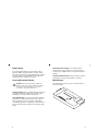
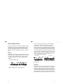
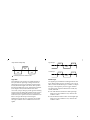
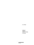
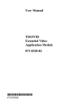
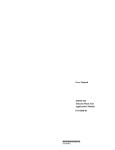
User Manual
TDS3TRG
Advanced Trigger
Application Module
071-0306-01
*P071030601*
071030601
Copyright © Tektronix, Inc. All rights reserved.
Tektronix products are covered by U.S. and foreign patents,
issued and pending. Information in this publication supercedes
that in all previously published material. Specifications and
price change privileges reserved.
Tektronix, Inc., P.O. Box 500, Beaverton, OR 97077
TEKTRONIX, TEK, TEKPROBE, and Tek Secure are
registered trademarks of Tektronix, Inc.
DPX, WaveAlert, and e*Scope are trademarks of
Tektronix, Inc.
WARRANTY SUMMARY
Tektronix warrants that the products that it manufactures and
sells will be free from defects in materials and workmanship
for a period of one (1) year from the date of shipment from an
authorized Tektronix distributor. If a product proves defective
within the respective period, Tektronix will provide repair or
replacement as described in the complete warranty statement.
To arrange for service or obtain a copy of the complete
warranty statement, please contact your nearest Tektronix sales
and service office.
EXCEPT AS PROVIDED IN THIS SUMMARY OR THE
APPLICABLE WARRANTY STATEMENT, TEKTRONIX
MAKES NO WARRANTY OF ANY KIND, EXPRESS OR
IMPLIED, INCLUDING WITHOUT LIMITATION THE
IMPLIED WARRANTIES OF MERCHANTABILITY AND
FITNESS FOR A PARTICULAR PURPOSE. IN NO EVENT
SHALL TEKTRONIX BE LIABLE FOR INDIRECT,
SPECIAL OR CONSEQUENTIAL DAMAGES.
Contacting Tektronix
Product
Support
For questions about using Tektronix measurement
products, call toll free in North America:
1-800-833-9200
6:00 a.m. – 5:00 p.m. Pacific time
Or contact us by e-mail:
[email protected]
For product support outside of North America,
contact your local Tektronix distributor or sales
office.
Service
Support
Tektronix offers a range of services, including
Extended Warranty Repair and Calibration
services. Contact your local Tektronix distributor or
sales office for details.
Contents
Safety Summary . . . . . . . . . . . . . . . . . . . . . . . . . . . .
Installing the Application Module . . . . . . . . . . . . . . .
Advanced Trigger Features . . . . . . . . . . . . . . . . . . . .
Accessing Advanced Triggering . . . . . . . . . . . . . . . .
Advanced Trigger Concepts . . . . . . . . . . . . . . . . . . .
Conventions . . . . . . . . . . . . . . . . . . . . . . . . . . . . . . .
Pattern Triggering . . . . . . . . . . . . . . . . . . . . . . . . . . .
State Triggering . . . . . . . . . . . . . . . . . . . . . . . . . . . . .
Pulse Width Triggering . . . . . . . . . . . . . . . . . . . . . . .
Runt Pulse Triggering . . . . . . . . . . . . . . . . . . . . . . . .
Slew Rate Triggering . . . . . . . . . . . . . . . . . . . . . . . . .
Specifications . . . . . . . . . . . . . . . . . . . . . . . . . . . . . .
2
5
5
7
8
14
15
17
19
22
25
28
For a listing of worldwide service centers, visit our
web site.
Toll-free
Number
In North America:
1-800-833-9200
An operator can direct your call.
Postal
Address
Tektronix, Inc.
Department or name (if known)
P.O. Box 500
Beaverton, OR 97077
USA
Web Site
www.tektronix.com
1
Safety Summary
To avoid potential hazards, use this product only as
specified. While using this product, you may need to
access other parts of the system. Read the General Safety
Summary in other system manuals for warnings and
cautions related to operating the system.
Preventing Electrostatic Damage
CAUTION. Electrostatic discharge (ESD) can
damage components in the oscilloscope and its
accessories. To prevent ESD, observe these
precautions when directed to do so.
Handle Components Carefully. Do not slide sensitive
components over any surface. Do not touch exposed
connector pins. Handle sensitive components as little as
possible.
Transport and Store Carefully. Transport and store sensitive
components in a static-protected bag or container.
Manual Storage
The oscilloscope front cover has a convenient place to
store this manual.
Use a Ground Strap. Wear a grounded antistatic wrist strap
to discharge the static voltage from your body while
installing or removing sensitive components.
Use a Safe Work Area. Do not use any devices capable of
generating or holding a static charge in the work area
where you install or remove sensitive components.
Avoid handling sensitive components in areas that have a
floor or benchtop surface capable of generating a static
charge.
2
3
Installing the Application Module
Please refer to the TDS3000 & TDS3000B Series
Application Module Installation Manual for information
on installing your application module.
Advanced Trigger Features
The TDS3TRG Advanced Trigger application module
adds logic and pulse triggering capabilities to your
TDS3000 series oscilloscope. This section provides an
overview of these new features.
Logic Trigger Features
Logic triggering triggers the oscilloscope when two
signals meet a Boolean logic condition. The advanced
trigger module provides pattern and state logic trigger
modes.
Pattern Trigger. Pattern triggering triggers the oscilloscope
when two signals become logically true or false. Basically, the pattern-triggering feature triggers the oscilloscope
from the output of a two-input AND, OR, NAND, or
NOR logic gate. You can specify time constraints and
signal threshold levels as part of the triggering condition.
This trigger is useful for digital logic troubleshooting.
4
5
State Trigger. State triggering triggers the oscilloscope
when a state signal is true or false at the time a clock
signal transition is true. This trigger is useful for troubleshooting digital logic synchronous state machines.
Pulse Trigger Features
Pulse triggering triggers the oscilloscope when a signal
meets a timing or threshold condition. The advanced
trigger module provides three pulse trigger modes: pulse
width, runt pulse, and slew rate.
Pulse Width. Pulse-width triggering triggers the oscilloscope when a signal pulse width is less than, greater
than, equal to, or not equal to a specified pulse width.
This trigger is useful for digital logic troubleshooting.
Slew Rate. Slew-rate triggering triggers the oscilloscope
when a signal’s slew rate (rise or fall time) is less than,
greater than, equal to, or not equal to a specified slew
rate. This trigger is useful for troubleshooting digital bus
transceivers, transmission lines, and op-amp circuits.
Accessing Advanced Triggering
1. Push the Trigger MENU button to display the Trigger
screen buttons.
2. Push the Type bottom screen button to display the
trigger type pop-up menu.
3. Push the Type bottom screen button to select Logic or
Pulse triggering.
4. Push the Class screen button to select trigger class.
Runt Pulse. Runt-pulse triggering triggers the oscillo-
scope when a signal pulse is less than a specified threshold level. You can also specify runt pulse-width parameters. This trigger is useful for troubleshooting
bus-contention problems.
6
7
Advanced Trigger Concepts
This section introduces the concepts of signal logic and
thresholds as they relate to advanced triggering. These
concepts apply to most or all of the advanced trigger
functions. You should read this section if you are not
familiar with advanced triggering concepts or Boolean
logic.
Overview
Edge triggering can trigger on most signals, and is the
default trigger type. Edge triggering sets the oscilloscope
to trigger (acquire signal data) when a signal meets a
specified signal slope and a single voltage-threshold
condition.
However, there are times when you need to trigger the
oscilloscope on a more complex signal, or when two
signals meet a condition, in order to troubleshoot a
particular problem. These problems include a pulse that
is too narrow or wide, and situations in which one signal
is true when a second signal transitions from low to high.
Advanced triggering can help acquire signals with these
types of problems. Advanced triggering lets you further
qualify the trigger conditions by adding parameters such
as pulse width, delta time, logical comparisons of two
signals, and dual threshold levels.
Pulse width
Runt pulse
Single threshold voltage setting
= Trigger point
Thresholds
= Possible trigger points for positive slope signals
8
Both pulse and logic triggering trigger the oscilloscope
when one or two signals are logically true. To determine
whether a signal is true or false, you must set a signal
reference point that determines whether a signal is in one
of two states. You set this reference point by specifying a
threshold voltage level for each trigger signal. Crossing
the threshold level toggles the state value of that signal.
9
High-true logic
Single threshold voltage setting
True
True
False
High logic
state
Low logic
state
Low logic
state
Low-true logic
False
False
True
= Transition point from one state to another
Logic State
Boolean Logic
The actual state (true or false) of a signal depends on
how you define its signal logic setting, which can be
either high-true or low-true. Defining a signal as hightrue (H) means that signal levels above (more positive
than) the threshold level are true, and signal levels below
(more negative than) the threshold level are false.
A low-true (L) logic setting is just the opposite. Defining
a signal as low-true means that signal levels below (more
negative than) the threshold level are true, and signal
levels above (more positive than) the threshold level are
false. Low logic effectively inverts the signal.
Defining the logical state of a signal lets you use Boolean logic to evaluate when a condition is true for two
signals.
The signal logic (threshold level and high-true/low-true
logic) defines which part of a waveform cycle is true or
false. You then use Boolean logic to evaluate or compare
the logic of two signals as part of a trigger condition.
The four logical comparison functions are AND, OR,
NAND, and NOR:
H The AND function means that if both signal logic
states are true, the condition is true, otherwise the
condition is false.
10
H The OR function means if either or both signal logic
states are true, the condition is true, otherwise the
condition is false.
11
H The NAND (Not-AND) function means that if both
signal logic states are true, the condition is false,
otherwise the condition is true. This function is the
inverse of the AND function.
H The NOR (Not-OR) function means if any or all of
the trigger signal logic states are true, the condition is
false, otherwise the condition is true. This function is
the inverse of the OR function.
Remember that the logic function evaluates the logic
states of two signals, and that the logic state of each
signal depends on whether they are set to high-true or
low-true logic.
For example, assume that you want to trigger the oscilloscope only when signal one is low at the same time that
signal two is high. Therefore you want to:
H Set a threshold level that is appropriate for each
signal.
H Set signal one to be true when it is low (low-true
signal logic).
12
H Set signal two to be true when the signal is high
(high-true signal logic).
H Trigger when both conditions are true (AND trigger
logic).
Trigger logic: Signal 1 AND Signal 2
Signal 1 logic = low true
Threshold
settings
Signal 2 logic = high true
Pattern is true: trigger
The material you have just read provides a basic understanding of the triggering concepts you need in order to
use the Logic and Pattern triggering functions. Refer to
the Reference section for detailed information about the
advanced trigger functions.
13
Conventions
Pattern Triggering
The following conventions apply to all advanced trigger
functions:
H You cannot use any of the advanced trigger functions
to arm B triggering.
Pattern Trigger Conditions
H You do not have to display a channel in order to use
the channel as a trigger source.
H The range of time values for pulse width (regular and
runt) and slew rate is from 39.6 ns to 10 s.
H In the menu tables, N represents a numeric value
entered using the general purpose knob.
Define Inputs Thresholds
H
Define logic
AND
Input 1
L
H
OR
Trigger when
Goes true/false
Delta time
Trigger
NAND
Input 2
NOR
L
True
<,>,=,0time
Pattern Trigger Menu
Table 1: Trigger Menu: Type = Logic, Class = Pattern
Bottom
Side
Description
Define Inputs
Input 1
Source
Sets the pattern trigger signal
input 1 source.
Logic
Sets the signal logic for input 1.
H = high true, L = low true.
Input 2
Source
Sets the pattern trigger signal
input 2 source.
Logic
Sets the signal logic for input 2.
H = high true, L = low true.
AND, OR,
NAND, NOR
Sets which logic function to
apply to the input signals.
Define Logic
14
15
Table 1: Trigger Menu: Type = Logic, Class = Pattern (cont.)
Bottom
Side
Description
Trigger When
Goes True/
Goes False
Triggers the oscilloscope when
the logic condition is true or
false.
Triggers the oscilloscope when
the input logic condition is true
for a time period greater than or
less than time period N.
Is True < N
Is True > N
Is True = N
Is True 0 N
Thresholds
Level
(Input 1) N
Level
(Input 2) N
Mode &
Holdoff
Triggers the oscilloscope when
the input logic condition is true
for a time period equal to or not
equal to time period N within a
±5% tolerance.
Sets the threshold voltage level
for input 1 and 2 to level N,
using the general purpose knob.
Set to TTL
Sets the threshold voltage level
to 1.4 V for both inputs.
Set to ECL
Sets the threshold voltage level
to –1.3 V for both inputs.
Set to 50%
Sets the threshold voltage level
to 50% of each input’s peak-topeak value.
Same as Edge Trigger.
State Triggering
State Trigger Conditions
Define
inputs
Thresholds
H
Trigger when
S
State
Q
L
Q
C
True
Trigger
False
Clock
State Trigger Menu
Table 2: Trigger Menu: Type = Logic, Class = State
Bottom
Side
Description
Define Inputs
State Input
Source
Sets the state signal source.
Logic
Sets the signal logic for state
input source.
H = high true, L = low true.
Sets the clock signal source.
Clock Input
Source
Slope
Sets the signal slope (rising or
falling) for clock input. The clock
slope defines when the clock
signal is true.
Trigger When. The input condition must be true or false
for ≥2 ns in order for the oscilloscope to detect the
pattern.
16
17
Table 2: Trigger Menu: Type = Logic, Class = State (cont.)
Bottom
Side
Description
Trigger When
Goes True
Triggers the oscilloscope if the
state signal is true when the
clock signal slope is true.
Triggers the oscilloscope if the
state signal is false when the
clock signal slope is true.
Sets the threshold voltage level
for state and clock signals to
level N, using the general
purpose knob.
Goes False
Thresholds
Mode &
Holdoff
Level
(State Input)
N
Level
(Clock Input)
N
Set to TTL
Pulse Width Triggering
Pulse Trigger Conditions
Triggers when pulse is
less than width setting
Triggers when pulse is
greater than width setting
Threshold level
riggers when pulse is equal
to width setting ± 5%
Triggers when pulse is not
equal to width setting ± 5%
Sets the threshold voltage level
to 1.4 V for both inputs.
Set to ECL
Sets the threshold voltage level
to –1.3 V for both inputs.
Set to 50%
Sets the threshold voltage level
to 50% of each input’s peak-topeak value.
Same as Edge Trigger.
Threshold level
Tolerance
Tolerance
= Trigger point
Trigger When. The state signal must be true or false for
≥2 ns prior to the clock transition in order for the oscilloscope to detect the state.
18
19
Table 3: Trigger Menu: Type = Pulse, Class = Width (cont.)
Pulse Width Trigger Menu
Table 3: Trigger Menu: Type = Pulse, Class = Width
Bottom
Side
Description
Source
Ch1 - Ch4
Sets the pulse width signal
source.
Sets external or external divided
by 10 as the signal source.
Ext
Ext/10
AC Line
Vert
Polarity
Positive
Negative
Trigger When
Pulse Width
<N
Pulse Width
>N
Pulse Width
=N
Pulse Width
0N
20
Sets the AC line frequency as
the trigger source. This trigger
source is only available when
the oscilloscope is connected to
AC power.
Sets the lowest-numbered
displayed channel as the trigger
source.
Sets the source signal pulse
polarity on which to trigger.
Bottom
Side
Description
Level
Level N
Sets the signal threshold voltage level to N using the general
purpose knob.
Sets the signal threshold voltage level to 1.4 V.
Set to TTL
Mode &
Holdoff
Set to ECL
Sets the signal threshold voltage level to –1.3 V.
Set to 50%
Sets the threshold voltage level
to 50% of the signal’s peak-topeak value.
Same as Edge Trigger
Trigger When. The source pulse width must be ≥5 ns in
order for the oscilloscope to detect the pulse.
Triggers the oscilloscope when
the source signal pulse width is
less than or greater than the
specified pulse width N.
Triggers the oscilloscope when
the signal pulse width is equal
to or not equal to the specified
pulse width N within a ±5%
tolerance.
21
Runt Pulse Triggering
Runt Pulse Trigger Menu
Table 4: Trigger Menu: Type = Pulse, Class = Runt
Trigger Conditions
Any runt
(positive, negative, or
either)
Bottom
Side
Description
Source
Ch1 - Ch4
Ext
Ext/10
AC Line
Vert
Positive
Negative
Either
Runt Occurs
Sets the runt signal source.
Sets external or external divided
by 10 as the signal source.
Polarity
Runt is less than
width setting
Runt is greater than
width setting
Trigger When
Runt Width
<N
Runt is equal to width
setting ± 5% tolerance
Runt is not equal to width
setting ± 5% tolerance
Runt Width
>N
Runt Width
=N
Runt Width
0N
Tolerance
Same as description on
page 20.
Sets the source signal runt
pulse polarity on which to
trigger.
Triggers the oscilloscope when
any runt pulse is detected,
regardless of width.
Triggers the oscilloscope when
the runt signal pulse width is
less than or greater than the
specified pulse width N.
Triggers the oscilloscope when
the runt signal pulse width is
equal to or not equal to the
specified pulse width N within a
±5% tolerance.
Tolerance
= Trigger point
22
23
Table 4: Trigger Menu: Type = Pulse, Class = Runt (cont.)
Bottom
Side
Description
Thresholds
High N
Sets the runt signal high threshold and low threshold voltage
levels to value N, using the
general purpose knob.
Low N
Set to TTL
Set to ECL
Mode &
Holdoff
Sets runt signal threshold
voltage levels to 2.0 V (high
threshold) and 0.8 V (low
threshold).
Sets runt signal threshold
voltage levels to –1.1 V (high
threshold) and –1.5 V (low
threshold).
Same as Edge Trigger
Trigger When. The source runt pulse width must be ≥5 ns
in order for the oscilloscope to detect the pulse.
Slew Rate Triggering
Slew Rate Trigger Conditions
Signal slew rate is greater
(faster) than specified slew rate
Specified slew rate
Actual slew rate
Signal slew rate is equal
to specified slew rate
±5% tolerance
Tolerance
Signal slew rate is less (slower
than specified slew rate
Specified slew rate
Actual slew rate
Signal slew rate is not
equal to specified slew rate
±5% tolerance
Tolerance
= Trigger point
24
25
Slew Rate Trigger Menu
Table 5: Trigger Menu: Type = Pulse, Class = Slew Rate (cont.)
Table 5: Trigger Menu: Type = Pulse, Class = Slew Rate
Bottom
Side
Description
Source
Ch1 - Ch4
Sets the slew rate signal
source.
Sets external or external divided
by 10 as the signal source.
Polarity
Trigger When
Ext
Ext/10
AC Line
Vert
Positive
Negative
Either
Slew Rate < N
Slew Rate > N
Slew Rate
=N
Slew Rate
0N
Delta Time
N
26
Bottom
Side
Description
Thresholds
High N
Sets the signal high threshold
and low threshold voltage level
components of the slew rate to
value N, using the general
purpose knob.
Low N
Set to TTL
Same as description on
page 20.
Sets the source signal slew rate
polarity on which to trigger.
Triggers the oscilloscope when
the signal slew rate is less than
or greater than the specified
slew rate N.
Triggers the oscilloscope when
the signal slew rate is equal to
or not equal to the specified
slew rate N within a ±5% tolerance.
Shows the delta time component N of the slew rate, as set
using the general purpose knob.
Set to ECL
Mode &
Holdoff
Sets the signal threshold voltage levels to 2.0 V (high
threshold) and 0.8 V
(low threshold).
Sets the signal threshold voltage levels to –1.1 V (high
threshold) and –1.5 V
(low threshold).
Same as Edge Trigger
Delta Time and Thresholds. The delta time and threshold
settings determine the calculated slew rate (volts ÷ time).
Changing either value changes the calculated slew rate.
Trigger When. The delta time component of the slew rate
(time from threshold to threshold) must be ≥5 ns in order
for the oscilloscope to detect the slew rate.
27
Specifications
Table 6: TDS3TRG specifications (cont.)
This section describes the TDS3TRG Advanced Trigger
application module specifications. All specifications are
guaranteed unless labeled ”typical.” Typical specifications are provided for your convenience but are not
guaranteed.
To meet specifications, two conditions must first be met:
H The oscilloscope must have been operating
continuously for ten minutes within the operating
temperature range specified.
H You must perform the Compensate Signal Path
operation described in the oscilloscope user manual.
If the operating temperature changes by more than
10° C, you must perform the Compensate Signal Path
operation again.
Table 6: TDS3TRG specifications
Characteristic
Description
Logic and Pulse
Trigger Sensitivity, typical
1.0 division at BNC, DC Coupled, ≥10 mV/div
to ≤ 1 V/div
(pattern, state, delay, width, and runt triggering)
Same as Edge Trigger Sensitivity specifications in the oscilloscope user manual.
Slew Rate Trigger Sensitivity,
typical
28
Characteristic
Description
Logic Triggering
Minimum Logic
Time, typical
Pattern
State
2 ns
2 ns
Pattern minimum logic time: the time that a
logic pattern must be valid to be recognized.
State minimum logic time: the time that a logic
state must be valid before and after the clock
edge to be recognized.
Logic Triggering
Minimum Rearm
Time, typical
Pattern
State
2 ns
4 ns
Pattern minimum rearm time: the time that a
logic pattern must be invalid before a new
occurrence of the pattern is recognized.
State minimum rearm time: the time between
consecutive clocks.
Pulse Triggering
Minimum Pulse
Width, typical
5 ns
For pulse and runt, minimum pulse width
refers to the pulse being measured.
For slew rate, minimum pulse width means the
minimum delta time that the oscilloscope
recognizes.
29
Table 6: TDS3TRG specifications (cont.)
Characteristic
Description
Pulse Triggering
Minimum Rearm
Time, typical
5 ns
For pulse and runt, rearm time refers to the
time between measured pulses.
For slew rate, rearm time refers to the time it
takes the signal to recross the two signal
thresholds.
Time Range
Resolution
39.6 ns to 9.99 ms
13.2 ns
10 ms to 99.9 ms
92.4 ns
100 ms to 999 ms
1 ms
1 ms to 9.99 ms
10 ms
10 ms to 99.9 ms
100 ms
100 ms to 999 ms
1 ms
1 s to 10 s
10 ms
Delta Time
Resolution using
general purpose
knob
30