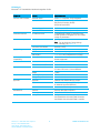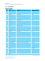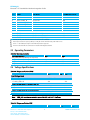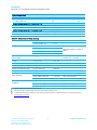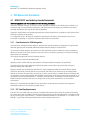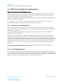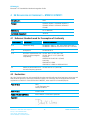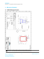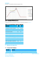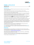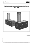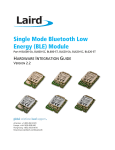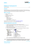
1
BTM410/411 DATA MODULE Hardware Integration Guide Version 6.3 Americas: +1-800-492-2320 Option 2 Europe: +44-1628-858-940 Hong Kong: +852-2923-0610 [email protected] www.lairdtech.com/bluetooth BTM410/411 Bluetooth® AT Data Module Hardware Integration Guide REVISION HISTORY Revision Date Description 1.0 1 March 2012 Initial Release 2.0 12 March 2012 General updates and compliant with firmware v16.1.3.0 3.0 13 April 2012 Reformatting and general edits 4.0 15 August 2012 Reformatting. Addition of Table 2-6. Reference to Table 2-6 in Table 2-1. Update to Sniff Mode section (everything following Figure 5). Cross References. Updated ATI Commands table. Added links to Low Power and Absolute Current Ratings application notes. 5.0 21 March 2013 Updated mechanical drawings, updated FCC statements, general formatting edits. 6.0 16 January 2014 Separated document into two documents: Hardware Integration Guide and User Guide 6.1 06 Feb 2014 6.2 07 August 2014 6.3 3 Sept. 2014 Americas: +1-800-492-2320 Option 2 Europe: +44-1628-858-940 Hong Kong: +852-2923-0610 www.lairdtech.com/bluetooth Added the Bluetooth SIG Qualification section. Updated shipping tray image and added module package dimension image. Updated EU Declaration of Conformity 2 CONN-HIG-BTM410-411 BTM410/411 Bluetooth® AT Data Module Hardware Integration Guide CONTENTS Revision History .............................................................................................................................................. 2 Contents ........................................................................................................................................................ 3 1. Overview and Key Features ...................................................................................................................... 4 2. Specifications ........................................................................................................................................... 5 2.1 Detailed Specifications ....................................................................................................................... 5 2.2 Pin Definitions ................................................................................................................................... 7 2.3 Operating Parameters ........................................................................................................................ 8 2.4 Voltage Specifications ........................................................................................................................ 8 3. FCC Regulatory Statements .................................................................................................................... 10 4. Declarations of Compliance ......................................................................... Error! Bookmark not defined. 5. Mechanical Drawings ............................................................................................................................. 13 5.1 BTM410 Mechanical Details............................................................................................................. 13 5.4 BTM411 Mechanical Details............................................................................................................. 16 6. Application Note for Surface Mount Modules ........................................................................................ 20 6.1 Introduction .................................................................................................................................... 20 6.2 Shipping .......................................................................................................................................... 20 6.3 Reflow Parameters ........................................................................................................................... 21 7. Ordering Information ............................................................................................................................. 22 7.1 Product Part Numbers ...................................................................................................................... 22 7.2 General Comments ......................................................................................................................... 23 8. Bluetooth SIG Qualification .................................................................................................................... 23 8.1 Additional Assistance....................................................................................................................... 24 9. Related Documents and Files .................................................................................................................. 25 Americas: +1-800-492-2320 Option 2 Europe: +44-1628-858-940 Hong Kong: +852-2923-0610 www.lairdtech.com/bluetooth 3 CONN-HIG-BTM410-411 BTM410/411 Bluetooth® AT Data Module Hardware Integration Guide 1 OVERVIEW AND KEY FEATURES The BTM410 and BTM411 Bluetooth® modules from Laird are designed to meet the needs of developers who wish to add robust, short range Bluetooth data connectivity to their products. These modules are based on the market leading Cambridge Silicon Radio BC04 chipset, providing exceptionally low power consumption with outstanding range. They support the Bluetooth® version 2.1 specification, providing the important advantage of Secure Simple Pairing (SSP), which improves security and ease of use for end customers. With physical sizes as small as 12.5 mm x 18.0 mm and best of class, low-power operation, these modules are the ideal choice for applications where designers need both performance and minimum size. For maximum flexibility in systems integration, the modules are designed to support a separate power supply for I/O. To aid product development and integration, Laird has integrated a complete Bluetooth protocol stack within the modules, including support for the Bluetooth Serial Port Profile. The modules are fully qualified as Bluetooth End Products, allowing designers to integrate them within their own products with no further Bluetooth Qualification. They can then list and promote products on the Bluetooth website free of charge. A comprehensive AT command interface is included, which simplifies firmware integration. Combined with a low cost developer’s kit, choosing Laird Bluetooth modules guarantees the fastest route to market. Features and Benefits Applications Bluetooth® v2.1+EDR Adaptive Frequency Hopping to handle interference from other wireless devices Secure Simple Pairing (SSP) support External or internal antenna options Comprehensive AT interface for simple programming Bluetooth® End Product Qualified Compact size Class 2 output – 4 dBm Low power operation UART interface PCM and SCO for external codec GPIO lines under AT control Wi-Fi co-existence Americas: +1-800-492-2320 Option 2 Europe: +44-1628-858-940 Hong Kong: +852-2923-0610 www.lairdtech.com/bluetooth 4 Embedded devices Phone accessories Security devices Medical and wellness devices Automotive applications Bluetooth advertising ePOS CONN-HIG-BTM410-411 BTM410/411 Bluetooth® AT Data Module Hardware Integration Guide 2 SPECIFICATIONS 2.1 Detailed Specifications Table 2-1: Detailed specifications Categories Wireless Specification Feature Bluetooth Implementation ® Version 2.1+EDR Transmit Class Class 2 Frequency 2.402 – 2.480 GHz Channels 79 channels Frequency Hopping Adaptive Frequency Hopping Max. Transmit Power +4 dBm at antenna pad – BTM410 +4 dBmi from integrated antenna – BTM411 Min. Transmit Power -27 dBm at antenna pad – BTM410 -27 dBmi from integrated antenna – BTM411 Receive Sensitivity -84 dBm Range 30 m Data Transfer Rate Up to 300 kbps External Antenna 50 Ohm matched SMT pad – BTM410 Integrated Antenna (option) +0 dBi multilayer ceramic – BTM411 Serial Interface RS-232 bi-directional for commands and data 16550 compatible Baud Rate Configurable from 1,200 to 921,600 bps Non-standard baud rates supported Bits 8 Parity Odd, even, none Stop bits 1 or 2 Default Serial parameters 9600,n,8,1 Levels Set by VDD_USB input Modem Control DTR, DSR, DCD, RI, RTS, CTS General Purpose Interface I/O 8 general purpose I/O pins Audio Support 1 PCM channel @ 64 kbps SCO Channels Support SCO and eSCO PCM Interface Configurable as master or slave 8 bit A-law 8 bit μ-law 13 bit linear PCM Clock available when in slave mode Antenna Modes UART Interface Americas: +1-800-492-2320 Option 2 Europe: +44-1628-858-940 Hong Kong: +852-2923-0610 www.lairdtech.com/bluetooth 5 CONN-HIG-BTM410-411 BTM410/411 Bluetooth® AT Data Module Hardware Integration Guide Categories Feature Implementation Protocols And Firmware Bluetooth Stack Version 2.1 compliant. Fully integrated. Profiles GAP (Generic Access Profile) SDP (Service Discovery Profile) SPP (Serial Port Profile) Firmware Upgrade Available over UART Connection Modes Point to point (cable replacement) Command Interface AT Instructions set Comprehensive control of connection and module operation S Registers for non-volatile storage of parameters Current Consumption Data Transfer Typically 32 mA Note: For an Absolute Current Ratings summary, see Table 2-6. Low Power Sniff Mode Less than 2.5mA Supply 3.0 V – 3.3 V DC I/O 1.7 V – 3.3 V DC (independent of Supply) USB & UART 1.7 V – 3.6 V DC (independent of Supply) Coexistence/ Compatibility WLAN (802.11) 2-wire and 3-wire hardware coexistence schemes supported Connections Interface Surface Mount Pads External Antenna (BTM410) Pad for 50 Ohm antenna Dimensions 12.5 mm x 18.0 mm x 3.4 mm BTM410 12.5 mm x 22.0 mm x 3.4 mm BTM411 Weight 3 grams Operating Temperature -40° C to +85° C Storage Temperature -40° C to +85° C Bluetooth Qualified as an Bluetooth End product FCC Limited Modular Approval (BTM410) Full Modular Approval (BTM411) CE & R&TTE Meets CE and R&TTE requirements Lead free Lead-free and RoHS compliant Warranty 5-Year Limited Lifetime Development Kit Development board and software tools DVK-BTM410 Dev Kit with BTM410 module DVK-BTM411 Dev Kit with BTM411 module Supply Voltage Physical Environmental Approvals Miscellaneous Development Tools Americas: +1-800-492-2320 Option 2 Europe: +44-1628-858-940 Hong Kong: +852-2923-0610 www.lairdtech.com/bluetooth 6 CONN-HIG-BTM410-411 BTM410/411 Bluetooth® AT Data Module Hardware Integration Guide 2.2 Pin Definitions Table 2-2: Pin definitions Pin # 1 2 3 4 5 6 7 8 9 10 11 12 13 14 15 16 17 18 19 20 21 22 23 24 25 26 27 28 29 30 31 32 33 34 35 36 37 38 39 Signal Unused GND UART_CTS UART_RXD UART_RTS UART_TXD GND SPI_CSB SPI_MISO SPI_MOSI SPI_CLK VDD_USB VDD_IO VDD_IN GND PCM_IN PCM_SYNC PCM_CLK PCM_OUT RESET GPIO4 GPIO2 / UART_DCD GND Unused Unused Unused Unused GND (BTM410 only) ANT (BTM410 only) GND (BTM410 only) Unused Unused Unused Unused Unused Unused Unused Unused Unused Americas: +1-800-492-2320 Option 2 Europe: +44-1628-858-940 Hong Kong: +852-2923-0610 www.lairdtech.com/bluetooth Description Voltage Specification Clear to Send I/P Receive data I/P Request to Send O/P Transmit data O/P VUSB VUSB VUSB VUSB SPI bus chip select I/P SPI bus serial O/P SPI bus serial I/P SPI bus clock I/P USB & UART supply voltage I/O supply voltage Main supply voltage VIO VIO VIO VIO PCM data I/P PCM sync I/P PCM clock I/P PCM data O/P Module reset I/P I/O for host - BT_Active / BT_State I/O for host VIO VIO VIO VIO See note 2 VIO VIO Antenna connection (50 ohm matched) 7 See note 3 See note 3 See note 3 See note 3 See note 3 See note 3 See note 3 See note 3 See note 3 See note 3 See note 3 See note 3 See note 3 CONN-HIG-BTM410-411 BTM410/411 Bluetooth® AT Data Module Hardware Integration Guide Pin # 40 41 42 43 44 45 46 47 48 49 50 Signal Unused GND GPIO1 / UART_RI GPIO7 / UART_ DTR GPIO8 / UART_DSR GND DD+ GPIO6 GPIO5 GPIO3 Description Voltage Specification I/O for host I/O for host I/O for host VIO VIO VIO Not used for AT module variants Not used for AT module variants I/O for host - RF_Active I/O for host - WLAN_Active I/O for host - BT_Priority VUSB VUSB VIO VIO VIO Unused pins may have internal connections and must not be connected. Reset input is active low. Input is pulled up to VDD_IN via 22k. Minimum reset pulse width is 5 ms. Pins 8 – 11 (SPI related) are only for Laird internal production purposes. Pins 25-37 should be left not connected on modules with integrated antenna. 2.3 Operating Parameters Table 2-3: Operating parameters Operating Condition VDD_USB (USB compatibility not required) VDD_USB (USB compatibility required) VDD_IO VDD_IN Min 1.7 3.1 1.7 3.0 Max 3.6 3.6 3.3 3.3 2.4 Voltage Specifications Table 2-4: Voltage specifications (VUSB) Min Typ Max Input Voltage Levels Vih Vil 2.7<VDD_USB<3.0 1.7<VDD_USB<1.9 Output Voltage Levels (1.7<VDD_USB<1.9) Voh (Iout = -4mA) Vol (Iout = 4mA) Output Voltage Levels (2.7<VDD_USB<3.0) Voh (Iout = -4mA) Vol (Iout = 4mA) Note: 0.7VDD_USB -0.4 -0.4 +0.8 -0.4 VDD_USB – 0.4 0.4 VDD_USB – 0.2 0.2 VDD_USB must be connected to power the USB and UART interfaces. Table 2-5: Voltage specifications (VIO) Min Americas: +1-800-492-2320 Option 2 Europe: +44-1628-858-940 Hong Kong: +852-2923-0610 www.lairdtech.com/bluetooth 8 Typ Max CONN-HIG-BTM410-411 BTM410/411 Bluetooth® AT Data Module Hardware Integration Guide Input Voltage Levels Vih Vil 2.7<VDD_USB<3.0 1.7<VDD_USB<1.9 Output Voltage Levels (1.7 < VDD_IO < 1.9) Voh (Iout = -4 mA) Vol (Iout = 4 mA) Output Voltage Levels (2.7 < VDD_IO < 3.0) Voh (Iout = -4 mA) Vol (Iout = 4 mA) 0.7VDD_IO -0.4 -0.4 +0.8 -0.4 VDD_USB – 0.4 0.4 VDD_USB – 0.2 0.2 Table 2-6: Absolute Current Rating Summary Power up / reset I_avg_reset 20.7 mA t_reset_current_dur. 3.0 s I_avg @ 9600 baud 2.60 mA I_avg @ 38400 baud 2.75 mA I_avg @ 115200 baud 2.95 mA I_avg @ 460800 baud 4.37 mA Connectable and Discoverable I_avg_cycle 23.1 mA Inquiry I_avg_inquiry 42.1 mA Initiate pairing I_avg_pair_ini 28.8 mA Accept pairing I_avg_pair_acc 42.0 mA Initiate a connection (SPP) I_avg_connect_ini 39.8 mA Accept a connection (SPP) I_avg_connect_ini 37.2 mA Connected as master, no data exchange I_avg_conn_master_idle 13.3 mA Active mode I_avg_master_sniff_idle 13.6 mA Sniff interval=50 ms I_avg_master_ssr_idle 9.9 mA SSR, interval=300 ms I_avg_conn_slave_idle 29.0 mA Active mode I_avg_slave_sniff_idle 12.7 mA Sniff interval=50 ms I_avg_slave_ssr_idle 9.9 mA SSR, interval=300 ms Idle(2) Connected as slave, no data exchange 5 second average, no data at UART(2) AT+BTP / ATS512=4, 9600 Baud, average over 1 interval All current peaks measured were less than 86 mA. Even when no data transmits, higher baud rates cause a higher standby current. For additional information on Absolute Current Rating, see Application Note – BTM41x Absolute Current Ratings located at www.lairdtech.com/wireless. Americas: +1-800-492-2320 Option 2 Europe: +44-1628-858-940 Hong Kong: +852-2923-0610 www.lairdtech.com/bluetooth 9 CONN-HIG-BTM410-411 BTM410/411 Bluetooth® AT Data Module Hardware Integration Guide 3 FCC REGULATORY STATEMENTS 3.1 BTM410 FCC and Industry Canada Statements The Final Equipment user manual must show the following statements: This device complies with part 15 of the FCC Rules. Operation is subject to the following two conditions: (1) This device may not cause harmful interference, and (2) this device must accept any interference received, including interference that may cause undesired operation. Changes or modifications not expressly approved by the party responsible for compliance could void the user’s authority to operate the equipment. To comply with the FCC RF exposure compliance requirements, this device and its antenna must not be co-located or operating to conjunction with any other antenna or transmitter. 3.1.1 Considerations for OEM Integration This module has a limited modular approval. Approval with any other antenna configuration or layout other than that approved will necessitate additional radiated emission testing to be performed. To inherit the modular approval, the antennas for this transmitter must be installed to provide a separation distance of at least 20 cm from all persons and must not be co-located or operating in conjunction with any other antenna or transmitter. This module was approved with the following antenna: RF Solutions: ANT-24G-WHJ-SMA 0dBi Operation of this module with any other antenna will require additional testing to be performed. Co-location with other radio transmitting devices operating concurrently in the same band will require additional testing and certification. Designers should note the distinction that the FCC makes regarding portable and mobile devices. Mobile devices are defined as products that are not used closer than 20cm to the human body, whereas portable devices can be used closer that 20cm to the body. A device may be used in portable exposure conditions with no restrictions on host platforms when the averaged output power is less than the low power threshold for an uncontrolled environment ≤ 60/f(GHz) i.e. 25mW for a 2.4Ghz device. The Maximum Power Exposure for the BTM410 has been evaluated and found to comply with the low power threshold for an uncontrolled environment. Refer to FCC document KDB 447498 for more information on RF exposure procedures and equipment authorization policies for mobile and portable devices. 3.1.2 FCC Labelling Requirement If the FCC ID is not visible when the module is installed inside another device, then the outside of the device into which the module is installed must also display a label referring to the enclosed module. This exterior label can use wording such as the following: “Contains Transmitter Module FCC ID: PI4410B” or “Contains FCC ID: PI4410B.” Any similar wording that expresses the same meaning may be used. Americas: +1-800-492-2320 Option 2 Europe: +44-1628-858-940 Hong Kong: +852-2923-0610 www.lairdtech.com/bluetooth 10 CONN-HIG-BTM410-411 BTM410/411 Bluetooth® AT Data Module Hardware Integration Guide 3.2 BTM411 FCC and Industry Canada Statements The user manual must show the following statements: This device complies with part 15 of the FCC Rules. Operation is subject to the following two conditions: (1) This device may not cause harmful interference, and (2) this device must accept any interference received, including interference that may cause undesired operation. Changes or modifications not expressly approved by the party responsible for compliance could void the user’s authority to operate the equipment. To comply with the FCC RF exposure compliance requirements, this device and its antenna must not be co-located or operating to conjunction with any other antenna or transmitter. 3.2.1 Considerations for OEM Integration To inherit the modular approval, the antennas for this transmitter must be installed to provide a separation distance of at least 20 cm from all persons and must not be co-located or operating in conjunction with any other antenna or transmitter. Co-location with other radio transmitting devices operating concurrently in the same band will require additional testing and certification. Designers should note the distinction that the FCC makes regarding portable and mobile devices. Mobile devices are defined as products that are not used closer than 20cm to the human body, whereas portable devices can be used closer that 20cm to the body. A device may be used in portable exposure conditions with no restrictions on host platforms when the averaged output power is less than the low power threshold for an uncontrolled environment ≤ 60/f (GHz) i.e. 25 mW for a 2.4 GHz device. The Maximum power Exposure for the BTM411 has been evaluated and found to comply with the low power threshold for an uncontrolled environment. Refer to FCC document KDB 447498 for more information on RF exposure procedures and equipment authorization policies for mobile and portable devices. 3.2.2 FCC Labelling Requirement If the FCC ID is not visible when the module is installed inside another device, then the outside of the device into which the module is installed must also display a label referring to the enclosed module. This exterior label can use wording such as the following: “Contains Transmitter Module FCC ID: PI4411B” or “Contains FCC ID: PI4411B.” Any similar wording that expresses the same meaning may be used. Americas: +1-800-492-2320 Option 2 Europe: +44-1628-858-940 Hong Kong: +852-2923-0610 www.lairdtech.com/bluetooth 11 CONN-HIG-BTM410-411 BTM410/411 Bluetooth® AT Data Module Hardware Integration Guide 4 EU DECLARATION OF CONFORMITY – BTM410 / BTM411 Manufacturer: Laird Product: BTM410 / BTM411 / BTM420 / BTM421 / BTM430 / BTM431 / BTM441 / BTM443 / BTM461 EU Directive: RTTE 1995/5/EC Conformity Assessment: Annex IV 4.1 Reference Standards used for Presumption of Conformity Article Number Requirement Reference standard(s) 3.1a Health and Safety EN 60950-1:2005 (2nd Ed); +Am1:2009 +Am2:2013 EN 60950-1:2006+A11+a1:2010+A12:2011+A2:2013 3.1a RF Exposure EN 62479:2010 3.1b Protection requirements with respect to electromagnetic compatibility EN 301 489-1 V1.9.2 (2011-09) EN 301 489-17 V2.2.1 (2012-09) Emissions: EN55022:2010 /AC:2011 (ClassB) Immunity: EN61000-4-2:2009 EN61000-4-3:2006 /A1:2008 /A2:2010 3.2 Means of the efficient use of EN 300 328 V1.8.1 (2012-06) the radio frequency spectrum 4.2 Declaration: We, Laird, declare under our sole responsibility that the essential radio test suites have been carried out and that the above product to which this declaration relates is in conformity with all the applicable essential requirements of Article 3 of the EU Directive 1995/5/EC, when used for its intended purpose. Place of Issue: Laird 11160 Thompson Ave. Lenexa, KS 66219 Date of Issue: October 2009 Name of Authorized Person: Daniel Waters / Certifications Specialist Signature: Americas: +1-800-492-2320 Option 2 Europe: +44-1628-858-940 Hong Kong: +852-2923-0610 www.lairdtech.com/bluetooth 12 CONN-HIG-BTM410-411 BTM410/411 Bluetooth® AT Data Module Hardware Integration Guide 5 MECHANICAL DRAWINGS 5.1 BTM410 Mechanical Details Note: An area of 1.5 mm around the module should be reserved as a keep-out area. Americas: +1-800-492-2320 Option 2 Europe: +44-1628-858-940 Hong Kong: +852-2923-0610 www.lairdtech.com/bluetooth 13 CONN-HIG-BTM410-411 BTM410/411 Bluetooth® AT Data Module Hardware Integration Guide Development Kit Schematics can be accessed here: Development Kit Schematics – BTM410 / BTM411 5.2 BTM410 Mechanical Details Note: An area of 1.5 mm around the module should be reserved as a keep-out area. No other components should be placed in this area. Americas: +1-800-492-2320 Option 2 Europe: +44-1628-858-940 Hong Kong: +852-2923-0610 www.lairdtech.com/bluetooth 14 CONN-HIG-BTM410-411 BTM410/411 Bluetooth® AT Data Module Hardware Integration Guide Development Kit Schematics can be accessed here: Development Kit Schematics – BTM410 / BTM411 5.3 BTM410 Mechanical Details WARNING: Test point dimensions are for reference only. DO NOT make electrical connections to these test points, this will void the warranty. Laird does not recommend routing on the top layer underneath the module. Americas: +1-800-492-2320 Option 2 Europe: +44-1628-858-940 Hong Kong: +852-2923-0610 www.lairdtech.com/bluetooth 15 CONN-HIG-BTM410-411 BTM410/411 Bluetooth® AT Data Module Hardware Integration Guide Development Kit Schematics can be accessed here: Development Kit Schematics – BTM410 / BTM411 5.4 BTM411 Mechanical Details Americas: +1-800-492-2320 Option 2 Europe: +44-1628-858-940 Hong Kong: +852-2923-0610 www.lairdtech.com/bluetooth 16 CONN-HIG-BTM410-411 BTM410/411 Bluetooth® AT Data Module Hardware Integration Guide Note: An area of 1.5 mm around the module should be reserved as a keep-out area. Development Kit Schematics can be accessed here: Development Kit Schematics – BTM410 / BTM411 5.5 BTM411 Mechanical Details Americas: +1-800-492-2320 Option 2 Europe: +44-1628-858-940 Hong Kong: +852-2923-0610 www.lairdtech.com/bluetooth 17 CONN-HIG-BTM410-411 BTM410/411 Bluetooth® AT Data Module Hardware Integration Guide Note: An area of 1.5 mm around the module should be reserved as a keep-out area. Development Kit Schematics can be accessed here: Development Kit Schematics – BTM410 / BTM411 5.6 BTM411 Mechanical Details Americas: +1-800-492-2320 Option 2 Europe: +44-1628-858-940 Hong Kong: +852-2923-0610 www.lairdtech.com/bluetooth 18 CONN-HIG-BTM410-411 BTM410/411 Bluetooth® AT Data Module Hardware Integration Guide Note: An area of 1.5 mm around the module should be reserved as a keep-out area. Development Kit Schematics can be accessed here: Development Kit Schematics – BTM410 / BTM411 5.7 BTM411 Mechanical Details Americas: +1-800-492-2320 Option 2 Europe: +44-1628-858-940 Hong Kong: +852-2923-0610 www.lairdtech.com/bluetooth 19 CONN-HIG-BTM410-411 BTM410/411 Bluetooth® AT Data Module Hardware Integration Guide WARNING: Test point dimensions are for reference only. DO NOT make electrical connections to these test points, this will void the warranty. Laird does not recommend routing on the top layer underneath the module. Development Kit Schematics can be accessed here: Development Kit Schematics – BTM410 / BTM411 6 APPLICATION NOTE FOR SURFACE MOUNT MODULES 6.1 Introduction Laird’s surface mount modules are designed to conform to all major manufacturing guidelines. This section is intended to provide additional guidance beyond the information that is presented elsewhere. This section is considered a living document and will be updated as new information presents. The modules are designed to meet the needs of several commercial and industrial applications. The modules are designed to be easily manufactured and conform to current automated manufacturing processes. 6.2 Shipping Modules are shipped in ESD (Electrostatic Discharge) safe trays that can be loaded into most manufacturers pick and place machines. Layouts of the trays are provided in Figure 6-1. Americas: +1-800-492-2320 Option 2 Europe: +44-1628-858-940 Hong Kong: +852-2923-0610 www.lairdtech.com/bluetooth 20 CONN-HIG-BTM410-411 BTM410/411 Bluetooth® AT Data Module Hardware Integration Guide Figure 6-1: BTM410 and BTM411 Shipping Tray Details 6.3 Reflow Parameters Laird’s surface mount modules are designed to be easily manufactured, including reflow soldering to a PCB. Ultimately it is the responsibility of the customer to choose the appropriate solder paste and to ensure oven temperatures during reflow meet the requirements of the solder paste. Laird Technologies’ surface mount modules conform to J-STD-020D1 standards for reflow temperatures. IMPORTANT: During reflow, modules should not be above 260°C and not for more than 30 seconds. Americas: +1-800-492-2320 Option 2 Europe: +44-1628-858-940 Hong Kong: +852-2923-0610 www.lairdtech.com/bluetooth 21 CONN-HIG-BTM410-411 BTM410/411 Bluetooth® AT Data Module Hardware Integration Guide Figure 6-2: Recommended Reflow Temperature Temperatures should not exceed the minimums or maximums presented in Table 6-1. Table 6-1: Recommended Maximum and minimum temperatures Specification Value Unit Temperature Inc./Dec. Rate (max) 3 °C / Sec Temperature Decrease rate (goal) 2-3 °C / Sec Soak Temp Increase rate (goal) .5 - 1 °C / Sec Flux Soak Period (Min) 60 Sec Flux Soak Period (Max) 90 Sec Flux Soak Temp (Min) 150 °C Flux Soak Temp (max) 190 °C Time Above Liquidous (max) 60 Sec Time Above Liquidous (min) 20 Sec Time In Target Reflow Range (goal) 30 Sec Time At Absolute Peak (max) 30 Sec Liquidous Temperature (SAC305) 217 °C Lower Target Reflow Temperature 225 °C Upper Target Reflow Temperature 250 °C Absolute Peak Temperature 260 °C 7 ORDERING INFORMATION 7.1 Product Part Numbers Part Number Description BTM410 Bluetooth AT Data Module (external antenna) BTM411 Bluetooth AT Data Module (with integrated antenna) Americas: +1-800-492-2320 Option 2 Europe: +44-1628-858-940 Hong Kong: +852-2923-0610 www.lairdtech.com/bluetooth 22 CONN-HIG-BTM410-411 BTM410/411 Bluetooth® AT Data Module Hardware Integration Guide DVK – BTM410 Development board with BTM410 module soldered in place DVK – BTM411 Development board with BTM411 module soldered in place 7.2 General Comments Please check with Laird Technologies for the latest information before commencing a design. If in doubt, ask. Refer to the schematic BTDMD-R-001.pdf for the Development Kit on the following two pages for examples of typical pin connections. A PDF of the schematic can be downloaded from www.lairdtech.com/wireless. 8 BLUETOOTH SIG QUALIFICATION The BTM410 and BTM411 modules are listed on the Bluetooth SIG website as qualified End Products. Design Name Owner Declaration ID Link to listing on the SIG website BTM410, BTM411 Laird Technologies B016071 https://www.bluetooth.org/tpg/QLI_viewQDL.cfm?qid=16071 It is a mandatory requirement of the Bluetooth Special Interest Group (SIG) that every product implementing Bluetooth technology has a Declaration ID. Every Bluetooth design is required to go through the qualification process, even when referencing a Bluetooth Design that already has its own Declaration ID. The Qualification Process requires each company to registered as a member of the Bluetooth SIG – www.bluetooth.org The following link provides a link to the Bluetooth Registration page: https://www.bluetooth.org/login/register/ For each Bluetooth Design it is necessary to purchase a Declaration ID. This can be done before starting the new qualification, either through invoicing or credit card payment. The fees for the Declaration ID will depend on your membership status, please refer to the following webpage: https://www.bluetooth.org/en-us/test-qualification/qualification-overview/fees For a detailed procedure of how to obtain a new Declaration ID for your design, please refer to the following SIG document: https://www.bluetooth.org/DocMan/handlers/DownloadDoc.ashx?doc_id=283698&vId=317486 To start the listing, go to: https://www.bluetooth.org/tpg/QLI_SDoc.cfm In step 1, select the option, Reference a Qualified Design and enter 16071 in the End Product table entry. You can then select your pre-paid Declaration ID from the drop down menu or go to the Purchase Declaration ID page, (please note that unless the Declaration ID is pre-paid or purchased with a credit card, it will not be possible to proceed until the SIG invoice is paid. Once all the relevant sections of step 1 are finished, complete steps 2, 3, and 4 as described in the help document. Your new Design will be listed on the SIG website and you can print your Certificate and DoC. Americas: +1-800-492-2320 Option 2 Europe: +44-1628-858-940 Hong Kong: +852-2923-0610 www.lairdtech.com/bluetooth 23 CONN-HIG-BTM410-411 BTM410/411 Bluetooth® AT Data Module Hardware Integration Guide For further information please refer to the following training material: https://www.bluetooth.org/en-us/test-qualification/qualification-overview/listing-process-updates 8.1 Additional Assistance Please contact your local sales representative or our support team for further assistance: Laird Technologies Connectivity Products Business Unit Support Centre: http://ews-support.lairdtech.com Email: [email protected] Phone: Americas: +1-800-492-2320 Option 2 Europe: +44-1628-858-940 Hong Kong: +852 2923 0610 Web: http://www.lairdtech.com/bluetooth Americas: +1-800-492-2320 Option 2 Europe: +44-1628-858-940 Hong Kong: +852-2923-0610 www.lairdtech.com/bluetooth 24 CONN-HIG-BTM410-411 BTM410/411 Bluetooth® AT Data Module Hardware Integration Guide 9 RELATED DOCUMENTS AND FILES The following additional BTM410/411 technical documents are also available from the Laird BTM41x Series product page under the Documentation tab: Product Brief User Guide - Version 6.0 Firmware Release Notes - Version 16.1.3.0 BTM411 Development Kit Quick Start Guide SPP - Version 2 Development Kit Schematics Quick Start Guide Americas: +1-800-492-2320 Option 2 Europe: +44-1628-858-940 Hong Kong: +852-2923-0610 www.lairdtech.com/bluetooth 25 CONN-HIG-BTM410-411 BTM410/411 Bluetooth® AT Data Module Hardware Integration Guide Laird Technologies is the world leader in the design and manufacture of customized, performance-critical products for wireless and other advanced electronics applications. Laird Technologies partners with its customers to find solutions for applications in various industries such as: Network Equipment Telecommunications Data Communications Automotive Electronics Computers Aerospace Military Medical Equipment Consumer Electronics Laird Technologies offers its customers unique product solutions, dedication to research and development, as well as a seamless network of manufacturing and customer support facilities across the globe. CONN-HIG-BTM410-411 Copyright © 2014 Laird Technologies, Inc. All rights reserved. The information contained in this manual and the accompanying software programs are copyrighted and all rights are reserved by Laird Technologies, Inc. Laird Technologies, Inc. reserves the right to make periodic modifications of this product without obligation to notify any person or entity of such revision. Copying, duplicating, selling, or otherwise distributing any part of this product or accompanying documentation/software without the prior consent of an authorized representative of Laird Technologies, Inc. is strictly prohibited. All brands and product names in this publication are registered trademarks or trademarks of their respective holders. This material is preliminary. Information furnished by Laird Technologies in this specification is believed to be accurate. Devices sold by Laird Technologies are covered by the warranty and patent indemnification provisions appearing in its Terms of Sale only. Laird Technologies makes no warranty, express, statutory, and implied or by description, regarding the information set forth herein. Laird Technologies reserves the right to change specifications at any time and without notice. Laird Technologies’ products are intended for use in normal commercial and industrial applications. Applications requiring unusual environmental requirements such as military, medical life-support or life-sustaining equipment are specifically not recommended without additional testing for such application. Limited Warranty, Disclaimer, Limitation of Liability Americas: +1-800-492-2320 Option 2 Europe: +44-1628-858-940 Hong Kong: +852-2923-0610 www.lairdtech.com/bluetooth 26 CONN-HIG-BTM410-411