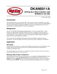
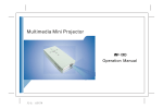
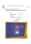
1
VGA Graphics Controller using SRAM
Memory
TSTE12, version 0.3
This lab will introduce the use of IP units as well as hierarchical schematic entry.
This section discusses the design of a graphics controller driving a computer monitor. Included is a
description of the timing for the signals that drive a monitor and a description of an VHDL module
that will let you drive a monitor with a picture stored in the SRAM memory.
The top level description of the design is shown below in Figure 1. The system consists of the
computer monitor connected to the FPGA board. The FPGA board contains the SRAM with the
image inside, the FPGA, and a 50 MHz clock source. Inside the FPGA will a PLL structure create a
65 MHz clock used by all the logic (VGA Controller and Memory Interface). Two green LED will
also indicate clock rate and reset state.
VGA_top
Div65M
50 MHz
reset_n
65 MHz
reset_n
PLL
Graphic_gen
VGA
Controller
Memory
Interface
Conmputer
Monitor
SRAM
FPGA
Figure 1: Overview of the complete system
1 VGA Graphics Controller (VGA_top)
The XGA resolution computer monitor is connected to the FPGA board through a 15 pin miniDSUB VGA connector. This connector contains three analog color information signal, ground
signals, and two synchronization signal HSYNC and VSYNC. The image to be shown is stored in
the SRAM memory.
1.1
Requirements
Here are the requirements to pass the laboratory
●
Implement the design using hdl_designer.
●
The two leftmost 7-segment displays shall indicate your lab group number.
●
The rightmost right green LED should blink with a rate of 1 s and. The second to right
should indicate current lock signal of the PLL. The blink rate should be controlled by the
internal 65 MHz clock (not the 50MHz clock).
●
Declare a symbol and corresponding VHDL view.
1
1.2
●
Create the model in hdldesigner with one block for each process. Call the top level
VGA_top. Use at least three hierarchy levels including the top level symbol VGA_top.
For example, divide the unit into a sync generation part and a color generation part.
●
It is not allowed to have more than one clock domain (disregarding the PLL). The best
way to check this is to not have more than one signal appearing on statements using
’event or the rising_edge() function call.
●
Synthesize the design and demonstrate the function on the DE2-115 FPGA board.
VGA Color Signals
There are three signals -- red, green, and blue -- that send color information to a VGA monitor. In
an CRT monitor drives each of these three signals an electron gun that emits electrons, which paint
one primary color at a point on the monitor screen. Analog levels between 0 (completely dark) and
0.7 V (maximum brightness) on these control lines tell the monitor what intensities of these three
primary colors to combine to make the color of a dot (or pixel) on the monitor's screen.
Each individual analog color input can be set to one of 28 (=256) levels by controlling the corresponding digital 8-bit input vector (either vga_r, vga_g, or vga_b to the digital-to-analog converters
in the VGA DAC chip. The 256 possible levels on each analog input are combined by the monitor
to create a pixel with one of 256x256x256 = 16 M different colors.
1.3
VGA Signal Timing
The monitor image is painted by controlling the focal point of the electron gun focus point (the
color) using deflection circuits. The focal point is moved line by line on the monitor, starting from
the top left corner and ending at the bottom right corner. The number of lines and the number of
pixels on each line defines the resolution of the image, in this lab it will be 1024x768 pixels (XGA
resolution). The deflection circuits require two synchronization signals in order to start and stop the
deflection circuits at the right times so that a line of pixels is painted across the monitor and the
lines stack up from the top to the bottom to form an image. The waveforms sent to the VGA is
shown in Figure 2, with the expected frequency and times given in the DE2-115 user manual (see
also Table 1, XGA(60Hz) is used in this lab).
av bv
cv
dv
ah bh
ch
dh
RGB
Vsync
RGB
Hsync
Figure 2: VGA waveforms
2
Table 1: Detailed timing for various screen resolutions
Negative pulses on the horizontal sync signal mark the start and end of a line and ensure that the
monitor displays the pixels between the left and right edges of the visible screen area. The actual
pixels are sent to the monitor within a 15.75 us (1024/65e6) window. The horizontal sync signal
drops low a minimum of 0.37 us (24/65e6) after the last pixel and stays low for 2.1 us (136/65e6).
A new line of pixels can begin a minimum of 2.46 us (160/65e6) after the horizontal sync pulse
ends. So a single line occupies 15.75 us of a 20.68 us interval. The other 4.93 us of each line is the
horizontal blanking interval during which the screen is dark.
In an analogous fashion, negative pulses on a vertical sync signal mark the start and end of a frame
made up of video lines and ensure that the monitor displays the lines between the top and bottom
edges of the visible monitor screen. The lines are sent to the monitor within a 15.88 ms window.
The vertical sync signal drops low a minimum of 62 us (3 lines) after the last line and stays low for
0.124 ms (6 lines). The first line of the next frame can begin a minimum of 0.60 ms (29 lines) after
the vertical sync pulse ends. So a single frame occupies 15.88 ms of a 16.67 ms interval. The other
0.79 ms of the frame interval is the vertical blanking interval during which the screen is dark.
1.4
VGA Signal Generator Algorithm
We now have to figure out a process that will send pixels to the monitor with the correct timing and
framing. We can store a picture in the SRAM of the DE2-115 Board. Then we can retrieve the data
from the SRAM, format it into lines of pixels, and send the lines to the monitor with the appropriate
pulses on the horizontal and vertical sync pulses.
3
An example of pseudocode for a single frame of this process is shown in Figure 3. The pseudocode
has two outer loops: one which displays the L lines of visible pixels, and another which inserts the
V blank lines and the vertical sync pulse. Within the first loop, there are two more loops: one which
sends the P pixels of each video line to the monitor, and another which inserts the H blank pixels
and the horizontal sync pulse.
for line_cnt=1 to L
/* send L lines of video to the monitor */
for pixel_cnt=1 to P
/* send P pixels for each line */
data = RAM(address)
/* get pixel data from the memory */
address = address + 1
/* FLASH data word contains 4 pixels */
color = COLOR_MAP(data)
/* get the color for the right-bit pixel */
send color to monitor
pixel_cnt = pixel_cnt + 1
for horiz_blank_cnt=1 to H
/* blank the monitor for H pixels */
color = BLANK
send color to monitor
/* pulse the horizontal sync at the right time */
if horiz_blank_cnt>HB0 and horiz_blank_cnt<HB1
hsync = 0
else
hsync = 1
horiz_blank_cnt = horiz_blank_cnt + 1
line_cnt = line_cnt + 1
for vert_blank_cnt=1 to V
/* blank the monitor for V lines and insert vertical sync */
color = BLANK
send color to monitor
/* pulse the vertical sync at the right time */
if vert_blank_cnt>VB0 and vert_blank_cnt<VB1
vsync = 0
else
vsync = 1
vert_blank_cnt = vert_blank_cnt + 1
/* go back to start of picture in memory */
address = 0
Figure 3: VGA signal generation pseudocode
Within the pixel display loop, there are statements to get the next word from the SRAM. Each word
contains one pixel. Since it has only 16 bits, each pixel can store one of 65536 levels of color or
gray. The mapping from the 16 bit pixel value to the actual values required by the monitor
electronics is done by the COLOR_MAP() routine. In this design we only make use of 65536
colours, with 6 bits red (bits 15 downto 10) and 5 bits each for green (bits 9 downto 5) and blue (4
downto 0).
Reading memory will take one clock cycle (applying the address at one rising clock edge, and
reading data at the next rising clock edge). Applying the color mapping and sending the pixel to the
pins may take additional time. It is therefore important to understand the timing of the design,
especially related to the blanking signals. It may therefore be necessary to add additional delaty to
the blanking signals. Failing this may cause the image to lack color on the edges of the image or
have duplicated pixels on the image edges.
1.5
Problem definition
Here are the definitions listed that are needed to complete the design.
1.5.1
Port definitions
The inputs and outputs of the circuit as defined are as follows:
4
Name
fpga_clk
Type
Range
Description
IN
std_logic
The system clock
fpga_reset_n IN
std_logic
The circuit reset signal. Reset is active low, i.e.,
fpga_reset_n='0' gives reset
vga_clk
OUT std_logic
The DAC clock signal. Typically pixel clock signal.
vga_sync
OUT std_logic
Not in use. Inactivate this with a logical '0'
vga_blank_n OUT std_logic
The blank signal from the design.
vga_r
OUT std_logic_vector
7 downto 0
The red component of the display rgb signal. Always set
the unused lower 2 bits to '0'
vga_g
OUT std_logic_vector
7 downto 0
The green component of the display rgb signal. Always
set the unused lower 3 bits to '0'
vga_b
OUT std_logic_vector
7 downto 0
The blue component of the display rgb signal. Always set
the unused lower 3 bits to '0'
vga_hsync_n OUT std_logic
The display horizontal sync pulse, active low
vga_vsync_n OUT std_logic
The display vertical sync pulse, active low
sram_data
The display data from SRAM
IN
std_logic_vector
15 downto 0
sram_address OUT std_logic_vector
19 downto 0
The address to display data SRAM. Always set unused
bits to '0'
sram_we_n
OUT std_logic
SRAM write enable. Set to '1' while reading image
sram_oe_n
OUT std_logic
SRAM output enable. Set to '0' while reading image
sram_ce_n
OUT std_logic
SRAM chip select. Set to '0' while reading image
sram_lb_n
OUT std_logic
SRAM lower byte strobe. Set to '0' while reading image
sram_ub_n
OUT std_logic
SRAM upper byte strobe. Set to '0' while reading image
HEX7
OUT std_logic_vector
6 downto 0
Most Significant Digit of your lab group number. See
lab1 for more information
HEX6
OUT std_logic_vector
6 downto 0
Least Significant Digit of your lab group number. See
lab1 for more information.
GLED
OUT std_logic_vector
1 downto 0
Two green LED, one indicating PLL lock state, the other
flashing with 1 second cycle time
Pin location for these signals can be found in the board documentation available at
/sw/altera/kits/DE2/DE2_user_manual/DE2_UserManual.pdf,
/sw/altera/kits/DE2_70_SYSTEM_cd_v1.2/DE2_70_SYSTEN_cd_v1.2/DE2_70_user_manual/DE
2_70_User_manual_v107.pdf, or
/sw/altera/kits/DE2_115_v1.0.5_SystemCD/DE2_115_user_manual/DE2_115_User_manual.pdf.
5
1.5.2
Interface
The synthesis tool needs to know how the FPGA is connected to the external world. An attribute
description included in the the VHDL description will be used for this purpose. How to include this
into the design was described in the keyboard exercise.
With guidance from the port definitions each group has to create its own attribute description. All
necessary information is found in the documentation of the "DE2-115 education board - users
manual".
1.5.3
Top-level Structure of the VGA Signal Generator
The pseudocode and pipeline timing in the last section will help us to understand the structure and
create the VHDL code for a VGA signal generator.
1.5.3.1
Inputs and outputs
fpga_clk
The input for the 50 MHz clock of the DE2-115 board. It should only be used as input to the PLL
that will use this clock as a reference and create a new 65 MHz clock that will be used in the rest of
the design.
fpga_reset_n
Reset the PLL. Will stop the clock generation when fpga_reset_n = '0'. Connect this to one of the
push buttons on the board.
vga_clk
The vga_clk is used by the DAC to clock the individual pixels. Create this by inverting the internal
65 MHz clock. The pixel and sync signals should then be stable when the positive edge of vga_clk
reaches the DAC chip.
vga_hsync_n, vga_vsync_n
The outputs for the horizontal and vertical sync pulses.
vga_blank_n
The output for the display blank signal. A '0' on this signal forces the DAC-chip to blank its outputs.
vga_r, vga_g, vga_b
The outputs that is used by the DAC chip to create the red, green, and blue analog color gun signals.
Each pixel in the memory encodes the pixel color as three parts, <r5...r0 g4...g0 b4...g0>, the 6
leftmost bits (MSB bits) should be used as MSB bits for vga_r, etc. The remaining unused lower
bits in the vga_r, vga_g and vg_b output should be set to '0'.
SRAM_address, SRAM_data
The outputs for driving the address lines of the SRAM memory and the inputs for receiving the data
from the SRAM.
6
SRAM_oe_n, SRAM_we_n, SRAM_ce_n,SRAM_lb_n, SRAM_ub_n
Control signals for the SRAM interface. Forces the SRAM to be read all the time, using 16 bit data
interface. More information is available in the DE2-115 users manual and SRAM datasheet.
1.5.3.2
Signals
Signal can be added directly into the block diagram. The name and type of these signals are
automatically set to be equal to the name and type of the port that they are connected to. Names can
be changed by double-clicking on the name in the block diagram or on the wire itself.
fpga_clock_65M
Internal FPGA clock generated by the PLL component. This should be the only clock signal used
by the rest of the design (excluding the 50 MHz clock used as input to the PLL component). It is
connected to the c0 output of the PLL.
reset_n
Internal reset signal. This is a copy of the locked signal from the PLL. The rest of the design should
be reset when reset_n is '0'. This should also be shown on one of the green LEDs.
1.5.3.3
Components
These three components should be placed in the top level, that is, the structural description of the
VGA_top component. The two components Div65M and Graphic_gen is added by simply selecting
the blue component block symbol, while the PLL must first be created separately, and then added to
the structure.
Div65M
Divides the 65MHz clock frequency by 65 000 000, thereby producing a alternating output signal
blinking with a 1 second cycle. Build this as a counter that counts from 65 000 000/2 downto 0, and
when reaching zero inverts the output bit and restarts counting.
Graphic_gen
The part of the design that generates monitor control signals, generates an SRAM memory address,
and output pixel color based on the data from the SRAM memory. Details is described later.
PLL
This is an example of an IP block. This component creates a 65 MHz clock signal used in the rest of
the design. It is based on a hardware block in the FPGA consisting of both analog and digital
circuitry such as voltage controlled oscillators, dividers, filters etc. It is possible to create and
synchronize multiple clocks using one input clock as a reference.
The IP block will not be synthesized is the usual way creating a netlist of lookup tables and flip
flops. The IP will instead consist of a simulation model useful for verifying the function using
simulation, and a post-synthesis configuration information used to configure the PLL in the FPGA.
Creation of the simulation model and configuration information for the PLL is done using a special
software package called Altera MegaWizard. It is started from HDL designer by first pressing on
Tasks/templates on the right edge of the Design manager window. Double click on the Altera
MegaWizard icon as shown in Figure 4.
7
Figure 4: Altera Megawizard available in the middle of the right column
The dialog window shown in Figure 5 appears. Make sure that the library definition is the library of
lab2. If not, select “Specify library” and select the correct library. Press OK.
Read the warning that follows, and remember to not change the directory path, only add the
component name, in the window that is opened next.
The MegaWizard applications first window presented. Select to create a new custom megafunction
variation and select Next.
Figure 5: Altera Megawizard start window
8
Figure 6: Selecting name and type of IP block
The 2nd window of the MegaWizard is shown. Carefully add the name PLL to the end of the output
filename path (should still point to /tmp/...). The device family should be set to Cyclone IV E and
VHDL output file be selected. Open the I/O folder in the left subwindow and select the function
ALTPLL as seen in Figure 6. Press Next.
Figure 7: Defining input frequency of the PLL
9
The first of the windows used to specify parameters for the PLL is shown in Figure 6. Specify the
input clock frequency (50 MHz). Press Next.
Make sure there will be areset and locked signals on the component are shown in the next window
and adjust the settings if necessary. Then select the window tab named “3 Output clocks” at the top
of the window.
Select to specify output frequency and enter 65 MHz as shown in Figure 8. Press Finish.
Figure 8: Selecting output clock frequency
Press Finish again to generate the component. The new component should now be visible in the
design manager window.
Adding the generated PLL into the block diagram of VGA_top is done by first selecting the green
component symbol at the top of the VGA_top struct block diagram window, then drag and drop the
PLL component from the component browser window into the block diagram. Select yes if asked
about adding an additional library definition of altera_mf.
1.5.4
Graphics_gen component
The Graphic_gen component contains the logic that controls the memory and the computer monitor.
It should consist of the two blocks Memory_interface and VGA_controller. The Memory interface
shall produce the SRAM address and control signals, while VGA_controller generates monitor
control signals and translates the incoming sram_data into red, green and blue color data. The
following description shows one way to implement this functionality.
10
1.5.4.1
Signals
hcnt, vcnt
The counters that store the current horizontal position within a line of pixels and the vertical
position of the line on the screen. We will call these the horizontal or pixel counter, and the vertical
or line counter, respectively. The line period is 20.68 µs that is 1344 vga_clk cycles, so the pixel
counter needs at least eleven bits of resolution. Each frame is composed of 806 video lines (only
768 are visible, the other 38 are blanked), so a ten bit counter is needed for the line counter.
pixrg
The 16-bit register that stores the pixel received from the SRAM.
hblank, vblank, pblank
The video blanking signal and its registered counterpart that is used in the next pipeline stage.
1.5.4.2
Processes
pixelcounter
This process describes the operation of the horizontal pixel counter. The counter is synchronously
set to zero when the fpga_reset_n is applied. The counter increments on the rising edge of each
fpga_clock_65M cycle. The range for the horizontal pixel counter is [0,1343]. When the counter
reaches 1343, it rolls over to zero on the next cycle. Thus, the counter has a period of 1344 pixel
clocks. With a pixel clock of 65 MHz, this translates to a period of 20.68 µs.
linecounter
This process describes the operation of the vertical line counter. The counter is synchronously set to
zero when the reset input is low. The counter increments when the rising edge of the horizontal sync
pulse is detected, that is, after a line of pixels is completed. The range for the vertical line counter is
[0,805]. When the counter reaches 805, it rolls over to zero on the next cycle. Thus, the counter has
a period of 806 lines. Refer to the the tables in the end of 1.3, “ VGA Signal Timing” for more
information on the length of each subpart.
hsyncr
This process describes the operation of the horizontal sync pulse generator. The horizontal sync is
set to its inactive high level when the reset is activated. During normal operations, the horizontal
sync output is updated on every pixel clock. Refer to the the tables in the end of 1.3, “ VGA Signal
Timing” for more information on the length of each subpart.
Here is also the hblank signal created. The video is blanked after the 1024 pixels of a line are
displayed. The blanking signal is active high.
vsyncr
This process describes the operation of the vertical sync pulse generator. The vertical sync is set to
its inactive high level when the reset is activated. During normal operations, the vertical sync output
is updated after every line of pixels is completed. Refer to the the tables in the end of 1.3, “ VGA
Signal Timing” for more information on the length of each subpart.
Here is also the vblank signal created. The video is blanked after 768 lines are displayed. The
blanking signal is active high.
11
blank_syncr
This process describes the operation of the pipelined video blanking signal. Within the process, the
blanking signal is stored in a register so it can be used during the next stage of the pipeline when the
color is computed.
Computation of the combinatorial blanking signal. The total blank is calculated as vga_blank_n =
not (hblank OR vblank).
SRAM_control
The SRAM is permanently selected and writing to the SRAM is disabled. It stores the video data.
The image we will display is stored in a linear sequence of words inside the SRAM. The address to
the SRAM is a linear counter updated every clock cycle whenever the hblank is not active. The
counter can be reset to 0 whenever the vertical blanking is started.
pixel_reg
This process describes the operation of the register that holds the word (16 bits) of pixel data read
from SRAM. The register is asynchronously cleared when the VGA circuit is reset. The register is
updated on the rising edge of each fpga_clock_65M.
vga_gen
This process describes the process by which the current active pixel is mapped into the 24 bits that
drive the red, green and blue color guns. The register is set to zero (which displays as the color
black) when the reset input is low. The color register is clocked on the rising edge of the
fpga_clock_65M clock since this is the rate at which new pixel values arrive. The value clocked
into the register is a function of the pixel value and the blanking input.
When the pipelined blanking input is low (inactive), the color displayed on the monitor is a color
value depending the input value from SRAM. This means we send different parts of the SRAM
value to all the RGB inputs to achieve a color image. When the pipelined blanking input is high, the
color register is loaded with zero (black).
1.6
Tips and tricks
To aviod a lot of trouble in the design phase a few hints are useful
●
Do not use multiple clock definitions, i.e. , use only one signal (fpga_clock_65M) with
’EVENT or rising_edge() to define a clock. The use of ’EVENT and ’LAST_VALUE are
not useful in the context of synthesis except for defining the rising or falling edge of the
clock fpga_clock_65M.
●
Introductionto Megafunctions
http://www.altera.com/literature/ug/ug_intro_to_megafunctions.pdf
This document will explain how to create an function with mega-wizard
●
Let the top level design only contain the PLL, the LED driver, and one block containing
the total VGA controller. This allows the VGA simulation to be run without having to
simulate the PLL (the PLL is time consuming to simulate)
●
Use a simple model of the SRAM contents to figure out if the timing is correct. The
simulation model of the SRAM should have a signal update delay of approximately 4 ns,
and give different data outputs for each address, e.g., copy the 16 least significant bits of
12
the address to the data. Use this in a testbench (that you create) and look at the red, green
and blue signals together with the blank and sync signals.
1.7
Synthesis flow (using Precision)
Follow the steps lined up in the keyboard laboratory exercise.
1.8
Downloading the Design
Follow the steps described in the keyboard laboratory exercise.
2 Document history
120620
Add PLL, change resolution to 1024x768 with 1 pixel/word, switch to DE2-115 board using
SRAM.
100909 V0.2
Updated pin names to avoid clash with reset_n and clarify active level by adding _n
Fix pseudo code to indicate 4 pixels / word
Clarify the polarity of vga_blank_n
100902 V0.01
First version addressing the DE2-70 using FLASH
13