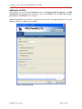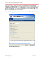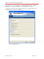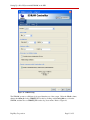
1
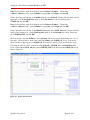
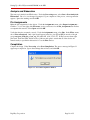
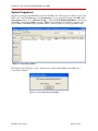
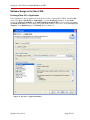
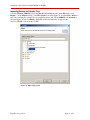
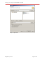
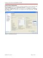
DKAN0011A Setting Up a Nios II System with SDRAM on the DE2 04 November 2009 Introduction This tutorial details how to set up and instantiate a Nios II system on Terasic Technologies, Inc.’s DE2 Altera Development and Education Board. The system includes an interface to the board’s 8MB SDRAM chip and runs the application program from SDRAM. It also sets up and implements the LCD, sevensegment displays, red and green LEDs, switches, and pushbuttons. Background Nios II is a 32-bit RISC CPU designed for implementation as a soft core in Altera FPGAs. Altera’s System-on-a-Programmable-Chip (SOPC) Builder allows users to design Nios II systems easily by selecting Nios II processors, setting up the associated memory, and adding any desired standard and/or custom peripherals. Once generated, the system is incorporated into an FPGA design with Altera’s Quartus II software and instantiated on the FPGA. Altera provides the Nios II Integrated Development Environment (IDE) for application software development. This tutorial includes instructions for running an example C application from SDRAM. Application DE2 Setup This tutorial assumes that the user is familiar with the DE2 board and already has the USB-Blaster device installed. Refer to the Getting Started with Altera’s DE2 Board tutorial for more information on installing the USB-Blaster driver. Also, these programs are case sensitive. If a component is named or renamed, it needs to match what is written in this tutorial exactly, or it may not work. Starting a New Project in Quartus II Open the Quartus II software and create a new project by selecting File > New Project Wizard. Create a new folder on the C:\ drive called Tutorial_Files and create another folder inside of that one called SDRAM. Specify the SDRAM folder as the working directory for this project. Also, in the second box, call the project name SDRAM. The top level entity on the third line automatically fills in. See Figure 1. Page 1 of 35 Setting Up a Nios II System with SDRAM on the DE2 Figure 1. New Project Wizard Make sure the new folders were created directly on the C:\ drive and that there are no spaces in the folder names. This ensures that there are no spaces in the directory path. Folders created in the My Documents folder cause errors. For instance, C:\Documents and Settings\Firstname_Lastname\My Documents causes an error because of the spaces in the directory path. Digi-Key Corporation Page 2 of 35 Setting Up a Nios II System with SDRAM on the DE2 Click the Next button, and click Next again on page 2. On the third page, select the EP2C35F672C6 chip as the target device, as shown in Figure 2. This is the FPGA on the DE2 board. Click Next on the remaining two screens, and click Finish. Figure 2. FPGA Selection Create a new block diagram by selecting File > New, selecting Block Diagram/Schematic File, and clicking OK. To save this file, select File > Save As (not to be confused with Save Project), call it SDRAM, and click Save. Naming it SDRAM ensures that this block diagram file is the top most entity of the project, as specified in Figure 1. Digi-Key Corporation Page 3 of 35 Setting Up a Nios II System with SDRAM on the DE2 Nios II System Design in SOPC Builder The next step is to build a Nios II processor system. Select Tools > SOPC Builder. In the pop-up window, set the System Name to NiosII_Processor and the Target HDL to either Verilog or VHDL. Select OK. It is not necessary to know VHDL or Verilog to continue, so select either one. Refer to Figure 3. Figure 3. Create New Nios II System Error and warning messages appear and disappear sporadically in the information box on the bottom of the screen while performing the following steps. Ignore these errors; they disappear upon successful completion of the Nios II system. Clock Settings In the Clock Settings pane, double click clk_0, and rename it CLOCK_50. Press Enter. The SDRAM requires another clock to be added to the system, so click the Add button to the right of the Clock Settings pane. Once a new clock appears, double-click on it and rename it CLOCK_100. To the right of this new clock, under MHz, double-click on the 50, and change it to 100. Refer to Figure 4. Figure 4. External System Clocks Add On Chip Memory On the upper left side of the SOPC Builder window, under Component Library, expand the Memories and Memory Controllers column, then expand On-Chip, and select On-Chip Memory (RAM or ROM). Click the Add button and the MegaWizard appears. Set Block Type to M4K, set Total Memory Size to 20, and select Kbytes. Do not change any other default settings. Click Finish. Refer to Figure 5. Errors may occur after adding the On-chip memory. Ignore these errors, because they disappear as more components are added to the system. Digi-Key Corporation Page 4 of 35 Setting Up a Nios II System with SDRAM on the DE2 Figure 5. On-Chip Memory Setup Digi-Key Corporation Page 5 of 35 Setting Up a Nios II System with SDRAM on the DE2 Add a Nios II Processor Now, add the Nios II processor to the system. In the upper left corner of the SOPC window, under Component Library, select Nios II Processor, and click the Add button. In the middle of the MegaWizard window, select Nios II/s as a Nios II core. Set Hardware Multiply to None. Do not change any other of the default values. Click Finish and the Nios II processor is added to the system. See Figure 6. Figure 6. Nios II Processor Setup Digi-Key Corporation Page 6 of 35 Setting Up a Nios II System with SDRAM on the DE2 Add a JTAG UART In order to communicate to the Nios II processor through the USB-Blaster, add the JTAG UART to the system. In the upper left corner of the SOPC window, under Component Library, expand Interface Protocols, expand Serial, select JTAG UART, and click Add. Do not change any of the default settings. Click Finish. Refer to Figure 7. Figure 7. JTAG UART Setup Digi-Key Corporation Page 7 of 35 Setting Up a Nios II System with SDRAM on the DE2 Add an LCD To add the LCD, expand Peripherals, then expand Display, select Character LCD, and click Add. There are no settings to modify, so select Finish. Refer to Figure 8. Rename the lcd_0 that was generated to ensure proper functionality. Select lcd_0, right-click on it, select Rename, rename it to lcd, and press Enter. Figure 8. LCD Controller Setup Digi-Key Corporation Page 8 of 35 Setting Up a Nios II System with SDRAM on the DE2 Add Parallel I/O (PIO) Add switches to the system. Expand Peripherals, then expand Microcontroller Peripherals, select PIO (Parallel I/O), and click Add. When the window opens, set the Width to 18, set the Direction to input ports only, and click Finish. Refer to Figure 9. Rename the pio_0 that was generated to ensure proper functionality. Select pio_0, right-click on it, select Rename, rename it to switch, and press Enter. Figure 9. PIO Switch Setup Digi-Key Corporation Page 9 of 35 Setting Up a Nios II System with SDRAM on the DE2 Add the pushbuttons next. Similar to the switches, expand Peripherals, expand Microcontroller Peripherals, select PIO (Parallel I/O), and click Add. When the window opens, set the Width to 4 and set the Direction to input ports only. Go to the Input Options tab, check the synchronously capture box, and select Falling edge. Also, underneath in the Interrupt section, check Generate IRQ, select Edge, and then click Finish. Refer to Figures 10 and 11. Rename the pio_0 that was generated to ensure proper functionality. Select pio_0, right-click on it, select Rename, rename it to pb, and press Enter. Figure 10. PIO Pushbutton Setup Digi-Key Corporation Page 10 of 35 Setting Up a Nios II System with SDRAM on the DE2 Figure 11. PIO Pushbutton Interrupt Setup Digi-Key Corporation Page 11 of 35 Setting Up a Nios II System with SDRAM on the DE2 The green LEDs are added next. Expand Peripherals, expand Microcontroller Peripherals, select PIO (Parallel I/O), and click Add. Do not change any of the default settings. The interface is set up for an 8bit output-only PIO, which is needed to use the green LEDs. Click Finish. Refer to Figure 12. To ensure proper functionality, rename the pio_0 that was generated. Select pio_0, right-click on it, select Rename, rename it to ledg, and press Enter. Figure 12. PIO Green LED Setup Digi-Key Corporation Page 12 of 35 Setting Up a Nios II System with SDRAM on the DE2 Add the red LEDs next. Expand Peripherals, expand Microcontroller Peripherals, select PIO (Parallel I/O), and click Add. Set the Width to 18 and click Finish. Refer to Figure 13. To ensure proper functionality, rename the pio_0 that was generated. Select pio_0, right-click on it, select Rename, rename it to ledr, and press Enter. Figure 13. PIO Red LED Setup Digi-Key Corporation Page 13 of 35 Setting Up a Nios II System with SDRAM on the DE2 Add the seven-segment displays to the system. Expand Peripherals, expand Microcontroller Peripherals, select PIO (Parallel I/O), and click Add. Set the Width to 16 and click Finish. Repeat the previous step three more times to set up all eight of the seven-segment displays. Refer to Figure 14. To ensure proper functionality, rename the pio_0-3 that were generated. Select pio_0-3, right-click on them, select Rename, and rename them to seven_seg_01, seven_seg_23, seven_seg_45, and seven_seg_67. Figure 14. PIO Seven-Segment Display Setup Add SDRAM To add the SDRAM, expand Memories and Memory Controllers, expand SDRAM, select SDRAM Controller, and click Add. Set Presets: to Custom, change the Bits to 16, and click Finish. Do not change any of the other values. Refer to Figure 15. Digi-Key Corporation Page 14 of 35 Setting Up a Nios II System with SDRAM on the DE2 Figure 15. SDRAM Setup The SDRAM operates at a different clock speed than the rest of the system. Under the Clock column, change the sdram_0 clock to CLOCK_50. Do this by clicking on the Clock_100 across from the SDRAM, and then choose CLOCK_50 from the drop down menu. Refer to Figure 16. Digi-Key Corporation Page 15 of 35 Setting Up a Nios II System with SDRAM on the DE2 Figure 16. SDRAM CLOCK_50 To run the application from SDRAM instead of On-chip memory, specify it in the cpu_0 MegaWizard. Select cpu_0 in the Module Name list, right-click on it, and select edit. Set the Reset Vector and the Expansion Vector to sdram_0 as shown in Figure 17. Select Finish. Figure 17. SDRAM Configuration Digi-Key Corporation Page 16 of 35 Setting Up a Nios II System with SDRAM on the DE2 Assign Base Addresses To avoid conflicts between system components, set their base addresses. To auto assign the base addresses, select System > Auto-Assign Base Addresses. Refer to Figure 18. Figure 18. Auto-Assign Base Addresses Change the interrupt request (IRQ) priorities for the JTAG UART. Click the IRQ value for the jtag_uart_0 component to select it. Type 16, and press Enter to assign it a new IRQ value. Refer to Figure 19. Figure 19. JTAG UART IRQ Setup Generate System Finally, generate the system. Click the Generate button on the bottom of the screen. If prompted to save the changes, do so. When the system generation is complete, a message entitled Info: System generation was successful appears in the message box. Upon successful system generation, close the SOPC Builder window. Digi-Key Corporation Page 17 of 35 Setting Up a Nios II System with SDRAM on the DE2 Block Diagram Design in Quartus II Add Processor Now that the SOPC system is built, implement it in the block diagram file. Open the Quartus II window. Right-click on the blank block diagram within the SDRAM.bdf tab. Click Insert > Symbol. A Symbol window opens. In the Libraries pane, expand Project, select NiosII_Processor, and click OK. Refer to Figure 20. Figure 20. Insert Nios II Processor Add VCC Click to place the symbol somewhere in the block diagram window. Right-click on the block diagram window again, and click Insert > Symbol. Expand the c:/altera/…/libraries folder, expand primitives, expand other, select vcc, check the box labeled Repeat-insert mode, and click OK. Place vcc somewhere on the left side of the NiosII_Processor block near reset_n. Place another vcc somewhere on the bottom right side of the block. The initial placements of vcc are not important, as they can be moved later. Hit the Esc key on the keyboard after both instances of vcc are placed. Digi-Key Corporation Page 18 of 35 Setting Up a Nios II System with SDRAM on the DE2 Add Output Pins Right-click somewhere in the blank space again, and click Insert > Symbol. Expand the c:/altera/…/libraries folder, expand primitives, expand pin, and select output. Check the box called Repeat-insert mode and click OK. Place two output pins just below the NiosII_Processor block. After both output pins are placed, hit Esc on the keyboard. Move the mouse to the blue line coming from reset_n on the block diagram. The mouse cursor should change into a cross-hair shape. When this happens, click and hold in order to draw a line connecting reset_n to the closest vcc. Let go of the mouse as soon as a small box shape appears on vcc. Click and hold vcc in order to move it. When vcc is moved, the line that was just drawn follows vcc. If the line moves with vcc, there is a proper connection. If not, click and drag the mouse to connect the line between reset_n and vcc. Connect both of the output pins to the other vcc following these same steps. Double-click one of the output pins to open the Pin Properties window. In the Pin name(s): section, rename the pin to LCD_ON, and click OK. Rename the other pin LCD_BLON. Refer to Figure 21. Figure 21. Rename Output Pins Add a PLL Right-click somewhere in the block diagram again, and click Insert > Symbol. Click on the MegaWizard Plug-In Manager… button. In the new window, select Create a new custom megafunction variation, and click Next. Refer to Figure 22. Digi-Key Corporation Page 19 of 35 Setting Up a Nios II System with SDRAM on the DE2 Figure 22. MegaWizard Plug-In Manager, Page 1 On the left side, under Installed Plug-Ins, expand I/O and click on ALTPLL. On the right side, where it asks for the name, browse to where the project is stored, and name it pll_block. If it was created on the C:\ drive as described in this tutorial, the path name should be C:\Tutorial_Files\Test2\SDRAM\pll_block. Click Next. Refer to Figure 23. Figure 23. MegaWizard Plug-In Manager, Page 2 Digi-Key Corporation Page 20 of 35 Setting Up a Nios II System with SDRAM on the DE2 On the ALTPLL page, leave the speed grade set to 6. Change the frequency of the inclock0 input to 50 MHz. Click Next. Refer to Figure 24. Figure 24. MegaWizard Plug-In Manager, Page 3 Digi-Key Corporation Page 21 of 35 Setting Up a Nios II System with SDRAM on the DE2 On page 4, deselect Create an ‘areset’ input to asynchronously reset the PLL, and also deselect Create ‘locked’ output. Click Next. Refer to Figure 25. Figure 25. MegaWizard Plug-In Manager, Page 4 Digi-Key Corporation Page 22 of 35 Setting Up a Nios II System with SDRAM on the DE2 Click Next on page 5. On page 6, select Enter output clock parameters: and verify that 100 MHz is in the Requested settings. Click Next. Refer to Figure 26. Figure 26. MegaWizard Plug-In Manager, Page 6 Digi-Key Corporation Page 23 of 35 Setting Up a Nios II System with SDRAM on the DE2 On page 7, check Use this clock. On the Clock phase shift option, change the Requested settings to -3.00ns. The deg might need to be changed to ns before selecting -3.00. Verify that the value is negative. Click Next. Refer to Figure 27. Figure 27. MegaWizard Plug-In Manager, Page 7 Digi-Key Corporation Page 24 of 35 Setting Up a Nios II System with SDRAM on the DE2 Click Next on pages 8 and 9, and click Finish on page 10. The Symbol window opens again. Click OK, and place the newly created pll_block to the left of the NiosII_Processor block. Refer to Figure 28. Figure 28. PLL Block Placement Digi-Key Corporation Page 25 of 35 Setting Up a Nios II System with SDRAM on the DE2 Right-click somewhere in the block diagram, and click Insert > Symbol…. Expand the c:/altera/…/libraries folder, expand primitives, expand pin, select input, and click OK. Click to place this pin to the left of the inclk0 terminal on the pll_block. Double-click the newly created input pin to open the Pin Properties window. In the Pin name(s): section, rename the pin to CLOCK_50, and click OK. Right-click somewhere in the block diagram, and click Insert > Symbol…. Expand the c:/altera/…/libraries folder, expand primitives, expand pin, select output and click OK. Click to place this pin to the left of the CLOCK_50 terminal on the NiosII_Processor. Double-click the newly created output pin to open the Pin Properties window. In the Pin name(s): section, rename the pin to SDRAM_CLK, and click OK. Move the mouse to the blue inclk0 line on the pll_block. The mouse cursor should change into a crosshair shape. Click and hold to draw a line connecting inclk0 to the CLOCK_50. Let go of the mouse when a small box shape appears on CLOCK_50. If a small “X” appears, it is not connected properly. Following the same procedure, connect c1 on the pll_block to CLOCK_50 on the NiosII Processor block, connect c0 and Clock_100, and connect SDRAM_CLK to the line between CLOCK_50 and c1. Refer to Figure 29. Figure 29. pll_block Connections Digi-Key Corporation Page 26 of 35 Setting Up a Nios II System with SDRAM on the DE2 Pin Generation Right-click on the NiosII_Processor block, and click Generate Pins for Symbol Ports. Input and output pins are automatically generated for the rest of the Nios II system. Verify that the newly generated pins do not cover the vcc placed earlier. Move vcc to a different location if it is covered. Refer to Figure 30 for the completed block diagram. Figure 30. Complete Quartus II System Digi-Key Corporation Page 27 of 35 Setting Up a Nios II System with SDRAM on the DE2 Analysis and Elaboration The next step is Analysis and Elaboration. Under the Processing menu, select Start > Start Analysis & Elaboration. Choose to save changes if prompted. Upon completion of the process, a message window appears. Ignore the warnings and click OK. Pin Assignments Make the pin assignments for the devices. Under the Assignments menu, select Import Assignments… Click the … box to the right of the File name: section, and browse for the Pin_Assignments.csv file that accompanies this tutorial. Select Open and click OK. Verify that the pins are named correctly. Under the Assignments menu, select Pins. In the Filter: menu, choose Pins: unassigned. Only 8 pins should appear in the list: pins [7] and [15] from each of the pin groups out_port_from_the_seven_seg_XX (where XX is 01, 23, 45, 67). If there are more than eight pins listed, check the SOPC builder section of this tutorial again to ensure that all of the devices are named exactly as specified in this tutorial. Close the Pins window. Compilation Compile the design. Under Processing, select Start Compilation. The success message in Figure 31 appear upon completion. Ignore the warnings that are listed, and click OK. Figure 31. Successful Compilation Window Digi-Key Corporation Page 28 of 35 Setting Up a Nios II System with SDRAM on the DE2 System Programmer Plug the power supply and USB-Blaster cable into the DE2 board. Hit the red power button to turn on the DE2 board. Under the Tools menu, select Programmer. If a pop-up window appears, click OK. In the Programmer window, choose Hardware Setup… Verify that the USB-Blaster[USB-0] is selected, and click Close. Verify that the Mode: selected is JTAG. Set switch SW19 on the DE2 board (next to the LCD) to Run. Click Start in the programmer window. Refer to Figure 32 for the programmer setup. Figure 32. Programmer Window The window shown in Figure 33 opens. This window confirms that the FPGA on the DE2 board successfully configured. Figure 33. Successful Connection Window Digi-Key Corporation Page 29 of 35 Setting Up a Nios II System with SDRAM on the DE2 Software Design in the Nios II IDE Creating a New C/C++ Application Next, implement a software application for the Nios II system. Open the Nios II IDE. Under the File menu, select New > Nios II C/C++ Application to open the New Project window. In the Name: section, type Tutorial_SDRAM. In the SOPC Builder System PTF File, browse to the location where the NiosII_Processor was saved (when created with SOPC builder), and open it. Under Select Project Template, select Blank Project. Click Finish. Refer to Figure 34. Figure 34. New C/C++ Application Window Digi-Key Corporation Page 30 of 35 Setting Up a Nios II System with SDRAM on the DE2 Importing Source and Header Files Select the Tutorial_SDRAM folder in the Nios II C/C++ Projects pane. In the File menu, select Import… In the Import window, select File System as shown in Figure 35, and click Next. Browse to the folder containing the example files accompanying this tutorial. Check SDRAM.c and header.h as shown in Figure 36, and click Finish. SDRAM.c and header.h should now appear in the Tutorial_SDRAM folder in the Nios II IDE. Figure 35. Import File System Digi-Key Corporation Page 31 of 35 Setting Up a Nios II System with SDRAM on the DE2 Figure 36. Import Files Digi-Key Corporation Page 32 of 35 Setting Up a Nios II System with SDRAM on the DE2 System Library Configuration Before the program can be run, it is necessary to adjust the system library properties. Right-click on the Tutorial_SDRAM folder, and select System Library Properties. A new window opens. Select sdram_0 in the Program memory (.text): drop-down menu. Also select sdram_0 for the Read-only data memory (.rodata): drop-down menu. Do not change any of the other default settings. Click OK. Refer to Figure 37. Figure 37. System Library Properties Digi-Key Corporation Page 33 of 35 Setting Up a Nios II System with SDRAM on the DE2 Running the Software Finally, run the program. Right-click on the Tutorial_SDRAM folder, and select Run As > Nios II Hardware. If prompted to save changes, click Yes. It may take some time for the program to build, but, upon successful completion, a message similar to the following displays in the Console tab: nios2-terminal: connected to hardware target using JTAG UART on cable nios2-terminal: "USB-Blaster [USB-0]", device 1, instance 0 nios2-terminal: (Use the IDE stop button or Ctrl-C to terminate) The DE2 board should be running the program. If the sample code was used, the LCD should display: You Are AWESOME! LCD Works ### The seven-segment displays count in hexadecimal, and the green LEDs count in binary. If a switch is switched to the up position, the red LED above the switch turns on. If the pushbutton KEY0 is pressed, all of the devices count down instead of up. If KEY1 is pressed, the devices resume counting up. Each time KEY2 is pressed, the devices count incrementally faster. Likewise, each time KEY3 is pressed, the devices count incrementally slower. If any changes are made to the code, right-click on Tutorial_SDRAM, and select Run As > Nios II Hardware to run the new code. Conclusion This application note explains how to set up a Nios II system that uses the SDRAM on Terasic Technologies, Inc.’s DE2 board. The LCD controller, pushbuttons, seven-segment displays, switches, and red and green LEDs on the DE2 board are also used. Additional Information Getting Started with Altera’s DE2 Board. Altera Corporation. 2008. DE2 User Manual. Altera Corporation. 2005. Nios II Processor Reference Handbook. Altera Corporation. 2009. Nios II Software Developer’s Handbook. Altera Corporation. 2009. Quartus II Handbook, Volume 5: Embedded Peripherals. Altera Corporation. 2009. Digi-Key Corporation Page 34 of 35 Setting Up a Nios II System with SDRAM on the DE2 Disclaimer This document is for informational use only and is subject to change without prior notice. Digi-Key makes no commitment to update or keep current the information contained herein. Digi-Key does not guarantee or warrant that any information provided is accurate, complete, or correct and disclaims any and all liability associated with the use of the information contained herein. The use of this information and Digi-Key’s liability is subject to Digi-Key’s standard Terms & Conditions which can be found at www.digi-key.com by clicking on the Terms & Conditions link at the bottom of the web page. No license, whether express, implied, arising by estoppel or otherwise is granted under any intellectual property or other rights of Digi-Key or others. Trademarks DIGI-KEY is a registered trademark of Digi-Key Corporation. All other trademarks, service marks and product names contained herein are the sole property of their respective owner and their use is for informational purposes only and does not imply any endorsement, recommendation, sponsorship or approval by the trademark owner of the contents. Copyright Use of this document is limited to customer’s internal business use for the evaluation and purchase of products. No permission is granted to the user to copy, print, store, distribute, transmit, display in public or modify the content of this document in any way for any other purpose. Copyright 2009 Digi-Key Corporation. All rights reserved. Digi-Key Corporation Page 35 of 35