1
Dynamic Series Actuator & Controller
Operating Manual
Intelligent Actuator, Inc.
This publication was written to assist you in better understanding this part of your IA system. If you require further assistance, please
contact IA Technical Support. For Central and East Coast Time Zones, please call our Itasca, IL office at 1-800-944-0333 or FAX630467-9912. For Mountain and Pacific Time Zones, please call our Torrance, CA office at 1-800-736-1712 or FAX 310-891-0815; Monday thru
Friday from 8:30AM to 5:00PM.
Intelligent Actuator, Inc.
U.S. Headquarters
2690 W. 237th Street
Torrance, CA 90505
310-891-6015 / 310-891-0815 FAX
Intelligent Actuator, Inc.
Midwest Regional Office
1261 Hamilton Parkway
Itasca, IL 60143
630-467-9900/ 630-467-9912 FAX
www.intelligentactuator.com
© January 1998 Intelligent Actuator, Inc. All rights reserved.
No portion of this publication may be reproduced, stored in a retrieval system, or transmitted, in any form or by any means, electronic,
mechnical, recording, or otherwise, without the prior written permission of Intelligent Actuator, Inc.
Disclaimer
The information and technical data contained herein are subject to change without notice. Intelligent Actuator, Inc. assumes no responsibility for
any errors or omissions regarding the accuracy of the information contained in this publication.
Table of Contents
DS
Part I DS Controller ........................................................................................................................ 3~25
Foreword ............................................................................................................................................................................ 3
1.
Safety Precautions and Warranty ..................................................................................................................................... 4
2.
Setting Up .......................................................................................................................................................................... 5
3.
Part Names and Functions ............................................................................................................................................ 6~9
3.1 Part Names ................................................................................................................................................................. 6
3.2 Functions ................................................................................................................................................................... 7
3.3 Explanation of Code Display ...................................................................................................................................... 9
4.
Specifications ............................................................................................................................................................ 10~16
4.1 Controller Specifications ...........................................................................................................................................10
4.2 External I/O Specifications .........................................................................................................................................11
4.3 Interface List ..............................................................................................................................................................13
4.4 TEACHING/RS232PORT ...........................................................................................................................................15
4.5 PORT .........................................................................................................................................................................16
5.
Dimensions ..................................................................................................................................................................... 17
5.1 Plastic Type ...............................................................................................................................................................17
6.
Installation Environment and Noise Measures ......................................................................................................... 18~21
6.1 Installation Environment ...........................................................................................................................................18
6.2 Power Source .............................................................................................................................................................18
6.3 Noise Suppression ....................................................................................................................................................18
6.4 Heat Dissipation and Mounting .................................................................................................................................21
6.5 Power Supply to the Controller .................................................................................................................................21
7.
Connections .............................................................................................................................................................. 22~25
7.1 Connection Method ..................................................................................................................................................22
7.2 Diagram of External Device Connector ......................................................................................................................25
8.
Moving the Actuator .................................................................................................................................................. 26~34
8.1 Program Mode ...........................................................................................................................................................27
8.2 Operation Using the Positioning Mode .....................................................................................................................30
9.
Error Code List ............................................................................................................................................................... 35
10. Maintenance. ................................................................................................................................................................... 36
Part II DS Actuator Slider Type .................................................................................................... 37~40
1.
General ............................................................................................................................................................................ 37
1.1 Part Names .................................................................................................................................................................37
1.2 Operating Environment .............................................................................................................................................37
2.
Installation ................................................................................................................................................................ 38~40
2.1 Installing the Actuator ..............................................................................................................................................38
2.2 Attaching the Work Piece ..........................................................................................................................................39
2.3 Wiring Cable ..............................................................................................................................................................40
2.4 Adjusting the Home Position ....................................................................................................................................40
2.5 Load On the Actuator ................................................................................................................................................40
Page 1
DS
Table of Contents
3.
Maintenance .............................................................................................................................................................. 41~45
3.1 Maintenance Schedule .............................................................................................................................................. 41
3.2 Cleaning the Exterior ..................................................................................................................................................41
3.3 Inspecting the Interior ...............................................................................................................................................42
3.4 Lubrication ................................................................................................................................................................ 43
3.5 Checking the Dust Shield ...........................................................................................................................................45
Part III
DS Actuator Arm Type ................................................................................................. 46~55
1.
General .......................................................................................................................................................................... 46
1.1 Part Names .................................................................................................................................................................46
1.2 Operating Environment ............................................................................................................................................. 46
2.
Installation ................................................................................................................................................................ 47~49
2.1 Installing the Actuator .............................................................................................................................................. 47
2.2 Attaching the Work Piece ..........................................................................................................................................48
2.3 Wiring Cable ..............................................................................................................................................................49
2.4 Adjusting the Home Position ....................................................................................................................................49
2.5 Changing the Motor Position ....................................................................................................................................49
3.
Maintenance .............................................................................................................................................................. 50~55
3.1 Maintenance Schedule .............................................................................................................................................. 50
3.2 Cleaning the Exterior ..................................................................................................................................................50
3.3 Inspecting the Interior ...............................................................................................................................................50
3.4 Lubrication ................................................................................................................................................................ 51
3.5 Inspecting and Replacing the Timing Belt .................................................................................................................52
3.6 Inspecting and Adjusting the Brake ..........................................................................................................................54
Part IV
DS Actuator Specifications .......................................................................................... 56~65
1.
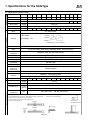
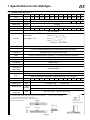
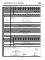
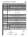
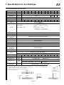
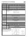
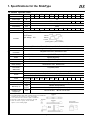
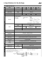
Specifications for the Slider Type ............................................................................................................................. 56~64
1.1 High speed type
DS-SA6H .................................................................................................................56
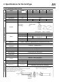
1.2 Medium speed type
DS-SA6M ................................................................................................................ 57
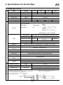
1.3 Low speed high thrust type
DS-SA6L .................................................................................................................58
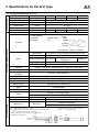
1.4. High speed type
DS-SA5H .................................................................................................................59
1.5 Medium speed type
DS-SA5M ................................................................................................................ 60
1.6 Low speed high thrust type
DS-SA5L .................................................................................................................61
1.7 High speed type
DS-SA4H .................................................................................................................62
1.8 Medium speed type
DS-SA4M ................................................................................................................ 63
1.9 Low speed high thrust type
DS-SA4L .................................................................................................................64
2.
Specifications for theArm Type
2.1 Medium speed type
2.2 Low speed high thrust type
2.3 Medium speed type
2.4 Low speed high thrust type
*
Appendix ................................................................................................................................... 69~70
1. Trouble Shooting ....................................................................................................................................................... 69
......................................................................................................................... 65~68
DS-A6M ..................................................................................................................65
DS-A6L ...................................................................................................................66
DS-A5M ..................................................................................................................67
DS-A5L ...................................................................................................................68
Page 2
Foreword
DS
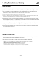
Thank you very much for selecting the Intelligent Actuator, DS series actuator/controller system. The DS series is
compact, easy to use and can control the actuator and peripheral devices with ease. Also, the SEL language used in
the DS series makes it possible to perform high level control with simple programming. Please read through this
manual carefully to gain an understanding of the proper method of operating and handling the DS controller and
actuator.
Page 3
1. Safety Precauitions and Warranty
DS
Safety Precautions:
This product was developed as components for driving automated equipment and is designed not to produce greater torquing or
speed than is necessary. However, strictly observe the following items to prevent any accidents from occurring.
1. As a rule, any handling or operating methods not described in this manual should be viewed as things that should not be
attempted. Please contact the company if any portion of the contents of this manual are unclear.
2. Use only the products specified for wiring between the actuator and controller.
3. Stand clear of the operating range of the machine when it is in motion or is ready to operate. Surround the system with safety
partitions if there is a possibility that people can enter the area where the machine is being used.
4. When assembling, adjusting, or performing maintenance on the machine, always disengage the power supply to the controller.
During work, display a sign stating work in progress where it is readily visible. Also, keep the power cable close to the operator
so that another person cannot inadvertently switch on the power.
5. When more than one person is working on the system, agree on signals beforehand to ensure everyone's safety before
beginning work. In particular, when doing work involving axis movement, always call out for everyone's safety regardless of
whether power is ON or OFF, or the axis is to be mechanically driven or manually moved.
6. When the user needs to lengthen the cables, check the wiring carefully to make sure it is correct before turning the power ON
since miswiring can lead to misoperation.
Warranty Period and Scope:
1. This product is under warranty for a period of one year from the date it is shipped to the customer. If the product breaks down
due to a manufacturing defect during this period, IAI will repair it at no cost.
2. The following are not covered under the warranty, even if the product is still under the warranty period.
a. Damage due to incorrect handling or use that does not adhere to the instructions in the user's manual.
b. When electrical or mechanical revisions have been performed on the product.
c. Part wear when traveling distance has exceeded 5,000 km.
d. Breakdown or damage caused by fire, earthquake or other natural disasters.
e. Any other breakdown or damage that is not recognized as the company's responsibility.
Page 4
2. Setting Up
DS
1. Precautions When Using the Emergency Stop
As a rule, emergency stops should only be applied from the I/O.
Do not turn the power (AC117V) ON/OFF to effect an emergency stop.
If you stop the actuator by turning the power OFF, wait at least 15 seconds before turning the power ON again. If you disregard
this warning, and repeatedly turn the power ON/OFF without waiting a sufficient amount of time, you may damage the controller.
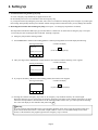
2. Restarting the Controller After an Emergency Stop (refer to part 3, 1-4 "Emergency Stop Release" for details)
The Super SEL controller and Table Top type (TT-300) both use a "hard reset" to restart after an emergency stop. The operation is nearly the same as turning the power OFF/ON. (Homing is required).
(1) Emergency Stop from the teaching pendant
Press EMERGENCY STOP on the teaching pendant. Continue pressing and the screen will display the following.
Controller code display
Teaching pendant display
EMG STOP.
EG
(A red *ALARM lamp lights up)
ReStart (Flashing display)
F1
F2
F3
F4
Take your finger off the EMERGENCY STOP button to do a hard reset and the following screen appears.
Controller code display
Teaching pendant display
EMG STOP.
rd
(A green *READY lamp lights up)
ReStart (Flashing display)
F1
F2
F3
F4
If you press the F1 key (ReStart) on the teaching pendant, the initial screen reappears.
Controller code display
Teaching pendant display
IA. Super. SEL
Teach V1.00 07/18/94
Start (Flashing display)
F1
F2
F3
rd
(A green *READY lamp lights up)
F4
(2) Pressing the controller emergency stop button or an emergency stop condition caused by an external signal
When the emergency stop is released after pressing the emergency stop button on the controller front panel, you must
follow the same procedure as described above or the teaching pendant will not reset (you cannot operate the teaching
box if the code display on the controller front panel reads EG .
! Warning
If you are using the Auto Start PRG in the system program parameter mode, always write the program so that movement will not resume unless there is some kind of input condition. This is to avoid sudden startup of movement
because of the automatic start program right after the emergency stop is released.
Page 5
DS
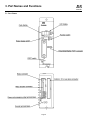
3. Part Names and Functions
Controller
3.1 Part Names
Page 6
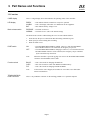
3. Part Names and Functions
DS
Controller
3.2 Functions
CODE display
This is a 3-digit display device that indicates the operating status of the controller.
LED display
READY
ALARM
BAT.
Brake release switch
RELEASE : The brake is released.
NORMAL : The brake is ON. (This is the normal setting)
: This indicates that the controller is ready to be operated.
: This is the display when there is a malfunction in the equipment.
: This indicates battery voltage is low.
The brake release switch is enabled durng the servo free state indicated below:
1.
2.
3.
PORT switch
From the time the power is turned ON until the homing command is given.
When [Svof] is selected during direct teaching.
When an alarm occurs.
ON
OFF
Function switch
TEACHING/RS232
PORT connector
: The TEACHING/RS232PORT is enabled. However, when the TEACHING/
RS232 PORT connector is not connected, an emergency stop occurs.
: The TEACHING/RS232PORT is disengaged. However, even when the TEACHING/RS232PORT connector is not connected, the emergency stop is controlled
by the external E-stop connection.
Note:
When the controller is powered up, plug in or remove the TEACHING/RS232PORT
connector when the PORT switch is OFF.
BAU.R
COPY
F/R
: This is the switch for changing the Baud rate.
: This is the switch for COPY from ROM to FLASH memory.
: This is the switch for changing FLASH and ROM.
Note:
At the time the unit is shipped, all switches are set to OFF so use them under
normal circumstances.
This is a 25 pin RS232 connector for the teaching pendant or to a personal computer.
Page 7
DS
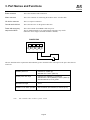
3. Part Names and Functions
Controller
Brake connector
This is the actuator's brake connection.
Motor connector
This is the connector for connecting the actuator motor • encoder cable.
I/O device connector
This is a 34 pin I/O connector.
Ground terminal block
This is the M3 screw for the ground connection.
Power and emergency
stop terminal block
This is the terminal for POWER N and 24V power.
The two EMG terminals are for connecting the emergency stop switch.
(When the unit is shipped, the EMG terminal is shorted.)
POWER EMG
24V
)
N
The user should meet the requirements and conditions given in the table below with respect to the power lines that are
connected.
Suitable power line
Usable power line range
Solid wire φ1.2 (AWG 16)
Standard wire 1.25mm2 (AWG 16)
Solid wire φ0.4 (AWG26)~ φ1.2 (AWG 16)
Standard wire 0.3mm2 (AWG22)~1.25mm2 (AWG 16)
Standard diameter φ0.18 or greater
Standard line length
11mm
Suitable tool for button operation
Slot screwdriver (axis diameter φ3, width of tip 2.6)
Note:
This controller does not have a power switch.
Page 8
DS
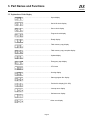
3. Part Names and Functions
Controller
3.3 Explanation of Code Display
...................................................................... Open display
............................................................... Serial I/O check display
............................................................... Servo check display
............................................................... Program check display
............................................................... Ready display
............................................................... Flash memory copy display
............................................................... Flash memory copy complete display
............................................................... Update display
............................................................... Emergency stop display
............................................................... CPU reset
............................................................... Homing display
............................................................... Startup program No. display
............................................................... Position No. display (001~500)
............................................................... Interrupt error display
............................................................... Software error display
............................................................... Other error display
Page 9
DS
4. Specifications
Controller
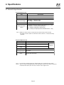
4.1 Controller Specifications
Item
Description
Power Voltage
D C 24V ± 10%
Power Current
24W Rated/1A (Maximum 48W)
Ambient Temperature & Humidity
Temperature: 0~40°C Humidity 85% RH or less
Operating Environment
Free of corrosive gas, no excessive dust
Isolation Resistance
500V 10MΩ or more
Unit Weight
560g
Safety Features
(Motor excess current: Excess voltage • Driver temperature check)
Overload Check, software limit check
Motor
AC Servo Motor 20W
Control Functions
Multi-task Control Super SEL Controller
Memory Capacity
Total: 1000 steps, 500 positions
Memory Device
COMS RAM Battery Backup
Number of programs
32 programs, Multi-task function (maximum of 8 programs)
Input/Output (DC24V)
Non-insulated
Driver alarm
Dedicated inputs: 8 (PRG No. 1, 2, 4, 8 ,1, 20)
Dedicated inputs: 1 (START)
User inputs: 15
Dedicated outputs: 2 (Ready, ALARM)
User outputs: 6
Data Input Method
Teaching Pendant or RS232 Communication
Communication
EIA RS232 Standard Asychronous
Remote Update Functions
Software update (via network or floppy disk)
Page 10
DS
4. Specifications
Controller
4.2 External I/O Specifications
External Input Circuit
Item
Specification
External Power Voltage
Input Current
D C 24V ± 10%
7mA / DC24V
ON voltage • • • Main DC 18 OV
OFF voltage • • • Main DC 6 OV
ON / OFF Voltage
Insulation
Non-insulated
No-voltage contact point (minimum load about DC 5V • 1mA)
Photoelectric • proximity sensor (NPN type)
PLC Transistor output (open collector type)
PLC Contact point output (minimum load about DC5V • 1mA)
Extent Connection
Device
Note: When a no-contact circuit is connected to an external circuit, make sure that
the leakage current is under 1mA when the switch if OFF or, it could cause faulty
operation.
External Output Circuit
Item
Load Voltage
Specification
D C 24V
maximum Load Voltage 100mA / 1 point 400mA peak (all current)
Recommend Load
Voltage
Leakage Current
Application for
TD62084
20mA / 1 point
Max 0.1mA
InsulationExternal
Connection Device
Non-insulated
External Connection
Device
Miniature relay
Sequence input unit (sink type)
Note 1: For all of the external outputs, the flyback diode (D) is connected on the inside.
Note 2: Take care when connecting because if the load short circuits or the current exceeds the
maximum load current, this will cause a failure in the output circuit.
Page 11
DS
4. Specifications
Controller
External I/O Circuit
Circuit protective element
L
R
ZZ
R
Ω
3.3KΩ
CCP2E50 (Fuse)
220µ H
1A
1B
IN
24V
(1)
100KΩ
⇐
2A
2B
3A
3B
4A
4B
5A
5B
6A
6B
7A
7B
8A
8B
9A
10A
10B
11A
11B
12A
12B
Internal
circuit
R
10Ω
⇐
Internal
circuit
Circuit protective element
L
Page 12
CCP250
13A
13B
IN (24)
OUT (1)
14A
14B
15A
15B
16A
16B
17A
OUT (8)
17B
N
4. Specifications
DS
Controller
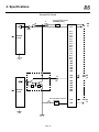
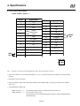
4.3 Interface List
Specifications for I/O Interface during program mode and position mode are different.
The interface list for each is indicated in the following tables::
Position Mode
I/O Connector (34 Pin)
Pin N o.
Section
1A
P 24
Port N o.
Function
C able C olor
External currenrt + 24v i n out
1-Brown
1B
NC
1-Red
2A
NC
1-Orange
2B
NC
1-Yellow
3A
NC
1-Green
3B
NC
1-Blue
4A
NC
1-Purple
4B
Reserve
1-Gray
5A
C PU Reset Input
1-Whi te
000
Start Input
1-Black
6A
001
Hold Input
2-Brown
6B
002
NC
2-Red
003
NC
2-Orange
004
Posi ti on No. 1 Input
2-Yellow
005
Posi ti on No. 2 Input
2-Green
5B
7A
7B
Input
8A
8B
006
Posi ti on No. 4 Input
2-Blue
9A
007
Posi ti on No. 8 Input
2-Purple
9B
008
Posi ti on No. 10 Input
2-Gray
10A
009
Posi ti on No. 20 Input
2-Whi te
10B
010
Posi ti on No. 40 Input
2-Black
11A
011
Posi ti on No. 80 Input
3-Brown
11B
012
Posi ti on No. 100 Input
3-Red
12A
013
Posi ti on No. 200 Input
3-Orange
12B
014
Posi ti on No. 400 Input
3-Yellow
13A
015
NC
3-Green
13B
300
Alarm Output
3-Blue
14A
301
Ready Output
3-Purple
14B
302
Posi ti oni ng C omplete Output
3-Gray
303
NC
3-Whi te
304
NC
4-Black
15A
15B
Ouput
16A
305
NC
4-Brown
16B
306
NC
4-Red
17A
307
NC
4-Orange
Emergency C urrent OV
4-Yellow
17B
N24
Caution:
External 24V power must be
connected to I/O connector
1A pin and 17B. Make sure
that the power is OFF during
connection, and avoid short
circuit and reverse connection.
Note:
PRG = Program
NC = No contact
Do not use number 1B (PRG No.1 input) through pin number 4A (PRG No.20) since these are for program number input.
Position mode can be used when program number input is "0" (OFF).
When using the controller in position mode, use pin number 7B (Port No.004) through pin number 12B(Port No. 014) for
position number input.
* Homing is performed when position number input is "0" (OFF) and start input is set to "1" (ON).
* Please note that when the I/O connector (external 24V power) is not connected, the controller considers all input ports and
program inputs to be "1" (ON). In this case, the controller changes to reset status.
*
*
*
Page 13
DS
4. Specifications
Controller
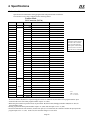
Program Mode
I/O Connector (34 pin)
Pin N o.
Section
1A
P 24
Port N o.
External currenrt + 24v i n out
1-Brown
PRG No. 1 Input
1-Red
2A
PRG No. 2 Input
1-Orange
2B
PRG No. 4 Input
1-Yellow
3A
PRG No. 8 Input
1-Green
3B
PRG No. 10 Input
1-Blue
4A
PRG No. 20 Input
1-Purple
4B
Reserve
1-Gray
C PU Reset Input
1-Whi te
5B
000
Start Input
1-Black
6A
001
User Input
2-Brown
6B
002
User Input
2-Red
7A
003
User Input
2-Orange
7B
Input
004
User Input
2-Yellow
8A
005
User Input
2-Green
8B
006
User Input
2-Blue
9A
007
User Input
2-Purple
9B
008
User Input
2-Gray
10A
009
User Input
2-Whi te
10B
010
User Input
2-Black
11A
011
User Input
3-Brown
11B
012
User Input
3-Red
12A
013
User Input
3-Orange
12B
014
User Input
3-Yellow
13A
015
User Input
3-Green
13B
300
Alarm Output
3-Blue
14A
301
Ready Output
3-Purple
14B
302
User Output
3-Gray
15A
303
User Output
3-Whi te
15B
Ouput
304
User Output
4-Black
16A
305
User Output
4-Brown
16B
306
User Output
4-Red
User Output
4-Orange
Emergency C urrent OV
4-Yellow
17A
17B
307
N24
Note:
*
C able C olor
1B
5A
*
Function
Caution:
External 24V power must be
connected to I/O connector
1A pin and 17B. Make sure
that the power is OFF during
connection, and avoid short
circuit and reverse connection.
PRG = Program
Please use pin No. 1B (PRG No.1 input) through pin No. 4A (PRG No.20) for inputting program numbers.
Please note that when the I/O connector (external 24V power) is not connected, the controller considers all input ports and
program inputs to be "1" (ON). In this case, the controller changes to reset status.
Page 14
DS
4. Specifications
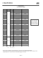
Controller
4.4 TEACHING/RS232PORT
D-Sub 25 DTE ( Special X )
EMG
SW
)
Pin No.
Signal Name
1
FG
2
TXD
3
RXD
4
5
(RTS)
Short Circuit
(CTS)
6
D SR
7
SG (GND)
8
NC
9
NC
10
NC
11
NC
12
EMG S2
13
EMG S1
Pin No.
Signal Name
14
NC
15
NC
16
NC
17
NC
18
+ 6V Output
19
ENABLE
20
DTR
21
NC
22
NC
23
EMG-STOP
24
NC
25
GND
*
*
*
*
ENABLE
SW
*
*
PORT SW
Note: Controller will E-stop if Teaching/RS232 port SW is ON with nothing connected.
* In the case of RS232C, never connect pin numbers 12, 13, 18, 19, 23 and 25 since these are signal wires for the teaching
pendant.
* Pin numbers 4 and 5 are shorted.
* Since pin numbers 18 and 19 are connecting terminals for the ENABLE SW, it is necessary to connect these when the
servo is ON.
* TEACHING/RS232 PORT SW
PORT SW (ON) • • • •
PORT SW (OFF) • • • •
The teaching pendant or RS232 communication lines can be used.
The connector function stops.
The pin numbers 12 and 13 EMG SW and the pin numbers 18 and 19 ENABLE SW are
shorted internally.
Page 15
DS
4. Specifications
Controller
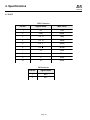
4.5 PORT
MPG Connector
Pin No.
Signal Name
Wire Color
1
5V
Red
2
GND
Black
3
PG A
Gray
4
PG B
Yellow
5
PG Z
Green
6
PG Z
Brown
7
FG
Clear
8
U
Red
9
V
White
10
W
Black
BK Connector
Pin No.
Signal Name
1
BK+
2
BK-
Page 16
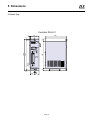
5. Dimensions
DS
Controller
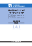
5.1 Plastic Type
Controller DS-S-C1
4
46
109
23
10
4
23
O5
CONTROLLER
CODE
READY
ALARM
BAT
139
151
R2.5
TEAING/
RS232 PORT
ON
OFF
PORT
10
IAI Corporation
4
159
BRAKE
RELEASE
NORMAL
23
5
23
Page 17
6. Installation Environment and Noise Measures
DS
Controller
6.1 Installation Environment
(1) Do NOT block the air vents of your controller during installation and wiring.
(Not only will insufficient ventillation prevent optimal performance, but it may lead to a malfunction in the controller)
(2) Your DS Controller is NOT dust, water, or oil proof. Take steps to prevent foreign matter from getting into the controller
air vents. Avoid using your controller in environments subject to contamination by dust, oil mist, or cutting oil.
(3) Do not expose your controller to direct sunlight or place it near a heat source.
(4) The controller should be used in an environment where the ambient temperature is 0oC ~4 0oC, humidity 85% or less
(no condensation) and is free of corrosive or inflammable gases.
(5) Avoid external vibration, unnecessary impact, or excessive shocks to your controller.
(6) Take steps to shield all cables and wires from electromagnetic noise.
6.2 Power Source
Power supply is DC24V.
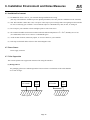
6.3 Noise Supression
This section explains noise suppression measures when using the controller.
(1) Wiring & Power
For grounding, please use a dedicated ground of Class D or better. The thickness of the cable should be
2.0~5.5mm2 or larger.
DS Controller
Other
Devices
Class 3 ground
Correct
DS Controller
Other
Devices
Avoid this method
Page 18
6. Installation Environment and Noise Measures
DS
Controller
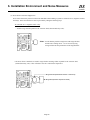
(2) Noise Source and Noise Suppression
Noise comes from many sources but the most immediate when building a system are solenoid valves, magnetic switches
and relays. Noise from the devices can be prevented by taking the following steps:
AC solenoid valve · magnetic switch · relay
• Install a surge absorber parallel to the reactance load (solenoid and relay coils).
*Note* Use the shortest possible wiring between the surge absorber
and the noise-creating device. Use of excessively long
wiring will decrease the performance of the surge absorber.
• The most effective method is to install a surge absorber and surge killer in parallel to the reactance load
(solenoid and relay coils). This will reduce noise in a wide band of frequencies.
Surge Absorber (Metal Oxide Varistor or Transzorb)
Surge Killer (Resistor Capacitor Snubber)
Page 19
6. Installation Environment and Noise Measures
DS
Controller
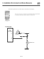
Install a diode in parallel with a coil • Diode Capacity is determined by the load capacity.
In the case of DC power, be careful not to exceed the diode polarity as this can lead
to a breakdown of the diode, inside the controller or of the DC power.
Circuit Example
DS
Controller
VO3C
+24V
OUT
CR
AC 100V
MY2
DC24V
CR
COM
0V
SOL
0V
Solenoid Valve
Page 20
ENB221D-14A
6. Installation Environment and Noise Measures
DS
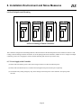
6.4 Heat Dissipation and Mounting
Air Flow According to Natural Convention
This controller is designed for assembling inside the control board. Since the heat dissipation for this controller is about 10~12W,
cooling is done according to natural convention. As for the spacing between the controllers, whether or not it's a single or multiple
controllers, please leave enough space so that controller mounting and removal may be done easily.
6..5 Power Supply to the Controller
(1) Please make sure that the power is OFF when wiring into to the I/O connector and main power.
(2) Please make sure that the N(OV) is common when setting the main power and I/O power separately.
(3) To maintain safety during emergency stop, when cutting off the main power of the controller, close/open just the
24V side.
Page 21
DS
7. Connections
Controller
7.1 Connection Method
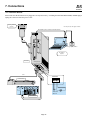
Please make sure that all connectors are plugged in correctly and securely. Excluding the TEACING/RS232 PORT, do NOT plug or
unplug the connectors while the power is ON!
Teaching Pendant
(Option)
DS TEACHING BOX
F1
F2
F3
* You may not use other types of cables.
F4
RS232 Cable* (5m) is included in the PC Software
CONTROLL
CODE
READY
ALARM
BAT.
2m
BRAKE
RELEA
NORMA
Emergency Stop SW Box
TE
RS2
PC Software
(Option)
ON
OFF
PORT
Controller
IAI Corporation
BK
o
PG
M
1
PO
WE
R
24
G
EM
N
V
5m
POWER EMG
Servo Actuator
N 24V
POWER
MITUBISHI
INPUT
MITUBISHI
OUTPUT
24V Power
Over 2A
External Device
2m
Page 22
EMG
SW
DS
7. Connections
Controller
(1) Connect the motor · encoder cable and brake cables coming from the actuator to the connector.
(2) Connect the teaching pendant to the controller. After connecting, turn the PORT Switch ON.
(If it is OFF, the teaching pendant will not work when the power is turned ON)
(3) Supply 24V power to the controller terminal block (power).
a) Power Terminal Block, as shown on Page 6.
b) External I/O device connector, between Pin No. 1A (24V, cable color brown) and Pin No. 17B.
(OV cable color yellow).
(4) If the CODE display shows,
If the CODE display shows,
in sequence, then, the DS Controller is ready to operate.
then, the EMERGENCY STOP input will release.
a) Power 24V DC must be supplied to the external I/O.
b) Input pin No. 5A for the external I/O should be logically OFF.
If the CODE display is,
then, either a CPU reset has been input or I/O current is disconnected.
The controller preparation is now complete.
Note 1: The controller terminal block (EMG) is for connecting an emergency stop switch and is a b-type contact input
(normally closed). When the unit is shipped, it is shorted and the emergency stop is released.
Note 2: Do not recycle power quickly.
Page 23
7. Connections
DS
Controller
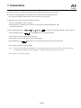
7.2 Diagram of External Device Connector
The following is an example of connections with an external device in the program mode.
Signal N ame
1
N
2
24V
3
24V
4
EMG SW
EMG SW
)
Pin N o.
I/O Connector (34 pin)
S ection
1A
P 24
P ort N o.
Function
•
E xternal current + 24V i n out
1B
P RG No. 1
Input
2A
P RG No. 2
Input
2B
P RG No. 4 Input
3A
P RG
3B
P RG No. 10 Input
Digital SW
P in N o.
• •
No. 8 Input
•
4A
P RG No. 20 Input
4B
Reserve
5A
C P U S et Input
•
•
5B
000
Start Input
6A
001
User Input
•
6B
002
User Input
•
003
User Input
•
7B
004
User Input
•
8A
005
User Input
•
8B
006
User Input
•
9A
007
User Input
•
9B
008
User Input
10A
009
User Input
•
10B
010
User Input
•
11A
011
User Input
•
11B
012
User Input
•
12A
013
User Input
•
12B
014
User Input
13A
015
User Input
13B
300
A larm Output
14A
301
Ready Output
14B
302
User Output
15A
303
User Output
15B
304
User Output
16A
305
User Output
16B
306
User Output
17A
307
User Output
7A
Input
•
•
•
•
•
•
•
•
•
Output
17B
N24
E xternal C urrent OV
•
•
•
•
•
•
•
•
•
•
•
•
•
•
•
OV
Page 24
24V
7. Connections
DS
Controller
Pin N o.
Signal N ame
1
N
2
24V
3
24V
4
EMG SW
)
The following is an example of connections with an external device in the position mode.
• •
I/O Connector (34 pin)
P in N o.
S ection
1A
P 24
P ort N o.
Function
•
E xternal current + 24V i n out
1B
NC
2A
NC
2B
NC
3A
NC
3B
NC
4A
NC
4B
NC
5A
C P U Reset
•
5B
000
Start Input
•
6A
001
Hold Input
•
6B
002
NC
003
NC
7A
Input
7B
004
P osi ti on No. 1
Input
•
8A
005
8B
006
P osi ti on No. 2
Input
•
P osi ti on No. 4
Input
•
Input
9A
007
P osi ti on No. 8
9B
008
P osi ti on No. 10
10A
009
10B
010
•
Input
•
P osi ti on No. 20
Input
•
P osi ti on No. 40
Input
•
11A
011
P osi ti on No. 80
Input
•
11B
012
P osi ti on No. 100 Input
•
12A
013
P osi ti on No. 200 Input
•
12B
014
P osi ti on No. 400 Input
•
13A
015
NC
13B
300
A larm Output
14A
301
Ready Output
14B
302
P osi ti on C ompleti on A larm
15A
303
NC
304
NC
•
•
•
•
•
Output
15B
16A
305
NC
16B
306
NC
17A
17B
307
N24
NC
E xternal C urrent OV
•
OV
Page 25
24V
DS
8. Moving the Actuator
Controller
There are two ways to move the actuator. One is the program mode where a program in the memory drives the actuator, and the
other is the positioning mode where the actuator is moved between recorded positions.
8.1 Program Mode
There are two methods of operating the actuator in the program mode. The first is "operation from a teaching pendant" and
"operation using the PC software" which are used for simple operating checks (during program debugging on a trial run).
The second is "automatic operation based on parameter settings" and "operation based on selection of external signals" which
are used in general application examples on site. The following section explains the second method.
Automatic operation using the
parameter setting
Parameter setting is done either by using the teaching pendant
or PC software.
↓
Set Automatic Start Program No.
Enter the number of the program to be automatically
started in the system parameter item, "Auto Start Program No."
located on the controller side.
↓
Reset the Controller
Reset the controller by releasing the emergency stop after it
occurs, or by turning the power OFF, then ON again.
↓
Automatic Program Start
After resetting the controller, the program number that was
entered, automatically starts.
Precautions when using an auto start program:
The servo actuator will start automatically, immediately after the controller is reset which may startle the operator.
To ensure safety, always use an interlock at the start of a program, such as having the actuator operate after receiving a
confirmation signal. To start simultaneous multiple-programming, set all other programs into EXPG command, placing
them ahead of the main auto program. As always, please take safety precautions when using an auto start program.
Page 26
DS
8. Moving the Actuator
Controller
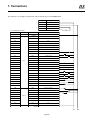
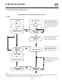
Operation Based on the External Start Signal Selection
(1) Program Operation
Controller
External Device
Power ON
Power ON
↓
↓←
READY output
READY signal ON
Connect the controller to the
external devices using the program
mode.
⇒
READY signal
confirmed?
N
When the READY signal turns ON,
the READY lamp (green) on the
controller front panel lights up.
Y
↓
I/O Processing
→
↓
⇐
Program No.
confirmed?
N
→
→
↓
External start input
⇐
Y
↓ ←
Program operation
N→
N
Controller
abnormal?
Y
→
Emergency stop
⇐
When the program is executed, the
number of that program shows up
N in the code display on the controller
front panel.
Y
↓
Emergency stop input
Emergency stop
signal confirmed?
Start signal from the external device
is input.
Start signal ON
↓
↓
The program number from the
external device is input as a BCD
code.
Program No. command
Y
↓
Start signal
confirmed?
N
↓
Program No. input
Emergency stop
signal ON
Y
When an emergency stop signal
from the external device is input or,
if the controller malfunctions, the
controller turns the servo OFF
(READY lamp turns OFF).
←
↓
Servo OFF
↓
ALARM signal ON
ALARM output
⇒
↓
ALARM signal
confirmed?
↓
Y
ALARM processing
↓
Page 27
N
When the ALARM signal turns ON,
the ALARM lamp (red) on the
controller front panel lights up.
DS
8. Moving the Actuator
Controller
(2) Timing of Each Signal
When exchanging signals with an external device, timing becomes critical. See the timing charts that follow::
Timing of Each Signal
Ready
Output
T1: The time from when the READY output
turns ON until the external start signal
can be input.
T1 = ≈50ms or more
Program No.
Input
T2: The time from the program number is
input until the external start signal can
be input.
Outer Start
Input
T2 = ≈30ms or more
T2
T1
T3: The time from the input of the external
start signal.
T3
T3 = ≈30ms or more
Page 28
DS
8. Moving the Actuator
Controller
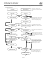
8.2 Operation Using the Positioning Mode
Operation Based on the External Start Signal Selection
(1) Homing
Controller
The positioning mode consists of
"Operation from the teaching
pendant," "Operation using the PC
software," and "Operation based on
the external start signal selection."
This section explains the last
method.
External Device
↓
↓
Power ON
Power ON
↓
↓←
READY output
⇒
READY signal ON
READY signal
confirmed?
N
Y
↓
→
Once the READY signal is ON, the
READY lamp (green) on the
controller front panel lights up.
Set all Position No.
command to
OFF (0).
↓
N
↓
External start input
Start signal
confirmed?
⇐
Homing is performed when all
position number inputs from the
external device are OFF ("0")
and the start signal is input.
Start signal ON
↓
Homing Start
↓
←
After homing is completed, the
positioning complete signal is output
and the controller goes
into a wait stage.
Homing Complete
↓
↓
Positioning Complete Signal
Position Complete
Signal ON
⇒
ALARM signal
confirmed?
Y
↓
N
NOTE:
By homing, for later operations, commands from the external device have priority. When switching over to an operation from
the teaching pendant or using a PC software, perform homing after cutting the power once.
Page 29
DS
8. Moving the Actuator
Controller
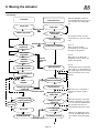
(2) Positioning
Controller
External Device
Power ON
Power ON
↓
READY signal ON
↓
READY output
⇒
READY signal
confirmed?
↓Y
→
Position No.
confirmed?
→
Start signal
confirmed?
↓Y
Y
Homing
complete?
↓N
↓
Position No. input
⇐
Note 2::
When there is no data in the
designated position number, the
signal is disregarded.
↓
←
↓
↓
Positioning
complete confirmed?
Move
complete
↓
→
Y
N
↓Y
Positioning complete
signal ON
Position
complete output
N
Note 3::
If homing has not been performed
and a position is designated and a
start signal input, the actuator will
home first and then, move to the
position.
Start signal ON
→
↓
Move to command
position
Controller
abnormal?
Note 1::
When a position number
greater than 501 is designated,
the signal is disregarded.
Position No. command
External
operation
input
Homing Complete
N
The program number from the
external device is input as a BCD
code.
↓Y
N
→
N
I/O processing
↓
N
←
When the READY signal turns
ON, the READY lamp (green) on
the controller front panel lights
up.
Emergency stop
signal confirmed?
Y
↓
Servo OFF
I/O processing
↓
Emergency stop
switch ON?
Y
↓
Emergency stop
signal ON
←
↓
ALARM signal
confirmed?
↓
↓Y
ALARM signal ON
ALARM processing
ALARM output
↓
Page 30
←
When the move is completed, a
positioning complete signal is
output.
When an emergency stop signal
N from the external device is input
or, if the controller malfunctions,
the controller turns the servo
OFF (READY lamp turns OFF).
N
When the ALARM signal turns
ON, the ALARM lamp (red) on
the controller front panel lights
up.
DS
8. Moving the Actuator
Controller
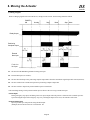
(3) Timing of Signals
When exchanging signals with an external device, timing becomes critical. See the timing charts that follow::
POWER
ON
Homing
Stop
Move
Stop Move
Ready Output
Positioning
Complete Output
External
Start Input
Position
No. Input
T1: The time from the READY signal ON to homing start input.
T2: External start input (over 30msec).
T3: The time from the the previous positioning complete output ON to when the external start signal input can be entered (50msec).
T4: The time it takes from external start input ON to positioning complete output OFF.
T5: The time it takes to input from position number input to external start.
* The interchange timing of each position number input is effective after receiving external start input.
* Alarm Output
During emergency stop input, and during CPU reset input, outputs when the protective function of the controller operates.
Upon releasing the input of the emergency stop, or by releasing the input of CPU reset, the controller will restart.
* Position Number Input
Input is possible up to 500 positions using the BCD input.
(Example): No.100+No.20+No.4+No.1= Position No. 125
Page 31
DS
8. Moving the Actuator
Controller
(4) Timing for Position No. Switching
Position No.
Input
A
External Start
Input
Positioning Complete
Output
A:
Position 1 execution start
B:
Position 2 execution start
B
Moving
Moving
The timing for position number shifting is the time from after the position presently being executed is
completed until the next external start input (start signal) can be input.
Page 32
8. Moving the Actuator
DS
Controller
(5) Timing of Motion Using a Hold Signal
Position
Input
Actuator
movement
Slowing to a stop
Movement start
The servo actuator is slowed to a stop by turning the hold signal ON while the actuator is moving and starts up
again by turning the hold signal OFF.
Page 33
DS
8. Moving the Actuator
Controller
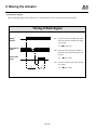
(6) Movement in Random Sequence
To move the actuator in a random order, select the position number and input external start signal for each movement.
Position
No.
Acceleration
Velocity
Position
1
0.3
100
50.000
2
0.3
100
200.000
1
3
0.3
200
100.000
4
4
0.3
200
250.000
5
X.X
XXX
XXX.XXX
6
0.3
300
150.000
7
0.3
300
150.000
8
X.X
XXX
XXX.XXX
9
X.X
XXX
XXX.XXX
·
·
·
·
·
·
·
·
·
·
·
·
492
X.X
XXX
XXX.XXX
493
X.X
XXX
XXX.XXX
494
0.3
200
150.000
495
0.3
200
380.000
496
0.3
200
400.000
497
0.3
200
200.000
498
0.3
100
250.000
499
X.X
XXX
XXX.XXX
500
X.X
XXX
XXX.XXX
Select Position Number
External Start Input
2
Movement Complete
Positioning Complete ON
Page 34
3
5
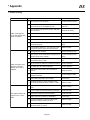
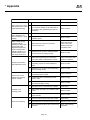
9. Error Code list
DS
Controller
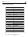
When an error occurs, the alarm LED (red color ) on the controller's front side will light up. At the same time, the I/O alarm
output will turn ON and the READY output will turn OFF.
Error Code List
Erro r Co d e
A1
Erro r Name
Exp lanatio n
Exte rnal Inte rrup t Erro r
1. Mo to r o ve r curre nt
2. Ove r re g e ne rative curre nt (o ve r ne g ative lo ad )
3. Drive r o ve rhe at
A2
Mo to r Ove rlo ad Erro r
Me chanical o ve rlo ad o f mo to r
A3
De viatio n Erro r
Mo to r is unab le to p e rfo rm p ro p e rly d ue to me chanical o ve rlo ad
A4
So ftware Limit Erro r
Exce e d e d so ftware limit
A5
Po le Se nse Erro r
Unab le to se nse p o le
B0
No Pro g ram Erro r
Pro g ram d o e s no t e xist
B1
Pro g ram Exe cutio n Erro r
Exe cutio n o f a curre ntly e xe cuting p ro g ram
B2
Pro g ram Ove r Erro r
Numb e r o f tasks e xce e d s tho se se t as p arame te rs
B3
Do ub le Sub ro utine Numb e r Erro r
Two o r mo re o f the same sub ro utine numb e r are use d
B4
Do ub le Tag Numb e r Erro r
Two o r mo re o f the same tag numb e r are use d
B5
Und e fine d Sub ro utine Numb e r
Sub ro utine numb e r is no t d e fine d
B6
Und e fine d Tag Numb e r
Tag numb e r is no t d e fine d
B7
Sub ro utine Pair Erro r
BGSR and EDSR are no t the same q uantity
B8
Ste p 1 BGSR Erro r
Ste p 1 is a BGSR Erro r
B9
DO, EDDO Pair Erro r
DO and EDDO are no t the same q uantity
BA
DO Ne st Ove r Erro r
DO was use d mo re than 15 time s
BB
IF Pair Erro r
IF and ELSE are no t the same q uantity
BC
ELSE Erro r
ELSE was use d in a p lace which was no t b e twe e n IF and EDIF
C0
No Ho ming Erro r
Ho ming was no t p e rfo rme d b e fo re running actuato rs
C1
Po int Data Erro r
Atte mp t has b e e n mad e to e xe cute d unre g iste re d p o int d ata
C2
Axis Do ub le Exe cutio n Erro r
Mo ve co mmand g ive n to axis curre ntly mo ving
C3
So ftware Limit Erro r
So ftware limit e xce e d e d in p ro g ram
S mo tio n p e rce nt ws se t o utsid e the rang e o f 0 ~ 50%
CE
S Mo tio n Pe rce nt Erro r
D0
Acce le ratio n Erro r
Acce le ratio n e xce e d s limits
D1
No Ve lo city Erro r
Ve lo city has no t b e e n se t
D2
Ove rrid e Erro r
D4
Axis Patte rn Erro r
Ove rrid e was se t o utsid e the rang e o f 1 ~ 100%
Axis p atte rn was no t se t co rre ctly. Disp lays D4 also fo r C1 (p o int d ata
e rro r)
Axis numb e r was se t o utsid e the rang e o f 1 ~ 8
D5
Axis Numb e r Erro r
D7
Pro g ram Numb e r Erro r
Pro g ram numb e r e xce e d s the limit
D8
Po sitio n Numb e r Erro r
Po sitio n numb e r e xce e d s the limit
D9
Po int Numb e r Erro r
Ne g ative numb e r was inp ut in the p o int numb e r
Flag is no t assig ne d co rre ctly
DA
Flag Numb e r Erro r
DB
Variab le Erro r
Variab le is no t assig ne d co rre ctly
DC
Dig its Ove r Erro r
Assig ne d numb e r e xce e d s 8 d ig its (b inary 32 b its)
DD
Divisio n (0) Erro r
Re sult o f the d ivisio n is "0"
DF
Task Le ve l Erro r
Task le ve l was se t o utsid e o f the rang e o f 1 ~ 5
E0
Und e fine d Co mmand Erro r
Atte mp te d to e xe cute und e fine d co mmand
E1
Sub ro utine Ove r Ne sting Erro r
Ne sting o f mo re than 15 sub ro utine s
E2
Sub ro utine Und e r Ne sting Erro r
EXSR and EDSR are no t making a p air
E3
Co ntro lling Co lumn Erro r
Use o f co nd itio n is no t co rre ct
EG
EMG Erro r
Eme rg e ncy (Eme rg e ncy Sto p ) was asse rte d
F0
Inte rrup t Erro r
Mo to r CPU and Inte rrup t manag e me nt d o no t match
Note:
An "E" appears at the head of the error code, followed by 3 digits.
Page 35
DS
10. Maintenance
Controller
To ensure safe and trouble-free operation of your system, a regular maintenance and inspection program should be
implemented. Be sure to turn OFF the power before initiating any maintenance or inspection work. An inspection is
recommended at least once every 6 to 12 months. However, depending on the environment, a more frequent inspection
schedule may be advisable.
(1) Inspection Guidelines
• Check and make sure that the power supply to your controller is within the specification range (DC24V±10%).
• Check the controller vents and clean any accumulated dirt or dust.
• Check the controller cable (controller → axis) and make sure that there are no loose screws or disconnections.
• Check for loose controller mounting screws. Tighten if necessary.
• Check each cable (axis cables, general I/O cables, system I/O cables, power supply cable).
Check for loose connections, damage, or excessive wear. Replace if necessary.
(2) Recommended Spare Parts
Should a breakdown occur, even if it is discovered early, repairs can not be done if there are no spare parts.
It is advisable to keep a small supply of spare parts, especially for those parts that wear down with use.
The following spare parts are recommended:
• Cables
• Batteries
(Ni-Cd batteries have a general shelf life of about 6 years but this varies depending on use conditions and environment)
(3) Memory Backup
When the controller is fully charged, the backup memory is guaranteed for 3 months. In actuality, the backup memory
is not erased for 6-8 months but if the controller is to be left for a long period (more than 3 months) without having
current run through it, please take precautions to save your program, position data, and parameters. To fully charge the
controller if it does not contain any data, you will need to leave the controller with the power ON for 3 days. If the
memory is erased, the system's preset parameters will be set but the actuator will not run properly in this condition.
Page 36
DS
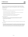
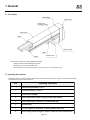
1. General
Slider Type
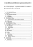
1.1 Part Names
Dust shield mounting bolt
Front cover
Dust shield
Slider cover
Slider
Side cover
Dust shield mounting bolt
Side cover
mounting bolt
Motor housing
Encoder cover
Side cover
Base
Side cover mounting bolt
Cable
Please note the following when handling the actuator.
• To handle the actuator, support it from underneath or grasp the area around the side cover mounting bolts.
• Do not place excessive load on the cable.
• Do not place heavy loads on the encoder cover, slider cover or other plastic parts.
1.2 Operating Environment
Install the actuator in a place where the operator can work without protective gear. See the table below for specific operating
environment criteria.
N o.
Operating Conditions
1
Ambient temperature 0~40°C
2
Relative humidity 35~90%
3
Avoid direct sunlight
4
Avoid exposure to water, cutting oil and other liquids
5
Avoid exposure to corrosive or combustible gas
6
Minimal dust
7
Do not subject to vibrations or shock greater than 0.5G
8
Avoid strong electromagnetic waves, ultraviolet rays and radiation
Page 37
DS
2. Installation
Slider Type
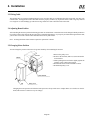
2.1 Installing the Actuator
(SA4, SA5 Type)
Mount the actuator to a machined surface or one of comparable precision. Install the actuator as shown below.
The actuator base and lower surface are parallel to the
guide. When travelling precision is required, use this
surface as a reference to mount the actuator. For basic
mounting, use the four mounting holes located on the
upper surface of the actuator.
The reamer holes on the back side for positioning pin may be used as needed.
Machine Type
When opposite
material is copper
DS-SA4
DS-SA5
When opposite
material is aluminum
M3X35
M4X40
M4X45
For mounting bolts, depending on the material of the foundation side,
use the bolt with hexagonal holes as indicated below.
Machine Type
Reamer Hole
Depth
DS-SA4
φ3H10
Under 5mm
DS-SA5
φ4H10
Under 5mm
DS-SA6
φ4H10
Under 5mm
Rest the actuator on the mounting surface and check
to see that a 0.1mm thickness gauge cannot be inserted
at the four mounting holes. If the bolts go in a steel
surface with tapped holes, then use hexagon sockets
with length shown in and if the surface is a light
metal, use the length in .
Page 38
2. Installation
DS
Slider Type
(S6 Type)
On the base of the actuator, you can use the two mounting holes at the motor end and the tapped holes on the
underside of the base but please make note of the following.
Back Side Mounting Tap Holes
Machine Type
Bolt Siz e
Tap Depth
Engagement depth
DS-SA4
M3
5mm
Over 3mm Under 5mm
DS-SA5
M4
7mm
Over 4mm Under 7mm
DS-SA6
M5
9mm
Over 5mm Under 9mm
Suggested Tightening Torque
Bolt Siz e
When the bolt surface is
steel
When the bolt surface
is aluminum
M3
1.6N • m (0.16kgf • m)
1.1N • m (0.11kgf • m)
M4
3.7N • m (0.38kgf • m)
2.3N • m (0.23kgf • m)
M5
7.5N • m (0.77kgf • m)
4.3N • m (0.44kgf • m)
2.2 Attaching the Workpiece
Use the four tapped holes at the top of the slider to
attach the workpiece.
Page 39
DS
2. Installation
Slider Type
To attach the workpiece, select bolts that will have the engagement lengths indicated in the table below and adjust the
length of the washer if necessary. Ma ke sure that the workpiece does not touch the slider cover , and note the following:
Machine Type
Slider Mounting Area
Engagement Depth
DS-SA4
M3 depth 7mm
Over 3mm Under 7mm
DS-SA5
M4 depth 9mm
Over 4mm Under 9mm
DS-SA6
M5 depth 9mm
Over 5mm Under 9mm
Bolt Siz e
When the bolt surface is
steel
When the bolt surface
is aluminum
M3
φ (0.16kgf • m)
1.6N • m
1.1N • m (0.11kgf • m)
M4
φ (0.38kgf • m)
3.7N • m
2.3N • m (0.23kgf • m)
M5
φ (0.77kgf • m)
7.5N • m
4.3N • m (0.44kgf • m)
2.3 Wiring Cable
The actuator cable is resistant to bending fatigue but it is not robot cable. Avoid housing the cable in movable wire duct with a small
radius. In an application where the cable cannot be anchored, try to place the cable so that it sags only under its own weight or use
self-standing type cable hose as large radial wire duct to limit the load on the cable.
2.4 Adjusting Home Position
After installing the actuator, perform the homing operation to confirm home. Home direction can be changed with the parameters. If
you allow a large offset amount, the moving range is limited by that amount. If you specify an offset amount greater than 1mm, you
will have to reset the software limit and reduce the stroke by that amount.
Note: To change the home offset amount requires the optional PC software.
2.5 Load on the Actuator
Do not exceed the load shown in the specification table as indicated in Chapter 4 of this manual. Please note in particular the
slider moment and allowable overhang length and the load weight.
The base of the actuator warps easily when it is used with an overhang so please keep the Ma and Mc moments under 1/2 of the
rated value.
Page 40
3. Maintenance
DS
Slider Type
3.1 Maintenance Schedule
Perform maintenance work according to the schedule below.
Maintenance Checkpoints
Visual
inspection
Check for loose
dust shield
Check
interior
Lubrication
Start operation
After 1 month of operation
After 6 months of operation
Semiannually therafter
Annually thereafter
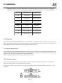
Note 1: The above schedule assumes running time is 8 hours per day. When running time is high such as
continuous day and night operation, shorten the maintenance intervals as required.
Note 2: The motor housing supports the ball screw, so please do not disassemble. The end cover supports the
ball screw so please do not remove it. Do not remove the encoder cover as this contains precision
equipment.
3.2 Cleaning the Exterior
1.
2.
3.
4.
5.
Wipe off dirt with a soft cloth.
Wipe the dust shield gently so that it does not bend.
Do not use strong compressed air on the actuator as this may force dust into the crevices.
Do not use petroleum-based solvents on plastic parts or painted surfaces.
If the unit is badly soiled, apply a neutral detergent or alcohol to a soft cloth and wipe lightly.
Page 41
DS
3. Maintenance
Slider Type
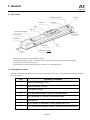
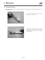
3.3 Inspecting the Interior
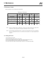
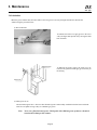
(1) Removing the cover
Turn the power OFF. Using a 1.5mm hexagonal
wrench, remove the cover as shown in the picture
and visually inspect the interior.
(2) Visual check of the interior
Make a visual check of the interior to see if there is
any dust or foreign matter in the unit and check the
lubrication. Even if the grease you see around the
parts is brown, the lubrication is fine as long as the
travelling surface appears shiny.
Page 42
3. Maintenance
DS
Slider Type
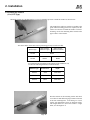
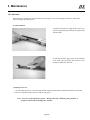
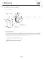
3.4 Lubrication
When the grease contains dust, becomes dull in color or begins to wear away through extended use, lubricate the
actuator using the procedure below.
(1) How to lubricate
To lubricate the ballscrew, apply grease to the screw
with your finger then spread it out by moving the slider
back and forth.
To lubricate the slider, apply grease to the underside
of the slider with your finger, then spread it out by
moving the slider back and forth.
(2) What grease to use
IAI uses lithium grease No. 2. There are other brands of grease commerciallly available for the ballscrew and slider.
These are acceptable as long as they are a lithium-type grease.
Note: Never use a fluorine-based grease. Mixing this with a lithium grease produces a
chemical reaction which damages the actuator.
Page 43
DS
3. Maintenance
Slider Type
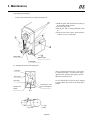
(3) Replacing the cover
Inside the slider cover is a spring that allows it to follow along the dust shield. Lift the shield up from the
bottom and attach the side cover.
If the shield is not straight, move the slider slightly to
straighten out the shield. Or, lift the shield gently to
straighten it out. Tighten the bolts on the side cover.
The torque should be for a small plus screw (0.6Nm, 6
kgcm).
After completing the inspection, replace the cover.
Page 44
3. Maintenance
DS
Slider Type
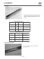
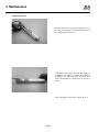
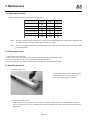
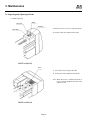
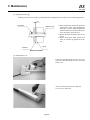
3.5 Checking the Dust Shield
The dust shield is made from stainless steel and is adjusted at the time of shipment. If the shield slackens with use, make the
following adjustments.
Move the slider to the end. Loosen the screw at the
front end with a 1.5mm wrench.
Pull the shield just enough to make it taut. Move the
slider manually to make sure it moves easily. If there
is resistance in the movement, there is too much tension in the shield.
Page 45
DS
1. General
Arm Type
1.1 Part Names
Motor bracket
Pulley cover
Screw cover
mounting screws
Screw cover
Slider
Motor housing
Cable
Encoder cover
Base
Please note the following when handling the actuator.
• Support the base when handling the actuator.
• Do not place excessive load on the cable.
• Do not place heavy loads on the pulley cover, encoder cover or other plastic parts.
1.2 Operating Environment
Install the actuator in a place where the operator can work without protective gear. Specific criteria for the operating
environment are shown in the table below.
N o.
Operating Conditions
1
Ambient temperature 0~40°C
2
Relative humidity 35~90%
3
Avoid direct sunlight
4
Avoid exposure to water, cutting oil and other liquids
5
Avoid exposure to corrosive or combustible gas
6
Minimal dust
7
Do not subject to vibrations or shock greater than 0.5G
8
Avoid strong electromagnetic waves, ultraviolet rays and radiation
Page 46
2. Installation
DS
Arm Type
2.1 Installing the Actuator
Mount the actuator to a machined surface or one of comparable precision.
This actuator has a built-in brake. Connect the controller to the unit, then release the brake with the brake
switch. After releasing the brake, pull the slider to the
stroke end. Turn off the controller power before proceeding to the next step.
Remove the four mounting screws from the screw cover.
(The cover can be removed using a 1.5mm hexagonal
wrench).
Rest the actuator on the mounting surface and check
to see that a 0.1mm thickness gauge cannot be inserted
at the four mounting holes.
Affix the actuator using the mounting holes in the base.
If the bolts go into a steel surface, then use hexagon
sockets with the length shown in (1) and if the surface
is a light metal, use the length in (2).
After mounting the actuator, reattach the screw cover.
Page 47
Actuator
(1)
(2)
DS-A6
M5x40
M5x15
DS-A5
M4X8
M4X12
DS-A4
M3X8
M3X12
DS
2. Installation
Arm Type
2.2 Attaching the Workpiece
Tapped holes for
mounting workpiece
Use the four tapped holes at the top of the
slider to attach the workpiece.
Slider
There are 4 M4 screws for attaching the workpiece to the slider. To ensure the slider does not become deformed
when the workpiece is attached, check to make sure the surface where the workpiece rests is flat. A deformity in the
slider causes stiff movement and shortens the life of the actuator.
Do not exceed the load indicated in the specification tables at
Part 4. Please note in particular the slider moment, allowable
overhang length and the load weight.
Keep the overhang at the upper portion of the workpiece to the
measurements below to prevent interference between the screw
cover and workpiece.
DS-A6 Type
DS-A5 Type
DS-A4 Type
Slider
Page 48
A=70mm
A=65mm
A=53mm
2. Installation
DS
Arm Type
2.3 Wiring Cable
The actuator cable is resistant to bending fatigue but it is not robot cable so avoid housing the cable in movable wire duct with
a small radius. In an application where the cable cannot be properly anchored, try to place the cable so that it sags only under its
own weight or use self-standing type cable hose as large radial wire duct to limit the load on the cable.
2.4 Adjusting Home Position
After installing the actuator, perform the homing operation to confirm home. Home direction can be changed with the parameters.
If you allow a large offset amount, the moving range is limited by that amount. If you specify an offset amount greater than 1mm,
you will have to reset the software limit and reduce the stroke by that amount.
Note: To change the home offset amount requires the optional PC software.
2.5 Changing Motor Position
You can change the position of the motor for greater flexibility when installing the actuator.
1. Remove the pulley cover.
2. Remove the four bolts (M4 x 25) used to mount the
motor bracket.
3. While pushing the motor bracket lightly against the
actuator, rotate it and set the position.
4. Reattach the motor bracket with M4 x 25 bolts.
5. Reattach the pulley cover.
Actuator
M4x25
Motor bracket
M3
Pulley cover
Changing the motor position will affect the home position so always make sure to readjust home. (For a ball screw lead of
6mm, home will move 1.5mm for every 90° change).
Page 49
DS
3. Maintenance
Arm Type
3.1 Maintenance Schedule
Perform maintenance work according to the schedule below.
Visual
Inspection
Internal
Check
Lubrication
Start of operation
After 1 month of operation
After 6 months of operation
After 1 year of operation
Semiannually thereafter
Annually thereafter
Note 1: The above schedule assumes running time is 8 hours per day. When running time is high such as continuous day
and night operation, shorten the maintenance intervals as required.
Note 2: The end cover supports the ball screw so please do not remove it. Do not remove the encoder cover as this contains
precision equipment
3.2 Cleaning the Exterior
1. Wipe off dirt with a soft cloth.
2. Do not use strong compressed air on the actuator as this may force dust does into the crevices.
3. Do not use petroleum-based solvents on plastic parts or painted surfaces.
4. If the unit is badly soiled, apply a neutral detergent or alcohol to a soft cloth and wipe lightly.
3.3 Inspecting the Interior
(1) Removing the cover
Turn the power OFF. Using a 1.5mm hexagonal
wrench, remove the cover as shown in the
picture and visually inspect the interior.
(2) Visual check of the interior
Make a visual check of the interior to see if there is any dust or foreign matter in the unit and check the lubrication. Even if the grease you see around the parts is brown, the lubrication is fine as long as the travelling surfaces
appear shiny.
Page 50
3. Maintenance
DS
Arm Type
3.4 Lubrication
When the grease contains dust, becomes dull in color or begins to wear away through extended use, lubricate the
actuator using the procedure below.
(1) How to lubricate
To lubricate the ball screw, apply grease to the screw
with your finger then spread it out by moving the slider
back and forth.
Apply grease here
To lubricate the slider, remove the return cover attached to the guide block and apply grease directly on
the bearing.
Return cover
(2) What grease to use
IAI uses lithium grease No. 2. There are other brands of grease commerciallly available for the ball screw and slider.
These are acceptable as long as they are a lithium-type grease.
Note:
Never use a fluorine-based grease. Mixing this with a lithium grease produces a chemical
reaction which damages the actuator.
Page 51
DS
3. Maintenance
Arm Type
3.5 Inspecting and Replacing the Timing Belt
(1) Removing the belt cover
Timing belt
Actuator
Remove the pulley cover as shown at left and
inspect the timing belt.
M3
Motor bracket
Pulley cover
(2) Inspecting the timing belt
The durability of the timing belt is largely dependent on the operating conditions. It is difficult to give an absolute rule
regarding when to replace the timing belt but generally the belt has a lifetime of so many millions of rotations. The more
practical approach is to replace the belt if any of the following conditions occur.
• The belt end or belt teeth have worn away.
• There are cracks in or other damage to the belt or teeth.
• The belt breaks.
If you need to replace the belt, please contact IAI.
Page 52
3. Maintenance
DS
Arm Type
(3) Replacing the timing belt
Follow the procedure below to replace the timing belt.
Mark the pulley and motor bracket so that you
do not change home position.
Loosen the four bolts.
Put the new belt on while pushing the motor
up.
After the new belt is in place, do the same procedure in reverse to reassemble.
Motor pulley
Motor bracket
Timing belt
(4) Adjusting the tension of the timing belt
Large pulley
After you change the timing belt, it is necessary
to readjust the tension. As shown in the upper
diagram at left, push the motor pulley up, then
adjust the tension and set it.
Motor bracket
Motor pulley
To put the belt on, match
it to the marked position.
Hexagonal bolt
(M4x20)
3kgf
Check tension
δ = 1mm
F=100gf
Page 53
Use the method shown in the left lower diagram
to check whether the tension of the timing belt is
suitable.
DS
3. Maintenance
Arm Type
3.6 Inspecting and Adjusting the Brake
(1) Brake inspection
Set screw
Stator
Armature
Remove the screw cover to inspect the brake.
Inner driver
Visually check the condition of the brake.
DS5 TYPE (DS-A5)
Seal
Peel off the seal to inspect the brake.
Visually check the condition of the brake.
Note: When the motor is folded backwards (S
type), you must change the direction to the
right or the left.
DS4 TYPE (DS-A4)
Page 54
DS
3. Maintenance
Arm Type
(2) Adjusting the brake gap
Normally, the inner driver requires no maintenance but if adjustments are necessary, use the following procedure.
0.5
Inner driver
Ballscrew axis
Armature
We recommend the actuator be placed on
a horizontal surface when adjusting the
brake gap. If you are doing the adjustment
with the actuator in a vertical position, first
move the slider to the stroke end.
Release the brake and loosen the two set
screws.
Set the inner driver about 0.5mm from
where it would hit up against the armature.
Stator
Brake Cross Section
(3) Attaching the cover
Follow the procedure used to remove the cover
in reverse order and reattach the screw cover and
pulley cover.
After you finish the inspection, replace the
cover as it was at the start.
Page 55
1. Specifications for the SlideType
DS
1.1 High Speed Type DS-SA6H
Specifications
Model
DS-SA6H
Stroke
mm
W
mm/sec
N(kgf)
mm
kg
Rated Output
Rated Speed
Rated Thrust
Repeatability
Unit Weight
50
50
100
100
150
150
200
200
250
250
300
300
30
400
400
450
450
800
1.3
1.5
1.7
Motor
24.2(2.4)
±0.05
1.9
2.1
2.3
2.5
AC Servo Motor
AC motor attached 192P/R
Structure of Main Component
Encoder
350
350
2.7
2.9
500
500
550
550
600
600
760
640
540
3.1
3.3
3.5
Signal wave
A,B,Z Phase
A Phase
Input voltage +5V
B Phase
C Phase
(Homing pulse: 1 pulse ¼ rotation)
Ø10mm Lead 12mm Rolled thread C10 Backlash 0.1mm or less
Direct recirculating ball bearing: Hardened carbon steel ground track
Ballscrew
Guide
Motor/Ballscrew
Connection
Integrated motor axis and ballscrew axis
Exclusive extruded aluminum (A6N01S-T5 equivalent) White alumite treated
Special steel alloy
Exclusive extruded aluminum (A6063S-T5 equivalent) White alumite treated
Stainless steel
Aluminum die-cast Baked finish
B a se
Slider
Side Cover
Dust Shield
Motor Housing
Encoder Cover,
Front Cover,
Slide Cover
Polyacetal plastic
11-conductor composite cable 5m (standard length)
Ballscrew: Lithium type grease
Grease
Guide: Shell Albania Grease No. 2, Mobil Mobilux No. 2 or equivalent
Model
DS-SA6H 50
100
150 200
250
300
350 400 450 500 550
Maximum Thrust (1)
N(kgf)
72(7.3)
Payload (2, 3)
kg w
Horizontal: 6kg
Vertical: 1.5kg
Cable
Overhang Load
Length L (5)
mm
5000km life expectancy
Ma: 8.9(0.9) Mb: 12.7(1.3) Mc: 18.6(1.9)
Ma 220 or less
1: At a speed of 10mm/sec for 5 seconds.
2: Even load distribution on the slider. (When designing work, consider load
moment). Fix base securely to a flat, strong frame.
3: At an acceleration of 0.3G and a speed of 800mm/sec.
4: Direction of load moment is:
Mb direction
Mb, Mc 220 or less
5: When the center of gravity for the attached
object is ½ the overhang length.
40
N·m
(kgf·m)
Ma, Mc moment
Standard location of offeset
L
Mc direction
Ma direction
L
Application Limit
Moment (2, 4)
600
M b, Mc direction
Ma direction
Page 56
1. Specifications for the SlideType
DS
1.2 Medium Speed DS-SA6M
Specifications
Model
DS-SA6M
Stroke
mm
W
mm/sec
N(kgf)
mm
kg
Rated Output
Rated Speed
Rated Thrust
Repeatability
Unit Weight
50
50
100
100
150
150
200
200
250
250
300
300
30
400
400
450
450
400
1.3
1.5
48.4(4.9)
±0.02
1.9
2.1
2.3
2.5
AC Servo Motor
1.7
Motor
AC motor attached 192P/R
Structure of Main Component
Encoder
350
350
2.7
2.9
500
500
550
550
600
600
380
320
270
3.1
3.3
3.5
Signal wave
A,B,Z Phase
A Phase
Input voltage +5V
B Phase
C Phase
(Homing pulse: 1 pulse ½ rotation)
Ø10mm Lead 6mm Rolled thread C10 Backlash 0.1mm or less
Direct recirculating ball bearing: Hardened carbon steel ground track
Ballscrew
Guide
Motor/Ballscrew
Connection
Integrated motor axis and ballscrew axis
Exclusive extruded aluminum (A6N01S-T5 equivalent) White alumite treated
Special steel alloy
Exclusive extruded aluminum (A6063S-T5 equivalent) White alumite treated
Stainless steel
Aluminum die-cast Baked finish
B a se
Slider
Side Cover
Dust Shield
Motor Housing
Encoder Cover,
Front Cover,
Slide Cover
Polyacetal plastic
11-conductor composite cable 5m (standard length)
Ballscrew: Lithium type grease
Grease
Guide: Shell Albania Grease No. 2, Mobil Mobilux No. 2 or equivalent
Model
DS-SA6M 50
100
150 200
250
300
350 400 450 500 550
Maximum Thrust (1)
N(kgf)
145(14.7)
Payload (2, 3)
kg w
Horizontal: 12kg
Vertical: 3kg
Cable
Overhang Load
Length L (5)
mm
5000km life expectancy
Ma: 8.9(0.9) Mb: 12.7(1.3) Mc: 18.6(1.9)
Ma 220 or less
1: At a speed of 10mm/sec for 5 seconds.
2: Even load distribution on the slider. (When designing work, consider load
moment). Fix base securely to a flat, strong frame.
3: At an acceleration of 0.3G and a speed of 400mm/sec.
4: Direction of load moment is:
Mb direction
Mb, Mc 220 or less
5: When the center of gravity for the attached
object is ½ the overhang length.
40
N·m
(kgf·m)
Ma, Mc moment
Standard location of offeset
L
Mc direction
Ma direction
L
Application Limit
Moment (2, 4)
600
M b, Mc direction
Ma direction
Page 57
DS
1. Specifications for the SlideType
1.3 Low Speed High Thrust DS-SA6L
DS-SA6L
mm
W
mm/sec
N(kgf)
mm
kg
Rated Output
Rated Speed
Rated Thrust
Repeatability
Unit Weight
50
50
100
100
150
150
200
200
250
250
350
350
400
400
450
450
200
1.3
1.5
1.7
Motor
96.8(9.8)
±0.02
1.9
2.1
2.3
2.5
AC Servo Motor
AC motor attached 192P/R
Structure of Main Component
Encoder
300
300
30
2.7
2.9
500
500
550
550
600
600
190
160
135
3.1
3.3
3.5
Signal wave
A,B,Z Phase
A Phase
Input voltage +5V
B Phase
C Phase
(Homing pulse: 1 pulse 1 rotation)
Ø10mm Lead 3mm Rolled thread C10 Backlash 0.1mm or less
Direct recirculating ball bearing: Hardened carbon steel ground track
Ballscrew
Guide
Motor/Ballscrew
Connection
Integrated motor axis and ballscrew axis
Exclusive extruded aluminum (A6N01S-T5 equivalent) White alumite treated
Special steel alloy
Exclusive extruded aluminum (A6063S-T5 equivalent) White alumite treated
Stainless steel
Aluminum die-cast Baked finish
B a se
Slider
Side Cover
Dust Shield
Motor Housing
Encoder Cover,
Front Cover,
Slide Cover
Cable
Grease
Model
Maximum Thrust (1)
Payload (2, 3)
Polyacetal plastic
11-conductor composite cable 5m (standard length)
Ballscrew: Lithium type grease
Guide: Shell Albania Grease No. 2, Mobil Mobilux No. 2 or equivalent
DS-SA6L 50
100
150
200
250
300
350 400 450 500 550
N(kgf)
290(29.5)
kg w
Horizontal:12kg
Vertical: 6kg
N·m
(kgf·m)
Overhang Load
Length L (5)
mm
5000km life expectancy
Ma: 8.9(0.9) Mb: 12.7(1.3) Mc: 18.6(1.9)
Ma 220 or less
1: At a speed of 10mm/sec for 5 seconds.
2: Even load distribution on the slider. (When designing work, consider load
moment). Fix base securely to a flat, strong frame.
3: At an acceleration of 0.2G and a speed of 200mm/sec.
4: Direction of load moment is:
Mb, Mc 220 or less
5: When the center of gravity for the attached
object is ½ the overhang length.
Ma, Mc moment
Standard location of offeset
Mb direction
L
Mc direction
Ma direction
L
Application Limit
Moment (2, 4)
600
40
Specifications
Model
Stroke
Mb, Mc direction
Ma direction
Page 58
1. Specifications for the SlideType
DS
1.4 High Speed DS-SA5H
Specifications
Model
DS-SA5H
Stroke
mm
W
mm/sec
N(kgf)
mm
kg
Rated Output
Rated Speed
Rated Thrust
Repeatability
Unit Weight
50
50
100
100
150
150
200
200
250
250
300
300
20
400
400
450
450
800
1.2
1.3
1.4
Motor
500
500
760
16.7(1.7)
±0.05
1.5
1.6
1.7
1.8
AC Servo Motor
AC motor attached 192P/R
Structure of Main Component
Encoder
350
350
1.9
2.0
2.1
Signal wave
A,B,Z Phase
A Phase
Input voltage +5V
B Phase
C Phase
(Homing pulse: 1 pulse ¼ rotation)
Ø10mm Lead 6mm Rolled thread C10 Backlash 0.1mm or less
Direct recirculating ball bearing: Hardened carbon steel ground track
Ballscrew
Guide
Motor/Ballscrew
Connection
Integrated motor axis and ballscrew axis
Exclusive extruded aluminum (A6N01S-T5 equivalent) White alumite treated
Special steel alloy
Exclusive extruded aluminum (A6063S-T5 equivalent) White alumite treated
Stainless steel
Aluminum die-cast Baked finish
B a se
Slider
Side Cover
Dust Shield
Motor Housing
Encoder Cover,
Front Cover,
Slide Cover
Polyacetal plastic
11-conductor composite cable 5m (standard length)
Ballscrew: Lithium type grease
Grease
Guide: Shell Albania Grease No. 2, Mobil Mobilux No. 2 or equivalent
Model
DS-SA5H 50
100
150 200
250
300
350 400 450 500
Maximum Thrust (1)
N(kgf)
33.3(3.4)
Payload (2, 3)
kg w
Horizontal: 4kg
Vertical: 1kg
Cable
Overhang Load
Length L (5)
mm
5000km life expectancy
Ma: 4.9(0.5) Mb: 6.8(0.7) Mc: 11.7(1.2) Mc:7.8(0.8)
Ma 150 or less
1: At a speed of 10mm/sec for 5 seconds.
2: Even load distribution on the slider. (When designing work, consider load
moment). Fix base securely to a flat, strong frame.
3: At an acceleration of 0.3G and a speed of 800mm/sec.
4: Direction of load moment is:
Mb, Mc 150 or less
5: When the center of gravity for the attached
object is ½ the overhang length.
39
N·m
(kgf·m)
Ma, Mc moment
Standard location of offeset
Mb direction
L
Mc direction
Ma direction
L
Application Limit
Moment (2, 4)
Mb, Mc direction
Ma direction
Page 59
1. Specifications for the SlideType
DS
1.5 Medium Speed DS-SA5M
Specifications
Model
DS-SA5M
Stroke
mm
W
mm/sec
N(kgf)
mm
kg
Rated Output
Rated Speed
Rated Thrust
Repeatability
Unit Weight
50
50
100
100
150
150
200
200
250
250
350
350
400
400
450
450
400
1.2
1.3
1.4
Motor
500
500
380
33.3(3.4)
±0.02
1.5
1.6
1.7
1.8
AC Servo Motor
AC motor attached 192P/R
Structure of Main Component
Encoder
300
300
20
1.9
2.0
2.1
Signal wave
A,B,Z Phase
A Phase
Input voltage +5V
B Phase
C Phase
(Homing pulse: 1 pulse ½ rotation)
Ø10mm Lead 6mm Rolled thread C10 Backlash 0.1mm or less
Direct recirculating ball bearing: Hardened carbon steel ground track
Ballscrew
Guide
Motor/Ballscrew
Connection
Integrated motor axis and ballscrew axis
Exclusive extruded aluminum (A6N01S-T5 equivalent) White alumite treated
Special steel alloy
Exclusive extruded aluminum (A6063S-T5 equivalent) White alumite treated
Stainless steel
Aluminum die-cast Baked finish
B a se
Slider
Side Cover
Dust Shield
Motor Housing
Encoder Cover,
Front Cover,
Slide Cover
Polyacetal plastic
11-conductor composite cable 5m (standard length)
Ballscrew: Lithium type grease
Grease
Guide: Shell Albania Grease No. 2, Mobil Mobilux No. 2 or equivalent
Model
DS-SA5M 50
100
150 200
250
300
350 400 450 500
Maximum Thrust (1)
N(kgf)
65.7(6.7)
Payload (2, 3)
kg w
Horizontal: 8kg
Vertical: 2kg
Cable
N·m
(kgf·m)
5000km life expectancy
Ma: 4.9(0.5) Mb: 6.8(0.7) Mc: 11.7(1.2) Mc:7.8(0.8)
Ma 150 or less
2: Even load distribution on the slider. (When designing work, consider load
moment). Fix base securely to a flat, strong frame.
3: At an acceleration of 0.3G and a speed of 400mm/sec.
4: Direction of load moment is:
Mb, Mc 150 or less
5: When the center of gravity for the attached
object is ½ the overhang length.
Ma, Mc moment
Standard location of offeset
Mb direction
L
Mc direction
Ma direction
L
Application Limit
Overhang Load
mm
gth Lof(510mm/sec
)
1: AtLe
a nspeed
for 5 seconds.
39
Moment (2, 4)
Mb, Mc direction
Ma direction
Page 60
1. Specifications for the SlideType
DS
1.6 Low Speed High Thrust DS-SA5L
DS-SA5L
mm
W
mm/sec
N(kgf)
mm
kg
Rated Output
Rated Speed
Rated Thrust
Repeatability
Unit Weight
50
50
100
100
150
150
200
200
250
250
300
300
20
1.2
1.3
1.4
65.7(6.7)
±0.02
1.5
1.6
1.7
1.8
AC Servo Motor
Structure of Main Component
A Phase
Input voltage +5V
B Phase
2.1
Integrated motor axis and ballscrew axis
Exclusive extruded aluminum (A6N01S-T5 equivalent) White alumite treated
Special steel alloy
Exclusive extruded aluminum (A6063S-T5 equivalent) White alumite treated
Stainless steel
Aluminum die-cast Baked finish
B a se
Slider
Side Cover
Dust Shield
Motor Housing
Encoder Cover,
Front Cover,
Slide Cover
Payload (2, 3)
2.0
Ø10mm Lead 3mm Rolled thread C10 Backlash 0.1mm or less
Direct recirculating ball bearing: Hardened carbon steel ground track
Guide
Maximum Thrust (1)
1.9
C Phase
(Homing pulse: 1 pulse 1 rotation)
Motor/Ballscrew
Connection
Model
500
500
Signal wave
A,B,Z Phase
Ballscrew
Grease
450
450
190
AC motor attached 192P/R
Cable
400
400
200
Motor
Encoder
350
350
Polyacetal plastic
11-conductor composite cable 5m (standard length)
Ballscrew: Lithium type grease
Guide: Shell Albania Grease No. 2, Mobil Mobilux No. 2 or equivalent
DS-SA5L 50
100
150
200
250
300
350 400 450 500
N(kgf)
131.4(13.7)
kg w
Horizontal: 8kg
Vertical: 4kg
N·m
(kgf·m)
Overhang Load
Length L (5)
mm
5000km life expectancy
Ma: 4.9(0.5) Mb: 6.8(0.7) Mc: 11.7(1.2) Mc:7.8(0.8)
Ma 150 or less
1: At a speed of 10mm/sec for 5 seconds.
2: Even load distribution on the slider. (When designing work, consider load
moment). Fix base securely to a flat, strong frame.
3: At an acceleration of 0.2G and a speed of 200mm/sec.
4: Direction of load moment is:
Mb, Mc 150 or less
5: When the center of gravity for the attached
object is ½ the overhang length.
M a, Mc moment
Standard location of offset
Mb direction
L
Mc direction
Ma direction
L
Application Limit
Moment (2, 4)
39
Specifications
Model
Stroke
M b, Mc direction
Ma direction
Page 61
1. Specifications for the SlideType
DS
1.7 High Speed DS-SA4H
Specifications
Model
DS-SA4H
Stroke
mm
W
mm/sec
N(kgf)
mm
kg
Rated Output
Rated Speed
Rated Thrust
Repeatability
Unit Weight
50
50
100
100
150
150
200
200
250
250
665
0.6
0.7
19.6(2.0)
±0.05
0.9
1.0
1.1
AC Servo Motor
0.8
Motor
AC motor attached 192P/R
Structure of Main Component
Encoder
300
300
20
Signal wave
A,B,Z Phase
A Phase
Input voltage +5V
B Phase
C Phase
(Homing pulse: 1 pulse ¼ rotation)
Ø8mm Lead 10mm Rolled thread C10 Backlash 0.1mm or less
Direct recirculating ball bearing: Hardened carbon steel ground track
Ballscrew
Guide
Motor/Ballscrew
Connection
Integrated motor axis and ballscrew axis
Exclusive extruded aluminum (A6N01S-T5 equivalent) White alumite treated
Special steel alloy
Exclusive extruded aluminum (A6063S-T5 equivalent) White alumite treated
Stainless steel
Aluminum die-cast Baked finish
B a se
Slider
Side Cover
Dust Shield
Motor Housing
Encoder Cover,
Front Cover,
Slide Cover
Polyacetal plastic
11-conductor composite cable 5m (standard length)
Ballscrew: Lithium type grease
Grease
Guide: Shell Albania Grease No. 2, Mobil Mobilux No. 2 or equivalent
Model
DS-SA4H 50
100
150 200
250
300
Maximum Thrust (1)
N(kgf)
39.2(4.0)
Payload (2, 3)
kg w
Horizontal: 4kg
Vertical: 1kg
Cable
Overhang Load
Length L (5)
mm
5000km life expectancy
Ma: 2.7(0.28) Mb:3.9(0.4) Mc: 6.8(0.7)
Ma 120 or less
Mb, Mc 120 or less
Mb direction
1: At a speed of 10mm/sec for 5 seconds.
2: Even load distribution on the slider. (When designing work, consider load
moment). Fix base securely to a flat, strong frame.
3: At an acceleration of 0.3G and a speed of 665mm/sec. Mc direction
4: Direction of load moment is indicated on the right.
5: When the center of gravity for the attached
object is ½ the overhang length.
Ma direction
M a, Mc moment
Standard location of offset
L
M b, Mc
direction
Page 62
Ma direction
31.2
N·m
(kgf·m)
L
Application Limit
Moment (2, 4)
1. Specifications for the SlideType
DS
1.8 Medium Speed DS-SA4M
Specifications
Model
DS-SA4M
Stroke
mm
W
mm/sec
N(kgf)
mm
kg
Rated Output
Rated Speed
Rated Thrust
Repeatability
Unit Weight
50
50
100
100
150
150
200
200
250
250
330
0.6
0.7
39.2(2.0)
±0.02
0.9
1.0
1.1
AC Servo Motor
0.8
Motor
AC motor attached 192P/R
Structure of Main Component
Encoder
300
300
20
Signal wave
A,B,Z Phase
A Phase
Input voltage +5V
B Phase
C Phase
(Homing pulse: 1 pulse ½ rotation)
Ø8mm Lead 5mm Rolled thread C10 Backlash 0.1mm or less
Direct recirculating ball bearing: Hardened carbon steel ground track
Ballscrew
Guide
Motor/Ballscrew
Connection
Integrated motor axis and ballscrew axis
Exclusive extruded aluminum (A6N01S-T5 equivalent) White alumite treated
Special steel alloy
Eclusive extruded aluminum (A6063S-T5 equivalent) White alumite treated
Stainless steel
Aluminum die-cast Baked finish
B a se
Slider
Side Cover
Dust Shield
Motor Housing
Encoder Cover,
Front Cover,
Slide Cover
Polyacetal plastic
11-conductor composite cable 5m (standard length)
Ballscrew: Lithium type grease
Grease
Guide: Shell Albania Grease No. 2, Mobil Mobilux No. 2 or equivalent
Model
DS-SA4M 50
100
150 200
250
300
Maximum Thrust (1)
N(kgf)
78.4(8.0)
Payload (2, 3)
kg w
Horizontal: 5kg
Vertical: 2.5kg
Cable
Overhang Load
Length L (5)
mm
5000km life expectancy
Ma: 2.7(0.28) Mb:3.9(0.4) Mc: 6.8(0.7)
Ma 120 or less
1: At a speed of 10mm/sec for 5 seconds.
2: Even load distribution on the slider. (When designing work, consider load
moment). Fix base securely to a flat, strong frame.
3: At an acceleration of 0.3G and a speed of 330mm/sec.
Mc direction
4: Direction of load moment is indicated on the right.
5: When the center of gravity for the attached
object is ½ the overhang length.
Mb, Mc 120 or less
Mb direction
Ma direction
M a, Mc moment
Standard location of offset
L
M b, Mc
direction
Page 63
Ma direction
31.2
N·m
(kgf·m)
L
Application Limit
Moment (2, 4)
DS
1. Specifications for the SlideType
1.9 Low Speed High Thrust DS-SA4L
DS-SA4L
mm
W
mm/sec
N(kgf)
mm
kg
Rated Output
Rated Speed
Rated Thrust
Repeatability
Unit Weight
50
50
100
100
150
150
200
200
250
250
165
0.6
0.7
78.4(8.0)
±0.02
0.9
1.0
1.1
AC Servo Motor
0.8
Motor
Signal wave
A,B,Z Phase
A Phase
Input voltage +5V
B Phase
C Phase
(Homing pulse: 1 pulse 1 rotation)
Ø8mm Lead 2.5mm Rolled thread C10 Backlash 0.1mm or less
Direct recirculating ball bearing: Hardened carbon steel ground track
Ballscrew
Guide
Motor/Ballscrew
Connection
Integrated motor axis and ballscrew axis
Exclusive extruded aluminum (A6N01S-T5 equivalent) White alumite treated
Special steel alloy
Eclusive extruded aluminum (A6063S-T5 equivalent) White alumite treated
Stainless steel
Aluminum die-cast Baked finish
B a se
Slider
Side Cover
Dust Shield
Motor Housing
Encoder Cover,
Front Cover,
Slide Cover
Cable
Grease
Model
Maximum Thrust (1)
Payload (2, 3)
Polyacetal plastic
11-conductor composite cable 5m (standard length)
Ballscrew: Lithium type grease
Guide: Shell Albania Grease No. 2, Mobil Mobilux No. 2 or equivalent
DS-SA4L 50
100
150
200
250
300
N(kgf)
156.8(16.0)
kg w
Horizontal: 5kg
Vertical: 4.5kg
Application Limit
Moment (2, 4)
N·m
(kgf·m)
Overhang Load
Length L (5)
mm
5000km life expectancy
Ma: 2.7(0.28) Mb:3.9(0.4) Mc: 6.8(0.7)
Ma 120 or less
1: At a speed of 10mm/sec for 5 seconds.
2: Even load distribution on the slider. (When designing work, consider load
moment). Fix base securely to a flat, strong frame.
3: At an acceleration of 0.2G and a speed of 165mm/sec.
Mc direction
4: Direction of load moment is indicated on the right.
5: When the center of gravity for the attached
object is ½ the overhang length.
Mb, Mc 120 or less
Mb direction
Ma direction
M a, Mc moment
Standard location of offset
L
M b, Mc
direction
Page 64
Ma direction
31.2
Structure of Main Component
AC motor attached 192P/R
Encoder
300
300
20
L
Specifications
Model
Stroke
2. Specifications for the ArmType
DS
2.1 Medium Speed DS-A6M
Specifications
Model
Stroke
Rated Output
Rated Speed
Rated Thrust
Repeatability
Unit Weight
Motor
DS-A6M
mm
W
mm/sec
N(kgf)
mm
kg
50
50
100
100
30
400
48.4(4.9)
±0.02
3.0
3.3
3.6
AC Servo Motor
AC motor attached
A·B·Z phase
200
200
3.9
Signal
wave
Voltage output
Input voltage
150
150
+5V
A Phase
Encoder
B Phase
Structure of Main Components
Z Phase
(Homing pulse: 1 pulse ½ rotation)
Specifications
Model
Brake
Ballscrew
Guide
Motor/Ballscrew
Connection
Slider
B a se
Side Cover
Motor Housing
Encoder Cover,
Pulley Cover
Cable
Dry, single head, on when deenergized, electromagnetic brake
MCNB1. 5-03
Single brake torque
Holding torque N(kgf) 73.5(7.5)
14.7 (1.5)
N·m(kgf·cm)
Mounting position
Ballscrew axis
Rated voltage
D C 24V
Ø10mm Lead 12mm Rolled thread C10 Backlash 0.1mm or less
Integrated with base, DS dedicated
Timing belt
Reduction ratio ½
Hardened alloyed steel
Extruded aluminum (A6N01S-T5) White alumite treated
Extruded aluminum (A6063S-T5) White alumite treated
Aluminum die-cast Baked finish
Polyacetal plastic
11-conductor composite cable 5m (standard length)
Ballscrew: Lithium type grease
Guide: Shell Albania Grease No. 2, Mobil Mobilux No. 2 or equivalent
N(kgf)
145(14.7)
kg w
Vertical: 3kg
5000km life expectancy
N·m (kgf·m)
Ma:8.1(0.8) Mb: 10.0(1.0) Mc:6.5(0.6)
Grease
Maximum Thrust (1)
Payload (2, 3)
Application Limit
Moment (2, 4)
1: At a speed of 10mm/sec for 5 seconds.
2: Even load distribution on the slider. (When designing work, consider load
moment). Fix base securely to a flat, strong frame.
3: At an acceleration of 0.2G and a speed of 400mm/sec.
Ma
4: Direction of load moment is:
5: When the center of gravity for the attached
object is ½ the overhang length.
Mc
Mb
Thrust
direction
Thrust direction
Page 65
DS
2. Specifications for the ArmType
2.2 L ow Speed High Thrust DS-A6L
Specifications
Model
Stroke
Rated Output
Rated Speed
Rated Thrust
Repeatability
Unit Weight
Motor
DS-A6L
mm
W
mm/sec
N(kgf)
mm
kg
50
50
100
100
150
150
30
200
96.8(9.8)
±0.02
3.0
3.3
3.6
AC Servo Motor
AC motor attached
A·B·Z phase
Voltage output
Input voltage
+5V
200
200
3.9
Signal
wave
A Phase
Structure of Main Components
Encoder
B Phase
Z Phase
(Homing pulse: 1 pulse ½ rotation)
Specifications
Model
Brake
Ballscrew
Guide
Motor/Ballscrew
Connection
Slider
B a se
Side Cover
Motor Housing
Encoder Cover,
Pulley Cover
Cable
Grease
Maximum Thrust (1)
Payload (2, 3)
Application Limit
Moment (2, 4)
Dry, single head, on when deenergized, electromagnetic brake
MCNB1. 5-03
Single brake torque
Holding torque N(kgf) 147.0 (15.0)
14.7 (1.5)
N·m(kgf·cm)
Mounting position
Ballscrew axis
Rated voltage
D C 24V
Ø10mm Lead 6mm Rolled thread C10 Backlash 0.1mm or less
Integrated with base, DS dedicated
Timing belt
Reduction ratio ½
Hardened alloyed steel
Extruded aluminum (A6N01S-T5) White alumite treated
Extruded aluminum (A6063S-T5) White alumite treated
Aluminum die-cast Baked finish
Polyacetal plastic
11-conductor composite cable 5m (standard length)
Ballscrew: Lithium type grease
Guide: Shell Albania Grease No. 2, Mobil Mobilux No. 2 or equivalent
N(kgf)
290(29.5)
kg w
Vertical: 6kg
5000km life expectancy
N·m (kgf·m)
Ma:8.1(0.8) Mb: 10.0(1.0) Mc:6.5(0.6)
1: At a speed of 10mm/sec for 5 seconds.
2: Even load distribution on the slider. (When designing work, consider load
moment). Fix base securely to a flat, strong frame.
3: At an acceleration of 0.2G and a speed of 200mm/sec.
Ma
4: Direction of load moment is:
5: When the center of gravity for the attached
object is ½ the overhang length.
Mc
Mb
Thrust
direction
Thrust direction
Page 66
2. Specifications for the ArmType
DS
2.3 Medium Speed DS-A5M
Specifications
Model
Stroke
Rated Output
Rated Speed
Rated Thrust
Repeatability
Unit Weight
Motor
DS-A5M
mm
W
mm/sec
N(kgf)
mm
kg
50
50
100
100
150
150
200
200
20
400
33.3(3.4)
±0.02
2.2
2.4
AC Servo Motor
AC motor attached
A·B·Z phase
Voltage output
Input voltage
+5V
2.6
2.8
Signal
wave
A Phase
Structure of Main Components
Encoder
B Phase
Z Phase
(Homing pulse: 1 pulse ½ rotation)
Specifications
Model
Brake
Ballscrew
Guide
Motor/Ballscrew
Connection
Slider
B a se
Side Cover
Motor Housing
Encoder Cover, Pulley
Cover
Cable
Dry, single head, on when deenergized, electromagnetic brake
MB33
Single brake torque
Holding torque N(kgf) 51.0(5.2)
0.098(1.0)
N·m(kgf·cm)
Mounting position
Ballscrew axis
Rated voltage
D C 24V
Ø10mm Lead 12mm Rolled thread C10 Backlash 0.1mm or less
Integrated with base, DS dedicated
Grease
Maximum Thrust (1)
Payload (2, 3)
Application Limit
Moment (2, 4)
Timing belt
Reduction ratio ½
Hardened alloyed steel
Extruded aluminum (A6N01S-T5) White alumite treated
Extruded aluminum (A6063S-T5) White alumite treated
Aluminum die-cast Baked finish
Polyacetal plastic
11-conductor composite cable 5m (standard length)
Ballscrew: Lithium type grease
Guide: Shell Albania Grease No. 2, Mobil Mobilux No. 2 or equivalent
N(kgf)
65.7(6.7)
kg w
Vertical: 2kg
5000km life expectancy
N·m (kgf·m)
Ma:4.5(0.46) Mb: 5.4(0.55) Mc:4.1(0.42)
1: At a speed of 10mm/sec for 5 seconds.
2: Even load distribution on the slider. (When designing work, consider load
moment). Fix base securely to a flat, strong frame.
3: At an acceleration of 0.2G and a speed of 400mm/sec.
Ma
4: Direction of load moment is:
5: When the center of gravity for the attached
object is ½ the overhang length.
Mc
Mb
Thrust
direction
Thrust direction
Page 67
DS
2. Specifications for the Arm Type
2.4 Low Speed High Thrust DS-A5L
Specifications
Model
Stroke
Rated Output
Rated Speed
Rated Thrust
Repeatability
Unit Weight
Motor
DS-A5L
mm
W
mm/sec
N(kgf)
mm
kg
50
50
2.2
100
100
150
150
20
200
65.7 (6.7)
±0.02
2.4
2.6
AC Servo Motor
AC motor attached
A·B·Z phase
Voltage output
Input voltage
+5V
200
200
2.8
Signal
wave
A Phase
Encoder
B Phase
Z Phase
Structure of Main Components
(Homing pulse: 1 pulse ½ r otation)
Specifications
Model
Brake
Ballscrew
Guide
Motor/Ballscrew
Connection
Slider
B a se
Side Cover
Motor Housing
Encoder Cover, Pulley
Cover
Cable
Dry, single head, on when deenergized, electromagnetic brake
MB33
Single brake torque
Holding torque N(kgf) 103.0(10.5)
0.098(1.0)
N·m(kgf·cm)
Mounting position
Ballscrew axis
Rated voltage
D C 24V
Ø10mm Lead 6mm Rolled thread C10 Backlash 0.1mm or less
Integrated with base, DS dedicated
Timing belt
Reduction ratio ½
Hardened alloyed steel
Extruded aluminum (A6N01S-T5) White alumite treated
Extruded aluminum (A6063S-T5) White alumite treated
Aluminum die-cast Baked finish
Polyacetal plastic
11-conductor composite cable 5m (standard length)
Ballscrew: Lithium type grease
Guide: Shell Albania Grease No. 2, Mobil Mobilux No. 2 or equivalent
N(kgf)
131.4(13.4)
kg w
Vertical: 4kg
5000km life expectancy
N·m (kgf·m)
Ma:4.5(0.46) Mb: 5.4(0.55) Mc: 4.1(0.42)
Grease
Maximum Thrust (1)
Payload (2, 3)
Moment (2, 4)
Application Limit
1: At a speed of 10mm/sec for 5 seconds.
2: Even load distribution on the slider. (When designing work, consider load
moment). Fix base securely to a flat, strong frame.
3: At an acceleration of 0.2G and a speed of 200mm/sec.
Ma
4: Direction of load moment is:
5: When the center of gravity for the attached
object is ½ the overhang length.
Mc
Mb
Thrust
direction
Thrust direction
Page 68
* Appendix
DS
1. Trouble Shooting
Discrepencies
"RES" (reset appears
on the LED display when
power is supplied.
"ERG" (emergeny stop)
appears on the LED
display once power is
supplied.
The output port does not
output is not in correct
state.
C au se
Compliance
1
I/O connector is not connected.
Connect the I/O connector.
2
I/O connector +24V is not supplied to pin 1A and
I/O connector OV is not supplied to pin 17.
Supply power against the I/O
connector.
3
Pin 1A (+24V) of I/O connector and pin 17B (OV)
were reversed.
Check the I/O wiring.
4
100V(200V) was input to the I/O connector.
Check the I/O wiring.
5
Output ports load exceeds 100mA.
Check the load ratio.
6
Total load of output ports exceeds 140mA.
Check the load ratio.
7
N side of the controller main power was not
connected properly.
Check the main power
wires.
8
From the above causes 3, 4, 5, 6, and 7, the circuit
component protection (CCP) has been damaged.
Return for repair.
1
Emergency stop activated.
Release emergency stop.
2
The wiring is disconnected at the emergency stop
terminal board of the controller.
Connect emergency stop
wiring.
3
Emergency stop box of the PC cable is not
connected to the PC cable.
Connect emergency stop
box.
4
IN, OUT of the PC cable are connected in reverse.
Check connection.
5
PC cable was not connected properly.
Connect properly.
6
Main power +24V and OV were connected in
reverse.
Swap connection.
7
Non-assigned cable was connected to the
RS232C connector.
Connect assigned cable.
8
100V (200V) was input to the controller.
Check wiring.
9
Protective source (L1) of the ermergency stop
circuit has shorted from above causes 7, 8 and 9.
Return for repair.
1
Output port was short circuitted to 24V due to no
load.
Check for wiring.
2
Load of output port exceeds 100mA for each pin.
Check load ratio.
3
Total load of output port exceeds 400mA.
Check load ratio.
4
Output port was connected to 100V(200V).
Check wiring.
5
Protective resistance of the output has broken
down due to above causes 2, 3 and 4.
Return for repair.
6
Transistor array (TD62084) has broken down due
to above causes 2, 3 and 4.
Return for repair.
Page 69
DS
* Appendix
Discrepencies
Once output port is turned
ON, all ports have a output
signal (simultaneously).
Leakage current of output
port is significant. The
input LED display is lightly
blinking.
Stops suddenly during
movement without
releasing an alarm. Upon
cycling power, LED
display dissapears and
resets. Communication
with the controller is not
possible (timeout error)
and display shows error.
Program position data
and parameters are lost.
Timeout error occurs
without communicating
with the controller.
Controller is not
receiving power.
I/O circuit is chattering.
C au se
Compliance
1
Output port is wired incorrectly.
Check wiring.
2
Due to output port short circuit, excessive load
from excessive voltage, the fly wheel diode of
the transistor array (TD62084) has gone into
breakdown.
Return for repair.
1
+24V was not input to pin 1A of I/O connector.
Check wiring.
2
Damage has occured to the circuit component
protection (CCP).
Return for repair.
1
Static electricity or high level noise have
occured in the C.P.U.
Check earth ground.
Check noise, static
electricity levels with
compliance levels.
2
Breakdown has occured in CMOS and RAM,
as well as in the surrounding circuitry.
Return for repair.
1
Static electricity and high level noise in the
main CPU, CMOS, and RAM have occured.
Check earth. Noise, static
electricity compliance.
2
Breakdown has occured in the main CPU and
surrounding circuitry as well as CMOS and
RAM.
Return for repair.
3
Breakdown has occured in the backup battery
and surrounding circuitry.
Return for repair.
1
Poorly connected teaching pendant and PC,
or breakdown have occured.
Check connection.
2
Possible bad wire in the teaching pendant
and PC cable.
Return for repair.
3
Breakdown has occured in the controller's main
CPU and surrounding circuitry.
Return for repair.
1
Main power is not connected to the controller.
Check wiring.
2
100V (200V) was input to the controller 's main
power.
Return for repair.
3
Breakdown has occured on the power board
of the controller.
Return for repair.
1
Incorrect contact of the I/O wiring has occured.
Check wiring.
2
Intermittent pulse on the I/O board has occured.
Stabilize the power supply
3
Noise and static electricity have occured on the
I/O board.
Noise, static electricity
compliance
Page 70
Intelligent Actuator, Inc.
2690 W. 237th Street
Torrance, CA 90505
310-891-6015 / 310-891-0815 (Fax)
www.intelligentactuator.com
Publication Date: January 1998
Publication No.: IAI-065C
(4th edition)