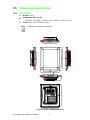
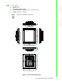
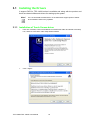
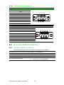
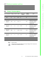
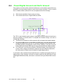
1
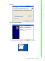
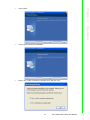
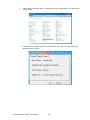
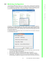
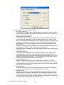
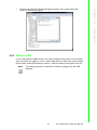
User Manual TPC-1582H/TPC-1782H Intel 4th Generation Core i Computer Copyright The documentation and the software included with this product are copyrighted 2014 by Advantech Co., Ltd. All rights are reserved. Advantech Co., Ltd. reserves the right to make improvements in the products described in this manual at any time without notice. No part of this manual may be reproduced, copied, translated or transmitted in any form or by any means without the prior written permission of Advantech Co., Ltd. Information provided in this manual is intended to be accurate and reliable. However, Advantech Co., Ltd. assumes no responsibility for its use, nor for any infringements of the rights of third parties, which may result from its use. Acknowledgements Intel and Pentium are trademarks of Intel Corporation. Microsoft Windows and MS-DOS are registered trademarks of Microsoft Corp. All other product names or trademarks are properties of their respective owners. This Manual Covers the Following Models: TPC-1582H TPC-1782H Part No. 2003158200 Edition 1 Printed in Taiwan January 2014 TPC-1582H/TPC-1782H User Manual ii Product Warranty (2 years) Advantech warrants to you, the original purchaser, that each of its products will be free from defects in materials and workmanship for two years from the date of purchase. This warranty does not apply to any products which have been repaired or altered by persons other than repair personnel authorized by Advantech, or which have been subject to misuse, abuse, accident or improper installation. Advantech assumes no liability under the terms of this warranty as a consequence of such events. Because of Advantech’s high quality-control standards and rigorous testing, most of our customers never need to use our repair service. If an Advantech product is defective, it will be repaired or replaced at no charge during the warranty period. For outof-warranty repairs, you will be billed according to the cost of replacement materials, service time and freight. Please consult your dealer for more details. If you think you have a defective product, follow these steps: 1. Collect all the information about the problem encountered. (For example, CPU speed, Advantech products used, other hardware and software used, etc.) Note anything abnormal and list any onscreen messages you get when the problem occurs. 2. Call your dealer and describe the problem. Please have your manual, product, and any helpful information readily available. 3. If your product is diagnosed as defective, obtain an RMA (return merchandize authorization) number from your dealer. This allows us to process your return more quickly. 4. Carefully pack the defective product, a fully-completed Repair and Replacement Order Card and a photocopy proof of purchase date (such as your sales receipt) in a shippable container. A product returned without proof of the purchase date is not eligible for warranty service. 5. Write the RMA number visibly on the outside of the package and ship it prepaid to your dealer. iii TPC-1582H/TPC-1782H User Manual Declaration of Conformity CE This product has passed the CE test for environmental specifications when shielded cables are used for external wiring. We recommend the use of shielded cables. This kind of cable is available from Advantech. Please contact your local supplier for ordering information. FCC Class A Note: This equipment has been tested and found to comply with the limits for a Class A digital device, pursuant to part 15 of the FCC Rules. These limits are designed to provide reasonable protection against harmful interference when the equipment is operated in a commercial environment. This equipment generates, uses, and can radiate radio frequency energy and, if not installed and used in accordance with the instruction manual, may cause harmful interference to radio communications. Operation of this equipment in a residential area is likely to cause harmful interference in which case the user will be required to correct the interference at his own expense. Technical Support and Assistance 1. 2. 3. Visit the Advantech web site at http://support.advantech.com where you can find the latest information about the product. Contact your distributor, sales representative, or Advantech's customer service center for technical support if you need additional assistance. Please have the following information ready before you call: – Product name and serial number – Description of your peripheral attachments – Description of your software (operating system, version, application software, etc.) – A complete description of the problem – The exact wording of any error messages This product is intended to be supplied by a listed power supply complying with UL60950-1. TPC-1582H/TPC-1782H User Manual iv Safety Instructions 1. 2. 3. 4. 5. 6. 7. 8. 9. 10. 11. 12. 13. 14. 15. 16. Read these safety instructions carefully. Keep this User Manual for later reference. Disconnect this equipment from any AC outlet before cleaning. Use a damp cloth. Do not use liquid or spray detergents for cleaning. For plug-in equipment, the power outlet socket must be located near the equipment and must be easily accessible. Keep this equipment away from humidity. Put this equipment on a reliable surface during installation. Dropping it or letting it fall may cause damage. The openings on the enclosure are for air convection. Protect the equipment from overheating. DO NOT COVER THE OPENINGS. Make sure the voltage of the power source is correct before connecting the equipment to the power outlet. Position the power cord so that people cannot step on it. Do not place anything over the power cord. All cautions and warnings on the equipment should be noted. If the equipment is not used for a long time, disconnect it from the power source to avoid damage by transient overvoltage. Never pour any liquid into an opening. This may cause fire or electrical shock. Never open the equipment. For safety reasons, the equipment should be opened only by qualified service personnel. If one of the following situations arises, get the equipment checked by service personnel: The power cord or plug is damaged. Liquid has penetrated into the equipment. The equipment has been exposed to moisture. The equipment does not work well, or you cannot get it to work according to the user's manual. The equipment has been dropped and damaged. The equipment has obvious signs of breakage. DO NOT LEAVE THIS EQUIPMENT IN AN ENVIRONMENT WHERE THE STORAGE TEMPERATURE MAY GO BELOW -20° C (-4° F) OR ABOVE 60° C (140° F). THIS COULD DAMAGE THE EQUIPMENT. THE EQUIPMENT SHOULD BE IN A CONTROLLED ENVIRONMENT. CAUTION: DANGER OF EXPLOSION IF BATTERY IS INCORRECTLY REPLACED. REPLACE ONLY WITH THE SAME OR EQUIVALENT TYPE RECOMMENDED BY THE MANUFACTURER, DISCARD USED BATTERIES ACCORDING TO THE MANUFACTURER'S INSTRUCTIONS. ATTENTION: Danger d'explosion si la batterie est mal REMPLACE. REMPLACER UNIQUEMENT PAR LE MEME TYPE OU EQUIVALENT RECOMMANDÉ PAR LE FABRICANT, jeter les piles usagées SELON LES INSTRUCTIONS DU FABRICANT. The sound pressure level at the operator's position according to IEC 704-1:1982 is no more than 70 dB (A). DISCLAIMER: This set of instructions is given according to IEC 704-1. Advantech disclaims all responsibility for the accuracy of any statements contained herein. v TPC-1582H/TPC-1782H User Manual Caution! Danger of explosion if battery is incorrectly replaced. Replace only with the same or equivalent type recommended by the manufacturer. Dispose of used batteries according to the manufacturer's instructions. Attention! Danger d'explosion si la pile est remplacée de façon incorrecte. Remplacez seulement avec le même type ou équivalent recommandé par le fabricant. Dispose des piles usagées selon les instructions du fabricant. TPC-1582H/TPC-1782H User Manual vi Contents Chapter 1 Overview...............................................1 1.1 1.2 1.3 Introduction ............................................................................................... 2 Packing List............................................................................................... 2 Specifications ............................................................................................ 3 1.3.1 General ......................................................................................... 3 1.3.2 System Hardware ......................................................................... 3 1.3.3 LCD Display .................................................................................. 4 1.3.4 Touchscreen ................................................................................. 4 1.3.5 Environment.................................................................................. 4 Interface .................................................................................................... 5 Figure 1.1 TPC-1582H/1782H - I/O Port Arrangement................ 5 Dimensions and Cutout............................................................................ 6 1.5.1 TPC-1582H ................................................................................... 6 Figure 1.2 TPC-1582H Dimensions............................................. 6 1.5.2 TPC-1782H ................................................................................... 7 Figure 1.3 TPC-1782H Dimensions............................................. 7 1.4 1.5 Chapter Chapter 2 Installation............................................9 2.1 2.2 2.3 2.4 Transport and Unpacking........................................................................ 10 Panel Mounting ....................................................................................... 10 Cabinet Installation and Earth Grounding setup ..................................... 11 Switching the Panel PC on and off.......................................................... 13 3 Operation............................................15 3.1 Installing the Drivers................................................................................ 16 3.1.1 Installation of Touch Screen driver ............................................. 16 3.1.2 Installation of Watchdog driver.................................................... 18 Touch Screen configuration .................................................................... 21 3.2.1 Device ......................................................................................... 22 3.2.2 Multiple Monitors......................................................................... 27 Watchdog Configuration.......................................................................... 29 Wake up from Suspend Mode................................................................. 31 3.4.1 Wake-on-LAN ............................................................................. 32 3.4.2 Wake-on-Touch Screen .............................................................. 34 3.4.3 Wake-on-USB ............................................................................. 35 3.2 3.3 3.4 Chapter 4 Technical Specifications...................37 4.1 Technical Specifications.......................................................................... 38 4.1.1 Electromagnetic compatibility .................................................... 38 4.1.2 Graphics...................................................................................... 38 4.1.3 Interfaces .................................................................................... 39 4.1.4 COM Port Pin Definition............................................................. 40 Table 4.1: RS-232 Standard Serial Port Pin Assignments ........ 40 Table 4.2: RS-232/422/485 Serial Port Pin Assignments.......... 40 Environmental Conditions ....................................................................... 40 4.2.1 Climatic ambient conditions ........................................................ 40 4.2.2 Mechanical ambient conditions................................................... 41 Power Consumption................................................................................ 41 Power/Digital Ground and Earth Ground ............................................... 42 4.2 4.3 4.4 vii TPC-1582H/TPC-1782H User Manual Appendix A A.1 Main Board Connector and Switch Settings43 Serial Port Settings ................................................................................. 44 TPC-1582H/TPC-1782H User Manual viii Chapter 1 Overview 1 1.1 Introduction The TPC-1582H/1782H computer with 15"/17” XGA/SXGA LCD displays, low power embedded Intel 4th Generation Core i3 1.7GHz processor and 4GB DDR3 SDRAM provides the high computing performance in a compact fanless system. To enhance its durability, the TPC-1582H/1782H are designed with IP65 compliant front protection, die-cast Al Alloy front bezel and 5-wire resistive touch. It also includes PCIe slot and Mini-pcie slots to extend the functionality and meet a variety of automation applications needs. Through the Mini-PCIe slot, Advantech iDoor technology can provide more I/O connectors, Isolated Digital IO, the Fieldbus Protocol, 3G/GPS/GPRS/WiFi Communication and MRAM. A 2nd monitor and speaker can be attached via the integrated HDMI and Audio port. The pre-loaded SusiAccess is a smart, unique and ready-to-use remote device management software for you to centralize monitoring and managing of remote embedded devices in real-time. You can focus more on your own applications and let SusiAccess do the rest - configure systems, monitor device health, and recover from any system failures. It’s cloud based and provides on-demand software services so you can easily download and upgrade applications when you need. Feature Highlights Industrial 15"/17” XGA TFT LCD with 50K Lifetime LED Backlight Intel 4th Generation Core i3 1.7GHz with 4GB DDR3L SDRAM Compact Fanless Embedded System with Al Alloy Front Bezel IP65 compliant Front Protection & Panel Mounting More Durable 5-wire Resistive Touch Screen PCIe and Mini PCIe Expansion Support Diverse system IO and Isolated Digital IO by iDoor Technology Supports Fieldbus Protocol by iDoor Technology 3G/GPS/GPRS/WiFi Communication by iDoor Technology Supports MRAM by iDoor Technology Chassis Grounding Protection HDMI and Audio Multimedia Support Supports Advantech WebAccess NMS (Network Management Software) with built-in Advantech SNMP Subagent. Supports Advantech SusiAccess Remote Device Management Software 1.2 Packing List 10 x Panel Mount Clamps 10 x Panel Mount Screws 1 x 3 Pin Power Connector 1 x Power Indication Sticker 1 x Wire for Chassis Ground 1 x TPC Driver DVD 1 x Registration and Warranty Card 1 x Simplified Chinese Manual TPC-1582H/TPC-1782H User Manual 2 1.3.1 General Watchdog Timer: 1 ~ 255 sec (system) Weight (Net): TPC-1582H: 5.5 kg (12.13 lbs) TPC-1782H: 6 kg (13.23 lbs) 1.3.2 System Hardware CPU: TPC-1582H: Intel 4th Generation Core i3-4010U 1.7GHz TPC-1782H: Intel 4th Generation Core i3-4010U 1.7GHz Chipset: Lynx Point-LP Memory: 4GB DDR3L SO-DIMM SDRAM LAN: 10/100/1000Base-T x 2 Expansion Slots: Half-size PCI-E or full-size Mini PCI-E Storage: CFast slot x 1 2.5" SATA SSD slot x 1 Supports 1 x mSATA via Mini PCIe slot I/O: RS-232 x 1, RS-232/422/485 x 1 USB 3.0 x 2, HDMI 1.4 x 1 Audio Line out x 1, USB 2.0 x 1 (optional) Audio MIC x 1 (optional) 3 TPC-1582H/TPC-1782H User Manual Overview BIOS: AMI UEFI Certification: BSMI, CCC, CE, FCC Class A, UL Cooling System: Fanless design Dimensions TPC-1582H: 383 x 307 x 78.5 mm (15.08" x 12.09" x 3.09") TPC-1782H: 414 x 347.5 x 84 mm (16.3" x 13.68" x 3.31") Enclosure Front bezel: Die-cast Aluminum alloy Back housing: PC/ABS Resin Mounting: Desktop, Wall or Panel Mount OS Support Microsoft® Windows WES7 32bit/64bit /WE8S 64bit / Windows 7 32bit/64bit / Windows Embedded 8 Industry Pro; Linux Kernel 3.x Power Consumption: 21 W (typical) Power Input: 24VDC +/- 20% Chapter 1 1.3 Specifications 1.3.3 LCD Display TPC-1582H Display Type: XGA TFT LED LCD Display Size: 15" Max. Resolution: 1024 x 768 Max. Colors: 16.2 M Luminance cd/m2: 400 Viewing Angle (H/V°): 160/140 Backlight Life: 50,000 hrs Contrast Ratio: 700:1 TPC-1782H Display Type: SXGA TFT LED LCD Display Size: 17" Max. Resolution: 1280 x 1024 Max. Colors: 16.7 M Luminance cd/m2: 350 Viewing Angle (H/V°): 160/140 Backlight Life: 50,000 hrs Contrast Ratio: 800:1 1.3.4 Touchscreen Lifespan: 36 million touches at single point Light Transmission: Above 75% Resolution: Linearity Type: 5-wire, analog resistive 1.3.5 Environment Humidity: 10 ~ 95% RH @ 40°C, non-condensing Ingress Protection: Front panel: IP65 compliant design Operating Temperature: 0 ~ 55°C (32 ~ 131°F) Storage Temperature: -20 ~ 60°C (-4 ~ 140°F) Vibration Protection: With HDD: 1 Grms (5 ~ 500 Hz) (Operating, random vibration) TPC-1582H/TPC-1782H User Manual 4 The arrangement of the I/O ports is shown in Figure 1.1. Chapter 1 1.4 Interface Overview Figure 1.1 TPC-1582H/1782H - I/O Port Arrangement 5 TPC-1582H/TPC-1782H User Manual 1.5 Dimensions and Cutout 1.5.1 TPC-1582H Weight: 5.5kg Dimensions (W x H x D): – 383.0±0.7 x 307.0±0.7 x 78.5±1.5 mm (15.08" x 12.09" x 3.09") Cutout: 374.5 ±0.7x 298.5±0.7 mm Note! Antenna not included in the pack. Figure 1.2 TPC-1582H Dimensions TPC-1582H/TPC-1782H User Manual 6 Weight: 6kg Dimensions (W x H x D): – 414±1 x 347.5±1 x 84±1.5 (16.3" x 13.68" x 3.31") Cutout: 400.8±1 x 334.3 ±1 Note! Antenna not included in the pack. Chapter 1 1.5.2 TPC-1782H Overview Figure 1.3 TPC-1782H Dimensions 7 TPC-1582H/TPC-1782H User Manual TPC-1582H/TPC-1782H User Manual 8 Chapter 2 Installation 2 2.1 Transport and Unpacking When accepting a delivery, please check the packaging for visible transport damage and check the delivery for completeness by comparing it with your order. If you notice any shipping damage or inconsistencies between the contents and your order, please inform the responsible delivery service immediately. During transport, the TPC should be protected from excessive mechanical stress. If the TPC is transported or stored without packaging, shocks, vibrations, pressure and moisture may impact the unprotected unit. A damaged packaging indicates that ambient conditions have already had a massive impact on the device. Therefore, please use the original packaging during transportation and storage. If the TPC is transported in cold weather or is exposed to extreme variations in temperature, make sure that moisture (condensation) does not build up on or inside the HMI device. Moisture can result in short-circuits in electrical circuits and damage the device. To avoid that, please store the TPC in a dry place and bring the TPC to room temperature before starting it up. If condensation occurs, a delay time of approximately 12 hours must be allowed to make sure the TPC is completely dry before the TPC is switched on. 2.2 Panel Mounting 1. Position the TPC against the panel. 2. Insert the holding clip into the side of the TPC. TPC-1582H/TPC-1782H User Manual 10 Secure the clip to the panel using the included screws Please follow the following steps to setup TPC-1x82H series, and please pay attention that Ground pin of TPC-1x82H series should be connected to earth ground. Under this circumstance, TPC-1x82H series could have the best performance such as EMI immunity, ESD immunity, Surge immunity and also system isolation. If TPC-1x82H series is embedded in the cabinet, TPC-1x82H’s ground, cabinet’s ground and earth ground should all be connected together. 1. Embed TPC-1x82H series into the cabinet. Step A: Connect the cabinet to earth ground. Step B: Embed null TPC-1x82H series into the cabinet without any I/O cable and power. 11 TPC-1582H/TPC-1782H User Manual Installation 2.3 Cabinet Installation and Earth Grounding setup Chapter 2 3. 2. System wiring Step A: Connect the cabinet to earth ground. Step B: Ensure that all cabinet has been grounded together. Step C: Connect the ground of the power supply to the cabinet. Step D: Connect the ground pin of TPC-1x82H series to the cabinet. Step E: Connect the I/O to the controller if needed. Step F: Connect the V+ and V- of power supply to TPC-1x82H series. While completing step A to F step by step, you can supply power to TPC-1x82H series now. Note! Make sure all wires follow the installation guidelines or it may cause issues. Note! If you install a USB device or Mini PCIe card on the TPC-1x82H, please double check the voltage between V- and earth ground, if the voltage is not almost equal with each other, we suggest to short V- and earth ground with wiring. TPC-1582H/TPC-1782H User Manual 12 13 TPC-1582H/TPC-1782H User Manual Installation Before switching TPC on, please make sure the protective conductor has been well connected. The protective conductor discharges dangerous currents, triggering a surge protection switch. The protective conductor also discharges any interference transmitted from external power supply cables, signal cables or cables to the I/O devices. See Chapter 1.4 for protective conductor location and Chapter 2.3 for cabinet installation and earth grounding setup. The Panel PC does not have its own mains power switch. As soon as the power supply is switched on the Panel PC is activated. It is suggested to turn OFF system power as you plug in or pull out the memory card, even though the CompactFlash memory is hot swappable. Connect the power connector to the 24 VDC power lines. The power lines can either be of some power adapter or in-house power source. Chapter 2 2.4 Switching the Panel PC on and off TPC-1582H/TPC-1782H User Manual 14 Chapter 3 Operation 3 3.1 Installing the Drivers A support DVD for TPC-1x82H series is available and along with the product and there are related utilities and drivers for starting up the system. Note! You can download the latest driver on the Advantech support portal of Advantech’s website if there is any updated. 3.1.1 Installation of Touch Screen driver 1. Enter into TS folder, enter into PenMount Universal Driver folder and double click setup icon, and then click “Next” under setup wizard window. 2. Click “I Agree” TPC-1582H/TPC-1782H User Manual 16 Click “Install” 4. Click “Finish” to finish the installation 5. After installing Touch Screen driver, a “PenMount Monitor” icon will show on your notification area. Chapter 3 3. Operation 17 TPC-1582H/TPC-1782H User Manual 3.1.2 Installation of Watchdog driver 1. Enter into Watchdog folder, double click AdvWDT icon, and then click “Next” under InstallShield Wizard window 2. Select “Advantech [EC] WDT” and click “Next” TPC-1582H/TPC-1782H User Manual 18 Click “Install” 4. Click “Finish” to finish the installation 5. Select “Yes, I want to restart my computer now” and click “OK” Chapter 3 3. Operation 19 TPC-1582H/TPC-1782H User Manual 6. After installing Watchdog driver, a “Watchdog Service Configuration” icon will show in control panel 7. Double click the “Watchdog Service Configuration” icon, and you can configure the Watchdog timer function. TPC-1582H/TPC-1782H User Manual 20 PenMount Monitor icon (PM) appears in the notification area of Windows system when you turn on PenMount Monitor in PenMount utility. Chapter 3 3.2 Touch Screen configuration Operation 1. Control Panel Open PenMount Control Panel 2. Beep Setting Beep function for each device. 3. Right Button When you select this function, a mouse icon appears in the right-bottom of the screen. Click this icon to switch between Right and Left Button functions. 4. Exit Exits the PenMount Monitor function. 21 TPC-1582H/TPC-1782H User Manual Right-click on the PenMount Monitor icon in the notification area and select Control Panel from the menu. You will see Device, Multiple Monitors, Tools and About tabs which will introduce their function in this section. 3.2.1 Device You will see the icon of PenMount 6000 USB under Device tab. In Device tab, you can see the devices detected on your system. Select a device and press the Configure button to configure it. TPC-1582H/TPC-1782H User Manual 22 Chapter 3 Then, you will see some tabs such as Calibrate, Setting, Edge Compensation, and About of the device you selected. Operation 3.2.1.1 Calibrate This function offers two ways to calibrate your touchscreen. 'Standard Calibration' adjusts most touchscreens while 'Advanced Calibration' adjusts aging touchscreens. You can select either or both method to calibrate your touchscreens. 23 TPC-1582H/TPC-1782H User Manual 1. Standard Calibration: Click this button and arrows appear pointing to red squares. Use your finger or stylus to touch the red squares in sequence. After the fifth red point calibration is complete. To skip, press 'ESC'. Note! 2. Advanced Calibration: Advanced Calibration uses 9, 16 or 25 points to effectively calibrate touch panel linearity of aged touchscreens. Click this button and touch the red squares in sequence with a stylus. To skip, press 'ESC'. Note! 3. 4. The older the touchscreen gets, the more Advanced Mode calibration points you need for an accurate calibration. Use a stylus for Advanced Calibration for greater accuracy. It is recommended that you use a stylus for Advanced Calibration for greater accuracy. Plot Calibration Data: Check this function to have touch panel linearity comparison graph appear when you finish Advanced Calibration. The black lines reflect the ideal linearity assumed by PenMount's application program while the blue lines show the approximate linearity calculated by PenMount's application program as the result of user's execution of Advance Calibration. Turn off EEPROM storage: This function disables the write-in of calibration data in the controller. This function is enabled by default. TPC-1582H/TPC-1782H User Manual 24 Chapter 3 3.2.1.2 Setting Operation 1. Operation Mode: This mode enables and disables mouse's ability of dragging on-screen icons-useful for configuring POS terminals. – Pen Input Emulation: Select this mode and mouse will emulate Windows Vista pen input device operation, by which no mouse event will be sent until the touch is dragged out of range or released from the screen. – Click on Touch: Select this mode and mouse only provides a click function, and dragging is disabled. – Mouse Emulation: Select this mode and mouse functions as normal and allows dragging of icons. – Click on Release: Select this mode and mouse only provides a click function when the touch is released. 2. Beep Sound: Enable Beep Sound: Turns beep function on or off. Beep on Pen Down: Beep occurs when pen comes down. Beep on Pen Up: Beep occurs when pen is lifted up. Beep on Both: Beep occurs when comes down and is lifted up. Beep Frequency: Modify sound frequency. Beep Duration: Modify sound duration. Kind of Sound: TPC-1x82H series only support Buzzer beep. 3. Cursor Stabilizer: Enable the function support to prevent cursor shake. 4. Use press and hold as right click: You can set the time out and area for you need 25 TPC-1582H/TPC-1782H User Manual 3.2.1.3 Edge Compensation Edge compensation is used to optimize the cursor accuracy on the edge, which is for advanced calibration. You can adjust the settings from 0 to 30 for accommodating the difference of each touch panel. 3.2.1.4 About This tab shows the information about the PenMount controller and driver version TPC-1582H/TPC-1782H User Manual 26 Chapter 3 3.2.2 Multiple Monitors Operation Multiple Monitors supports two to six touchscreen displays for one system. However TPC-1x82H series only provides one touchscreen display so this function is not workable on TPC-1x82H series. 3.2.2.1 Tools In Tools tab, there are Draw, Right Button Icon, functions. They will be introduced in this section. 3.2.2.2 Draw Draw function is used to test or demonstrate the PenMount touchscreen operation. 27 TPC-1582H/TPC-1782H User Manual Click Draw to start. Touch the screen with your finger or a stylus and the drawing screen registers touch activity such left, right, up, down, pen up, and pen down. And click Menu button for more functions. 1. Show Grid: Show grid on the entire monitor. This is for linearity test. 2. Show Pen Location: Show the locations where pen comes down and lifted up on the monitor. Clear Screen: Clear drawing Exit: Quit draw function 3. 4. 3.2.2.3 Right Button Icon Right Button function simulates the right button function of a mouse. Click the right button and you can only touch the screen once and the driver changes the touch definition to the left button. When you select this function, a mouse icon appears in the right-bottom of the screen. Click this icon to switch between Right and Left Button functions. TPC-1582H/TPC-1782H User Manual 28 The Watchdog WDM Driver allows you to easily perform versatile WDT operations through properties, methods and events in programs developed with Microsoft Visual C++ and Microsoft Visual Basic. After you complete to install the Watchdog driver, you can access Watchdog Service Configuration utility in control panel. Chapter 3 3.3 Watchdog Configuration Operation Furthermore, if you need more detail information, please refer to C:\Program Files\Advantech\Watchdog for Watchdog WDM Driver User's Manual which introduce Application Programming Interface (API) including calling procedure of operating Watchdog device, Control Panel Program (CPL) of the driver, and step-by-step instructions for building applications with the Watchdog WDM Driver. The Watchdog Service Configuration utility can be accessed in the control panel. Double the icon and a dialog will pop up. In the General tab, there are four static labels: 1. 2. 3. 4. Service Name: display the name of the Advantech Watchdog service in the Service Control Manager (SCM) database. Watchdog Type: display the Watchdog chipset type. Such as EC. Running Status: display the Watchdog current status: enabled or disabled. Elapsed time: The elapsed time from the time that the Watchdog is enabled. If the Watchdog is disabled the elapsed time will be 00 hour 00 minute 00 second. 29 TPC-1582H/TPC-1782H User Manual In the Setting tab, there are the following items: 1. Timer Span combo box: 2. 3. 4. 5. 6. You can select one timer span for the Watchdog and apply the changes when the Watchdog is disabled, there are 6 timer span arranges from 15 seconds to 4 minutes 15 seconds available. Watch Mode radio box group: There are two watch modes, system watch mode and application watch mode. If you checked the “Application” mode and apply settings by the “Apply” button, then if you enable the Watchdog later, there will pop up a piece of warning message which is shown below to notify you to strobe the Watchdog manually by click the “Strobe” button, otherwise the machine will reboot depending on the time you set. Definition: System mode: Watchdog timer is running in Windows background. If the hardware is hung up, it will reboot system automatically. Application mode: Watchdog timer will be enabled when you call the APIs within your application. Log Event check box: If this check box is checked and the settings is applied by the “Apply” button, then the “Enabled”, “Disable”, “Reboot” operation of the Watchdog will be logged into the system event base, otherwise the three operation will be not be logged into the system event base. For more detail about log function, please refer to the Watchdog WDM Driver User's Manual. Enable/Disable button: Enable or disable the Watchdog. If the Watchdog is enabled, you can not change the watch mode and the timer span of the Watchdog, so these related controls become grayed. These controls resume to their normal status when the Watchdog becomes disabled. Strobe button: Strobe the Watchdog. This button become available only when the Watchdog runs in application-watch mode and the Watchdog is enabled. Reboot button: Reboot the machine by no strobe the Watchdog hardware. This button is not available when the Watchdog is disabled. If the Watchdog is enabled and you click this “Reboot” button then all the three buttons: “Enable/Disable”, “Strobe” and “Reboot” becomes grayed, no operations can cancel the rebooting machine operation but stop the Advantech Watchdog service. TPC-1582H/TPC-1782H User Manual 30 Chapter 3 Operation In the About tab, there shows some copyright information of the Advantech Watchdog service. 3.4 Wake up from Suspend Mode TPC-1x82H series has three wake-up modes which can let you do versatile setting such as remote control. You can wake up the system on USB, LAN and touch screen. The following table shows each wake-up mode in detail. Wake up from TPC-1582H LAN1 LAN2 Touch screen USB Note! S3 V V V V TPC-1782H S5 V V - - S3 V V V V S5 V V V - S3: Sleep state where all system context is lost except system memory. OS context is maintained within the memory and is not reloaded at startup. S5: This sleep state looks very much like S4 with the exception of the fact that the OS context is not stored off. The OS must be reloaded. 31 TPC-1582H/TPC-1782H User Manual 3.4.1 Wake-on-LAN Wake-on-LAN function of TPC-1x82H series is supported in both ACPI (Advanced Configuration Power management Interface) and APM (Advanced Power Management) environments and it can wake the system from S3 and S5. The Wake-on-LAN API should be installed on your host terminal while TPC-1x82H series which will be awaked is regarded as a client device. Also, you need to enable the Wake-on-LAN function on TPC-1x82H series. Please follow the following steps. 1. Enter Network Connections setting, right-click on the Local Area Connection icon, and select “Properties.” 2. In the Networking tab, select “Configure” button. TPC-1582H/TPC-1782H User Manual 32 In Power Management tab, check “Wake on LAN items” to enable the Wake-onLAN function. Chapter 3 3. Operation 33 TPC-1582H/TPC-1782H User Manual 3.4.2 Wake-on-Touch Screen If you need wake-on-touch screen function, you need to enable the function in Device Manager under Windows. Touch screen can wake up the system from S3. 1. Enter into Device Manager, then you can find touch device is belong to "Microsoft Input Configuration Device" or “Mice and other pointing devices”. TPC-1582H/TPC-1782H User Manual 34 Double click and select Power Management page, then enable "Allow this device to wake the computer". Chapter 3 2. Operation 3.4.3 Wake-on-USB If you need wake-on-USB function, you need to enable the function in Device Manager and follow the steps in 3.4.2 to select USB device in Mice and other pointing devices then enable USB wake up function.. USB can wake up the system from S3. Note! The setting depends on what kind of device is plugged into the USB interface. 35 TPC-1582H/TPC-1782H User Manual TPC-1582H/TPC-1782H User Manual 36 Chapter 4 Technical Specifications 4 4.1 Technical Specifications 4.1.1 Electromagnetic compatibility EN 61000-6-4; CISPR 22:2004 Class A; FCC Class A Emission standard Immunity with regard to conducted ± 2 kV in accordance with IEC 61000-4-4; interference on the supply lines ± 0.5 kV in accordance with IEC 61000-4-5; DC Mode Immunity to electrostatic discharge ± 6 KV contact discharge at the front in accordance with IEC 61000-4-2 ± 4 kV, housing contact discharge at the back in accordance with IEC 61000-4-2 ± 8 kV air discharge in accordance with IEC 61000-4-2 Immunity to RF interference 10 V/m, 80 to 1000 MHz 80% AM according to IEC 61000-4-3 10 V/m, 1.4 to 2 GHz 1 V/m, 2 to 2.7 GHz 10 V, 9 kHz to 80 MHz according to IEC 61000-4-6 4.1.2 Graphics Display, resolution Touch controller 15" screen diagonal with backlighting, resolution 1024 x 768 pixels, XGA 17" screen diagonal with backlighting, resolution 1280 x 1024 pixels, SXGA PenMount PM6200D Combo 5-wire Control Board Touch screen analog resistive Touch force with test pen; 2 mm diameter: 5 N Backlighting (MTBF) LED Half brightness life time, min. 50000 h at 50 °C, 50% brightness typical TPC-1582H/TPC-1782H User Manual 38 TPC-1582H TPC-1782H RS232, max. 115 kbps, sub-D connector, 9-pin RS-232/422/485, sub-D con- RS-232/422/485, sub-D nector, 9-pin connector, 9-pin RS-232: 50 ~ 115.2 kbps RS-232: 50 ~ 115.2 kbps RS-422/485: 50 ~ 921.6 kbps RS-422/485: 50~115.2Kbps (Max.) COM 1 COM 2 256 Byte RX FIFOs 128Byte RX FIFOs Note: You can select COM2 model through BIOS setting and RS485 support auto flow function USB LAN interface A, RJ45 1 LAN interface B, RJ45 1 Keyboard, mouse 2 x USB 3.0 support super speed, up to 5Gbps Intel I218LM Gigabit Ethernet supports 10/100/1000 bps Intel I210 Gigabit Ethernet supports 10/100/1000 bps and teaing function and jumbo frame. Connection via USB interface 1 For unique labeling, the LAN interfaces are numbered on the housing. The numbering by the operating system can differ. 39 TPC-1582H/TPC-1782H User Manual Technical Specifications FIFOs Chapter 4 4.1.3 Interfaces 4.1.4 COM Port Pin Definition Table 4.1: RS-232 Standard Serial Port Pin Assignments Pin RS-232 Signal Name 1 DCD 2 RxD 3 TxD 4 DTR 5 GND 6 DSR 7 RTS 8 CTS 9 RI 1 2 3 4 5 6 7 8 9 Table 4.2: RS-232/422/485 Serial Port Pin Assignments Pin RS-232 RS-422 RS-485 1 DCD Tx- DATA- 2 RxD Tx+ DATA+ 3 TxD Rx+ 4 DTR Rx- 5 GND GND 6 DSR 7 RTS 8 CTS 9 RI 1 2 3 4 5 GND 6 7 8 9 4.2 Environmental Conditions 4.2.1 Climatic ambient conditions Permitted mounting positions see section “Preparing for installation” Temperature, tested in accordance with IEC 60068-2-1, IEC 60068-2-2 Temperature gradient in operation Max. 10 °C/h, no condensation Maximum ambient temperature in operation 0~+55°C Permissible relative humidity to 95%, no condensation Operation Storage/transport TPC-1582H/TPC-1782H User Manual 5 … 85% at 30 °C, no condensation 5 … 95% at 25 °C, no condensation 40 Chapter 4 4.2.2 Mechanical ambient conditions Vibration, tested according to DIN IEC 60068-2-6 Non-operation, 5~500 Hz, 2G Shock resistance, tested in accordance with IEC 60068-2-27 Operation, 10G, 11ms 4.3 Power Consumption Watt Recommended Power amount of Demand current Note 1 Power on 24 0.7 16.8 0.875 21 - 2 Boot up to Win7 24 1.2 28.8 1.5 36 - 3 Idle 24 0.6 14.4 0.75 18 - 38.4 CPU 50%, RAM 50%, Disk 50%, Vedio 50%, Sound 50%, Network 50%, 2D 50%, 3D 300*200 50% 39 CPU 50%, RAM 50%, Disk 50%, Vedio 50%, Sound 50%, Network 50%, 2D 50%, 3D 300*200 50% 39.6 CPU 50%, RAM 50%, Disk 50%, Vedio 50%, Sound 50%, Network 50%, 2D 50%, 3D 300*200 50% 4 5 6 Run PassMark 6.0 Run PassMark 6.0 Run PassMark 6.0 19.2 24 28.8 1.6 1.3 1.1 30.72 31.2 31.68 2 1.625 1.375 7 Run PassMark 6.0 24 1.7 40.8 2.125 51 CPU 50%, RAM 50%, Disk 50%, Vedio 50%, Sound 50%, Network 50%, 2D 50%, 3D 800*600 50% 8 Sleep 24 0.048 1.152 0.06 1.44 - 9 Hibernate 24 0.045 1.08 0.05625 1.35 10 Shutdown 24 0.04 0.96 0.05 1.2 . Note! Inrush current The inrush current of the device at an input voltage of 24 V amounts to at least 8 A for a period of 30 ms. 41 TPC-1582H/TPC-1782H User Manual Technical Specifications No. Test Criteria Voltage Current 4.4 Power/Digital Ground and Earth Ground The purpose is to block all the external interference on the chassis, and prevent any possibility of bad grounding design to cause electric shock of people. This is so called level 1 isolation which consumer PC do not implement this kind of design. TPC Chassis and Earth (Power pin3) are short, TPC Chassis and Power / Digital GND are OPEN The TPC is and industrial grade product, designed to prevent external interference and the possibility of electric shock. To complete the isolation design, we need to consider the following: The Ethernet is isolated, a LAN connection will not impact the isolation design. For general USB devices, to solve EMI and ESD issues, they are designed as a chassis and digital short. But the TPC prevents damage to USB devices, ESD and EMI solutions are designed to use the Power GND as a vent path to ensure Power GND and Chassis GND will not have potential difference abnormalities. For COM ports, since there are different COM port designs, long distance connection cause voltage level difference between the two COM port chassis.So the shell ground of cable must be isolated to signal digital ground In real cases, many customers may break the level 1 isolation by 3rd party Device or cable design, in this situation, we need to consider making all the GND short (Power GND/Digital GND/Earth GND), and ensure customers have good Earth GND connection. TPC-1582H/TPC-1782H User Manual 42 Appendix A A Main Board Connector and Switch Settings A.1 Serial Port Settings The TPC-1x82H series have 2 serial ports, COM1 supports RS-232 mode and COM2 supports RS-232/422/485 model. You can select COM2 as RS-232/422/485 mode under BIOS configuration. The default setting of COM2 is RS-232 mode. The connector location is shown in the following figure. To setup COM2 as RS422/485, enter the BIOS menu during boot up by pressing the DEL key, in the Advanced submenu, change COM2 Uart mode setting to RS422/485 as in the following picture. Caution! Don't change any settings unless you understand the consequences. TPC-1582H/TPC-1782H User Manual 44 45 TPC-1582H/TPC-1782H User Manual Appendix A Main Board Connector and Switch Settings In TPC-1582H, you will need to boot into OS to install COM driver and configure COM setting manually to COM1 and COM2 as following picture. TPC-1582H/TPC-1782H User Manual 46 Appendix A Main Board Connector and Switch Settings TPC-1582H/TPC-1782H User Manual 47 www.advantech.com Please verify specifications before quoting. This guide is intended for reference purposes only. All product specifications are subject to change without notice. No part of this publication may be reproduced in any form or by any means, electronic, photocopying, recording or otherwise, without prior written permission of the publisher. All brand and product names are trademarks or registered trademarks of their respective companies. © Advantech Co., Ltd. 2014