1
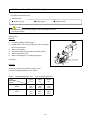
ASAHI AV Valves
Serial No.
H – A015 E – 1
Contents
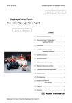
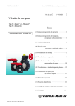
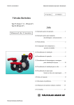
Diaphragm Valve Type 14
Pneumatic Model Type AV
User’s Manual
(1)
General operating instructions
1
(2)
General instructions for transportation,
unpacking and storage
1
(3) Name of parts
2
(4) Comparison between working
temperature and pressure
3
5)
Specifications of actuator
4
6)
Specifications of option
Specifications of solenoid valve
Specifications of limit switch
Specifications of pressure reducing valve
with filter
Specifications of speed controller
4
4
5
7)
Installation procedure
6
8)
Air piping procedure
7
9)
Support setting procedure
9
5
5
10) Connection of limit switch procedure
10
11) Connection of solenoid valve procedure
11
12) Operating procedure
Adjustment of opening / closing
speed procedure
12
13) Adjustment procedure for stopper
15
14) Disassembling method for replacing parts
16
15) Inspection items
18
16) Troubleshooting
18
17) Handling of residual and waste materials
19
18) Inquiries
20
- 0 -
13
(1) General operating instruction
○ Operate the valve within the range of the published working temperature and pressure.
(The valve can be damaged by operation beyond the maximum allowable range of temperature or pressure.)
○ To select a valve in appropriate materials, refer to “CHEMICAL RESISTANCE ON ASAHI AV VALVE”.
(Some chemicals give heavy damage to valve materials.)
○ Diaphragm part may become loose after long term storage or unused period, or by the change of temperature
during operation. Check it, and re-tighten the bolt between the actuator and the body diagonally, refer to the
torque value on page 16. (The valve may leak.)
○ Do not disassemble the actuator. (Injury may occur.)
○ The valve is not designed to bear any kind of external load. Never stand on or place anything heavy on the valve
at anytime.
○ When the valve is disposed of, contact waste disposal specialist. (The valve generates toxic gas.)
○ The valve should be installed at place where space for periodic inspection & maintenance is sufficient.
○ Do not store or install the valve near any heat source or hot surface.
○ Set valve support on the valve. (Refer to page 9)
○ Keep the valve away from places of direct sunlight, water and dust. Use cover to shield the valve.
(The valve will not operate properly.)
○ Do not use AV valves in a place where they may become submerged in water.
(Submergence will make AV valve fail.)
(2) General instructions for transportation, unpacking and storage
○ Keep the valve in its original packaging until needed for installation.
○ Avoid contact with any coal tar creosote, insecticides, vermicides or paint.
(The force of swelling may damage the valve.)
○ The valve is not designed to handle any kind of impact. Avoid throwing or dropping the valve.
○ Avoid scratching the valve with any sharp object.
- 1 -
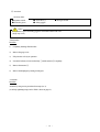
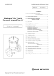
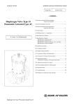
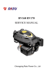
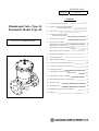
(3) Name of parts
Nominal size 65-100mm (2 1/2”-4”)
No.
1
◯
1a
◯
3
◯
4
◯
5
◯
11
◯
DESCRIPTION
Body
Nut
Diaphragm
Cushion
Cushion cover
Gauge cover
No.
18
◯
18a
19
◯
20
◯
24
◯
28
◯
DESCRIPTION
Bolt-nut(A)
Washer(A)
Spring-washer(A)
Stopper
Ensat (inset metal)
Actuator (double action)
- 2 -
No.
29
◯
30
◯
90
◯
99
◯
100
106
DESCRIPTION
Actuator (air to shut)
Actuator (air to open)
Stud bolt-nut
Valve sheet
Gasket(A)
Stand
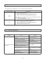
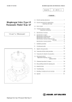
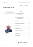
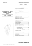
(4) Comparison between working temperature and pressure
Caution
Do not operate the valve beyond the range of working temperature and pressure.
(The valve can be damaged)
- 3 -
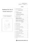
(5) Specifications of Actuator
Nominal size
Standard operating pressure
All type
MPa {kgf/cm2} [PSI]
Double action type
Air consumption
N/ per 1 open and close
Air to open type
(at 0.4MPa)
Air to close type
Air supply bore
All type
65mm(2 1/2”)
80mm(3”)
100mm(4”)
0.4{4.1}[58]
10.3
10.6
9.4
11.9
15.9
11.7
Rc 1/4
20.7
34.3
26.5
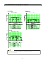
(6) Specifications of Option
(Specifications of Solenoid valve)
Actuation
Nom. size
Type sign
All type
65-100mm
(2 1/2”-4)
4N3S102K
-W□-G31193
Effective
Pipe bore cross section
area
Rc 1/4
10mm2
or more
4N3S102K-W□-G31193
AC ; 6VA
DC ; 5.5W
Additional function
○
○
Bypass valve built – in
Silencer with needle valve
attached
(to be used as speed controller)
Specification
AC100V 50/60Hz
AC110V 50/60Hz
AC200V 50/60Hz
AC220V 50/60Hz
DC24V
DC48V
DC100V
DC125V
* ( )is special order.
connection diagram Power
consumption
JIS sign
- 4 -
sign
1
(2)
3
(4)
5
(6)
(7)
(9)
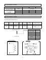
(Specifications of Limit switch)
Actuation
Nominal size
Type sign
Protection grade
Double actuation,
Single actuation type
65-100mm
(2 1/2”-4”)
1LS1-J
Equivalent to IP55
Limit switch rating Rate voltage (V)
resistive load (A)
AC125
AC250
DC125
DC250
connection diagram
Inductive load (A)
10
10
0.8
0.4
(At intermediate opening)
6
6
0.2
0.1
(Specification of pressure reducing valve with filter)
Actuation
All type
Nom. size
65mm(2 1/2”)
80mm(3”)
100mm(4”)
Type sign
Pipe
bore
Element
degree of
filtration
ARU2-02-8A-B
Rc 1/4
5μm
(Specification of speed controller)
JIS sign
Actuation
Nom. size
Type sign
Pipe bore
All type
65-100mm
(2 1/2”-4”)
SC7-08A
Rc 1/4
Actuation
All type
Effective cross section area mm2
(inch2)
Free flow
Control flow
11.0(0.017)
8.3(0.013)
JIS sign
Needle No. of
revolution
8turns
- 5 -
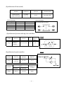
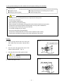
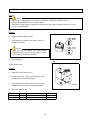
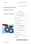
(7) Installation procedure
Necessary items
● Torque wrench
● Spanner wrench
● Bolt, Nut, Washer (For many flanges specification)
● AV gasket (When a non-AV gasket is used, a different tightening torque instruction should be followed.)
Procedure
1) Set the AV gasket between the flanges.
2) Insert washers and bolts from the pipe side, insert washers and nuts from the valve side, then
temporarily tighten them by hand.
Caution
The parallelism and axial misalignment of the flange surface should be below the values in the following
(A failure to observe them can cause destruction due to stress application to the pipe)
Unit : mm(inch)
Nom. Size
Axial
Misalignment
Parallelism
(a-b)
65, 80mm
(2 1/2”, 3”)
100mm
(4”)
1.0mm
(0.04”)
1.0mm
(0.04”)
0.8mm
(0.03”)
1.0mm
(0.04”)
(Axial misalignment)
(Parallelism)
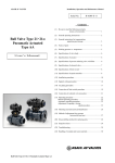
3) Using a torque wrench, tighten the bolts and nuts gradually to the specified torque in a diagonal manner.
(Refer to fig.1.)
Specified torque value Nom. Size
Torque value
Unit: N-m{kgf-cm}[lb-inch]
65 mm
80, 100 mm
(2 1/2”)
(3”, 4”)
22.5
30.0
{230}
{306}
[200]
[266]
Caution
Avoid excessive tightening. (The valve can be damaged.)
- 6 -
Fig. 1
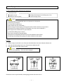
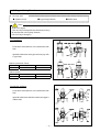
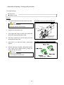
(8) Air Piping procedure
<1> For a standard type and an attached speed controller type
Necessary items
● Spanner wrench
● Steel pipe or tube for piping
● Seal tape (If seal tape isn’t used, leakage may occur)
● Joint for steel pipe or tube
Caution
Use compressed air as operating fluid. Don’t use oil pressure or water pressure.
(Actuator may be damaged.)
Use clean, filtered compressed air.
(If not, actuator may not work normally.)
When a steel pipe is used for piping, use the pipe the inside of which is treated to be rust preventive.
(The intrusion of rust into the actuator the electromagnetic valve may cause a malfunction.)
Don’t forget to remove flash in the screw part of the joint.
(A creak and air leakage may be caused.)
Don’t remove the protective plug until piping.
(The intrusion of contaminants and water may cause the malfunction of the actuator.)
Clean the pipe by brushing before piping to prevent the malfunction of the actuator.
Procedure
1)
2)
3)
Wind a seal tape onto the male screw of the joint with a blank about 3mm (about 2 threads) left at the end.
Screw the joint in the piping female screw of the actuator by hand to the full.
Screw the joint one turn with a spanner wrench.
Caution
Avoid excessive tightening. (The valve can be damaged.)
4)
Mount a steel pipe or a tube.
*Pictures above have no speed controller, but the piping procedure is the same as above.
- 7 -
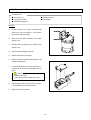
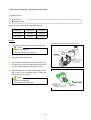
<2> For a pressure reducing valve with a solenoid valve and a pressure reducing valve with a filter.
Necessary items
● Spanner wrench
● Steel pipe or tube for piping
● Seal tape (If seal tape isn’t used, leakage may be caused)
● Joint for steel pipe or tube
Caution
Use compressed air as operating fluid. Don’t use oil pressure and water pressure.
(Actuator may be damaged.)
Use clean, filtered compressed air.
(If not, actuator may not work normally.)
When a steel pipe is used for piping, use the pipe the inside of which is treated to be rust preventive.
(The intrusion of rust into the actuator the electromagnetic valve may cause a malfunction.)
Don’t forget to remove flash in the screw part of the joint.
(A creak and air leakage may be caused.)
Don’t remove the protective plug until piping.
(The intrusion of contaminants and water may cause the malfunction of the actuator.)
Clean the pipe by brushing before piping to prevent the malfunction of the actuator.
Procedure
1)
Wind a seal tape onto the male screw of the joint
with a blank about 3mm (about 2 threads) left at
the end.
2)
Screw the joint in the piping female screw of the
actuator by hand to the full. (fig.2, 3)
3)
Screw the joint one turn with a spanner wrench.
Fig.1
Caution
Avoid excessive tightening.
(The valve can be damaged.)
4)
Fig.2
Mount a steel pipe or a tube.
- 8 -
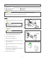
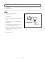
(9) Support Setting Procedure
Necessary items
● Spanner wrench
●U-type clamp (with bolt)
Caution
Set the valve support.
(The valve may be damaged because the actuator is heavy.)
Do not subject the valve to pump vibrations.
(The valve may be damaged.)
Level installation
Fix the insert metal (under the valve) and the stand with
bolts.
Spread the rubber sheet on the pipe and secure pipe with
U-type clamp.
Bolt size (insert metal : Ensat)
Nom. size
65mm (2 1/2”)
Nominal
M8
Bolt size (Stand)
Nom. size
Nominal
80mm (3”)
M16
80, 100mm(3”, 4”)
M12
100mm (4”)
M16
Perpendicular installation
Fix the insert metal (under the valve) and the stand with
bolts.
Spread the rubber sheet under the actuator and support it
with the stand.
- 9 -
● Rubber sheet
(10) Connection of limit switch procedure
Necessary items
● Screw driver (+)
● Crimp-style terminal
● Terminal crimping tool
● Connector (G1/2)
● Wire stripper
Procedure
1)
Loosen the three screws used to attach the limit
switch cover with a screwdriver (+) and remove
the cover from the limit switch.
2)
These screws are made so that they won’t detach
from the cover.
3)
Pull and remove the protective cap, made of resin,
from the cover.
4)
Draw the cable through the connector.
5)
Strip the cable with a wire stripper.
6)
Install a crimp-style terminal on the lead wire with
a terminal crimping tool.
7)
Connect the terminal screw with a screwdriver (+)
according to the internal circuit diagram show in
page 5.
Caution
Tighten up the screws.
(If not, electric leaks or shocks may occur.)
8)
Tighten the above three screws with a screw driver
(+) to install the cover on the limit switch.
9)
Tighten the cable by connector.
- 10 -
(11) Connection of solenoid valve procedure
Necessary items
● Terminal crimping tool
● Connector (G1/2)
● Screw driver (+)
● Wire stripper
Caution
Make sure that power voltage indicated on the solenoid valve and the voltage wiring to be done agree.
(Wiring with wrong voltage may cause the failure in the solenoid unit.)
Procedure
1)
Loosen the hexagon socket head cap screws, and remove
the cover.
Caution
Don’t loose O-ring.
(Electric leaks or shocks may occur.)
2)
Remove the Faston terminal inserted into coil side and the
insulating sleeve.
Caution
Insulating sleeve isn’t attached in Faston terminal.
3)
Draw the cable through the connector to the cover.
4)
Strip the cable with wire stripper.
5)
Draw the lead wire through the cover.
6)
Install the Faston terminal on the lead wire with a
terminal-crimping tool.
7)
Insert the Faston terminal into the coil side. And fit the
cover.
8)
Tighten the cover setting screws to fix it.
[The cover can be set with the wire extraction opening
turned upward or downward.(fig.3)]
9)
Tighten the cable by connector.
- 11 -
Fig.3
(12) Operating Procedure
Procedure
Caution
When AV valve is equipped with a solenoid valve, do not leave solenoid valve terminal cover off.
(Contact with the terminal will cause an electric shock.)
Check that the supply pressure of the pressure reducing valve with a filter is 0.4MPa{4.1kgf/cm2} or more.
(AV valve may not function.)
Procedure
1)
Supply air to the air supply opening.
2)
20
Check that the air supplying side and the stopper ◯
position are matching.
Caution
When AV valve is equipped with a fully opened
adjustment switch, they do not have stoppers. Check
open or close by the direction of the fluid.
3)
Stop supplying air.
Fig.2
<For the solenoid valve>
Procedure
1)
Supply the air to the solenoid valve.
2) Push the button with a finger, and confirm the action
mode shown in the following table.(fig.2)
3)
Apply regular rated voltage to the solenoid valve, and
confirm the action mode shown in the following table.
4)
Turn off the solenoid valve.
Push button
Pushed
Not pushed
Current
On
Off
Double action/Air to open
Open
Shut
Push
Air to close
Shut
Open
- 12 -
<Adjustment of opening / closing speed procedure>
○ Double action type
Necessary items
● Spanner wrench
Procedure
1)
Turn right the adjustment knob of the solenoid valve fully.
Caution
Avoid excessive tightening.
(The speed controller can be damaged.)
For Double action type with solenoid valve
Close side
Speed down
Open side
Speed up
Speed down
Speed up
2)
Supply the air to the solenoid valve.
3)
Apply regular rated voltage to solenoid valve, and turn left
the open side adjustment knob little by little.
4)
Turn off the solenoid valve, and turn left the close side
adjustment knob little by little.
5)
Repeat item 3), 4) to adjust the opening / closing speed
required.
6)
When the adjustment is finished, while holding the knob
with a finger, fix the adjustment knob by turning the
locking nut right with a spanner.
Caution
Avoid excessive tightening.
(The locking nut can be damaged.)
- 13 -
Adjustment knob
Locking nut
For Double action type with speed controller
<Adjustment of opening / closing speed procedure>
○ Single action type
Necessary items
● Spanner wrench
The actuation type changes the speed-adjustable direction.
Single action
Opening speed
Closing speed
Air to open type
Not adjustable
Adjustable
Air to close type
Adjustable
Not adjustable
Procedure
1)
Turn right the adjustment knob of the solenoid valve fully.
For Single action type with solenoid valve
Caution
Avoid excessive tightening.
(The speed controller can be damaged.)
Close side
Not used
2)
Speed down
Speed up
Supply the air to the solenoid valve.
Adjustment knob
3)
Apply regular rated voltage to solenoid valve, and turn off
the solenoid valve, then turn left the adjustment knob little
by little to adjust the opening / closing speed required.
4)
When the adjustment is finished, while holding the knob
with a finger, fix the adjustment knob by turning the
locking nut right with a spanner.
Caution
Avoid excessive tightening.
(The locking nut can be damaged.)
- 14 -
Locking nut
(13) Adjustment procedure for stopper
Necessary items
● Spanner wrench
Procedure
1)
11 by hand.
Remove the gauge cover ◯
2)
Fully open the valve.
3)
Loosen the upper part of the locking nut about a half
turn.
4)
Tighten the lower part of the locking nut by turning it
left little by little.
5)
Fix the lower part of the locking nut not to move with a
spanner, and tighten the upper part of that.
6)
Fully close the valve by air operation, and check if it
leaks or not. When the valve leaks, repeat the item 2)
to 6) until it stops.
7)
11 .
Install the gauge cover ◯
- 15 -
(14) Disassembling Method for Replacing Parts
○ Double action and air to open
Necessary items
● Protective gloves
● Safety goggles
● Spanner wrench
Caution
Wear protective gloves and safety goggles as some fluid remains in the valve.
(You may be injured.)
<Disassembly>
Procedure
1)
2)
3)
4)
5)
6)
Completely discharge fluid from pipes.
Shut the main air valve, and open the bypass valve to discharge
the air from the actuator.
Remove the air piping.
Loosen the bolt nut [A] between the body and the actuator.
28 ,◯
29 .
Remove the actuators ◯
3 by turning it 90 degrees.
Remove the diaphragm ◯
Bypass valve knob
<Assembly>
Open
Procedure
Assembly by using reverse procedures on steps 8) to 1).
(As to the body tightening torque, refer to Table 1.)
(Table 1.) Body tightening torque value
Nom. Size
65mm
Diaphragm
(2 1/2”)
material
13
Rubber
{133}
[116]
15
PTFE
{153}
[133]
Unit: N-m{kgf-cm}[lb-inch]
80mm
(3”)
100mm
(4”)
18
{184}
[160]
20
{204}
[177]
35
{357}
[310]
40
{408}
[355]
- 16 -
Close
○ Air to shut
Necessary items
● Spanner wrench
● Protective gloves
● Screwdriver (–)
● Safety goggles
● Hexagon wrench
Caution
Wear protective gloves and safety goggles as some fluid remains in the valve.
(Injury may occur.)
<Disassemble>
Procedure
1)
Completely discharge fluid from line.
2)
Remove the gauge cover.
3)
Fully close the valve by air operation.
4)
1 and the actuator ◯
30 completely.
Loosen the bolt-nut (A) between the body ◯
5)
30 .
Remove the actuator ◯
6)
Remove the diaphragm by turning it 90 degrees.
<Assemble>
Procedure
Assemble by using reverse procedures from steps 6) to 1).
(As to body tightening torque, refer to Table 1 shown on page 16.)
- 17 -
(15) Inspection items
○ Periodically inspect and maintain the AV valve in accordance with the decided schedule.
Portion to be inspected
Inspection item
1) Existence of rust, peeling of paint.
2) Tightening condition of respective threaded portions. (Loose or not)
3) Existence of abnormality in opening and closing operating sounds.
Actuator
* This actuator can be used without oiling. However, if lubricating oil is used, use
addition turbine oil specified follow:
JIS K 2213 Addition Turbine oil (ISO VG 32, 46)
Valve
1)
2)
3)
4)
Existence of scratches, cracks, deformation, and discoloring.
Existence of leakage from the valve to the outside.
Existence of leakage when the valve is opened fully at right or left.
Tightening condition of bolt (B)(loose or not).
(16) Troubleshooting and action
Problem
Cause
Action
The power source of the control panel is
turned off.
Turn on the power source.
The solenoid valve is disconnected.
Check the connection again.
(Refer to page 4)
Air is not supplied to the solenoid valve.
Supply air to solenoid valve.
The supply voltage to the solenoid valve is
wrong.
Check voltage with a tester and set
The valve does not operate by
specified voltage.
air operations
The voltage to the solenoid valve is low.
Closed bypass valve by turning the
bypass valve knob in a clockwise
direction.
The speed controller’s knob is fully turned in a Turn speed controller’s knob in a
clockwise direction.
counterclockwise direction.
The bypass valve opens.
The operation pressure is low.
- 18 -
Check the operating pressure.
Problem
Cause
The diaphragm is worn.
Fluid leaks from the valve The diaphragm or the body is scratched.
even when the valve is closed
fully.
Foreign matter is in the valve.
The operating pressure is low.
Action
Replace the diaphragm with a new
one. (Refer to page 16, 17)
Replace scratched parts with new
ones. (Refer to page 16, 17)
Disassemble valve to remove foreign
matter. (Refer to page 16, 17)
Check the operating pressure.
The bolt between the body and actuator is Tighten up the bolt to the specified
loose.
torque. (Refer to page 16).
Fluid leaks from the valve.
The diaphragm or the body is scratched.
Replace scratched parts with new one.
There is foreign matter between the diaphragm Disassemble valve to remove foreign
and the body.
matter. (Refer to page 16, 17)
The actuator operates, but the
The diaphragm or the joint metal fitting is Replace broken parts. (Refer to page
valve is not
broken.
16, 17)
opened or close.
(17) Handling of residual and waste materials
Caution
In discarding remaining or waste materials, be sure to ask waste service company.
(Poisonous gas is generated.)
- 19 -
(18) Inquiries
Nobeoka Head Office
: 2-5955, Nakanose- Cho, Nobeoka –City, Miyazaki- Pref. , Japan.
Tel : (81) 982-35-0880 Fax : (81) 982-35-9350
Tokyo Head Office
: (Furukawachiyoda Bldg.) 15-9, Uchikanda 2- Chome, Chiyoda-Ku, Tokyo, Japan.
Tel : (81) 3-3254-8177 Fax : (81) 3-3254-3474
Singapore Branch Office
: 16 Raffles Quay, #40-03 Hong Leong Building, Singapore 048581.
Tel : (65) 220-4022 Fax : (65) 324-6151
Europe Representative Office : Kaiser-Friedrich-Promenade 61 D-61348 Bad Homburg v. d. H. Germany.
Tel : (49) 6172-9175-0 Fax : (49) 6172-9175-25
ASAHI AMERICA Inc.
: 35 Green Street P.O.Box 653 , Malden, Massachusetts 02148 U.S.A.
Tel : (1) 781-321-5409 Fax : (1) 781-321-4421
- 20 -
Diaphragm Valve Type 14 Pneumatic Model Type AV
[Automatic Valve]
Information in this manual is subject to change without notice.
- 21 -
2002.2