1
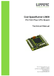
Cool RoadRunner 4
PCI-104 CPU-Board
Technical Manual
TME-P104-CRR4-R2V1.DOC
Version 2.1 / May 07
© LIPPERT Embedded Computers GmbH
Hans-Thoma-Str. 11
D-68163 Mannheim
http://www.lippert-at.com/
Technical Manual “Cool RoadRunner 4” Version 2.1
15.05.2007
Page 2 of 32
Contents
1
FUNCTIONAL SPECIFICATION..................................................................................4
1.1
General ...............................................................................................................................................4
1.2
Features..............................................................................................................................................5
1.3
Functional Block Diagram ................................................................................................................6
1.4
Processor ...........................................................................................................................................7
1.5
Northbridge ........................................................................................................................................7
1.6
Southbridge .......................................................................................................................................8
1.7
PCI Bus Interface...............................................................................................................................8
1.8
Super I/O.............................................................................................................................................8
1.9
PS/2 Keyboard Interface ...................................................................................................................9
1.10
PS/2 Mouse Interface ........................................................................................................................9
1.11
Reset-In Signal...................................................................................................................................9
1.12
USB Ports...........................................................................................................................................9
1.13
EIDE Port ............................................................................................................................................9
1.14
CRT/LCD Graphic-Controller............................................................................................................9
1.15
LVDS .................................................................................................................................................10
1.16
Gigabit Ethernet (1000BaseT) ........................................................................................................10
1.17
Audio ................................................................................................................................................10
1.18
Watchdog .........................................................................................................................................10
2
HARDWARE INSTALLATION ...................................................................................11
2.1
Adapter Cable Set............................................................................................................................11
2.2
Getting Started.................................................................................................................................11
3
SOFTWARE ...............................................................................................................12
3.1
BIOS..................................................................................................................................................12
3.1.1
Setup ................................................................................................................................................ 12
3.1.2
Special Features............................................................................................................................... 13
3.1.3
Booting from alternative device ........................................................................................................ 13
3.1.4
Reload default BIOS values ............................................................................................................. 13
3.2
Software Installation .......................................................................................................................13
4
CONNECTOR DEFINITIONS.....................................................................................14
4.1
Overview Connectors (top) ............................................................................................................14
4.1.5
Power Supply Connector.................................................................................................................. 15
4.1.6
Control – PS/2 connector ................................................................................................................. 15
4.1.7
VGA connector ................................................................................................................................. 15
4.1.8
Ethernet connector ........................................................................................................................... 15
4.1.9
Audio connector................................................................................................................................ 16
4.1.10
USB 0/1 connector ........................................................................................................................... 16
© LiPPERT Embedded Computers GmbH • Hans-Thoma-Str. 11 • 68163 Mannheim • Tel: +49 621 43214 0 • Fax: +49 621 43214 30
Technical Manual “Cool RoadRunner 4” Version 2.1
15.05.2007
Page 3 of 32
4.1.11
USB 2/3 connector ........................................................................................................................... 16
4.1.12
USB 4/5 connector ........................................................................................................................... 16
4.1.13
IDE connector................................................................................................................................... 17
4.1.14
CPU Fan Supply............................................................................................................................... 17
4.1.15
PCI Bus ............................................................................................................................................ 18
4.1.16
LED's ................................................................................................................................................ 19
4.1.16.1
LED1: IDE active .............................................................................................................................................. 19
4.1.16.2
LED2: Activity ................................................................................................................................................... 19
4.1.16.3
LED3: Speed1000 ............................................................................................................................................ 19
4.1.16.4
LED4: Link........................................................................................................................................................ 19
4.1.16.5
LED5: Watchdog .............................................................................................................................................. 19
4.1.16.6
LED6: Power .................................................................................................................................................... 19
4.1.16.7
LED7: Power Good .......................................................................................................................................... 19
4.1.16.8
LED8: Live........................................................................................................................................................ 19
4.2
Overview Connectors (bottom)......................................................................................................20
4.2.17
LVDS Dual Channel connector ........................................................................................................ 21
4.2.18
Inverter Supply ................................................................................................................................. 21
4.2.19
Display Voltage Selector .................................................................................................................. 22
4.2.20
Supervisory connector...................................................................................................................... 23
5
SOFTWARE SPECIFICATIONS ................................................................................24
5.1
System Address Map ......................................................................................................................24
5.2
Interrupts and DMA Channels........................................................................................................26
6
TECHNICAL CHARACTERISTICS............................................................................27
6.1
Electrical Specifications .................................................................................................................27
6.2
Environmental Specifications ........................................................................................................27
6.3
Mechanical Specification................................................................................................................28
6.3.21
Top View........................................................................................................................................... 28
6.3.22
Bottom View ..................................................................................................................................... 29
7
OPTIONS ...................................................................................................................30
8
TROUBLESHOOTING ...............................................................................................31
9
DOCUMENT HISTORY ..............................................................................................32
All mentioned trade marks are the property of the respective owner.
All mentioned copyrights are the property of the respective owner.
© LiPPERT Embedded Computers GmbH • Hans-Thoma-Str. 11 • 68163 Mannheim • Tel: +49 621 43214 0 • Fax: +49 621 43214 30
Technical Manual “Cool RoadRunner 4” Version 2.1
15.05.2007
Page 4 of 32
1 Functional Specification
1.1 General
The Cool RoadRunner 4 is a CPU module conforming to the PCI-104 standard definition.
At the core of the Cool RoadRunner 4 works the Intel® Pentium® M processor together with the
Intel® i82855GME (855GME) chipset. Running at up to 2000 MHz and more, this processor
consumes very little power while delivering outstanding performance at the same time. The
processor's clock frequencies will even be increased when faster CPU chips will become available.
At the other side of the performance spectrum, at lower clock frequencies, it is even possible to
operate the Cool RoadRunner 4 with a heatsink only.
The i82855GME chipset features a high performance 2D/3D graphics controller as well as an
integrated display controller with improved unified memory architecture. Displays with resolutions
up to 2048 x 1536 pixels at 75 Hz can be handled. Dual channel LVDS allows interference-free
connection of LCD modules.
The Cool RoadRunner 4 comes with PS/2 keyboard and mouse support. Two Ultra ATA 100
devices can be connected to the EIDE port. An AC´97 2.3 compatible sound I/O system is also
integrated, allowing easy construction of embedded multimedia computers.
The communication possibilities match the processor's performance: a Gigabit-Ethernet
(1000BaseT) port is integrated on the board. Further connection possibilities are provided by 6
independent USB 2.0 ports in USB host mode, which allow connection of all kinds of different USB
peripheral devices.
There is a PCI slot available for system expansion. It is a conventional 5V PCI-104 slot, which can
be used for all kinds of PCI-104 or PC/104Plus standard modules.
The system’s main memory is expandable up to 1024 MB DDR-333 (PC2700) SDRAM in the onboard SO-DIMM socket.
The board's basic functionality is supervised with the integrated status indicators. These indicators
show the state of the supply voltages, Ethernet activity as well as EIDE accesses. Also watchdog
and live will be indicated.
The Cool RoadRunner 4 is intended for embedded high performance PC applications.
© LiPPERT Embedded Computers GmbH • Hans-Thoma-Str. 11 • 68163 Mannheim • Tel: +49 621 43214 0 • Fax: +49 621 43214 30
Technical Manual “Cool RoadRunner 4” Version 2.1
15.05.2007
Page 5 of 32
1.2 Features
CPU:
•
Intel® Pentium® M Processor
Cache Memory:
•
•
On-die 32 KB Level 1 instruction and data caches
And the 1 or 2 MB Level 2 cache with Advanced Transfer Cache Architecture
Main Memory:
•
One memory slot for 64-bit memory, with up to 1 GB DDR-SODIMM
(PC2700/333MHz).
Extension slots:
•
1x 32-bit PCI-104 slot (5V)
Interfaces:
•
•
•
•
•
•
•
•
Power supply
PS/2 Keyboard
PS/2 Mouse
6x USB 2.0
Ethernet 10/100/1000 BaseT
EIDE (1x IDC44)
LVDS 18/24-bit dual channel LVDS
PCI-104 bus
Other configurations are possible at higher volumes.
Dimensions:
•
95.9mm x 115.6mm x 15mm
•
4 mounting holes
Mounting:
© LiPPERT Embedded Computers GmbH • Hans-Thoma-Str. 11 • 68163 Mannheim • Tel: +49 621 43214 0 • Fax: +49 621 43214 30
Technical Manual “Cool RoadRunner 4” Version 2.1
15.05.2007
Page 6 of 32
1.3 Functional Block Diagram
© LiPPERT Embedded Computers GmbH • Hans-Thoma-Str. 11 • 68163 Mannheim • Tel: +49 621 43214 0 • Fax: +49 621 43214 30
Technical Manual “Cool RoadRunner 4” Version 2.1
15.05.2007
Page 7 of 32
1.4 Processor
®
®
Intel Pentium M Processor, 600 MHz…2.0GHz
®
®
The Intel Pentium M processor is a high performance, low power mobile processor with several
micro-architectural enhancements over existing Intel mobile processors.
Some of the key features of this processor are:
•
•
•
•
•
•
•
•
•
Supports Intel® Architecture with Dynamic Execution
High performance, low-power core
On-die, primary 32-kbyte instruction cache and 32-kbyte write-back data cache
On-die, 1-MByte second level cache with Advanced Transfer Cache Architecture
Advanced Branch Prediction and Data Prefetch Logic
Streaming SIMD Extensions 2 (SSE2)
400-MHz, Source-Synchronous processor system bus
Advanced Power Management features including Enhanced Intel® SpeedStep® technology
Micro-FCPGA and Micro-FCBGA packaging technologies
The Intel Pentium M processor is manufactured on Intel’s advanced 0.13-micron and in 90 nm
process technology with copper interconnect. The processor maintains support for MMX™
technology and Internet Streaming SIMD instructions and full compatibility with IA-32 software. The
high performance core features architectural innovations like Micro-op Fusion and Advanced Stack
Management that reduce the number of micro-ops handled by the processor. This results in more
efficient scheduling and better performance at lower power. The on-die 32-kB Level 1 instruction
and data caches and the 1-MB or 2MB Level 2 cache with Advanced Transfer Cache Architecture
enable significant performance improvement over existing mobile processors. The processor also
features a very advanced branch prediction architecture that significantly reduces the number of
mispredicted branches. The processor’s Data Prefetch Logic speculatively fetches data to the L2
cache before an L1 cache requests occurs, resulting in reduced bus cycle penalties and improved
performance.
The Streaming SIMD Extensions 2 (SSE2) enables break-through levels of performance in
multimedia applications including 3-D graphics, video decoding/encoding, and speech recognition.
The new packed double-precision floating-point instructions enhance performance for applications
that require greater range and precision, including scientific and engineering applications and
advanced 3-D geometry techniques, such as ray tracing.
1.5 Northbridge
Intel® i82855GME, Chipset Graphics and Memory Controller Hub (GMCH)
•
•
•
•
•
•
Processor/Host Bus at 400 MHz
Memory System PC1600/PC2100/PC2700 DDR SDRAM (200/266/333MHz)
System Interrupts Intel 8259
Video Stream Decoder improved hardware motion compensation for MPEG2 and
Software DVD at 60 Fields/second and 30 frames/second full screen, encoding at
low CPU utilization
Analog display support, 350-MHz integrated 24-bit RAMDAC that can drive a
standard progressive scan analog monitor with pixel resolution up to 1600x1200 at
85 Hz and up to 2048x1536 at 75 Hz
Dual independent pipe support
© LiPPERT Embedded Computers GmbH • Hans-Thoma-Str. 11 • 68163 Mannheim • Tel: +49 621 43214 0 • Fax: +49 621 43214 30
Technical Manual “Cool RoadRunner 4” Version 2.1
o
o
15.05.2007
Page 8 of 32
Concurrent: Different images and native display timings on each
display device
Simultaneous: Same images and native display timings on each
display device
•
Dedicated LFP (local flat panel) LVDS interface, Single- or dual-channel LVDS
panel support up to UXGA panel resolution with frequency range from 25 MHz to
112 MHz (single channel/dual channel), Supports data format up to 24 bpp
•
Internal Graphics Features, 2D/3D graphics engine
For detailed information, please use the Intel® i82855GME datasheet.
1.6 Southbridge
Intel® i82801DB I/O Controller Hub 4 (ICH4)
The ICH4 provides extensive I/O support. Functions and capabilities include i.e.:
•
•
•
•
•
•
•
PCI Local Bus Specification, Revision 2.2-compliant with support for 33 MHz PCI
operations.
ACPI Power Management Logic Support
Enhanced DMA controller, Interrupt controller, and timer functions
Integrated IDE controller supports Ultra ATA100/66/33
USB host interface with support for 6 USB ports; 3 UHCI host controllers; 1 EHCI
high-speed USB 2.0 Host controller
System Management Bus (SMBus) Specification, Version 2.0 with additional
support for I2C devices
Supports Audio Codec ’97, Revision 2.3 specification (a.k.a., AC ’97 Component
Specification, Revision 2.3) Link for Audio and Telephony codecs (up to seven
channels)
1.7 PCI Bus Interface
The main features are:
•
•
•
•
•
•
Rev. 2.2 compliant implementation
Integrated PCI arbitration interface (32 bit wide, 5V-IO).
Translation of PCI cycles to ISA bus
Translation of ISA master initiated cycle to PCI
Support for burst read/write from PCI master
33 MHz PCI clock
The Cool RoadRunner 4 supports only 5 Volt signal levels on the PCI bus. Adapter boards on the
PCI-slot must tolerate this voltage.
1.8 Super I/O
The onboard Super I/O (National Semiconductor, PC87364) provides:
•
•
•
PS2 keyboard interface
PS/2 mouse interface
FAN speed control and monitor
© LiPPERT Embedded Computers GmbH • Hans-Thoma-Str. 11 • 68163 Mannheim • Tel: +49 621 43214 0 • Fax: +49 621 43214 30
Technical Manual “Cool RoadRunner 4” Version 2.1
15.05.2007
Page 9 of 32
1.9 PS/2 Keyboard Interface
The keyboard interface is located on the PS2 “Keyboard/Mouse Connector”. A standard PS2
keyboard can be used.
1.10 PS/2 Mouse Interface
The PS/2 mouse function is always active. PS/2 Mouse function can be disabled.
1.11 Reset-In Signal
The RESET-IN signal is accessible on the IDC12 Header “System Panel Connector”. To reset the
board, this signal must be pulled to GND.
1.12 USB Ports
The Cool RoadRunner 4 supports six USB ports.
Two USB ports are located on each of the three 2.0 mm IDC10 headers on the CPU-board. To use
legacy USB functions like USB boot or USB keyboard, they have to be enabled in the BIOS setup.
To enter the BIOS press <F2> key at boot time.
Integrated Peripherals – Onboard Devices
USB Controller
: Enabled/Disable
USB 2.0 Controller : Enabled/Disable
1.13 EIDE Port
An EIDE (Extended Intelligent Drive Electronics) port is provided by the chipset to connect
intelligent drives that integrate the controller (hard disk, CD-ROM etc.). This port supports LBA
(Logic Block Addressing) that allows the use of hard disks larger than 512 Mbytes. To enhance the
performance, this port supports DMA F type transfer. The EIDE port is located on a standard 44pin header (2.0 mm) for hard disks. For optimal performance, an ATA100 cable should be used.
1.14 CRT/LCD Graphic-Controller
The GMCH IGD provides a highly integrated graphics accelerator delivering high performance 2D,
3D, and video capabilities. With its interfaces to an analog display and an LVDS port (e.g. flat
panel), the GMCH can provide a complete graphics solution.
The GMCH also supports 2D hardware acceleration for block transfers of data (BLTs). The BLT
engine provides the ability to copy a source block of data to a destination and perform raster
operations (e.g., ROP1, ROP2, and ROP3) on the data using a pattern, and/or another destination.
Performing these common tasks in hardware reduces CPU load, and thus improves performance.
High bandwidth access to data is provided through the System Memory interface. The GMCH uses
tiling architecture to increase System Memory efficiency and thus maximize effective rendering
bandwidth. The Intel 855GME GMCH also improves 3D performance and quality with 3D Zone
Rendering technology.
The GMCH supports two display ports, one analog and one digital. These provide support for a
progressive scan analog monitor and a dedicated dual channel LVDS LCD panel.
The Graphics Controller has an integrated 350-MHz, 24-bit RAMDAC with maximum pixel
resolution support up to 1600x1200 at 85 Hz and up to 2048x1536 at 72 Hz.
© LiPPERT Embedded Computers GmbH • Hans-Thoma-Str. 11 • 68163 Mannheim • Tel: +49 621 43214 0 • Fax: +49 621 43214 30
Technical Manual “Cool RoadRunner 4” Version 2.1
15.05.2007
Page 10 of 32
1.15 LVDS
The Intel 855GME GMCH has an integrated dual channel LFP Transmitter interface to support
LVDS LCD panel resolutions up to UXGA with center and down spread SSC support of 0.5%, 1%,
and 2.5% utilizing an external SSC clock. The display pipe provides panel up-scaling to fit a
smaller source image onto a specific native panel size, as well as provides panning and centering
support. The LVDS port can only be driven by Pipe B, either independent or simultaneous with the
Analog Display port, respectively.
The Dedicated Dual Channel LFP LVDS interface with a frequency range of 25 MHz to 112 MHz
(single channel/dual channel) supports up to UXGA (1600x1200 at 60 Hz) LCD panel resolution
with a maximum pixel format of 24-bpp.
There is a connector on-board to supply the LC-Display's inverter.
1.16 Gigabit Ethernet (1000BaseT)
The Intel® 82541PI integrates fourth generation Gigabit MAC design with fully integrated, physical
layer circuitry to provide a standard IEEE 802.3 Ethernet interface for 1000BASE-T, 100BASE_TX,
and 10BASE-T applications (802.3, 802.3u, and 802.3ab). The controller is capable of transmitting
and receiving data at rates of 1000 Mbps, 100 Mbps or 10 Mbps.
1.17 Audio
The Cool RoadRunner 4 features a six channel audio system with an ALC203 CODEC (Realtek).
The ALC203 is an 18-bit, full duplex AC'97 2.3 compatible stereo audio CODEC designed for PC
multimedia systems.
This CODEC also supports an AC’97 2.3 compliant S/PDIF out function which allows easy
connection of the PC to consumer electronic products, such as AC3 decoder/speaker and mini
disk.
1.18 Watchdog
A watchdog is implemented by a Maxim 691 Reset/Watchdog circuit. It is accessible through some
general-purpose ports of the Southbridge controller: setting bit 7 of port 48Eh to 1 enables the
watchdog function. Thereafter the watchdog must be triggered within 600ms; otherwise, the
watchdog generates a hardware reset. Toggling bit 4 of port 48Eh triggers the watchdog.
The status of the watchdog can either be read through port 48Eh (bit 7) or be determined from pin
3 of the supervisory connector (WD-ACTIVE). In each case a high level indicates, that a watchdog
time-out has occurred. Additionally a LED indicates the occurrence of a watchdog time-out.
© LiPPERT Embedded Computers GmbH • Hans-Thoma-Str. 11 • 68163 Mannheim • Tel: +49 621 43214 0 • Fax: +49 621 43214 30
Technical Manual “Cool RoadRunner 4” Version 2.1
15.05.2007
Page 11 of 32
2 Hardware Installation
The Cool RoadRunner 4 is delivered with the correct jumper settings for proper operation. The
customer must not change the default jumper settings. Improper jumper settings will cause system
instability or system hang-ups.
Attention: The board must not be connected or disconnected to
peripherals (e.g. HDD, CDROM etc.) with the power
supply switched ON!
2.1 Adapter Cable Set
With the optionally available cable set, standard PC peripherals can be easily connected to the
board.
2.2 Getting Started
The easiest way to get the Cool RoadRunner 4 running is to use LiPPERT's CRR4 Starter Kit.
1.) Plug in SO-DIMM module into SO-DIMM-socket.
2.) Make all necessary connections by using the cables out of the starter kit. At least use CRT
monitor (VGA) and keyboard.
3.) Connect power supply (5VDC / min. 7A).
4.) Make sure that all connections have been made correctly.
5.) Switch on power supply.
6.) Enter the BIOS Setup Utility by pressing <F2> key at boot-time.
7.) Choose “Load Optimized Defaults”, save setting and reboot
© LiPPERT Embedded Computers GmbH • Hans-Thoma-Str. 11 • 68163 Mannheim • Tel: +49 621 43214 0 • Fax: +49 621 43214 30
Technical Manual “Cool RoadRunner 4” Version 2.1
15.05.2007
Page 12 of 32
3 Software
3.1 BIOS
BIOS stands for Basic Input and Output System. The BIOS is the first program to run when you
turn on your computer.
The Cool RoadRunner 4 is delivered with a standard PC BIOS. By default, all setup settings are
done to have a “ready to run” system, even without a BIOS setup backup battery. The BIOS is
located in a Flash PROM and can be easily updated on-board.
More BIOS information is available at: http://www.phoenix.com/en/customer+services/bios/awardbios/
3.1.1 Setup
Pressing the <F2> or <DEL> key at boot-time starts the setup utility.
Phoenix FirstBIOS™ Desktop CMOS Setup Utility
Standard CMOS Features
Frequency/Voltage Control
Advanced BIOS Features
Load Optimized Defaults
Advanced Chipset Features
Set Supervisor Password
Integrated Peripherals
Set User Password
Special Features
Save & Exit Setup
Power Management Setup
Exit Without Saving
PnP/PCI Configurations
Version: CRR4A006.BIN
Esc: Quit
F10: Save & Exit Setup
: Select Item
For detailed BIOS information, ask for the “BIOS-GUIDE for Thunderbird and Cool Roadrunner 4”.
© LiPPERT Embedded Computers GmbH • Hans-Thoma-Str. 11 • 68163 Mannheim • Tel: +49 621 43214 0 • Fax: +49 621 43214 30
Technical Manual “Cool RoadRunner 4” Version 2.1
15.05.2007
Page 13 of 32
3.1.2 Special Features
For the Cool RoadRunner 4 is an extension module called "Bridge to ISA" (B2I) available. This
module includes many new hardware features for the Cool RoadRunner 4. To configure the
attached hardware, several parameters can be changed with the BIOS setup utility. For more
details, please refer to the B2I user manual.
Phoenix FirstBIOS™ Desktop CMOS Setup Utility
Special Features
BIOS PLUGIN
20050530
DiskOnChip Base Address
[Disabled]
FDD Controller
[Disabled]
Serial Port 1
Serial Port 1 Mode
[Disabled]
[RS-232]
Serial Port 2
Serial Port 2 Mode
[Disabled]
[RS-232]
Parallel Port
Parallel Port Mode
[Disabled]
[SSP]
Program FPGA by BIOS
[Disabled]
Item Help
Menu Level >
3.1.3 Booting from alternative device
Pressing the <ESC> key at power-up starts the Boot Menu. Choose one of the listed bootable
devices for booting.
3.1.4 Reload default BIOS values
The default values of the BIOS can be automatically reloaded at boot time. Therefore the key
<0 / INSERT> on the NUM pad has to be pressed before the system is turned on. While pressing
this key and turning the system on, the default values will be loaded.
After reloading the default BIOS values and rebooting you should start the BIOS Setup Utility.
Choose “Load Optimized Defaults” to get the best setup for CRR4.
3.2 Software Installation
The drivers for the Cool Roadrunner 4 are available either on the product CD-ROM or at
LiPPERT's Website (www.lippert-at.com). To install them correctly, please read the instructions on
the driver disks before installing.
The latest drivers are always available from Intel's website:
http://downloadfinder.intel.com/scripts-df/Support_Intel.asp
© LiPPERT Embedded Computers GmbH • Hans-Thoma-Str. 11 • 68163 Mannheim • Tel: +49 621 43214 0 • Fax: +49 621 43214 30
Technical Manual “Cool RoadRunner 4” Version 2.1
15.05.2007
Page 14 of 32
4 Connector Definitions
4.1 Overview Connectors (top)
© LiPPERT Embedded Computers GmbH • Hans-Thoma-Str. 11 • 68163 Mannheim • Tel: +49 621 43214 0 • Fax: +49 621 43214 30
Technical Manual “Cool RoadRunner 4” Version 2.1
15.05.2007
Page 15 of 32
4.1.5 Power Supply Connector
Connector type: AMP type 350211-1 connector (X28)
PIN
1
2
3
4
Signal
+12V (only for PCI slot and Inverter power supply)
GND
GND
+5V
1
3
2
4.1.6 Control – PS/2 connector
Connector type: IDC10 pin header 2.0 mm (X20)
PIN
1
3
5
7
9
Signal
PC Speaker Out
Reset IN
KeybDAT
GND
Vext. Bat Input
PIN
2
4
6
8
10
Signal
MouseCLK
MouseDAT
KeybCLK
+5V out
PowerButton IN
1
2
3
4
5
6
7
8
9
10
1
2
Vext.Bat Input: typ. 3VDC (2.5…3,6VDC), max. current 10uA
4.1.7 VGA connector
Connector type: IDC10 pin header 2.0 mm (X8)
PIN
1
3
5
7
9
Signal
Red
Green
Blue
H-Sync
V-Sync
PIN
2
4
6
8
10
Signal
Video-GND
key
DDCCLK
DDCDAT
GND
3
5
6
7
8
9
10
1
2
3
4
4.1.8 Ethernet connector
Connector type: IDC10 pin header 2.0 mm (X13)
PIN
1
3
5
7
9
Signal
MX1MX2n.c.
MX3MX4-
PIN
2
4
6
8
10
Signal
MX1+
MX2+
key
MX3+
MX4+
5
7
8
9
10
© LiPPERT Embedded Computers GmbH • Hans-Thoma-Str. 11 • 68163 Mannheim • Tel: +49 621 43214 0 • Fax: +49 621 43214 30
4
Technical Manual “Cool RoadRunner 4” Version 2.1
15.05.2007
Page 16 of 32
4.1.9 Audio connector
Connector type: IDC10 pin header 2.0 mm (X17)
PIN
1
3
5
7
9
4.1.10
Signal
Line In Right
Line Out Right
CD In Right
Mic In
SPDIF Out
PIN
2
4
6
8
10
Signal
Line In Left
Line Out Left
CD In Left
key
Audio GND
1
2
3
4
5
6
7
9
10
1
2
3
4
5
6
7
8
USB 0/1 connector
Connector type: IDC10 pin header 2.0 mm (X14)
PIN
1
3
5
7
9
4.1.11
Signal
VCC USB0
USB0USB0+
GND
n.c.
PIN
2
4
6
8
10
Signal
VCC USB1
USB1USB1+
GND
key
9
USB 2/3 connector
Connector type: IDC10 pin header 2.0 mm (X15)
PIN
1
3
5
7
9
4.1.12
Signal
VCC USB2
USB2USB2+
GND
n.c.
PIN
2
4
6
8
10
Signal
VCC USB3
USB3USB3+
GND
key
1
2
3
4
5
6
7
8
9
USB 4/5 connector
Connector type: IDC10 pin header 2.0 mm (X16)
PIN
1
3
5
7
9
Signal
VCC USB4
USB4USB4+
GND
n.c.
PIN
2
4
6
8
10
Signal
VCC USB5
USB5USB5+
GND
key
1
2
3
4
5
6
7
8
9
© LiPPERT Embedded Computers GmbH • Hans-Thoma-Str. 11 • 68163 Mannheim • Tel: +49 621 43214 0 • Fax: +49 621 43214 30
Technical Manual “Cool RoadRunner 4” Version 2.1
4.1.13
15.05.2007
Page 17 of 32
IDE connector
Connector type: IDC44pin header 2.0 mm (X9)
1
PIN
1
3
5
7
9
11
13
15
17
19
21
23
25
27
29
31
33
35
37
39
41
43
Signal
RST#
Data7
Data6
Data5
Data4
Data3
Data2
Data1
Data0
GND
DRQ
IOW#
IOR#
RDY
DACK#
IRQ
Adr1
Adr0
CS1#
LED
+5V
GND
4.1.14
PIN
2
4
6
8
10
12
14
16
18
20
22
24
26
28
30
32
34
36
38
40
42
44
Signal
GND
Data8
Data9
Data10
Data11
Data12
Data13
Data14
Data15
n.c.
GND
GND
GND
CSEL
GND
n.c.
PDIAG#
Adr2
CS3#
GND
+5V
GND
2
3
4
5
6
7
8
9
10
11
12
13
14
15
16
17
18
19
22
21
22
23
24
25
26
27
28
29
30
31
32
33
34
35
36
37
38
39
40
41
42
43
44
CPU Fan Supply
Connector type: DF13-3P-1.25V, Hirose (X12)
PIN
1
2
3
Signal
Speed Signal from fan (yellow)
+5VDC (red)
GND (black)
3
2
1
Current at +5VDC output: max.500mA
© LiPPERT Embedded Computers GmbH • Hans-Thoma-Str. 11 • 68163 Mannheim • Tel: +49 621 43214 0 • Fax: +49 621 43214 30
Technical Manual “Cool RoadRunner 4” Version 2.1
4.1.15
15.05.2007
Page 18 of 32
PCI Bus
Connector type: PCI-104 PCI connector (X5)
Pin
1
2
3
4
5
6
7
8
9
10
11
12
13
14
15
16
17
18
19
20
21
22
23
24
25
26
27
28
29
30
A
B
C
D
GND
VI/O
AD05
C/BE0#
GND
AD11
AD14
NC (+3.3V)
SERR#
GND
STOP#
NC (+3.3V)
FRAME
GND
AD18
AD21
NC (+3.3V)
IDSEL0
AD24
GND
AD29
+5V
REQ0#
GND
GNT1#
+5V
CLK2
GND
+12 Volts
NC(-12V)
Reserved
AD02
GND
AD07
AD09
VI/O
AD13
C/BE1#
GND
PERR#
NC (+3.3V)
TRDY#
GND
AD16
NC (+3.3V)
AD20
AD23
GND
C/BE3#
AD26
+5V
AD30
GND
REQ2#
VI/O
CLK0
+5V
INTD#
INTA#
REQ3#
+5V
AD01
AD04
GND
AD08
AD10
GND
AD15
Reserved
NC (+3.3V)
LOCK#
GND
IRDY#
NC (+3.3V)
AD17
GND
AD22
IDSEL1
VI/O
AD25
AD28
GND
REQ1#
+5V
GNT2#
GND
CLK3
+5V
INTB#
GNT3#
AD00
+5V
AD03
AD06
GND
M66EN
AD12
NC (+3.3V)
PAR
Reserved
GND
DEVSEL#
NC (+3.3V)
C/BE2#
GND
AD19
NC (+3.3V)
IDSEL2
IDSEL3
GND
AD27
AD31
VI/O
GNT0#
GND
CKL1
GND
RST#
INTC#
GND
A
B C
1
1
1
D
1
2
2
2
2
3
3
3
3
4
4
4
4
5
5
5
5
6
6
6
6
7
7
7
7
8
8
8
8
9
9
9
9
10
10
10
10
11
11
11
11
12
12
12
12
13
13
13
13
14
14
14
14
15
15
15
15
16
16
16
16
17
17
17
17
18
18
18
18
19
19
19
19
20
20
20
20
21
21
21
21
22
22
22
22
23
23
23
23
24
24
24
24
25
25
25
25
26
26
26
26
27
27
27
27
28
28
28
28
29
29
29
29
30
30
30
30
Note: All “VI/O” pins are connected to +5 Volts.
This board does not support -12 Volts.
Note: All signals named "NC (+3.3V)" are in fact not connected. It is possible to jumper 3.3V to all
pins. However, this is a configuration option and is only available for larger orders.
© LiPPERT Embedded Computers GmbH • Hans-Thoma-Str. 11 • 68163 Mannheim • Tel: +49 621 43214 0 • Fax: +49 621 43214 30
Technical Manual “Cool RoadRunner 4” Version 2.1
4.1.16
15.05.2007
Page 19 of 32
LED's
4.1.16.1 LED1: IDE active
Color: yellow
Function: IDE device active (ON)
4.1.16.2 LED2: Activity
Color: red
Function: Ethernet activity (ON)
4.1.16.3 LED3: Speed1000
Color: yellow
Function: Ethernet speed is 1Gbit (ON)
4.1.16.4 LED4: Link
Color: green
Function: Ethernet Link (ON)
4.1.16.5 LED5: Watchdog
Color: red
Function: Watchdog activated (ON)
4.1.16.6 LED6: Power
Color: green
Function: 5VDC Power connected (ON)
4.1.16.7 LED7: Power Good
Color: green
Function: Power Good (ON)
4.1.16.8 LED8: Live
Color: green
Function: Live Signal (ON)
© LiPPERT Embedded Computers GmbH • Hans-Thoma-Str. 11 • 68163 Mannheim • Tel: +49 621 43214 0 • Fax: +49 621 43214 30
Technical Manual “Cool RoadRunner 4” Version 2.1
15.05.2007
Page 20 of 32
4.2 Overview Connectors (bottom)
© LiPPERT Embedded Computers GmbH • Hans-Thoma-Str. 11 • 68163 Mannheim • Tel: +49 621 43214 0 • Fax: +49 621 43214 30
Technical Manual “Cool RoadRunner 4” Version 2.1
4.2.17
15.05.2007
Page 21 of 32
LVDS Dual Channel connector
Connector type: DF14-30P-1.25H, Hirose (X5)
PIN
1
2
3
4
5
6
7
8
9
10
11
12
13
14
15
16
17
18
19
20
21
22
23
24
25
26
27
28
29
30
1
Signal
VDD (3.3V, opt.5V)
VDD (3.3V, opt.5V)
GND
GND
TXA3 TXA3 +
TXACLK TXACLK +
GND
TXA2 TXA2 +
TXA1 TXA1 +
TXA0 TXA0 +
GND
TXB3 TXB3 +
TXBCLK TXBCLK +
GND
TXB2 TXB2 +
TXB1 TXB1 +
TXB0 TXB0 +
GND
LVDS DDCCLK
LVDS DDCDAT
4.2.18
Inverter Supply
Connector type: Hirose DF13 8 pin (X6)
PIN
1
2
3
4
5
6
7
8
Signal
+12V DC
+12V DC
+5V DC
+5V DC
Backlight enable (level: 3,3V)
Backlight enable (level: 5V/12V)
GND
GND
© LiPPERT Embedded Computers GmbH • Hans-Thoma-Str. 11 • 68163 Mannheim • Tel: +49 621 43214 0 • Fax: +49 621 43214 30
1
2
3
4
5
6
7
8
Technical Manual “Cool RoadRunner 4” Version 2.1
4.2.19
15.05.2007
Page 22 of 32
Display Voltage Selector
Jumper X4, Location is behind X5 (LVDS connector).
Use a 2 mm jumper between 1-3 or 3-5 to select the backlight voltage.
Use a 2 mm jumper between 2-4 or 4-6 to select the display voltage.
Connector type: IDC6 jumper 2.00 mm.
Pin
Signal name
Pin
Signal name
1
+3,3V DC
2
+12V DC
3
Display voltage
4
Backlight voltage
5
+5V DC
6
+5V DC
Default setup:
Display Voltage is +3,3V DC
Backlight Voltage is +5V DC
Example 1:
5V for the inverter at 3,3V display
Pin
Signal name
Pin
Signal name
1
+3,3V DC
2
+12V DC
3
Display voltage
4
Backlight voltage
5
+5V DC
6
+5V DC
Example 2:
12V for the inverter at 3,3V display
Pin
Signal name
Pin
Signal name
1
+3,3V DC
2
+12V DC
3
Display voltage
4
Backlight voltage
5
+5V DC
6
+5V DC
Note: Setup depends on your display and inverter type. Check first the datasheets.
© LiPPERT Embedded Computers GmbH • Hans-Thoma-Str. 11 • 68163 Mannheim • Tel: +49 621 43214 0 • Fax: +49 621 43214 30
Technical Manual “Cool RoadRunner 4” Version 2.1
4.2.20
15.05.2007
Page 23 of 32
Supervisory connector
Connector type: Hirose DF13 8 pin (X18)
Pin
1
2
3
4
5
6
7
Signal
5VSBY Power
3.3VSBY Power
Watchdog active
Live signal#
IDE active
5V Power
FAN revolution
8
SMB clock
9
SMB data
10
Ext. SMI#
11
12
GPIO43
Ethernet SPEED1000
LED#
13
Ethernet ACTIVITY LED#
14
Ethernet LINK LED#
15
GND
Type
OD
PD5V
1k8
O
3.3V
O
5V
Description
5.0 Volt Stand-by power.
3.3 Volt Stand-by power.
Shows the status of the watchdog (see
also Section 1.18).
Indicates board status. After board
initialization this signal goes active (Low)
This pin indicates accesses to the IDE
port. This output is Active High.
5.0 Volt power
I/OD This signal is directly connected to X12PU3.3V Pin 1. If no onboard fan is used, you can
10k
apply a fan speed signal to this pin.
OD
ACCESS.bus Clock Signal from Super
PU3.3V I/O Controller PC87364.
10k
I/OD ACCESS.bus Data Signal from Super
PU3.3V I/O Controller PC87364.
10k
OD
System Management Interrupt from
PU3.3V Super I/O Controller PC87364.
10k
I/O
GPIO43 of ICH4
OD
The Speed LED pin will be Low at 1000
PU3.3V Mbps connection.
1k5
OD
The Activity LED pin will be Low if either
PU3.3V transmit or receive activity is present.
1k5
OD
The Link LED pin will be Low when a
PU3.3V valid link is detected.
1k5
Common ground
© LiPPERT Embedded Computers GmbH • Hans-Thoma-Str. 11 • 68163 Mannheim • Tel: +49 621 43214 0 • Fax: +49 621 43214 30
1
2
3
4
5
6
7
8
9
10
11
12
13
14
15
Technical Manual “Cool RoadRunner 4” Version 2.1
15.05.2007
Page 24 of 32
5 Software Specifications
5.1 System Address Map
This section describes the mapping of the CPU memory and I/O address spaces. Also covered in
this section are the PCI configuration space mapping.
Note: Depending on enabled or disabled
functions in the BIOS, other or more
resources may be used!
Memory address map
Address Range
(Dec)
1024K – XXXXXK
Address Range
(Hex)
100000 – XXXXXX
Size
Description
xxxx
Extended Memory
961K – 1024K
0F0000 – 0FFFFF
64K
System Bios
865K – 960K
0D8000 – 0EFFFF
96K
Free
832K – 864K
0D0000 – 0D7FFF
32K
Mapped RAM
818K – 831K
0CC800 – 0CFFFF
~142K
Free
768K – 817K
0C0000 – 0CC7FF
~50K
Adapter ROM
704K – 768K
0B0000 – 0BFFFF
64K
VGA Adapter
640K – 704K
0A0000 – 0AFFFF
64K
VGA Adapter
0K – 640K
0 – 9FFFF
640K
Conventional Memory
© LiPPERT Embedded Computers GmbH • Hans-Thoma-Str. 11 • 68163 Mannheim • Tel: +49 621 43214 0 • Fax: +49 621 43214 30
Technical Manual “Cool RoadRunner 4” Version 2.1
15.05.2007
Page 25 of 32
I/O address map
The system chipset implements a number of registers in I/O address space. These registers
occupy the following map in the I/O space (depending on enabled or disabled functions in the
BIOS other or more resources may be used).
Address Range (Hex)
Size (Hex)
Description
0000-000F
16 Bytes
DMA Controller 1 (8237)
0020-0021
2 Bytes
Interrupt Controller 1 (8259)
0040-0043
4 Bytes
Timer Controller (8254)
0060
1 Bytes
Keyboard Controller Data Byte
0061
1 Byte
Speaker Control
0064
1 Byte
Kbd Ctlr, CMD,STAT Byte
0070-0071
2 Bytes
Real Time Clock
0078
1 Byte
internal
0079
1 Byte
Watchdog
0080-0091
18 Bytes
DMA Page Registers
00A0-00A1
2 Bytes
Interrupt Controller 2 (8259)
00C0-00DF
32 Bytes
DMA Controller 1 (8237)
00F0-00FF
16 Byte
Math Coprozessor
0170-0177
8 Bytes
(Secondary IDE Channel)
01F0-01F7
8 Bytes
(Primary IDE Channel)
02F8-02FF
8 Bytes
(Serial Port 2)
0376
1 Byte
IDE Controller
0378-037F
8 Bytes
(Parallel Port 1)
03B0- 03BB
12 Bytes
VGA Registers
03C0-03DF
32 Bytes
VGA Registers
03F0-03F5
6 Bytes
(Floppy Controller Registers)
03F6
1 Byte
IDE Command Port
03F7
1 Byte
(Floppy Command Port)
03F8-03FF
8 Bytes
(Serial Port 1)
0400-04BF
192 Bytes
PCI Bus
04D0-04D1
2 Bytes
PCI Bus
0CF8-0CFF
8 Bytes
PCI Bus
9000-9FFF
4096 Bytes
PCI-PCI Bridge
A000 – A01E
31 Bytes
USB Controller
A400 – A41E
31 Bytes
USB Controller
A800 – A81E
31 Bytes
USB Controller
AC00 – AC06
7 Bytes
VGA Adapter
F000 – F00E
15 Bytes
IDE Controller
© LiPPERT Embedded Computers GmbH • Hans-Thoma-Str. 11 • 68163 Mannheim • Tel: +49 621 43214 0 • Fax: +49 621 43214 30
Technical Manual “Cool RoadRunner 4” Version 2.1
15.05.2007
Page 26 of 32
5.2 Interrupts and DMA Channels
Interrupts
IRQ
System Resource
NMI
Parity Error
0
Timer
1
Keyboard
2
Interrupt Controller 2
3
Serial Port 2 (extension board)
4
Serial Port 1 (extension board)
5
Not used
6
Floppy (extension board)
7
Not used
8
Real Time Clock
9
USB Controller
10
VGA Adapter
11
USB Controller
12
Not used
13
Math coprocessor
14
IDE Controller
15
IDE Controller (not used)
DMA channels
DMA
Data width
System Resource
0
8 bits
User available
1
8 bits
User available
2
8 bits
Floppy (extension board)
3
8 bits
(Parallel Port, extension board)
4
Reserved, Cascade Channel
5
16 bits
User Available
6
16 bits
User Available
7
16 bits
User Available
© LiPPERT Embedded Computers GmbH • Hans-Thoma-Str. 11 • 68163 Mannheim • Tel: +49 621 43214 0 • Fax: +49 621 43214 30
Technical Manual “Cool RoadRunner 4” Version 2.1
15.05.2007
Page 27 of 32
6 Technical Characteristics
6.1 Electrical Specifications
Supply voltage:
+5 VDC
(+12VDC only for PCI slot and inverter-power supply)
Supply voltage ripple:
± 5%
Supply current
1.0 GHz:
approx. 4A at +5V
1.4 GHz:
approx. 5A at +5V
1.8 GHz:
approx. 7A at +5V
6.2 Environmental Specifications
Operating:
Temperature range:
-20…60 °C
Temperature change:
max. 10K / 30 minutes
Humidity (relative):
10…95 % (non-condensing)
Pressure:
450…1100 hPa
Non-Operating/Storage/Transport:
Temperature range:
-40…+85°C
Temperature change:
max. 10K / 30 minutes
Humidity (relative):
5%...95% (non-condensing)
Pressure:
450...1100 hPA
© LiPPERT Embedded Computers GmbH • Hans-Thoma-Str. 11 • 68163 Mannheim • Tel: +49 621 43214 0 • Fax: +49 621 43214 30
Technical Manual “Cool RoadRunner 4” Version 2.1
15.05.2007
Page 28 of 32
6.3 Mechanical Specification
Dimensions (LxW) :
Height :
Weight :
6.3.21
95.9mm x 115.6mm
(including I/O extension)
15 mm
approx. 140g
Top View
Notes:
- Values in () indicate the height of the component
- All dimensions are in inch
© LiPPERT Embedded Computers GmbH • Hans-Thoma-Str. 11 • 68163 Mannheim • Tel: +49 621 43214 0 • Fax: +49 621 43214 30
Technical Manual “Cool RoadRunner 4” Version 2.1
6.3.22
15.05.2007
Page 29 of 32
Bottom View
Notes:
- Values in () indicate the height of the component
- All dimensions are in inch
© LiPPERT Embedded Computers GmbH • Hans-Thoma-Str. 11 • 68163 Mannheim • Tel: +49 621 43214 0 • Fax: +49 621 43214 30
Technical Manual “Cool RoadRunner 4” Version 2.1
15.05.2007
Page 30 of 32
7 Options
There are various options available for the Cool RoadRunner 4.
Please check their availability before ordering.
•
Heatsink
•
Cable set
•
CompactFlash Adapter
•
Board extension modules (serial, DOC, FireWire, WLAN...)
•
B2I Adapter
© LiPPERT Embedded Computers GmbH • Hans-Thoma-Str. 11 • 68163 Mannheim • Tel: +49 621 43214 0 • Fax: +49 621 43214 30
Technical Manual “Cool RoadRunner 4” Version 2.1
15.05.2007
Page 31 of 32
8 Troubleshooting
PROBLEM: The system will not come up at all, the display is blank and the computer does not
make any beep sounds from the speaker.
First steps if the Board does not boot:
•
•
•
•
•
•
•
•
•
•
Check the power connectors to the board, monitor and additional devices.
Are all cables plugged on the correct connector and in the correct orientation? The board
may not boot if some of the cables are not plugged in correctly!
Is a RAM module inserted?
Check the power supply. Is the supply voltage correct for the board? If you are not sure,
read the manual. Try plugging in a different power supply or multi-meter to check the power
a wrong supply voltage can easily FRY a computer and other electrical devices.
Is your display ok? Is the monitor powered on? Is the monitor's video cable plugged into
the video connector? Double-check the brightness and contrast settings. Plug the monitor
into another computer if possible to verify the monitor isn't the problem.
Apply power to the board while holding down the ”Insert” key at the numeric block of the
keyboard. This will load the manufacturer BIOS defaults.
Remove all additional devices from the system. Only the processor board, power supply,
monitor and the keyboard should remain in the system.
Replace the system RAM
If all else has failed, replace the CPU Board itself.
If system comes up then load at first the OPTIMIZED DEFAULTS in the BIOS setup and
reboot.
© LiPPERT Embedded Computers GmbH • Hans-Thoma-Str. 11 • 68163 Mannheim • Tel: +49 621 43214 0 • Fax: +49 621 43214 30
Technical Manual “Cool RoadRunner 4” Version 2.1
15.05.2007
Page 32 of 32
9 Document History
Filename
Date
Edited by
Change
TME-P104-CRR4-R0V0
04-05-18
Alfred Glass
Draft
TME-P104-CRR4-R0V1
04-09-09
Alfred Glass
Some corrections
TME-P104-CRR4-R0V2
04-09-09
Alfred Glass
Power supply connector corrected
TME-P104-CRR4-R0V3
05-04-05
Alfred Glass
New block diagram
TME-P104-CRR4-R0V4
05-04-11
Jürgen Stauffer
TME-P104-CRR4-R0V5
05-04-11
Alfred Glass
Electric. Spec. for 1.0 and 2.0GHz
TME-P104-CRR4-R1V0
05-07-13
Alfred Glass
New PCB rev. 1v0
TME-P104-CRR4-R2V0
06-01-14
Alfred Glass
PCB rev. 2v0, troubleshooting, getting
started
TME-P104-CRR4-R2V0
07-05-15
Alfred Glass
Description for X4
Supervisory connector description
© LiPPERT Embedded Computers GmbH • Hans-Thoma-Str. 11 • 68163 Mannheim • Tel: +49 621 43214 0 • Fax: +49 621 43214 30