1
A Network Enabled,
Centralized DSP,
Distributed Speaker System
Earl Maier, Daren Ruben, Talitha Rubio, & Matt Webb
Group #13, Senior Design Fall 2011
Sponsorship: Alcorn McBride Inc. and Workforce
Central Florida
Table of Contents
1 Executive Summary ..................................................................................... 1 2 Project Description ...................................................................................... 2 2.1 2.2 2.3 3 Project Motivation and Goals ......................................................................... 2 Objectives ........................................................................................................ 3 Project Requirements and Specifications .................................................... 4 Research ....................................................................................................... 6 3.1 Power Supply................................................................................................... 6 3.1.1 Regulated Power –vs- Unregulated .............................................................. 6 3.1.2 Switching vs Linear Regulator ....................................................................... 7 3.1.3 Supply Noise ................................................................................................. 8 3.2 Digital Signal Processing ............................................................................. 10 3.2.1 Processor .................................................................................................... 10 3.2.1.1 Requirements ................................................................................................. 10 3.2.1.2 Part Choice ..................................................................................................... 11 3.2.1.3 Features .......................................................................................................... 17 3.2.1.3.1 Programming Method ................................................................................ 17 3.2.1.3.2 Ports Available ........................................................................................... 18 3.2.1.4 Real-Time OS ................................................................................................. 23 3.2.2 Algorithms ................................................................................................... 24 3.2.2.1 Project Requirements ..................................................................................... 24 3.2.2.2 LPF & HPF Methods ....................................................................................... 26 3.2.2.3 Band pass and Shelving ................................................................................. 27 3.2.2.4 Digital Implementation .................................................................................... 28 3.2.3 Analog to Digital Converters (ADC) ............................................................. 28 3.2.3.1 Requirements ................................................................................................. 28 3.2.3.2 Part Choice ..................................................................................................... 29 3.2.3.3 CODEC ........................................................................................................... 32 3.3 Microprocessors ........................................................................................... 34 3.3.1 Project Requirements .................................................................................. 34 3.3.1.1 DSP Box ......................................................................................................... 34 3.3.1.2 Breakout Box .................................................................................................. 36 3.3.2 Part Choice .................................................................................................. 37 3.3.2.1 DSP Box ......................................................................................................... 37 3.3.2.2 Breakout Box .................................................................................................. 37 3.4 Audio Transfer Methods and Protocols ...................................................... 38 3.4.1 Balancing Audio Signal ............................................................................... 38 3.4.2 Part Choice .................................................................................................. 39 3.4.3 Audio over Ethernet ..................................................................................... 41 3.4.3.1 DSP Box ......................................................................................................... 42 3.4.3.2 Breakout Box .................................................................................................. 42 3.4.4 Dante ........................................................................................................... 43 3.4.5 Brooklyn II Module ....................................................................................... 44 3.4.6 Digital Audio Formats & Standards ............................................................. 46 3.4.6.1 Time-Division Multiplexing .............................................................................. 46 3.4.6.2 Biphase-Mark Code (BMC) ............................................................................. 46 3.5 Amplification.................................................................................................. 47 3.5.1 Project Requirements .................................................................................. 47 3.5.2 Amplifier types ............................................................................................. 48 3.5.3 Part Choice .................................................................................................. 50 ii
3.6 Monitoring & Sensors ................................................................................... 51 3.6.1 Purpose ....................................................................................................... 51 3.6.2 Temperature Sensing Methods ................................................................... 52 3.7 Printed Circuit Board .................................................................................... 53 3.7.1 Orcad ........................................................................................................... 53 3.7.2 Layer consideration ..................................................................................... 54 3.8 User Interface ................................................................................................ 54 4 Design ......................................................................................................... 58 4.1 Stellaris .......................................................................................................... 58 4.1.1 DSP Box ...................................................................................................... 58 4.1.1.1 Hardware Interfacing ...................................................................................... 58 4.1.1.2 Software Interfacing ........................................................................................ 61 4.1.1.2.1 Stellaris-Blackfin SPI Interface .................................................................. 61 4.1.1.2.2 Data Structures .......................................................................................... 69 4.1.1.3 User Interface Design Discussion ................................................................... 70 4.1.1.3.1 Web User Interface Design Discussion ..................................................... 70 4.1.1.3.2 Web User Interface API Design Discussion .............................................. 79 4.1.1.3.3 Physical User Interface Design .................................................................. 81 4.1.2 Breakout Box ............................................................................................... 82 4.1.2.1 Hardware Interfacing ...................................................................................... 82 4.1.2.2 Software Interfacing ........................................................................................ 84 4.2 Blackfin .......................................................................................................... 90 4.2.1 Hardware Interfacing ................................................................................... 90 4.2.2 Software Interfacing .................................................................................... 99 4.3 Power Supply Design.................................................................................. 100 4.3.1 Power Supply Requirements ..................................................................... 100 4.4 Gigabit Ethernet Switch .............................................................................. 107 4.5 Audio Inputs and Outputs .......................................................................... 109 4.5.1 CODEC & Digital Transceiver ................................................................... 109 4.5.2 Balanced Audio Inputs .............................................................................. 112 4.5.3 Unbalanced Audio Inputs .......................................................................... 112 4.5.4 Audio Outputs ............................................................................................ 114 4.5.5 Front Panel ................................................................................................ 116 4.6 Master, Frame, and Bit Clock Distribution ................................................ 119 4.7 Dual PCB Use .............................................................................................. 120 4.7.1 Production Resistor MUX’s ....................................................................... 121 4.7.2 Breakout Box Signal Flow Considerations ................................................ 121 5 Design Summary ...................................................................................... 122 5.1 Hardware ...................................................................................................... 122 5.2 Software ....................................................................................................... 123 5.2.1 DSP Box .................................................................................................... 123 5.2.2 Breakout Box ............................................................................................. 124 6 Prototyping ............................................................................................... 125 6.1 6.2 7 Project Testing ......................................................................................... 128 7.1 7.2 8 DSP Box ....................................................................................................... 125 Breakout Box ............................................................................................... 126 Breakout Box Testing ................................................................................. 128 DSP Box Testing ......................................................................................... 130 User Interface ........................................................................................... 133 iii
8.1 8.2 8.3 8.4 8.5 9 Requirements .............................................................................................. 133 Amptraxx2/Blackfin Start Up ...................................................................... 134 Stellaris Start Up and Integration .............................................................. 138 Screen and Knob ......................................................................................... 140 User Interface .............................................................................................. 141 Administration .......................................................................................... 144 9.1 9.2 Milestone Discussion.................................................................................. 144 Budget and Finance Discussion ................................................................ 145 10 Project Summary and Conclusion ...................................................... 146 11 Appendix A – Schematics ......................................................................... I ................................................................................................................................ I ..............................................................................................................................IV ...............................................................................................................................V ..............................................................................................................................VI .............................................................................................................................VII ............................................................................................................................VIII ..............................................................................................................................IX ...............................................................................................................................X ..............................................................................................................................XI .............................................................................................................................XII ............................................................................................................................XIII 12 Appendix B – References .................................................................... XIV iv
Figure Listing
Figure 1: Front Panel of Breakout Box .................................................................. 4 Figure 2: Back Panel of Breakout Box .................................................................. 4 Figure 3: Front Panel of DSP Box ......................................................................... 5 Figure 4 Back Panel of DSP Box .......................................................................... 5 Figure 5: Switching Regulator Operation .............................................................. 8 Figure 6: Ground Bounce Primer by Vikas Kumar ................................................ 9 Figure 7: Execution Time Comparison ................................................................ 13 Figure 8: Energy Consumption Comparison ....................................................... 14 Figure 9: Cost Efficiency Comparison ................................................................. 14 Figure 10: Memory Usage Comparison .............................................................. 15 Figure 11: SPI Interface Block Diagram .............................................................. 19 Figure 12: SPORTx Block Diagram ..................................................................... 20 Figure 13: Channel Select Registers ................................................................... 22 Figure 14: TWI Interface Block Diagram ............................................................. 23 Figure 15: TWI Transfer Protocol ........................................................................ 23 Figure 16: Biquad Filter Diagram and Equations ................................................ 26 Figure 17: Biquad Filter Diagram after Factorization of b0 .................................. 28 Figure 18: TDM Serial audio Format ................................................................... 33 Figure 19: Timing: I2C Writing ............................................................................. 34 Figure 20: Timing: I2C Reading ........................................................................... 34 Figure 21 Balanced Signal .................................................................................. 39 Figure 22: Internal Schematic of INA137 and DRV134 ....................................... 40 Figure 23: Ethernet Data Standard ..................................................................... 42 Figure 24: TDM Framing ..................................................................................... 45 Figure 25:Accuracy to Distance/Radius Chart .................................................... 53 Figure 26: Stellaris LM3S8962 Power Schematic ............................................... 58 Figure 27: Stellaris Microcontroller Schematic .................................................... 59 Figure 28: LM3S8962 Hard Reset Circuitry ........................................................ 61 Figure 29: Homescreen User Interface in iPhone Simulator ............................... 71 Figure 30: Homescreen User Interface in Chrome .............................................. 71 Figure 31: Matrix Routing View on iPhone .......................................................... 72 Figure 32: Matrix Routing View on Chrome ....................................................... 72 Figure 33: Select Box on iPhone ......................................................................... 73 Figure 34: Matrix "Apply" Button.......................................................................... 73 Figure 35: Process Input selection on iPhone ..................................................... 73 Figure 36: Process Input selection on Chrome ................................................... 73 Figure 37: Processing type selection per channel on iPhone ............................. 74 Figure 38: Equalization screen on iPhone ........................................................... 75 Figure 39: Equalization screen in Chrome .......................................................... 75 Figure 40: Compression screen on iPhone ......................................................... 75 Figure 41: Compression screen in Chrome ......................................................... 75 Figure 42: Process Output selection screen on iPhone ...................................... 76 Figure 43: Output Channel processing ................................................................ 76 Figure 44: Check Status screen on iPhone ......................................................... 77 Figure 45: Check Status screen on Chrome ....................................................... 77 v
Figure 46: Breakout Status screen on iPhone ..................................................... 77 Figure 47: Breakout Status screen in Chrome ................................................... 77 Figure 48: Label I/O screen on iPhone ................................................................ 78 Figure 49: Label I/O screen on Chrome .............................................................. 78 Figure 50: Label Inputs screen ............................................................................ 78 Figure 51: Label Outputs screen ......................................................................... 78 Figure 52: Label Boxes Screen ........................................................................... 78 Figure 54:I2C Start and Stop Conditions ............................................................. 83 Figure 53:I2C Timing Diagram ............................................................................ 83 Figure 55: Memory Interfacing for Blackfin .......................................................... 90 Figure 56: Port F.................................................................................................. 91 Figure 57: Port G ................................................................................................. 91 Figure 58: Port J .................................................................................................. 92 Figure 59: Other Interface Pins ........................................................................... 93 Figure 60: Supply ................................................................................................ 94 Figure 61: JTAG Header ..................................................................................... 95 Figure 62: SDRAM .............................................................................................. 96 Figure 63: Flash Memory .................................................................................... 97 Figure 64: Memory Router .................................................................................. 98 Figure 65: Boot Mode Selector ............................................................................ 98 Figure 66: AC to DC Conversion ....................................................................... 101 Figure 67: Plus and Minus 12V Linear Regulator .............................................. 102 Figure 68: Recommended Schematic for the LM26003 .................................... 103 Figure 69: LM26003 3.3V 3A 384 kHz Switching Frequency ............................ 105 Figure 70: Analog: 2.5V and 1.8V LDO Regulator ............................................ 105 Figure 71: Digital: 2.5V and 1V LDO Regulator ................................................ 106 Figure 72: Switching Regulator Synchronizing Source ..................................... 106 Figure 73: PGOOD Schematic .......................................................................... 107 Figure 74: RJ-45 Connection to 88E6350 PHY for Brooklyn II Ethernet ........... 108 Figure 75: Marvell 88E6350 Power Schematic ................................................. 109 Figure 76: DIX 9211 Schematic ........................................................................ 110 Figure 77: CS42436 Schematic ........................................................................ 111 Figure 78: Balanced Audio Input Circuitry ......................................................... 112 Figure 79: Low Pass Filter and VQ creation. ..................................................... 113 Figure 80: Single to Differential Active Input Filter ............................................ 113 Figure 81: XLR Output Line Driver and Protection ............................................ 114 Figure 82: RCA Output Line Driver and Protection ........................................... 114 Figure 83: Stereo/Mono Switch ......................................................................... 115 Figure 84: Class D Amplifier Schematic ............................................................ 116 Figure 85: I2C LED Controller ........................................................................... 117 Figure 86: Left Half of Screen/Button Design .................................................... 117 Figure 87: Right Half of Screen/Button Design ................................................. 118 Figure 88: I2C Address Expander ..................................................................... 118 Figure 89: Master Clock Distribution ................................................................. 119 Figure 90: Bit Clock Distribution ........................................................................ 120 Figure 91: Frame/Left-Right Clock Distribution ................................................. 120 vi
Figure 92: Resistor MUX's ................................................................................. 121 Figure 93: Local Area Network Details .............................................................. 134 Figure 94: TFTP Settings .................................................................................. 135 Figure 96: DHCP Definition ................................... Error! Bookmark not defined. Figure 97: Putty Configuration ............................... Error! Bookmark not defined. Figure 98: printenv and saveenv ........................... Error! Bookmark not defined. Figure 99: Stream Music ....................................... Error! Bookmark not defined. Figure 100: UART Connection .............................. Error! Bookmark not defined. Figure 101: Termite Settings ................................. Error! Bookmark not defined. Figure 102: Termite UART Commands ................. Error! Bookmark not defined. Figure 103: Screen Display ................................... Error! Bookmark not defined. Figure 104: User Interface Home screen and Label Output Channels ......... Error!
Bookmark not defined. Figure 105: Process Outputs ................................. Error! Bookmark not defined. Figure 106: UI's Frequency and Gain.................... Error! Bookmark not defined. Table Listing
Table 1: EEMBC Benchmark Results ................................................................. 16 Table 2: nBench Benchmark Results .................................................................. 17 Table 3: SPORT Pin Descriptions ....................................................................... 21 Table 4: Audio Interface ...................................................................................... 30 Table 5: Master Mode Audio Data Format Selection .......................................... 32 Table 6: Read Value of a Parameter Data Type ................................................. 64 Table 7: Write Value of a Parameter Data Type ................................................. 65 Table 8: Acknowledge Write/Respond With Value Data Type ............................ 65 Table 9: Notification of Event Data Type ............................................................. 66 Table 10: Channel Clip Notification Prototype ..................................................... 66 Table 11: Feature Enumeration (Equalization Bands) ........................................ 67 Table 12: Equalization Parameter Enumeration .................................................. 67 Table 13: Dynamics Feature Enumeration .......................................................... 67 Table 14: Compression Parameter Enumeration ................................................ 67 Table 15: Limiting Parameter Enumeration ......................................................... 67 Table 16: Read Channel from Blackfin Prototype ............................................... 68 Table 17: Read Channel Dynamics from Blackfin Prototype .............................. 68 Table 18: Routing Matrix Parameter Assignments .............................................. 68 Table 19: Change Routing on Blackfin Prototype ............................................... 69 Table 20:User Interface Layout ........................................................................... 84 Table 21:I2C Address for Temperature Sensor .................................................. 87 Table 22:I2C Registers ........................................................................................ 88 Table 23: I2C Chip Addresses ............................................................................ 89 Table 24: DSP Box Power Requirements ......................................................... 100 Table 25: Breakout Box Power Requirements. ................................................. 100 Table 26: Fall 2011 Milestone Chart ................................................................. 144 Table 27: Spring 2012 Milestone Chart ............................................................. 144 Table 28:Initial Project Budget .......................................................................... 145 vii
viii
1 Executive Summary
The network enabled, centralized DSP, distributed speaker system is just what
the name implies. Currently there is no fancy, catchy, marketing lingo for the
device family. This system is not like just any other distributed speaker system.
This system can do almost anything you can dream of. Would you like to switch
output channels on the fly at an unlimited number of locations from the physical
box or your mobile device? Would you like to monitor the status of each amplifier
node in real time from your mobile device? How would you like to never run
another specialized analog or digital audio cable? Would you like to use your
existing local area network to distribute multiple audio channels to multiple
amplifiers and outputs?
The use of Dante audio-over-Ethernet by Audinate technology enables the
distributed speaker system to utilize standard Ethernet networks to transmit up to
512 channels simultaneously. Audio can be input to the Dante network from any
computer with a 100/1000Base-T Ethernet port or from the centralized DSP box.
The centralized network digital signal processing unit is responsible for all signal
processing tasks. It contains all of the logic necessary to apply equalization and
dynamics processing to input and output audio channels. The unit also contains
all user interface devices pertaining to signal processing. The primary user
interface is through the LCD screen and rotary-encoder knobs located on the
front panel of the unit. The unit is also the home of the web server that serves
the status of the processing, the processing parameters, and the identity of each
breakout box. The Internet based user interface will be available on any mobile
device and is specifically optimized for mobile phones running iOS or Android.
Inputs to the unit will be many and varied. Sony Philips Digital Interface Format
(S/PDIF) via RCA, stereo analog XLR, and stereo analog RCA inputs are
available on the rear of the unit. The unit also features stereo analog XLR
outputs as well as an SPDIF output via RCA connector.
Audio is extracted from the Ethernet network via what we are calling “Breakout
Boxes”. Each breakout box houses a microprocessor, a CODEC, a digital audio
transceiver, a LCD screen, a rotary encoder, a single button, a 7-port gigabit
switch, and a stereo class-D amplifier. A breakout box is actually able to output
six independent audio channels. Two of those channels will be amplified up to
90 Watts RMS output. Another channel is available via coaxial S/PDIF. The last
two channels are available via balanced XLR outputs. The ability to output
multiple channels gives rise to the ability to hook up a two-way system with great
ease. For example, put a break-out box at each side of the stage and plug one
XLR output into the low amplifier and the other XLR into the horn amplifier. The
integrated 7-port gigabit switch means that the boxes are easily daisy-chainable,
providing two extra gigabit RJ-45 jacks. Breakout boxes could easily be strewn
across a large area with a minimal amount of cable compared to systems that
require analog signals to be driven from a centralized node.
1
Overall, the centralized DSP, distributed speaker system architecture should
allow for a large amount of flexibility for the end user. They are able to input
audio from anywhere on the entire network, to monitor the system status from
any mobile enabled device, to process any audio input from anywhere on the
network, and to enjoy music from any location with access to a local area
network and speakers.
2 Project Description
2.1
Project Motivation and Goals
This project began as a dream, the inevitable dream that every audiophile is
predestined to have at some point in their life. The dream: to experience
reproduced sound just as it was when it was recorded; to replicate the
experience the band had when they played their 30th take of the song and called
it finished.
The project initially began as a tube amplifier, preceded in the signal chain by
digital signal processing to handle advanced filtering and dynamics processing.
If a tube amplifier were not enough to bring the project into the audiophile
category, the project would feature 192 kHz sampling rates and 24-bit word
lengths. This would ensure for the end user that the analog signal entering the
device would be faithfully reproduced at the input of the amplifier.
A couple of weeks into Senior Design 1, Matt Webb approached Herb Gingold
after class and inquired about his knowledge of audio industry sponsors around
Orlando. Mr. Gingold pointed us towards Alcorn McBride Inc. (www.alcorn.com).
Matt Webb with a large amount of luck and a short message managed to reach
the Director of Engineering at Alcorn McBride. Jim Carstensen recommended
the use of an audio-over-Ethernet standard called Dante by Audinate. It was
then that the current project proposal was born.
The goal of the project is simple in theory:
To create a system that is capable of processing many channels of audio and
distributing them over standard Ethernet networks to break-out boxes
providing audio channel selection, signal level audio outputs, and a Class-D
amplified output.
The simple system diagram at right describes the
goal stated above. As depicted, a pre-existing
Ethernet network is central to the system. This is
key because Ethernet networks are pervasive in
today’s ever advancing world. The existence of
installed Ethernet networks lowers the difficulty
and cost of a new installation. There are three
distinct devices that will interface with the network.
2
The first device, shown in the top left, introduces the audio tracks into the
network. The device in the top right is the centralized digital signal processing
unit we are proposing. It will intercept eight to sixteen channels from ethernet,
apply filtering and dynamics processing, and reintroduce the processed audio
into the network. The device depicted at the bottom of the graphic is a break-out
box that connects to ethernet, contains a class-D stereo amplifier, and outputs
stereo audio via digital and analog formats. The number of break-out boxes that
can be ran on the system at any one time is only limited by the amount of
bandwidth available in the network.
The described system is reliable, configurable over the network, easily scalable,
require zero maintainance after installation, and be very flexible. Our sponsor
company, Alcorn McBride, specializes in embedded systems designed to run
without fail 24/7. Therefore, our system must ensure longterm reliability through
copious and diverse testing scenarios. In order to increase flexibility and
decrease cost of system changes, the system is network configurable. A web
interface will be able to control filtering on the centralized DSP unit in addition to
monitoring all break-out boxes. Flexiblity is a major factor in audio industry
adoption rates. In order to design a successful system, we ensure that the
product caters to more than one application. For instance, the ability to change
the channel a break-out box plays back greatly increases the flexibility of the
entire system.
The applications of a system like this are limitless in the audio world. One great
application is an event like Halloween Horror Nights by Universal Studios.
Universal sets up brand new enviroments once a year that only exist for one
month. One month is far too little time to invest in a costly permanent installation.
The proposed system would enable Universal to centralize audio processing,
utilize pre-existing ethernet networks instead of running new wire, and easily
place speakers wherever they need to go with very little trouble. Another
application is the expansion of a ride at a theme park. For example, a speaker
may be required 100 yards away from the amplifier rack. One-hundred yards is
too far to run speaker wire because of resistive losses and may even be
impossible due to the lack of wall or attic access. In this case, the solution would
be to plug a break-out box into a pre-existing ethernet network, select your audio
channel, and place the speaker.
2.2
Objectives
This audio system has the potential of being the next big think in the
entertainment industry. The combination of high quality digital audio and ease of
use will make this product an immediate must have. We wanted the project to
be user friendly so that anyone with any background in any electronic
configuration will be able to implement the system. The user is able to monitor
the audio network with a hand help device, which makes it portable and
accessible at a moments notice. This project requires two separate boxes, a
3
DSP box and a breakout box. The DSP box is able to fit neatly in a rack unit
where visible LED will be displaying a variety of information like power standing,
clipping indicator and signal statuses. The breakout box is able to neatly be
attached to a bookshelf size speaker to remain hidden from the general public.
These units are able to instantly recognize when another Dante enable device
has appeared on the network, making expansion of the audio system effortless.
The breakout box sends the amplifier statues to the user interface making
maintenance an easy check on the user interface. The breakout box is able to
easily choose which audio channel is playing at a certain location, because the
user will is to label the breakout box, to better understand where the breakout
box is located.
2.3
Project Requirements and Specifications
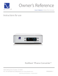
Breakout Box: Below you can see the physical appearance. On the upper left
hand corner is out mentor’s company logo and on the left is SD13 which stands
for senior design 13, our group number. On the front panel of the breakout box a
simple number LCD screen, will be displaying the current channel that it is being
playing on the box.
Dimensions: (W x L x H) -> (8 x 8 x 3) inches
Figure 1: Front Panel of Breakout Box
Figure 2: Back Panel of Breakout Box
Two physical arrow keys will be in close proximity to the display screen which
gives the option to select a new channel by increasing or decrease the audio
channel. Behind the box there will be several inputs and outputs to choose from.
We have an Ethernet port of audio transfer and command transfer. There is also
a XLR option for testing purposes and if the user wants that specific connection,
4
and a simple speaker out connection that is connected to speakers. Below is a
list of specifications that pertain to the breakout box.
•
•
•
•
•
•
•
Mono Class-D Amplifier
Output any one/two channels from Dante
Stereo signal output (Analog, AES-3, S/PDIF)
Compact Size (mount on rear of small speaker)
Channel Selection and Display
Dante enabled device
Breakout Box statues. (ie. amplifier condition)
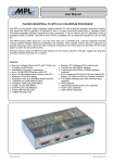
Digital Signal Processing Box
Dimensions: (W x L x H) -> (19 x10 x 3.5) inches
Figure 3: Front Panel of DSP Box
Figure 4 Back Panel of DSP Box
Above you can see the physical appearance , it has the two similar logos of the
breakout box. The DSP box also has a simple display that will be showing the IP
address of the Stellaris chip in order to access the user interface. The knob
directly next to the display is a push button knob. The rotary feature gives the
user the ability to change the numbers of the IP address while the button feature
allows the user to select the number. The “Next” button allows the user to scroll
through the menu to change the IP address, gateway and subnet mask. On the
back of the box there are different ways to import music to the DSP. The main
5
input will be from Ethernet and a computer that is Dante enabled. The XLR
output and input are mainly for testing and consumer purposes. Below is a list of
specification for the digital signal processing box.
•
•
•
•
•
•
•
•
8/16 Processed Channels (Equalization, Dynamics, Reverb)
Dante Audio I/O
Network Control & Monitoring
96 KHz+ Sampling Rate
24-bit Audio Word
Front Panel Controls
2U Size (3.5 inches high and 19 inches wide.)
User interface to control channel selection and monitoring.
3 Research
3.1
Power Supply
For our Senior Design project two separate power supplies were designed in
order to sufficiently power the centralized digital signal processing (DSP) box and
the break out box. Power supplies can be designed in several different ways to
fit the application. For our project, both power supplies need to deliver constant
DC voltage, while the break out box has an additional 90/115 Vac power signal to
oblige the class D amplifier power specifications. The two main power supplies
that provide the DC voltage required is the regulated power supply and the
unregulated (DC) power supply.
3.1.1 Regulated Power –vs- Unregulated
The unregulated power supply, like the regulated voltage supply, uses a
transformer to step-down the voltage and increase the current, but selecting a
transformer for an unregulated power supply is different than selecting one for a
regulated power supply. The output voltage from the transformer needs to be
relatively close to the DC supply voltage that you’re seeking, because once the
signal is rectified and smoothed the output will be a DC voltage. This leads to
the change from an AC signal to that of a DC signal. There are two ways an AC
signal can be altered to DC; the first is by creating a half wave rectifier, but this is
the most inefficient way because the negative signal is lost and only half the
signal becomes positive. The second is by creating a full wave rectifier, this
rectifies the signal entirely and outputs pulsating DC current. At this point,
capacitors resistors and inductors are used to smooth the pulsations. Since
rippling voltage still occurs, we couldn’t use this power supply for our project. In
addition to ripple, an unregulated power supply can vary in the output voltage
because of the fluctuation of load current changes, this can cause failure to some
of the sensitive parts we will be using.
6
This is the way in which we used a regulated power supply. A regulated power
supply foundation is very similar to that of an unregulated power supply in that
first you step-down the voltage, then rectify the signal and lastly smooth the
remaining signal. But a voltage regulator is added to keep the voltage to a
specific value, stabilizing against fluctuations in input voltage and load current.
The regulator also helps reduce the noise and ripple in the output current which
can affect sensitive devices.
Since all designs have drawbacks, the
disadvantage of this is the inefficiency and the heat generated from the linear
regulators.
3.1.2 Switching vs Linear Regulator
There are several types of regulators to take into account when designing a
power supply. The linear regulator is the first voltage regulator you think of when
creating a power supply, it regulates using feedback to determine if the output
voltage is too high. The feedback loop has a built in return, and is completely
stable without external components. The time it takes to regulate the appropriate
voltage is finite, which can be important if a device has a sensitive supply
voltage. What’s impressive about the linear regulator is the amount of noise that
is created is minimal. Since the energy is just burned off there is no electronic
switching, that creates noise. The downfall to the linear regulator is that energy
that is wasted through heat. If the output voltage is too high, the energy that is
retracted is turned into heat; the greater the difference between in input and
regulated voltage the more heat is created. This makes the linear regulator more
inefficient,
The switching regulators on the other hand don’t differentiate the input and
output voltage; it takes energy in small amounts from the input voltage. This is
done by an electrical switch and a duty cycle which regulates the speed at which
energy is transferred to the output. Since the switching regulator only takes
energy when the output voltage drops below the desired amount these regulators
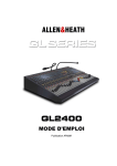
are far more efficient. Below, in Figure 5, you can see a graphical representation
on what a switching regulator is doing. The output voltage Vo is constant while
the input voltage is changing. On the switching state you can see the device
turning on and off allowing energy to keep the output voltage consistent. An
inductor can be placed on the output current to make the output current more
consistent. The downfall to switching regulators is the noise that is created when
the switching states are turning on and off.
7
Figure 5: Switching Regulator Operation
The Transformer that is used for this power supply needs to be close to the
output voltage so the heat dissipated in the linear voltage regulator will be
minimal. Also the power supply needs to create plus and minus twelve volts for.
That’s why a center tapped transformer that outputs 24VAC will be used. This
allows the creation of two 12VAC sin wave in complementary polarity to be
made. Once the sine wave is rectified and filtered regulators will be used. For
the analog section of the power supply, plus and minus 12 V is need, so 7812
and 7912, are linear regulators that will output those respective outputs. The
digital side of the power supply will be a little more complex to design. A voltage
a current selection is more critical due to the sensitivity of some of the supply
voltages and current requirements. The LM2599 family is step-down voltage
switch regulators, capable of driving a 3A load with excellent line an load
regulation. The LM2599 is available in a variety of output voltages including
3.3V, 5V and 12V. Some important features that are included are a low power
standby mode, 150 kHz fixed frequency internal oscillator, and a 4% tolerance on
the output voltage. The 150 KHz internal oscillator allows for smaller sized filter
components.
3.1.3 Supply Noise
Our centralized box contains both analog and digital devices; the mixed signals
created inside this environment could alter the supplied power. All analog
components required the basic components, such as transistors, to work in the
active region. The active and saturation regions can sometimes be milli-volts
apart, which can cause a device not to function properly. “A low noise analog
power-supply network is a stringent requirement for the proper operation of these
components. Noise due to variations in the power supply voltage can be coupled
into the analog portion of the chip and may become amplified along with the
desired signal.” (Actel, 1) This alone could affect the output signal of the Digital
8
Signal Processor; since we will be processing audio signals the resulting
amplified noise would be devastating to the project.
A possible source of noise that could be catastrophic to our project is called
ground bounce, which can cause “the dynamic current drawn from the power
supply leads to frequency-dependent IR (voltage) drops in the VDD and VSS
traces of the printed circuitboard (PCB).” (Actel, 2) Since CMOS technology runs
off dynamic current this could cause all those components to become faulty.
Also during ground bounce, the device ground rises relative to the PCB’s ground
causing corrupted data.
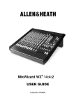
Figure 6: Ground Bounce Primer by Vikas Kumar
To better describe how ground bounce occurs, lets take a look at these images.
To the left, you can see a typical output pin of a device, but in reality a small but
significant inductance exist among the high and low output signal. When A is
turned on, and B is off, the output is high and vice versa for low. With the
addition of the inductor the output voltage changes with respect to current, V = L*
di/dt, where di/dt is related to the rise and fall time of the device. This amount of
current happening rapidly and the small inductive characteristics and the high
and low locations cause a voltage difference to be generated between the PCB
ground and the devices’ ground. Since the sudden impulse of current builds and
dwindles, the ground bounces.
To combat against ground bounce bypass capacitors are used. The image
above shows a shunt bypass capacitor that will remove the ground bounce. The
capacitor compensates for the “moving” ground since the capacitors’ voltage
cannot change instantaneously. With a correct bypass capacitor, the “transient
current, which come into play when a device changes logic state, it won’t have to
flow to and from the power supply, but flow to and from the bypass capacitor.”
(Kumar) Since the accomplice of ground bounce is inductance, the bypass
capacitor should be placed as close as possible to the output device, since
capacitor leads also have an inductance associated with them.
Since ground bounce affects the VCC and ground a large variation could affect
main power bus of the PCB, and alter the performance of some parts, thus it is
important to separate the digital and analog powers supplies as much as
9
possible, to minimize the noise levels. To accomplish this, two different voltage
regulators are used to supply different voltages to the digital and analog
components. The voltage regulator for the digital side must be able to handle the
noise being generated from the digital component and other unexpected noises.
Also an addition of the capacitor between the regulator and device could provide
isolation of power between the analog and digital supplies. “This minimizes the
switching noise produced by the digital electronics from interfacing with the
analog components.” (Actel, 3) Another way to conveniently help with noise
affecting the power supply is to separate the analog VCC and Digital VCC in
different planes and attach the analog and digital ground to the power supply
source. This makes sure that each level is at the same potential. Its also
recommended to have multiple layers to further isolate the power, since Blackfin
can only be mounted on a 6-layer PCB board we will take this into consideration
and allow for the separation.
3.2
Digital Signal Processing
3.2.1 Processor
3.2.1.1
Requirements
In this section, the performance standards and requirements for this system
which are directly related to the digital signal processor are summarized. The
processor was chosen according to these criteria with respect to capability, cost
effectiveness, and accessibility. The specifications include the number of
processed channels, audio sampling rate, audio word size, device dimensions,
network control and monitoring, TDM handling, and matrix routing. Each of these
topics will be briefly described in the following subsections.
24-Bit Audio Words: The bit depth of an audio word determines the resolution
of the signal being sampled, processed, and transmitted. This varies directly with
the signal-to-noise ratio of the output signal and inversely with the amount of
quantization error found in the signal. Quantization error is the result of
truncations of signal values performed when sampling and recording which
compromises the signal integrity as it passes through the system. Thus, a higher
bit depth provides more signal fidelity at the output by reducing this truncation
compared to that of using smaller audio words. A higher signal-to-noise ratio
produces cleaner and smoother audio for the user. Most modern systems
implement a bit depth of 16 bits which results in a signal-to-noise ratio of
approximately 96 decibels whereas studio sound systems require a bit depth of
24 bits producing a signal-to-noise ratio of about 144 decibels [citation needed].
This project is intended for commercial and high-end residential applications so
the bit depth has been selected as 24. It is also notable that more bits support
wider dynamic range, which for the average human ear happens to be around
120 decibels and can reach 140 decibels for some individuals.
10
96 KHz Sampling Rate: In digital audio processing, values for the continuous
analog input signal are sampled and stored at certain intervals determined by the
sampling frequency of the system. By the Nyquist sampling theorem this should
be performed at a minimum of twice the highest frequency of the signal being
sampled, ensuring that enough of the signal is recorded at the input to produce a
faithful reconstruction of it at the output. The continuity of the reproduced signal
increases with sampling frequency since the gaps between samples decrease
and more values can be stored. Increased continuity in audio signals represents
higher quality to the user. The average human ear has a perception bandwidth of
20 Hz to 20 000 Hz with some individuals reaching up to the 23 000 Hz range
[citation needed]. So in compliance with the Nyquist theorem, modern
professional audio systems often sample at a frequency between 44 kHz and
192 kHz [citation needed]. This project aims for 96 kHz sampling which is
generally implemented in studio equipment and since one of the goals is to
deliver high fidelity sound to commercial and residential establishments, such a
requirement is appropriate.
8 Channels of Audio: For this project, it was determined that an appropriate
number of audio channels is 8. For both commercial and residential applications,
a sufficient
1U/2U: Both for commercial and residential applications, a practical and feasible
dimension for this device are either 1U or 2U. The complexity of the processor
influences the size of the device. Given that processors today are moving
towards absorption of peripherals within the die, such technology allows for more
compact designs. Device sleekness carries a large weight in the modern market;
therefore this specification has been established to follow consumers’ needs in
order to emulate the productization constraints aspect of engineering.
TDM Stream Processing: Time division multiplexing is a common protocol for
transmitting audio. So the requirement for the processor is the ability to send and
receive this type of signal encoding in order to interact with other devices and to
be able to exchange audio with them. A processor with a TDM compatible port is
therefore desired so that communications with peripherals can be made possible.
Matrix Routing
In multichannel digital signal processing systems, channels need to be mixed
and routed to various outputs depending on the application. The need to map
different inputs to outputs requires matrix routing abilities in the processor.
3.2.1.2
Part Choice
For the signal processing component of this project, various processors were
considered and researched in order to select the ideal part that corresponds
adequately to the specifications. The Blackfin processor, BF537, by Analog
Devices Incorporated has been determined as most fitting of the signal
processing criteria for this project. This section highlights some of the main
11
features of the Blackfin processor, shows results on three benchmarks and
presents a comparison with similar processors to demonstrate the benefits of this
selection.
BlackFin Main Features: Here are a few outstanding features unique to the
Blackfin family of processors. They come equipped with single-instruction,
multiple-data processor engines that provide excellent and competitive power
efficiency, cost-effectiveness, and efficient memory usage. They are capable of
handling future and concurrent embedded system applications due to the 16 or
32 bit architecture. This architecture also enables the simultaneous handling of
control lines, signal and multimedia processing on just one core. The developer
is given full control of power management in order to tune the performance for
various tasks that the core undertakes. When compared to competing digital
signal processors, the Blackfin family exhibits higher performance and lower
power consumption down to 0.8 V.
The Blackfin processors also include powerful features normally found in
microcontrollers and microprocessors. They have a memory protection unit,
watchdog timer, real-time clock, variable length RISC instructions, UARTs, and
SPI ports. Such versatility allows the Blackfin line to replace other signal
processors, 32-bit RISC MCUs or an ASIC. This family of processors has 16-bit
dual multiply/accumulate architecture with 32-bit registers and 64-bit internal data
paths. The un-core has high-speed memory, peripherals, serial ports, and
parallel peripheral ports. It is capable of moving digital video on and off chip
which indicates a desirable amount of data movement since this design needs to
handle may channels of audio at once. As an initiative to consume less power,
the Blackfin line includes a software-programmable, on chip phase lock loop
which allows control of the clock speeds and the core. The arithmetic operations
on this type of processor are optimized for 16-bit but it is still capable of 32-bit
operations. Also, there is a large amount of bandwidth between the core and the
internal memory since the internal memory is L1 and runs at the core clock rate.
The core supports a sustained two 16-bit multiply/accumulates per cycle
providing 1.2 GMACs at 600 MHz. Besides such computational capabilities, the
Blackfin processors also have a wide voltage operating range.
Benchmark Comparisons with Other DSPs: To evaluate the Blackfin
processors against other processors, three benchmark tests are used: BDTI,
EEMBC, and nbench. These are industry standard benchmarks that are used to
evaluate various aspects of a processor’s performance and functionality which
provide more detailed perspectives than numbers on a specification sheet. More
than one benchmark is used since each one tests a different aspect of the
processor.
BDTI Benchmark Results: The BDTI is a source for processor benchmark
testing and comparison. It is a trusted source for engineering analysis and
advising both to customers and processor designers. The BDTI provides a fact12
based method for communicating processor performance and has a reputation of
credibility as an unbiased source. This benchmark runs various programs on the
processor and produces a document with a full analysis of the results with some
comparisons to other processors. The following is a summary of the document
produced for the Blackfin family of processors.
The execution time results were obtained by running the BDTI LMS Adaptive
Finite Impulse Response Filter benchmark. This consists of an FIR filter, and
error calculation, and a filter coefficient update. This benchmark is short with
setup and housekeeping tasks presenting an importance factor for overall
performance which offer little opportunity for performing parallel operations. The
ADSP-BF533 was chosen to represent the Blackfin line on this benchmark. From
Figure 7 below, it is observed that the BF533 has a faster execution time than
one of the two TI processors chosen as comparisons: TMS320C5509 and
TMS320c6414T. This difference in speed is due to the cycle efficiency of each
processor. The Blackfin processor requires 25% less cycles than the
TMS320C5501 requires. The TMS320C6414T is a high-performance 8-issue
VLIW digital signal processor but it does not take advantage of its parallelism on
this benchmark. The cycle efficiency of the TMS320C6414T is about 20% higher
than that of the Blackfin processor it is compared to.
Figure 7: Execution Time Comparison
The energy efficiency was also tested in this benchmark and the results are
shown in Figure 8. Using the estimated power consumption of a processor and
the benchmark execution time, the energy efficiency is estimated. From the
results on the figure, the processor from the Blackfin family is three times more
energy efficient than the TMS320C5509 and 4 times more than the
TMS320C6414T.
13
Figure 8: Energy Consumption Comparison
Another important metric is the cost-performance metric which is computed by
multiplying the execution time by the cost of the processor. Figure 9shows the
results of this metric compared against two TI processors. The Blackfin
processor is 1.5 times more cost-efficient than the TMS320C5501 and 3 times
more so than the TMS0C6410. The cost of a processor is highly impacted by the
on-chip memory and peripherals and these factors are not considered in the cost
efficiency metric.
Figure 9: Cost Efficiency Comparison
Figure 10 shows the results of comparing memory usage between the Blackfin
line and two other TI digital signal processor lines. Memory usage is important in
determining the system cost of running certain applications. Differences in
instruction widths affect the memory use differences between processors. The
Blackfin line and the TMS320C55x have similar memory usage since their
instruction widths are both 16-bit for this benchmark implementation. The
TMS320C64x has 32-bit instruction widths which increases its memory usage.
14
Figure 10: Memory Usage Comparison
EEMBC Benchmark Results:
The Embedded Microprocessor Benchmark Consortium (EEMBC) is dedicated to
developing software benchmark tests emulating real-world engineering
conditions and environments to properly evaluate the practicality and efficiency of
various embedded systems. Below is Table 1 showing the scores for the EEMBC
benchmark collection of comparisons between the Blackfin BF533 and two ARM
processors. For all of the benchmark tests except one, the Blackfin processor’s
score surpasses that of the ARM processors.
15
Table 1: EEMBC Benchmark Results
nbench Benchmark Results:
The nbench tests are algorithm level benchmarks that are designed to reveal the
abilities of a system’s CPU, FPU, and memory architecture. This program runs
tests on a system and compares it against an Intel Pentium and an AMD K6/233.
On all tests except one, the Blackfin line exhibited superior performance. Table 2
below further demonstrates this.
16
Table 2: nBench Benchmark Results
3.2.1.3
Features
3.2.1.3.1 Programming Method
Overview: The development of the signal processing applications for the ADSPBF537 processor takes place on a PC running a Linux OS. The applications are
compiled with an open source Linux alternative (uClinux) and the image is loaded
onto the board. More about the uClinux distribution can be found in section
3.2.1.4 Real-Time OS.
The Blackfin board selected for this project runs a Linux alternative distribution
kernel which it uses as its control system for running the actual DSP programs.
The programs are developed in a standard PC environment with full compiling
and debugging capabilities. These are then added as part of the uClinux
distribution kernel and compiled within the PC. A standard USB to Serial port and
a Telnet client are used to communicate with the board in order to interact with
and run the applications.
Development Process: The uClinux distribution used for this board supports
application developed in C, C++, and assembly language as does the full Linux
OS. A PC is used to program the digital signal processing algorithms such as
17
parametric equalization, high and low pass filtering, bandpass filtering, and
shelving equations. Such algorithms are developed in C and debugged on the
PC, which is running a Linux OS containing the appropriate C and C++
interpreters. C++ has object oriented features which provide useful data
structuring for handling many channels of audio signals with many parameters
and associated data to process and compute. Some control code is needed also
which is mostly created using assembly language. Control code takes care of
data manipulation such as memory allocation and direct memory access (DMA)
controller interfacing. Also, interrupt functions for the peripheral ports are
developed using assembly language as well as device drivers interfacing.
Kernel Compiling: After program development is complete, certain
modifications need to be made before it is possible to compile the kernel with the
new programs. The compilation process looks to certain configuration files in
order to make appropriate additions to the kernel. The Makefile is updated with
information about the new applications being added to the kernel. This file is
saved to the uClinux distribution directory. The Kconfig file contains instructions
for how to configure the kernel and what applications will comprise the kernel.
This file is also updated with the new programs’ information. In a Linux terminal
window, the configurations are updated and the commands for compiling the
kernel are executed. After this the kernel image is ready for uploading onto the
board.
Kernel Image and Booting: After the kernel image has been created, it is sent
to the board for loading. This is done using a TFTP server and an Ethernet cable
connecting to the developing PC. A server is created in the PC onto which the
kernel image is mounted. An Ethernet cable is then connect from the PC to the
board and a Telnet client is used to communicate with the board via a Serial to
USB port cable. The Telnet used is a program called PuTTY which allows the
user to interface with the board in order to boot the kernel image and run
applications. Through PuTTY, the IP addresses used in the boot arguments for
the board are modified to point to the TFTP server where the kernel image is
saved. The board automatically looks for the image as a file named uImage and
loads this into memory to be run as the board’s OS. This kernel is the control
system used for handling and executing the DSP applications and audio
peripherals interfaces for this project. See section 3.2.1.4 Real-Time OS for more
details on the board’s operating system.
3.2.1.3.2 Ports Available
Serial Peripheral Interface Blackfin’s SPI port is an interface provided for
communicating with multiple SPI compatible peripheral devices. It consists of
four pins: two data transfer pins, one clock signal pin, and one device select pin
for allowing other devices to select the processor. There are seven pins for the
processor to select other devices. This synchronous serial interface supports
master and slave modes and multi-master environments and also supports
18
programmable bit rate and clock phase and polarities. The SPI port can also
send and receive data streams through an integrated DMA controller, though not
simultaneously. The serial data lines of the port can receive and transmit data
simultaneously by serial shifting. The clock line is used to synchronize this
process. This port is mainly a shift register that sends and receives data bits
serially according to the clock line rate. During a typical transfer, data is shifted
serially out of the register while new data is shifted into it. Refer to Figure 11: SPI
Interface Block Diagram below.
Here are some additional features that the SPI port provides:
• Full duplex, synchronous serial interface
• Supports 8- or 16-bit word sizes
• Integrated DMA controller
• Double-buffered transmitter and receiver
• Programmable shift direction of MSB or LSB first
• Interrupt generation on mode fault, overflow, and underflow
• Shadow register to aid debugging
The SPI port can interface with the following SPI compatible devices:
• Other CPUs or microcontrollers
• Codecs
• A/D converters
• D/A converters
• Sample rate converters
• SP/DIF or AES/EBU digital audio transmitters and receivers
• LCD displays
• Shift registers
• FPGAs with SPI emulation
Figure 11: SPI Interface Block Diagram
19
SPORT (Synchronous Serial Port) The ADSP-BF537 features two
synchronous serial ports, SPORTs, which support many different serial data
communication protocols such as Time Division Multiplexing and Stereo Audio
I2S. The SPORTs can operate at up to half of the system clock rate for an
internal or external serial clock. This section will outline some of the main
features of the SPORTs.
The SPORTs have independent transmit and receive functions which provide
greater flexibility in serial communications. The word lengths can be from 3 to 32
bits, configured with either the MSB or LSB first. When interfacing to I2S serial
devices, the SPORT provides alternate framing and control. Both receive and
transmit functions have a data buffer register and a shift register which provides
more time to service the SPORT. The SPORT interface has double the total
supported data streams since each one has two synchronous transmit and two
synchronous receive signals and buffers. It generates serial clock and frame
sync signals at various frequencies and also accepts these signals externally.
Multichannel mode for TDM interfacing is also supported by this port which can
send and receive data selectively from a TDM serial bit stream on 128
contiguous channels from a stream of up to 1024 total channels. Under DMA
master control, this port provides direct memory access transfer to and from
memory. See Figure 12 and Table 3: SPORT Pin Descriptions below for more
information on the SPORT.
Figure 12: SPORTx Block Diagram
20
Table 3: SPORT Pin Descriptions
On the BF537, there are two SPORTs available, SPORT0 and SPORT1. The J
port is used to access SPORT0 and the G port is for SPORT1. The SPORTs can
be programmed for bit rate, frame sync, and word length by writing to memory
mapped registers. Writing to a SPORT’s SPORTx_TX register enables the
SPORT for transmission. The TFS, transmit frame signal, initiates the
transmission of the serial data and each value in the SPORTx_TX register is
transferred to the internal transmit shift register. From here the data is shifted out
starting with either the MSB or the LSB according to the SPORTx_TCR1 register.
The transmission synchronizes each bit transfer with the driving edge of the
TSCLKx which can be configured to either rising or falling. Each SPORT has an
internal receive register for receiving data. The data is written to the SPORT
FIFO register.
Multichannel mode operation of the SPORT offers TDM serial communication.
Each data word of the serial bit stream occupies a separate channel and belongs
to the next consecutive channel. SPORT can easily select words for specific
channels and ignore others. As mentioned, 128 channels are available for
transmitting or receiving, or both simultaneously. The channels selected for the
SPORT are determined by the window offset, window size, and the multichannel
select register. The window size defines the number of channels that can be
enabled or disables by the multichannel select registers. The number of channels
can range between 0 to 15 which corresponds to 8 to 128 channels. The window
offset specifies where to place the start of the active window. The multichannel
frame delay can also be selected to determine the delay between the frame sync
pulse and the first data bit. This value is a 4-bit field in the SPORTx_MCMC2
register and is specifies the number of serial clock cycles of the delay. This
programmable delay allows SPORT to work with different types of interface
devices.
To select channels, there are two types of registers to modify: the
SPORTx_MTCSn and the SPORTx_MRCSn registers. The former corresponds
21
to data transmission channel selection and the latter to data reception channel
selection. Each n register for either receiving or transmitting is 32 bits wide and
there are a total of 4 of these registers. This provides the availability of 128
channels for receiving or transmitting data. Setting any bits in these registers
causes the SPORT to either transmit or receive data through the corresponding
channels. Below is Figure 13 with the multichannel select registers.
Figure 13: Channel Select Registers
Two Wire Interface (TWI) The TWI controller allows interfacing to an inter IC
bus. It is compatible with the I2C bus standard and was designed with high
functionality and compatibility with multi-master/slave bus configurations. The
controller moves 8-bit data while following I2C protocol. The following are
features of the TWI controller:
• Simultaneous master and slave operation on multiple device
systems
• Support for multi-master bus arbitration
• 7-bit addressing
• 100 kbits/second and 400 kbits/second data rates
• General call address support
• Master clock synchronization and support for clock low extension
• Separate multiple-byte receive and transmit FIFOs
• Low interrupt rate
• Individual override control of data and clock lines in the event of
bus lock-up
• Input filter for spike suppression
The TWI controller is basically a shift register that serially transmits and receives
data bits according to the clock rate to and from other TWI devices. There are
two lines in this interface: SDA (serial data line) and SCL (serial clock line). The
SCL is the synchronizing clock that controls the data movement. See Figure 14
below for more information.
22
Figure 14: TWI Interface Block Diagram
The TWI controller follows the I2C transfer protocol with the following basic data
transfer shown in Figure 15:
Figure 15: TWI Transfer Protocol
The controller has reserved names for identifying the bits in the transfer. The 7bit address maps to the bit name MADDR[6:0] and the read/write bit maps to
MDIR. The 8-bit data maps to XMITDATA[7:0] and the start, stop, and
acknowledge bits are mapped to the same bit names in the controller.
3.2.1.4
Real-Time OS
The Blackfin STAMP boards use an open source Linux OS alternative known as
uClinux. The use of the uClinux kernel allows rapid development of applications
since it relieves the developer from having to write the control code by hand. This
is especially helpful when using a powerful processor that will handle large
amounts of data and a more sophisticated control system is required. The
uClinux kernel supports application development in C, C++, and assembly
language which can be created and debugged on an x86 PC with powerful tools
and standard interfacing to devices. These applications can be easily moved to
the uClinux/Blackfin system since the device driver model is identical. Because of
23
this, full attention can be devoted to the creation of applications that are relevant
to the project at hand.
The uClinux kernel is fully debugged with the same tests that many desktop
distributions use before release so this ensures that the kernel is highly robust.
Also, the kernel is designed to encourage code reuse for developers so that
much of the infrastructure need not be designed from scratch. The uClinux API is
identical for all processors that support Linux so code can be easily transferred to
different cores. Only device drivers are required for the proper functionality of an
application after a transfer. The kernel provides excellent hardware abstraction
which allows for the same interface to be used between the application and the
device driver when porting to other processors.
Some limitations of the uClinux kernel include the memory consumption that it
takes to have a stable system is high. Four to eight megabytes of SDRAM are
needed and two megabytes of Flash are needed as well. The boot time is
sometimes 2-3 seconds. Also, some critical kernel operations cannot be
interrupted so interrupts must sometimes be turned off which can cause
unwanted delays. This has been minimized to a reasonable extent but still
presents some effects. The robustness of the kernel may not be bug-proof and
issues may surface when it is tasked with various different applications. Also,
there is much less online documentation and resources available for working with
this kernel distribution and lack of updates on pages and deliverables and a
much smaller community than Linux.
3.2.2 Algorithms
3.2.2.1
Project Requirements
For this centralized DSP system, an obvious requirement is the implementation
of digital signal processing algorithms. This section outlines algorithms
associated with digital signal processing and goes over how they are
implemented in software. Optimization methods are covered as well since large
amounts of signal data will need to be processed at high rates.
Filtering: Various filters are needed as well as parametric equalization. The
filters include high pass, low pass, band pass, and shelving filters. Each of these
fulfills a particular function of audio signal manipulation. High pass filters are also
known as low cut filters. These attenuate the lower frequencies and pass the
higher ones; a process normally used to remove unnecessary and unwanted low
frequencies which surpass the human ear’s bandwidth. It is pointless to waste
power on frequencies that the user cannot hear. Another reason for this is to
prevent damage to speakers due to low frequencies. Opposite of these filters are
the low pass filters which are called high cut filters that attenuate high
frequencies and pass low frequencies. This procedure is often used to remove a
high frequency hiss from audio sound. And again, if most users cannot detect
past a certain frequency, there is not much reason for wasting the power. This
24
applies to systems that merely produce sound for humans to hear, though there
are systems that operate beyond this scope for other detection purposes.
Band pass filters are combinations of high and low pass filters which simply pass
a band of frequencies and attenuates the high and low frequencies past a certain
range. These have similar applications to the ones mentioned above. Shelving
filters are designed to apply an equal gain change to all frequencies beyond a
user-selected shelving frequency, rather than applying a progressive gain
change beyond a cutoff point. Such filters require not only a control for selecting
the shelving frequency, but also one for selecting the amount of cut or boost
applied.
Parametric equalization: Parametric equalizers allow finer and more
sophisticated control of audio than other equalizers. There are three parameters
associated with it: amplitude, center frequency, and bandwidth. The sound
engineer can adjust the amplitude of the gain and can specify which frequency to
focus on as well as the width around this frequency on which to apply the gain.
This type of equalization is normally applied to highly professional audio
applications like sound recording and live sound enhancement. The precision of
parametric equalization allows for targeting and removal of unwanted noise or
feedback in an audio transmitting system and for enhancing and sharpening the
desired portions of an audio signal.
Software Implementation: The different types of filters are defined by gain,
central frequency, mid-point or cut-off frequency, and quality factor. In order to
define these parameters as numerical coefficients, a bilinear transform must be
applied to the analog function in the Laplace domain. These calculations along
with trigonometric and exponential operations cannot be performed in real time
so coefficient tables are often used to bypass this.
25
3.2.2.2
LPF & HPF Methods
Figure 16: Biquad Filter Diagram and Equations
Above is Figure 16 showing the recommended second order recursive filter (IIR)
topology for audio processing applications known as the direct transpose II. To
the right of it are the equations that define its functionality. The top equation is
the transfer function and the bottom is the time domain function. These are the
parameters that distinguish what type of filtering is implemented and what effects
it has on the signal. Recursive filters efficiently achieve a long impulse response
without the hassle of a long convolution. Their performance and flexibility are less
than that of other filters though their execution time is quick. The IIR filter’s
response is composed of decaying exponentials which distinguishes them from
other digital filters that uses convolution.
Low Pass Filtering: Equation 1 shows the parameters associated with low pass
filtering.
Equation 1: Formulas for Calculating the Low Pass Parameters
26
The digital low pass filter is used for DC removal, high frequency noise
suppression, wave shaping, and smoothing.
High pass filtering: Equation 2 shows the parameters used for creating a high
pass filter.
Equation 2: Formulas for Calculating the High Pass Parameters
The digital high pass filter is used for low frequency noise removal (known as
rumble), which may overload the preamp circuit. It is also used for AC coupling at
the inputs of audio amplifiers to make sure the DC current isn’t amplified or it
may harm the amplifier or generate waste heat.
3.2.2.3
Band pass and Shelving
Band Pass: A combination of the low pass and the high pass filter is the band
pass filter. Such a combination can be a band pass or a band reject filter (known
as a notch filter). In many applications, sometimes it becomes necessary to
isolate a specific band of frequencies such as to remove interference in
instrumentation or to separate a specific sound from a signal. The notch filters
are commonly used to reduce the effects of audio feedback on a sound system
with little effect on the frequency spectrum. These are often also used in live
sound reproduction such as public address systems and in instrument amplifiers.
Shelving: Equation 3 shows the parameters associated with shelving filters.
Equation 3: Formulas for the Shelving Parameters
There are low shelf and high shelf filters referred to as bass control and treble
control, respectively. Shelving filters are used to adjust the gain of a signal at
frequencies much lower and much higher than the corner frequencies. This filter
is mainly used for coarse adjustments that enhance the user’s experience rather
than precise equalization. A high shelf filter has no effect on lower frequencies
while applying the gain to the signal at higher frequencies. Low shelf filtering
27
provides gain to the lower frequencies of the signal and does not affect the high
frequencies.
3.2.2.4
Digital Implementation
The Biquad filter featured above in section 3.2.2.2 known as a Direct Form II
Transpose filter, is implemented in software on the Blackfin ADSP-BF537
processor in C language. The processor is designed to optimize the running of C
language code, but in order to do rapid real-time audio signal processing, more
optimization is always welcome. For the Biquad filter above, several coefficients
are calculated in order to create a defined type of filtering for the signal. A
method for minimizing the number of operations need for processing, the
coefficient b0 can be factored out. Figure 17 below demonstrates the resulting
filter topology after this minimization.
Figure 17: Biquad Filter Diagram after Factorization of b0
The new associated parameters after the factorization are as follows in Equation
4.
Equation 4: New b1 and b2 values
This factoring is helpful when using cascaded filters since the b0 coefficient can
then be pre-calculated for all the cascaded filters once.
3.2.3 Analog to Digital Converters (ADC)
3.2.3.1
Requirements
Analog to digital converters are electronic device that take a continuous analog
signal and converts its amplitude to a digital binary representation. For our
project we will be using a 24 bit ADC which as the ability to convert the analog
signal into a digital signal with 16777216 levels or 224. Below is an image
portraying how an analog signal getting transformed into a digital signal. The
more levels or bit resolution an ADC has the more accurate the analog signal will
be converted into digital. The digital signal is represented in different voltage
28
levels, the smaller the voltage difference the higher the bit resolution. The
equation to determine the different voltage levels is = (voltage range) / (bit
resolution).
Earlier it was explain how the amplitude was converted to a binary value, below
explains how the time information is represented after an ADC. The analog
signal is uninterrupted in time and it is required to translate this to a stream of
binary digital values. For this a sampling rate needs to be determined, the higher
the sampling rate, the more values per second the information is collected and
the more accurate the analog signal will be represented. The Shannon-Nyquist
sampling theorem sates that the sampling rate must be at least twice the highest
frequency of the incoming signal. The general accepted standard range of audio
frequencies is 20 to 20000 Hz; therefore a sampling of 192 KHz is at least twice
the greatest incoming frequencies. ADCs cannot instantaneous convert the
signal so a low conversion time is required in an ADC. The conversion time in an
ADC is the amount of time the incoming signal must be constant for the correct
transformation to be performed. Most ADCs have a sample and hold circuit
which uses a capacitor to store the analog voltage at the input and an electronic
switch to disconnect the capacitor from the input. For our project we are using a
2ch ADC or 4 channel depending on the selected input.
3.2.3.2
Part Choice
PCM 4222 - The PCM4222 is a high-performance, two channel analog to digital
controllers with a bit resolution of up to 24-bit linear pulse code modulation and a
sampling rate of 216 kHz. The PCM4222 also has a 1-bit Direct Stream Digital
(DSD) which is a way to encode an analog signal to digital. This particular ADC
has a six bit modulator outputs which gives us the ability to design digital
decimation filters and processing hardware (Blackfin). With the PCM 42222 the
designer has the ability to choose the sampling rate between 8 and 216 kHz,
along with the capability to support 64x or 128x DSD outputs all with selecting
the correct control pins.
This analog to digital converter is a two-channel, multi-bit modulating high
resolution analog signals to lower-resolution digital signals. The converting is
done by using differential amplifiers as feedback of the two signals to improve the
conversion. The analog signals are sent through left and right channels which
each have a pair of differential voltage input pins. The left channel input pins are
located at 10 ( VINL-) and pin 11 (VINL+), pin 10 if for the inverting signal, while
pin 11 is for the non inverted signal. The right channel also has 2 pin the
inverting signal pin is located at 1 (VINR-), while the non inverting pin is located
at pin 3 (VINR+). Each input pin has a nominal full scale input of 2.8 Vpp. A
master clock is required for the operation of the internal logic and modulator
circuitry. The master clock is supplied form an external source, connected to pin
35 labeled MCKl. This ADC can be put on a standby state by setting and holding
29
the reset input pin (pin 36) for the duration of the standby span. Minimum power
is consumed during this sate when all clock inputs for the PCM4222 are low.
The PCM 4222 analog to digital converter has 48 pin locations. The value of the
48 pins will determine the operating characteristics of the analog to digital
controller. Some important pins that control the audio interfacing are pin number
43 (FMT1) and pin 44 (FMT0). These pins determine the audio out format, the
options for the output is left-justified, I2S, TDM and TDM with data delayed one
BCK cycle from LRCK rising edge. Below the Audio Interface table show the
values needed to achieve the desired interface. We are keeping our audio
interfacing consistent through the project; therefore we are using the TDM
feature off this analog to digital controller. The audio data will be split up into 4
frames. Each left and right channel time slot is 32-bits long, with 24-bit data LeftJustifies in the time slot. Audio is most significant bit first. The sub-frame
assignments for each PCM4222 device are selected by the corresponding SUB0
(pin 25) and SUB 1 (pin 26).
FM1 (pin 43)
0
0
1
1
FMT0 (pin 44)
0
1
0
1
Audio DATA Format
Left-Justified
I2S
TDM
TDM with data delayed one BCK cycle
from LRCK rising edge
Table 4: Audio Interface
The sampling mode can be determined by pin number 20 (FS1) and pin 19
(FS0).There are three sampling modes to –choose from; normal sampling rate
between 8 kHz and 54 kHz, double speed sampling 54 kHz through 108 kHz and
Quad speed sampling mode which is between 108 kHz and 216 kHz. We will be
using a sampling rate of 192 kHz, so for this pin 20 is HI and pin 19 is LO. For
TDM formats, the sampling rate will determine the number of channels carried by
the TDM. Normal mode can carry eight channels, double rate can carry four
channels and quad rate mode can carry two channels. When using TDM formats
Quad speed sampling, it is recommended that both the SUB0 and SUB 1 pins be
forced low.
•
•
•
•
•
•
•
PCM 4222 Key Features.
Sampling Rates from 8 kHz to 216 kHz
340mW Power Dissipation for 96 kHz sampling rate
2-Channel, multi-bit delta sigma converter.
24-bit word length, with a dynamic range of 123 dB
Differentiates signal inputs for better conversions.
Overflow indicators for both channels
Supports TDM, I2S and Left-Justified audio data formatting
30
PCM 4204 - The PCM 4204 is a high-performance digital to analog converter that
was designed to be used in the professional audio field; this ADC can convert
four channels of analog audio to digital audio. The PCM 4204 ADC feature 24-bit
linear pulse-code modulation data outputs, along with a bit for Direct Stream
Digital data output and input capability for all four channels, along with a
sampling rate of up to 216 kHz. A five volt power supply is required for the
analog portion of the device while a 3.3 volt power supply is required for the
digital circuitry.
This analog to digital converter unlike the PCM 4222 has four channels instead of
two channels. Each of the four channels has a pair of differential voltage input
pins. The inverted first channel is located in pin 1 (Vin1-) while the non-inverted
signal is sent to pin 2 (VIN1+). The VIN2- (pin 58) and VIN2+ (pin 59)
correspond to channel two inverted and non-inverted signal respectively.
Channel three pins are located at 54 (VIN3-) and 55(VIN+) and channel four is
located at 47 (VIN-) and 48 (VIN+). Each analog input pair can have maximum
amplitude of 6 VPP differentials. Schottky diodes are recommended for the VCC
inputs located at pin location five and forty four because the analog input voltage
cannot swing below ground or above VCC by 300mV.
The PCM 4204 can operate in several modes, in can operate in three pulse-code
modulation sampling modes of single rate, dual rate or quad rate, it can also
operate in two direct stream digital output rates. PCM single rate mode samples
data up to 54 kHz using a delta-sigma modulator. The dual rate samples data at
54 kHz to 108 kHz and the quad rate samples frequencies between 108 kHz and
216 kHz. Quad rate mode can either be run in master mode operation and slave
mode operation. We will be using Quad mode in slave mode because TDM is
only applicable in slave mode. Therefore to access Quad mode in slave mode
FS2 (pin 14) is LO, FS1 (pin 13) is HI and FS0 (pin 12) is LO.
This analog to digital converter supports 24-bit linear PCM output, as well as
DSD. In this project, the audio format will stay consistent; therefore time division
multiplexing will be used. Time division multiplexing is only available in Slave
Mode. The S/M’ (pin 17), FMT0 (pin18), FMT1 (pin19), FMT2 (pin20) inputs are
utilized to select either slave or master mode and the corresponding audio data
formats. In Slave mode, the pulse-code modulation bit and left/right word clocks
are configured as incoming pins. In Slave mode DSD is not supported instead
common PCM audio data formats such as TDM, I2S, 24-bit right justified, and 24bit left justified are available. Below is a table illustrating the inputs required for
the S/M, FMT0, FMT1, and FMT2 to achieve an audio data format.
31
S/M’
FMT2
FMT1
FMT0
Audio Data Format
0
0
0
0
24-bit Left-Justified
0
0
0
1
24-bit I2S
0
0
0
0
0
0
0
0
1
1
1
1
1
1
0
0
1
1
0
1
0
1
0
1
24-bit Right-Justified
TDM with no BCK delay for start of frame
TDM with one BCK delay for start of frame
Reserved
Reserved
Reserved
Table 5: Master Mode Audio Data Format Selection
TDM can be sent in long frames and short frames. Long frame only support
sampling frequencies below 108 kHz, therefore we will be using short frame TDM
data format. The length and rate of the TDM frame is auto-detected by the audio
serial port. SDOUT1 carried data for all our channels when using TDM data
formats while SDOUT2 is forced low. The SUB pin is only used when Long
Frame TDM is used, since we will be using short frame TDM operations the SUB
pin is ignored, but hardwiring the SUB pin low is acceptable.
•
•
•
•
•
•
PCM 4204 Key Features
Sampling Rates up to 216 kHz
4-Channel delta sigma converter
24-bit PCM audio data format
Supports TDM, I2S, Left-Justified, and Right-Justified.
Dynamic range of 118 dB
615 mW Power consumption at 192 kHz
3.2.3.3
CODEC
After a meeting with our mentor, he brought up the idea of using a codec chip
which is a device that can decode a digital signal. This chip will simplify our
system because we will be reducing the number of pins by removing some
devices. A codec and digital receiver will replace a multiplexer, digital interface
transceiver, ADC and DAC. Simply put a codec has a built in analog to digital
decoder along with multiplexers and digital to analog converters. After some
initial research we were able to find a codec that fit the design specification of the
project.
CS 42436 - The CS42436 codec by Cirrus was designed for home theaters and
automotive audio systems to encode high quality multichannel audio. This
current codec has six 24-bit resolution analog to digital converters along with six
24-bit resolution digital to analog converters. With this codec balance or
unbalanced signals can be inputted or outputted. Other functions that the codec
can do include autonomous digital volume controls for each individual DAC,
32
digital de-emphasis filters for the DAC, digital volume control with gain on each
ADC channel. The serial audio port allows up to six DAC channels and eight
ADC channels in a Time-Division Multiplexed interface format. The CS42436
has three sampling modes. Single-speed mode, double speed mode and quad
speed mode. Single speed mode supports sampling rates up to 50 kHz, while
double speed mode supports input sampling rates up to 100 kHz. Quad-Speed
mode supports rates up to 200 Khz and this mode is only available in software
mode.
The CS42436 can be operated in two different modes, software mode and
hardware mode. Software mode gives the designer the ability for the codec to be
hooked up to a separate MCU and DSP, so we will be using this codec in
software mode. TDM will be used to interface the audio signal between the ADC
and DSP unit. For the codec, TDM is only supported with sampling frequencies
below 100 kHz, therefore we will be using that sampling frequency. The ADC and
DAC serial ports operate as a slave on support the TDM digital interface formats
with bit depths between 16 and 32 bits. Data clocked out of the ADC on the
falling edge of SCLK and clocked into the DAC on the rising edge. The SCLK
clock must operate at 256*Fs where Fs is the sampling rate. Below is a
representation on how TDM is sent on the clock intervals. The TDM data is
received most significant bit first, on the second rising edge of the SCLK
occurring after a FS rising edge, all data is available at on the rising edge.
Figure 18: TDM Serial audio Format
In software mode the CS42436 can be run in SPI mode, the Stellaris is able to
send commands and receive information from the codec. CCLK is the control
port bit clock and CDIN is the input data line from the microcontroller, and
CDOUT is the output data line to the microcontroller. Data is clocked on the
rising edge of the CCLK and out on the falling edge. I2C is used to communicate
between the codec and Stellaris, data sent and received depending on the SCL
clock. Below are timing diagrams for a read/write cycle. A start condition is
defined as a falling transition of SDA while the clock is high, while the stop
condition is a high, the entire transition occurs while SDA is low. The first seven
byte sent consist of the chip address field and a read/write bit, high for read and
low for write. The upper five bits of the seven bit address field is fixed at
10010XXD. The “XX” are the settings of the AD1 and AD0, the remaining “D” bit
is the read/write bit. If the “D” bit is write, the next byte is the memory address
33
pointer which selects the register to read or write to. If the operation is read, the
contents located at the supplied MAP address will be sent back.
Figure 19: Timing: I2C Writing
Figure 20: Timing: I2C Reading
Each Digital to analog converter output level is controlled via the volume control
registers operating over the range of 0 dB to -127.5 db. The volume can be
adjusted in increment of .5 dB at the rate controlled by the SZC bits in the digital
volume control register.
•
•
•
•
•
•
•
Key Features CS42436
Six 24-bit resolution audio to digital converters
Six 24-bit resolution digital to analog converters
DAC sampling rate of 192 kHz
ADC sampling rate of 96 kHz
Software mode allows communication to microcontroller by ways of SPI or
I2C.
Time Division Multiplexing serial interface
Simplifies Hardware connection by reducing the number of pins and
combining ADC, DAC, and MUX.
3.3
Microprocessors
3.3.1 Project Requirements
3.3.1.1
DSP Box
The microprocessor is responsible for everything besides audio processing. As
noted above, all audio processing is taken care of by the very capable digital
signal processor. A processor should be chose for these features: the availability
of great development tools, ease of display interfacing, on-board Ethernet stack,
and the large array of available interface formats (I2C, CAN, SPI, etc). The
34
microprocessor also interfaces with the Dante Brooklyn-II module to set channel
selections, to retrieve channel names, and to check system status bits.
Ethernet Control: The microprocessor interfacing with Ethernet is essential to
the success of the project. The Dante Brooklyn-II chip requires packets from an
Ethernet based network. An Ethernet stack is also required for a web server to
run. A nice API for controlling hardware settings based on web server
interactions is required. This easily enables hardware level control from a webbrowser user interface. The Ethernet-Hardware API will talk directly to the
microprocessor/DSP API, giving the website the ability to change equalizer,
dynamics, routing, and reverb settings as well as monitor the status of all
channels. The Ethernet stack will also enable the unit to receive TCP packets
from breakout boxes with their status. It is also possible to change the address
of each breakout box from the web interface associated with the centralized DSP
unit. The microprocessor is able to send and receive Ethernet through a gigabit
switch IC.
Web Server: The availability and accessibility of a web server on the
microcontroller really opens a lot of possibilities. Instead of the centralized DSP
unit only being physically accessible via an LCD screen and a few rotary
encoders, it will always be available on a network and possibly even on the
World Wide Web. The loss of on-site monitoring and maintenance requirements
means that the installation costs the owner less money or time. It also greatly
increases the owners, as well as the maintainers, ability to centrally monitor and
control the entire system. The web server is capable of serving the status of
every breakout box on the same local area network (LAN). It also gives the user
the ability to change the routing matrix. In addition, the user is able to change
the settings of equalizers, dynamics, and reverb processing for every input and
output channel. There are several options for web server and TCP/IP support on
the Stellaris. The two main free TCP/IP Ethernet stacks are microIP (uIP) and
lightweight IP (lwIP). Both stacks are freely distributable under open-source
licensing.
Dante Interfacing: The Dante digital audio standard over Ethernet is entering
the centralized DSP unit through Audinate’s Brooklyn-II module. The Brooklyn-II
module outputs TDM audio over eight wires and is wired up to a port on the DSP.
The Brooklyn-II module also has control lines. These control lines will be
connected to the microprocessor. The control lines allow the reading of channel
names, the setting of the TDM output formats, the selection of output channels,
and the re-encoding of TDM audio onto Ethernet.
User Interface I/O: The microprocessor is handling all of the user interface
inputs and outputs. A single rotary encoder that is wired up to GPIO inputs on
the microprocessor is utilized to sort through large lists of available options, such
as letters of the alphabet. The rotary encoder has a push-button in it. That
button is wired up active-low so that when the button is pressed there is a
35
sudden drop to ground on the pin. This push-button advances the character that
the rotary encoder is modifying on the screen. The microprocessor will also
monitor a second push-button, the “back” button. The back button returns the
entire screen to the last screen viewed.
3.3.1.2
Breakout Box
In the breakout boxes there is a microcontroller to control various parts. These
parts include a user interface consisting of a LCD screen and three buttons for
selecting and scrolling, a codec used for digital to analog conversions, analog to
digital conversions, multiplexing and volume control, interface with a temperature
sensor and the Dante Brooklyn-II device. Even though most microcontrollers are
have built in ADCs and DACs we are using separate ADCs and DACS since the
project remains on a level for professional audio fidelity. The microcontroller is
able to select which codec path our incoming audio signal should travel whether
its to the a DAC then to the amplifier or to pre tab cables like XLR or SPIDF. Itis
also able to receive, from the Dante Brooklyn-II device, like selected channel and
other channels that can be selected and possible volume level. Once the
channel information is received it is displayed through a LCD screen where the
user is able to select which channel wished to be amplified. The microcontroller
is also in control of the interfacing with the temperature sensor and the Class D
amplifier. The microcontroller is able to use the information from these two
components in two ways. It takes a reading from the temperature sensor of the
Class D amplifier and display this to the users on the breakout box or send it
back the DSP box, through the Dante Brooklyn-II device, where the temperature
can be viewed. It uses the status pin on the Class D amplifier to confirm that the
amplifier is still working. When the status pin becomes high the microcontroller
will have to report back to the DSP box that there has been a failure of the Class
D amplifier.
A microcontroller was chosen for these tasks instead of a microprocessor for
various reasons. A microprocessor is a similar to a microcontroller differs from it
by the usage and design. A microprocessor is used for general use such as
personal computers or in other application with heavy processing is need over
various pathways. Microcontrollers are used mostly in imbedded system with
real-time applications where a few set tasks are needed to be performed over
and over again with high precision. Most microprocessors need external memory
and other peripherals to complete its computing tasking causing the system to
quite costly for reproduction purposes, while microcontrollers have all their
memory and peripherals imbedded in the chip and ready to be programmed for
their specific tasks. A microprocessor would have been used if the breakout box
had to do so dynamic processing like in the DSP box but the breakout box will
only be routing and selecting the audio channel and reporting any errors back to
the DSP box. Using a microcontroller is perfect for the application of a breakout
box because of the number of units that would be required in a distributed audio
36
system. Also, the breakout box is performing a set of very simple task that are
predetermined.
Microcontroller Requirements
I/O pins for connecting to a codec, temperature sensor, amplifier and the
user interface
Needs to have Ethernet capabilities
Be able to interface with Dante Brooklyn-II
large enough memory for completing the tasks designated
I2C and SPI capable
3.3.2 Part Choice
3.3.2.1
DSP Box
The Stellaris microprocessor is responsible for everything besides audio
processing. As noted above, all audio processing is taken care of by the very
capable Blackfin digital signal processor. The Stellaris microprocessor was
chosen for several reasons. The reasons include, but are not limited to: the
availability of great development tools, ease of display interfacing, on-board
Ethernet stack, and the large array of available interface formats (I2C, CAN, SPI,
etc). The Stellaris chip is interfaced with the Dante Brooklyn-II module to set
channel selections, to retrieve channel names, and to check system status bits.
The sheer amount of existing documentation and sample programs means that
programming Stellaris should not be impossible!
3.3.2.2
Breakout Box
After the deciding on a microcontroller over a microprocessor a specific micro
controller need to be chosen. There were two major considerations for the
microcontroller in the breakout box. The two considerations were the MSP430
and the stellaris.
MSP430 family had a vast assortment of different microcontrollers to choose
from. So this microcontroller seemed to be a good choice for the breakout box.
Some of the features for the MSP430F22x series consisted of the following.
Low supply range 1.8V to 3.6V
Ultra-Fast Wake-up from standby mode
Universal Serial Communication Interfaces
◦ UART
◦ I2C and SPI capable
A wide range of flash memory ranging from 8KB to 32KB
The stellaris was another viable option for the breakout box microcontroller. This
had more features but at an increase of price. Some of the features for the
stellaris LM3S8962 are as follows.
36 interrupts with eight priority levels
37
256KB internal flash memory
5 – 42 General Peripheral I/O (configuration dependent)
Communication Interfaces
◦ UART
◦ I2C and SSI capable
◦ CAN and Ethernet capable
From these two the MSP430 it was initially thought to use for the breakout box.
After, researching into the two products it was decided that the microcontroller
needs to have a standard for Ethernet and that using the same microcontroller in
both DSP box and breakout box would be ideal and less complicating for the
overall design if the project was ever massed produced. Not to mention the vast
improvement in features and peripherals.
3.4
Audio Transfer Methods and Protocols
3.4.1 Balancing Audio Signal
Noise can be aided by several benefactors; the random fluctuation of electrical
signals and electromagnet interferences from any device creates noise. This
noise can be detrimental to a bit signal or even worse an audio signal. A main
specification of this project was to create high quality audio as if Beethoven’s’
sixteenth string quartet was playing in front of you; this is why creating a balance
audio signal is so imperative to this project. A balance interconnection is the first
step in creating a noise free signal, balanced connections use impedance
balanced lines to cancel out external noise. A balanced line driver creates a
balanced signal from an unbalanced signal; the balanced signal simplifies the
noise cancellation process. An impedance–balanced line allows the signal to
travel through electrical wires which are identical, thus picking up the same noise
interference.
To create an impedance-balanced line two identical wires are twisted together
and then enclosed with a conductor that works as a shield. The single conductor
configuration unlike the unbalanced two-conductor arrangement allows for noise
protection along with ground loop prevention. Ground loops occurs when
unwanted current in a conductor creates a different potentials at the two
connecting points, this creates an obscene amount of noise and interference in
an audio system. So to eliminate this one conductor enclosing the wired is used.
The purpose of the twisting wires was produced from statistical knowledge, if the
wires are intertwined like a DNA strand, then they have the same statistical
chance of picking up some unwanted noise from electromagnetic inductance.
“The resulting signal appearing equally on both wires is known as a Common
Mode Signal, and how well it is rejected by the audio circuitry is known as the
Common Mode Rejection Ratio or CMRR.” (Blyth). In a XLR connector each wire
is carrying the same signal but in different polarities, so one signal is the inverse
of the other. Once these signals are sent through a difference amplifier, noise
38
that is identical on both wires (because of the spiraling wires) is subtracted out
and the remaining signal is noiseless. Some benefits that come from sending a
balanced differential signal through XLR is the wires are spiraled so the
electromagnetic field around the line, in theory, is zero. In addition the signal
level is doubled due to the subtraction of the inverted signal with the original.
Below, Figure 21 you can see the amplification of the signal along with the
cancelation of the noise that was imposed by arbitrary outside sources. Another
positive feature of XLR cable is the physical locking mechanism that make for a
secure line transfer between the signal driver and receiver.
Figure 21 Balanced Signal
3.4.2 Part Choice
DRV134 (Line Driver): To create the signal we talked about above, we used the
Audio Balanced Line Driver (DRV134) by Texas Instruments. The DRV134
contains differential amplifiers that convert a single-ended input to a floating
balanced output with a gain of +6dB. Other features that are included is a slew
rate of 15V per micro sec and settling time of 2.5 micro second to .01% of the
correct value. A high slew rate and fast settling time are important when sending
a signal, because the faster the slew rate and settling time, the more accurate
the outgoing signal will be to the original signal. Inside the DRV 134 there are
three op amps, the input signal is inverted and sent to two cross-coupled
differential amplifiers that will create the balanced outputs. The resistors inside
this devise are laser trimmed from thin film resistors, this guarantees outstanding
output common-mode rejection and signal balance ratios. From earlier research,
ground bounce was found to have a great effect on the power supply and PCB
board ground. So to combat this, 2 capacitors are to be placed on each of the
supply voltage terminals (V+ and V-). A recommendation from the data sheet
states that non polarized electrolytic capacitors should be placed on the output
signal terminals.
The creation of this balanced line driver could of bin made by hand, but the
precision obtained by using the DRV134 could have never been matched. The
laser trimmed harmonized resistors present optimum output common-mode
rejection. The discrete precision resistors, which are offered, wouldn’t be made
close enough to accomplish this. Also if this was to be hand made three op39
amps would need to be used, each needing supply voltages and connecting
wires to each op amp. Each op amp would require anywhere from 5 volts to 12
volts, while the DRV134 supply voltage can be anywhere from 4.5 volts to 18.
Since our power supply will be creating plus and minus 12 volts the DRV134
works out perfectly. An increase of exposed circuits and resistors could impose
more noise into our balance drivers, which is ironic since the reason line drivers
are used is to terminate noise. This does simplify our project in many ways, for
testing purposes and troubleshooting purposes.
These balanced line drivers are related to this project in more ways than one.
They were used to test the audio signal from the Blackfin processor located in
the centralized DSP box, and be used in our break out box after the class D
amplifier. Since we are using a technology we have no prior knowledge of,
Dante, we wanted to make sure Blackfin is correctly processing the audio
information and sending it out correctly. The DRV134 balanced audio drivers
were used for this, they send audio to a separate receiver that plays high quality
audio. Dante, in the final product, sends music through Ethernet which is
received at our break out box.
In the breakout box, the audio through the
Brooklyn device is sent through our class D amplifier, and then sent to a pair of
DRV134 to become balanced. We have the ability to send 2 channels to the
breakout box therefore a pair of line drivers are needed to accomplish this. The
internals of the INA137 and the DRV134 are shown below in Figure 22.
Figure 22: Internal Schematic of INA137 and DRV134
INA 137 (Line Receiver): The INA137 line receivers were designed to work
directly with the DRV134. They contain high performance op amps with on-chip
precision resistors. The resistors are laser trimmed for accurate gain and optimal
common –mode rejection. Similarly to the DRV134, these line receivers are a
wide supply voltage, low distortion and high slew rate. The INA134 has the
ability to have a gain of two or a half; also these line drivers can be on an eight
pin single line receiver or fourteen pin double line receiver. Above you can see
the schematic of the line receiver. The creation of this line receiver could of bin
made by hand, but the precision obtained by using the INA137could have never
40
been matched. The laser trimmed harmonized resistors present optimum output
common-mode rejection. The discrete precision resistors, which are offered,
wouldn’t be made close enough to accomplish this. This would be used on the
actual speaker to receive the audio signal.
3.4.3 Audio over Ethernet
The audio industry is growing rapidly; every electrical consumer product is
growing towards the digital technology. For example televisions, no new
television set is being sold today if it its hi-definition compatible or 3D compatible.
We live in an age that demands the best visual and audio experience. Audio
over Ethernet is a fairly new technology that offers high fidelity, low latency audio.
For you non audiophiles out there high-fidelity and low latency is an exciting
requirement to have in any home/commercial audio system. High-fidelity refers
to the high-quality reproduction of sound, to distinguish it from other inferior
equipment. High Fidelity equipment has a minimal quantity of noise and
misrepresentation and a precise frequency response. Latency accredits to a
short period of hindrance between when audio signal enters and when it
emerges from an audio system. Latency can be affected by long wires,
buffering, digital signal processing, digital-to-analog converters and analog-todigital converters. Ethernet has the ability to transfer Gigabits of data through
Ethernet frames or data packets, Ethernet frames are sent through Ethernet with
IEEE 802.3 standard. Below, in Figure 23: Ethernet Data Standard you can see
an illustration on how data is sent. The first 56-bits are the preamble, which
allows devices on the network to easily detect a new incoming frame. The Start
of Frame Delimiter (SOF) is an 8-bit value marking the end of the preamble of an
Ethernet frame, which signifies the start of the real frame. Next following the
SOF is the destination address or MAC destination. This is the physical
destination address where the data is sent. Immediately following the destination
address is a 6 byte source address, which has the physical address where the
data is coming from. The next two bytes is the Ethertype, which indicates which
protocol is encapsulated in the data. There are thirty-eight different Ethertype
protocols to choose from. After the Ethertype, next is the data, this can hold 46
to 1500 bytes of data and lastly is the Frame Check Sequence (FCS). The
Frame Check Sequence, which consists of 4 bytes, is used for extra checksum
characters added to the frame for error detection and correction.
Ethernet is the next great advance in the audio world. It does much more than
improving the sound quality and latency, it simplifies installation and
troubleshooting. With Ethernet you have the ability to send multiple channels
through one CAT5 Ethernet cord. With Dante, a bi-directional 16, 32 or 64
channel system can be made. This can dramatically reduce the man hours and
complex wiring of a 16 plus channel system and less wires mean troubleshooting
is straightforward. If an Ethernet network already exist for example in a museum
or bar, an audio over Ethernet system can be functional in a matter of minutes.
41
This simple setup and troubleshooting along with high fidelity and low latency is
the reason audio over Ethernet will be the new source of professional audio.
Figure 23: Ethernet Data Standard
3.4.3.1
DSP Box
Dante Brooklyn II module is used in the digital signal processing box to send
music to the breakout box and to receive music. For a Brooklyn II module to
receive music the transmitter need to be a Dante enabled devise. Audinate, the
creator of Dante, has created software called virtual soundcard which turns a
personal computer or Mac into a Dante-enabled device. This software allows the
computer to record or play out through the standard Ethernet port on the
computer and process audio to and from a network with other Dante devices.
Dante will be sending a 2, 4, 8, or 16 channels of TDM audio signal to our digital
signal processor, Blackfin. The Dante Brooklyn II module also has control lines
which are connected to the Stellaris microprocessor. The control lines send
channel information like channel labels and which box is receiving which
channel. Dante doesn’t need a dedicated network therefore audio and control
can be sent through the same Ethernet cable.
3.4.3.2
Breakout Box
The breakout box is Dante enabled; the breakout box automatically finds and
configures its settings with the DSP box, making it a “plug and play” function.
The Brooklyn II module delivers both audio signal and control signals over the
same Ethernet cable. The User Interface is able to send control and data signal
to the Stellaris in the MCU. For this to happen and user interface is able to
communicate with a Stellaris chip, by IP address, on the DSP box. The audio is
processed in the Blackfin then sent out to the breakout box along with control
information. When the information reaches the Brooklyn II module, the control
42
information is sent to the Stellaris in the breakout box. This determines which
audio signal is played at the breakout box, and the stellaris sends a signal to
Brooklyn II to play the correct channel. Each channel can be changed to a name
which makes it easier to locate the breakout of if one were to stop working.
Another feature that the Brooklyn II module will help out with is a thermal reading
on the audio amplifier. If the class D amplifier is overheating or quick working, a
signal is sent back to the user interface letting the user know of the problem.
3.4.4
Dante
Dante was designed to make professional audio networking easily accessible for
audiophiles. Dante creates the ability to manage a network and makes plug and
play networking possible. A Dante system can send data from 100 Mbps to
1Gbps making it a modern high speed performance digital media transport
system that runs over standard IP networks. Dante is a powerful technology that
allows many channels of audio to be transmitted and received over a single
Ethernet cable. Dante enabled devises have the ability to discover one another
over the network and learn each other’s capabilities such as sample rates and bit
depth.
With Dante, each channel can be given a name that corresponds with its location
or audio type, which makes troubleshooting effortless. Dante has the ability to
send a maximum channel depth of 1024 or 512x512 bidirectional channels.
Dante’s synchronizes local clocks in each networked device connects with a
master clock with very high accuracy. This clock harmonization is completely
autonomous of the audio data and the sample rates being executed on the
network, which gives the ability to process the incoming or outgoing audio data
quickly without waiting. The local clock is used to time stamp network packets, to
control the rate at which audio sample are transmitted and received.
In addition to audio and video signal transfer, Dante can send device control and
configuration signals.
Equipment-specific messages and application
programming interfaces (APIs) for controlling signals and labels can be sent and
received across the Dante IP network. Dante has several competitors including
CobraNet and EtherSound, reading online these competitors don’t have the easy
“plug and play” feature that Dante offers. Our sponsor Alcorn McBride has some
experience with this unit, to take advantage of that we have decided to use
Dante’s’ Brooklyn II module.
43
•
•
•
•
•
•
•
•
•
Dante Quick Overview
Dante gives a cost reduction of cabling, switching and routing by using
standard Ethernet/IP media and hardware.
Network Latency is reduced to hardly noticeable levels
Reduction of cost and complex system wiring since transmission of audio
and control data can be sent through the same configured network.
Sends professional audio quality by enabling lossless digital audio
transportation. This eliminates redundant conversions between analog
and digital converters.
Ability to have Dante enabled devices working together and configure bit
depths and sample rates.
Prior existing infrastructures that are compatible using standard
Ethernet/IP networking can easily implement this technology.
The signal routing is independent of network layout; this enables devices
to remember audio channel labels and routes.
Versatile sampling rates of 48, 96, and 96 kHz.
Versatile bit depth of 16, 24, and 32 bits
3.4.5 Brooklyn II Module
Due to a non-disclosure agreement some aspects of the Brooklyn II module
cannot be discussed in this paper. Dante Brooklyn II module is a mini-PCI form
factor component that provides a complete, ready to use Dante interface for a
network audio product. The Brooklyn II module can do typical Dante features
such as automatic device detection and system configuration, making network
setup simple. This module can also send low latency synchronized transport of
uncompressed audio over IP networks at high speeds. Brooklyn II has the ability
to send up to 64 X 64 audio channels at different sampling rates.
This project consists of two separate boxes one designated for digital signal
processing and user interaction, and the other for channel selection and audio
amplification to break out speakers. One of the common applications for this
module is to provide an audio and data link for breakout boxes. The Brooklyn II
supports all the core networking and control functions needed for product like
DSP processors, amplifiers and breakout break in boxes, the Brooklyn II also has
a microprocessor. The power supply for the module is 3.3 volts with a power
consumption of less than 2 watts, pin locations and descriptions cannot be given.
The Brooklyn II can be connected to an Ethernet network in several ways: a
single Ethernet port, two redundant network ports through an Ethernet switch or
lastly by two or more non-redundant network ports through an integrated
Ethernet switch. Only one switch port is required for connection to the module,
products can use additional switch ports to support daisy chaining or providing
network connectivity to computers running Dante Virtual Soundcard. Daisy
chained or redundant operation is software selectable and gigabit Ethernet is
strongly recommended to be used.
44
For our project we will be sending 32 X 32 channels with a sampling rate of 96
kHz, transmitting pins and receiving pin are presented for digital audio data and
or receive pin is supported. The audio interface configuration is global and is
applied to all transmit and received lines and the audio is sent out in either I2C or
TDM. The TDM serial audio interface audio slot comprises 32 bits, regardless of
the actual sample size.
Time-Division multiplexing (TDM) is a method of sending segments of data in a
data stream. The data stream is separated into short durations and sent in a
rotating repeating sequence that represents the different data sequences. Below
is a graphical representation of how TDM breaks up the data into separate
frames to be transfers. The top illustration shows the equally spaced frames that
each contain different information. Below in Figure 24: TDM Framing, a frame is
represented showing sub frames that each contain the actual data.
Figure 24: TDM Framing
All Dante-enabled devices use an IEEE standard, a precision time protocol,
across the network to synchronize all local clocks to a master clock. One master
clock is designated by the designers and all other devices are slave clocks. The
designers should choose the Dante device with clock inputs as the master clock.
When a Dante-enabled network device is operating in precision time protocol
clock master mode, it is a locally sourced clock and used to provide network
time, and all other devices are then synchronized to the master clock. There are
two serial peripheral interface (SPI) buses on the Brooklyn II module, a master
SPI and slave SPI. The SPI interface is used to connect Brooklyn II to the MCU
we will be using in the breakout box. The Brooklyn II is used to sending control
and statues messages from the centralized DSP box to the Stellaris MCU located
in each break out box.
45
•
•
•
•
•
•
•
•
•
Brooklyn II Highlights:
Supports Gigabit and 100 Mbps Ethernet
Works with any other Dante enabled devices on a network
Supports 2,4,8 or 16 audio channels per TDM line.
Has serial peripheral interfaces
On-board microprocessor
Redundant network connections via switch
AVB Support
Low latency, tightly synchronized transport of uncompressed audio over
IP networks using off the shelf switches
3.4.6 Digital Audio Formats & Standards
3.4.6.1
Time-Division Multiplexing
Time-Division Multiplexing allows multiple channels of data to be transmitted on
the same line seemingly simultaneously. TDM is actually nothing more than
multiple channels of data taking turns on one data line. TDM technology was
created to multiplex multiple channels of data onto a single line. A telephone
network with a one to one call to wire ratio would be absurd. For that very
reason Bell Labs began encoding 24 calls onto a 4-wire copper trunk between
switching stations. TDM divides time into discrete intervals that provides the
framework for a logical system capable of carrying multiple channels of data
simultaneously. Each sub-channel, or data channel, fits into a time slot. Subchannel 1 takes time slot 1 and sub-channel 2 would take time slot 2. Each TDM
frame consists of an integer number of sub-channels, a synchronization channel,
and occasionally an error-correction channel.
In TDM, Time-Division
Multiplexing, a slot (or channel or time slot) is the data word as well as possible
padding bits that provide a convenient interface between DSP and device.
Multiple slots make up a TDM frame. A frame begins with a Frame Sync pulse
that defines the length of the slot. Frame sync delay also plays a part in the TDM
format. Zero, one, and two bit delays are common for audio information transfer.
3.4.6.2
Biphase-Mark Code (BMC)
In order for S/PDIF to work all of the clocks, frame, and data is embedded in only
one signal. Each data bit is encoded into two logical states (00, 01, 10, or 11) at
the output pin. A cell is formed by the two logical states. The duration of the cell
is equal to the duration of the data bit which is also known as a time interval. A
logical value of 1 is denoted as two transitions of the output pin signal within a
single time interval. This corresponds to a cell with logical states 01 or 10. A
logical value of 0 is denoted as one transition within a single time interval. This
corresponds to a cell with logical states 11 or 00. The state at the end of a cell is
always inverted from the state of the beginning of the next cell. In other words,
the boundary between cells is always inverted. The steady inversion allows the
clock rate to be read by the receiving digital interface. If BMC was not utilized
46
you would not be able to determine the clock rate of the signal at the receiving
end.
Subframe Format: Each audio sample transmitted via S/PDIF contains 32
S/PDIF cells, numbered 0 to 31, which altogether is called a subframe. Every
subframe begins with a sync preamble consisting of 4 cells. These four cells are
not in BMC format. Cells 4-7 either contain auxiliary sample bits or are used
when a 24-bit coding scheme is active. In the case of 24-bit operation, cells 4-27
carry the audio sample word in linear 2s-complement representation. The LSB is
cell 4 and the MSB is cell 27. When less than 20-bit encoding is being used by
the source, the extra LSB’s are set to logical 0. Cell 28 holds the validity bit (V).
Cell 29 denotes the user data channel (U). Cell 30 denotes the channel status
information (C). This indicates if the data in the subframe is digital audio or
another data type. Cell 31 denotes the parity bit. The parity bit ensures that time
intervals 4-31 carry an even number of 1s and an even number of 0s. This is
called even parity.
Frame format: An S/PDIF frame contains two subframes. In linearly encoded
audio applications the rate of frame transmission normally is equal to exactly the
sampling frequency, f_s. Therefore, an S/PDIF stream at a 192khz sampling
frequency has a serial clock frequency of 24.58MHz. The S/PDIF format clock
rate is 32 cells/subframe * 2 clocks/cell * 2 subframes/sample = 128. Multiplying
the number of clocks per frame yields a bandwidth of 128 * 192 kHz = 24.58MHz.
3.5
Amplification
3.5.1 Project Requirements
After the processed audio channel is sent to the breakout box it is reproduced
over a speaker. But if the decoded audio signal was sent straight to the speaker
it would not have the power to be effectively be transformed into sound. This
problem is solved by an amplification stage. An amplifier increases the input
signal to a large enough signal to drive a device, in which this case is our
speakers. The goal of this amplification stage is to effectively amplify the signal
while minimizing noise with a high efficiency. This goal can be accomplished by
various types of amplifiers.
Requirements for Amplifier
Small enough in size to be portal
Be able to operate for long periods of time
Operate at a temperature without risk overheating
Reproduce audio with limited noise
Be able drive large enough speakers for a wide range of use
47
3.5.2 Amplifier types
The first type of amplifier that could have been used is a class A amplifier. This
type of amplifier reproduces a signal that closely resembles the input signal do to
the linearity of its design. This would have been good for producing the received
audio signal with a low signal to noise ratio. But the cost of having the linearity of
the amplifier is a low efficiency. Also class A amplifiers tend to be very large in
size. These weaknesses of this type of amplifier could be detrimental to our
project design in various ways. The concept of having mobile breakout boxes
would be impeded by the weight and size. The breakout boxes need to be able
to be moved and stored depending on the user plans for setup of an Ethernet
distributed audio system. The key to this type of audio system is the simplicity of
setup. Also the low efficiency of a class A amplifier would affect the mobility and
longevity of the system. The unused power from the amplification is turned into
heat causing class A amplifiers to heat up. The dissipation of this heat could
cause many problems within the breakout box. This temperature increase would
have to be accounted for in the placement of the breakout box. If the breakout
box was positioned in a enclosed space it may cause the amplifier to fail due to
operation outside the recommended temperature range of the specific amplifier.
The breakout box should not have to rely on the user placement. The
temperature increase also directly effects the failure rate of parts lowering the
dependability of each breakout box. A class A amplifier has it benefits but just to
many costs for our breakout box to use effectively.
Class B amplification is another method of amplification. In this amplifier the
input signal is broken up into a positive halve and negative half. Then each half
is amplified separately. This allows each transistor that is amplifying the signal to
be on for less time. This sharing of work load increases the efficiency of the
each transistor and the efficiency of the amplifier. The cost of this efficiency
increase is the input signal needs to be larger than it class A amplifier
counterpart and this amplifier requires two output devices to push and pull the
amplified signal. The need for a larger input signal might results in an addition of
a preamp stage. This would affect the signal-to-noise ratio of the output and
since the output devices are switching on and off there is an even larger loss in
quality of audio. Having the drawback of low quality audio is easily fixed with the
use of different type of amplifier.
The next class of amplification is class AB. This class is a mix between class A
and class B amplifiers. For small signal amplification the design uses class A
amplification while for large signal amplification the design switch to class B
amplifications. This results in benefits of both class A and class B amplification.
Most audio signals tend to be large signal amplification. So the quality of audio
would still be affected by the switching time of the transistors. Even though this
is a good compromise for having class A and class B amplification this design
still is not the best for the breakout box.
48
Class D amplifiers are not considered linear amplifiers. These amplifiers use
pulse-width-modulation to regulate the on and off switching of the transistors.
Using this method the efficiency is greatly increased. The higher efficiency
greatly decreases the risk of overheating. The use of pulse-width-modulation
has its own setbacks. Some class D amplifiers suffer a loss in audio fidelity.
Luckily with a quality modern class D amplifier the integrity of the audio being
amplified is not reduced to a point noticeable to ear. Also, due to the pulsewidth-modulation class D amplifiers tend to be small in comparison to class A, B
and AB amplifiers. This reduction in size makes class D amplifiers very
applicable to use in the breakout box.
The efficiency of a class A amplifier is theoretical 50% and around 25% actual.
For a class B the efficiency is a theoretical 78% and with an actual of 65.5% due
to non-ideal transistors. Class AB amplifier is in between class A and B with
actual values up to 35%, while class D has an efficiency of 100% theoretical with
a typical efficiency of 80-90% for actual amplifiers. (Zed Audio Corp)
After comparing different types of amplifiers the decision was in favor of a class
D amplifier for the small size, efficiency and minimal loss of fidelity. The
weaknesses of the other amplifiers would simply lower the overall quality of the
breakout box and increase the chances of not being able to hold up to testing
criteria. Class D amplification is not only the least out dated amplification
process but it is simply the better choice for satisfying the amplification
requirements.
Buy or Design: After deciding on using a class D amplifier to achieve the
required amplification the next task was to buy or design a class D amplifier.
Taking a look into the scope of the project it was more important to design a
networked audio system then to design a class D amplifier. Designing a good
class D amplifier can easily be its own project and very time intensive. Due to
the time constraints on the project, the purchasing of a class D amplifier was
simply the more feasible solution.
Mono vs. Stereo: Mono amplification is when a single input is amplified and
reproduced over a single speaker or load. This provides a set amount of watts
for a single speaker. Mono amplifiers are normally used to drive a sub-woofer
where a lot of wattage is needed. Stereo amplification takes two, typically a left
channel and a right channel, or more channels and amplifies them separately
and then reproduces the audio signal over two or more speakers depending on
the number of channels. Most speakers systems use a stereo setup do to the
vast majority of audio being recorded in a stereo format. Normally the amount of
watts delivered to stereo speakers is less than a mono speakers system.
Stereo amplification can also be modified into a mono amplification. This
modification is called bridging. This is when the each channel amplifiers are
49
used in tandem to achieve a mono amplification. This is done by connecting the
positive input signal to the positive terminal of the first channel. Next connect the
negative input signal to the negative terminal of the second channel. Then
ground the negative of the first channel and the positive of the second channel.
When connecting the speaker to the bridged amplifier the watt rating is doubled
for the connected speaker. Also, the amount of ohms on the speaker doubles.
So if the stereo amplifier was driving two 4 ohm speakers at 100 watts each the
bridged speaker would need to be 8 ohms and will be driven at 200 watts. This
technique of bridging opens up the selection of class D amplifiers. Now the part
choice can vary from stereo to mono amplifiers.
3.5.3 Part Choice
TAS5111A: The TAS5111A is a mono amplifier that can supply a single 4 ohm
speaker with 70 watts. This would be acceptable power delivered for the
breakout box. Even though there is no need for bridging since it’s already a
mono amplifier it would be an advantage to have an option between stereo or
mono. The TAS5111A is in surface mount package which makes it very easy to
mount onto PCB. Also the compact size makes it easier to be able to be
monitored by a temperature sensor. The major drawback of this amplifier is
requirement of an extensive amount of external components.
TAS5352: The TAS5352 is a 125 W stereo amplifier. It is able to drive two 4
ohm speakers at 100 watts or a single speaker of 3 ohms at 180 watts. This is
more than powerful enough for the breakout box. Unlike the TAS5111A it is a
stereo amplifier so the option for stereo amplification or mono amplification is
viable. This amplifier is another surface mount package which means it can have
issues with grounding and digital noise. The TAS5352 requires even more
external components than the TAS5111A which supplies a larger design
challenge.
ALC0180: This is a high quality stereo amplifier that is bridged capable. This
particular amplifier can deliver 90Wrms to two 4 ohm speakers or 50Wrm to two
8 ohm speakers. When the amplifier is bridged it delivers 180 Watts to a single 8
ohm speaker. Being able to be bridged greatly increases our design option. This
also increases the number of ways our overall project can be used. This
amplifier has its own power-supply. This means it can be directly connected to
120Vac. By having its own power-supply it lowers the design intensity of the
power-supply. Also, when mixing analog and digital power-supplies there is a
risk of increasing the noise generated by the amplifier. So the separate power
supply doesn't only simplify the design process but decreases the amount of
noise from the digital power-supply. Another way to contract noise into an
analog amplifier is to have the same ground between analog and digital
components. To reduce this noise the analog and digital components have to be
separated as much as possible. The ALC0180 is built on its own PCB. This
further reduces the noise that is generated by sharing the same ground as digital
50
components. Other features of the ALC0180 consist of over current protection,
over temperature protection and over voltage protection. These features can aid
in design of temperature sensor or overall monitoring system. The one major
con of using this amplifier would simply be the cost of the amplifier.
Power output to Total Harmonic Distortion + Noise Comparison
TAS5111A can drive one 4 ohm speaker at 70 watts with .2% THD + Noise or
one 8 ohm speaker at 35 watts with .2% THD + Noise. TAS5352 can drive two 4
ohm speakers at 100 watts with 10% THD + Noise or two speakers of 8 ohms at
65 watts with 10% THD + Noise. It can also bridge to achieve 200 watts at 10%
THD + Noise with a 2 ohm speaker. ALC0180 can drive two 4 ohm speakers 90
Wrms with 1% THD + Noise. When the ALC0180 is bridged it can drive one 8
ohm speaker at 180 Wrms with 1% THD + Noise. (ALC0180 data sheet)
After comparing these three amplifiers the choice was ALC0180 for a variety of
reasons. Both TAS5111A and TAS5352 had extensive amount of external
components while ALC0180 had none. There is less chance of having digital
noise in the amplification stage with ALC0180 due to the separate power-supply.
The main deciding factor was the fidelity and drive wattage of each amplifier.
With TAS5111A the fidelity was the highest with a .2% THD but the overall
driving watts was only 70 for a 4 ohm speaker. TAS5352 had the highest
wattage at just too high of cost not only was the THD 10% but to obtain the high
wattage a 2 ohm speaker was needed. ALC0180 seemed to be the balance
between the two with 1% THD while driving two 4 ohm speakers at 90 Wrms.
The major con of the ALC0180 was the price. Even this con of price was
negated due to our sponsor Alcorn-McBride supplying the ALC0180.
3.6
Monitoring & Sensors
3.6.1 Purpose
The breakout boxes are in separate locations from the main DSP unit. This
requires that the breakout boxes report back to the main unit if there is any
problems with the amplifier. To be able to report back there need to be a device
monitoring the condition of the amplifier. One main aspect of the amplifier that
can be easily monitored is its temperature. So this is completed with a
temperature sensor. The temperature sensor communicates with the stellaris in
the breakout box and report the temperature of the amplifier. The ALC0180 also
has a status bit so if the amplifier fails completely it will force the status bit high to
inform the stellaris that the amplifier has failed. Once the information has been
received by the stellaris it either sends a temperature warning or a notification of
failure back to the centralized DSP box.
51
3.6.2 Temperature Sensing Methods
Contact Sensing: When a contact sensor is used it is place in contact with the
object that needs to be measured. Once mounted it measures its own
temperature through a zener breakdown voltage or simply a change in voltage
that is directly related to the temperature change. This allows a microcontroller
to determine the temperature of the object that the temperature sensor is
mounted on. This makes an assumption that the temperature of the sensor is
equal to the temperature of the object being measured. So in this type of
sensing there is a need to have very low contact heat resistance. To achieve this
low contact heat resistance a heat synch needs to be used. This allows the
temperature of the contact sensor monitor with less error.
Non-contact Sensor: Sensors without contact to a device work off emitted
energy. A non-contact sensor monitors in inferred or optical radiation. This type
of sensor can easily be implicated simply by pointing at the device that needs to
be monitored. This type of temperature sensing tends not to need calibration.
This may not be ideal for minimal spacing projects this means that the actual
temperature sensor would need to be positioned in such that it is always pointing
at the device in which it needs to monitor.
Both sensors add various restraints on the overall project design. The contact
sensor will make replacing the amplifier also mean replacing a temperature
sensor and if the same temperature sensor is not used to replace the old a
modification on the software end would need to be made to accurately measure
the difference in temperature change. The non-contact sensor would require that
it be placed directly pointing at the amplifier. This would greatly limit layout of the
inside of the breakout box. After comparing the two set back the decision was
made for a non-contact temperature sensor. The onetime cost on restraining
inside layout pales in comparison to the cost of replacing additional parts if the
amplifier fails.
LM82: The LM82 is a remote and local temperature sensor. This temperature
has a measuring temperature of 0º C to 125º C. This temperature range is an
acceptable range just close enough to sense the temperature of our amplifier
from 0º C to 55º C. But have a bottom range so close to the operating range of
the amplifier can be detrimental do to possible error range of each temperature
or amplifier. This temperature requires a wire connection to be able to sense the
devices temperature.
TMP006: Is a non-contact temperature sensor that uses an infrared thermopile to
measure the temperature of a specified area. It can measure a range of -40º C
to 126º C. This is an acceptable range sense the operating ambient temperature
of our amplifier is 0º C to 55º C. The infrared thermopile
52
When comparing the TMP006 with other temperature sensors this seems the
best device for monitoring a specified surface. The ability to simply position the
TMP006 at the surface in which is need of monitoring will supply the most
number of design possibilities. This also limits the error of the temperature
sensing due to less interference from its' own temperature or ambient
temperature. The TMP006 does not communicate through I2C but rather
SMBus. This is not a problem since SMBus is actually compatible with I2C
communication as long as the clock range stays within the scope of the device.
The TMP006 loses effective temperature yields as seen below in Figure 25. As
the ratio between the distance away from the chip and radius of the measured
area of interest increases the accuracy decreases. To achieve above 90% yield
of temperature accuracy the distance should be less than half the radius of the
desired measured area.
Figure 25:Accuracy to Distance/Radius Chart
3.7
Printed Circuit Board
3.7.1 Orcad
A senior design requirement was that the project was developed on printed
circuit board. So this entails deciding which software capture tool and
development company we should choose to complete our project. Eagle is a
common program that is used to generate schematic capture and PCB design.
This software is readily available on campus at no cost. This capture tool would
also have a small introduction class provided through senior design, but Eagle
may not have the appropriate part libraries for our design. Not having these
specific libraries would entail construction of each package in Eagle greatly
increasing the complexity of printed circuit board design and increasing the
chances to make a mistake. Another option is to use a free schematic capture
53
with a company website like expresspcb.com or pcbexpress.com. These
schematic capture tools are very intuitive to use but would still lack the libraries to
design our project. The last choice was brought up by our mentor, Orcad. Orcad
has been used by Alcorn-McBride to complete their PCB design. A major
advantage of using Orcad is our mentor experiences with the program. He can
supply valuable knowledge of PCB design. This would greatly reduce our
learning curve. Also, we are using the Blackfin processor which is not a common
processor used in senior design so we would have to find a library that included
the schematic of the Blackfin with Eagle or a free schematic capture tool, but with
Orcad we have access to Alcorn-McBride's libraries of parts on top of the library
provided by Orcad itself. Alcorn-McBride does have a library that includes the
Blackfin processor.
3.7.2 Layer consideration
For the DSP box the printed circuit board will contain a Stellaris microcontroller
with 100 pins, the Blackfin processor with CSP_BGA ball configuration of 182
balls, a codec with 60 pins, the Dante Brooklyn-II which is connected through
mini PCI and with various other PCB mounted parts. To have enough room on
the PCB to connect each of the components the printed circuit board for a the
DSP box will have to be a minimum of six layers. The breakout box consists of
the Stellaris with 100 pins and a codec with 60 pins and the Dante Brooklyn-II
which is connected through mini PCI. Since there is less pins in the breakout
box a PCB of 4 layers should be sufficient enough to make all the necessary
connections. For both user interfaces in the breakout box and the DSP box they
will be mounted on their own PCB so that they can be faced on the appropriate
side of their respective containers. For each pin that is not used in the system it
will be raised to the surface. This was advice from our mentor so that further
components could be added to our system without reconstruction of the entire
printed circuit board.
3.8
User Interface
The requirements for a user interface for this project are quite high. The
interface needs to enable the user to adjust each of the 312 possible parameters.
Merely achieving this is not enough though. The user interface should be
intuitive enough that the end user does not require a manual or help from a costly
technical support desk. In today’s world of gloss, brushed aluminum, and
Photoshop it is important for the user interface to be comparable to the level of
polish found in competing devices on the global market.
There are several ways to meet the base user interface requirements. They can
be divided up into three categories: network control, wireless control, and local
control. Network control would involve the device being monitored and
configured via Ethernet over a local-area-network. The device would be
assigned an IP address that would be accessible by any other web-enabled
54
device on the network. This could include iPhones, iPads, desktop computers,
Android phones, and Android tablets.
Wireless control would involve a
connection with another device via Bluetooth or an Ad-hoc network. Local
control would entail physical controls and displays on the digital signal
processing box. This would most likely come in the form of multiple rotary
encoders, several push buttons, and a 3-4” diagonal LCD screen.
A preliminary design conception utilized a local control system. The advantages
to this are numerous. Looking at the system from a security standpoint, it is easy
to see that making changes to the system requires physical access. Physical
access is, by far, the most difficult security measure to circumvent. The system
is fairly simple to wire and programming, once everything is configured, is not
incredibly difficult with Stellaris. Stellaris’ graphics library is not the most
glamorous and surely would require lots of custom image design to create a
pleasing aesthetic. There are several very large disadvantages with local
control. First of all, the end user is limited to the controls and display included on
the system. For simple systems this is not a major disadvantage, but with
systems that have hundreds of parameters that need to be adjusted it is not very
feasible to easily type on a 2U rack system using rotary encoders. The other
large disadvantage is the fact that there are very few LCD drivers written for the
Stellaris processor. Writing a LCD driver with zero experience is certainly not an
easy task and will be avoided at all costs. Therefore, the system does not use a
local control system.
Wireless control is very attractive at first glance. Problems arise when
considering how the end user’s device will communicate with the system. In
order to interface with an iPhone via Bluetooth the system must ship with a native
iOS application. That native iOS application must register with Apple and secure
an NDA to be allowed to use the Bluetooth hardware stack required to program a
high-level data protocol. If the end user has an Android phone the situation is not
quite as intimidating. An Android application would have to be produced using
the proper protocol to communicate with the system. An alternative wireless
connectivity method would be to create a 802.11 ad-hoc network between the
system and the end user’s device. Ad-hoc networks can be fairly tricky to
configure for the end user to configure properly and seem to be a continual
cause for frustration. The level of frustration created by ad-hoc networks and the
need to create applications for multiple platforms rules out wireless control as the
primary means for user experience.
The third and final control option for the system works over Ethernet on a local
area network (LAN). There are several inherit advantages to operating on a
LAN. For instance, the system can be configured by any computer or device
connected to the LAN. This alleviates the need to be physically close to the
system. The largest advantage is that the system can be configured on a
multitude of devices in a limitless variety of form factors. A mouse, keyboard,
and 20” LCD monitor is not outside of the realm of possibility. There are also
55
devices such as the iPad, iPhone, Android phones, and Android tablets that can
configure the system easily using the exact same software. The same software
can be run on each device because there is a common runtime environment, a
web browser that meets international web standards. Due to the numerous key
advantages of Ethernet control via web browser, this project utilizes local area
networks and existing devices with web browsers for configuration and
monitoring.
The decision to utilize control over Ethernet requires the end user to be able to
view and change the network settings of the DSP box. If the end user cannot
view or edit the settings then they will be unable to control the DSP box. There
are three parameters that must be viewable and editable via physical controls on
the DSP box. They are IP address, gateway address, and subnet mask. Each
address is in the format “xxx.xxx.xxx.xxx” where x is a number between 0 and 9.
A 16-character display must be used to be able to view the whole address
simultaneously. A method of changing between different addresses must be
included in the user interface design in addition to a way of rotating through the
numbers. It would also be beneficial to the end user to see signal and/or clip
LED’s on the front of the DSP Box. If a clip LED is lit up on a particular channel
the end user would know that there is a problem that must be addressed. A
signal LED would assure the end user that their Dante virtual sound card audio is
actually reaching the DSP Box.
User Interface Technologies: Web interfaces in 2011 are generally a
combination of more than three high-level programming languages. Two of the
three languages are almost always HTML and JavaScript. HTML has been
around since the beginning of the Internet browser and has been revised over
the years to support languages such as JavaScript which allow the user to
manipulate the browser Document Object Model (DOM), containing the elements
on the web page, in helpful ways. The DSP project interface utilizes HTML and
JavaScript.
A JavaScript library called jQuery enables easier DOM manipulation and clientside interaction. One of the most relevant advantages of jQuery is its robust
event handling. It is simple to specify exactly when a function should be
executed relative to page load and user interaction. jQuery is also very compact,
weighing in at about 78KB. It is cross-browser enabled and CSS3 compliant,
meaning that it will run exactly the same on a very wide array of web browsers
across multiple platforms. jQuery can easily be brought under an MIT Licensed
project or a GPL licensed project. The jQuery Project only requires that the
copyright header be left intact in the library file.
The real user interface magic occurs when jQuery Mobile is added into the
equation. jQuery Mobile is a “touch-optimized web framework for smartphones &
tablets” according to their website splash page. jQuery Mobile supports a very
wide range of device operating systems including iOS, Android, Blackberry,
56
webOS, and Windows Phone. jQuery Mobile makes a pass on the page after the
HTML has been initially generated and makes it much more mobile interface
friendly. For example, it is able to convert standard hyperlinks to buttons that are
easy to touch with your and that are aesthetically pleasing to the eye. Not only
does it do a great job at converting things easily, it is also incredibly easy to
implement. Another neat feature of jQuery Mobile is its ability to change the look
of typically ugly forms with mouse-required interaction to touch friendly forms that
actually look like native device user interfacing. Another core feature of jQuery
Mobile is AJAX page loading.
AJAX is an acronym for
Asynchronous JavaScript and XML. AJAX enables the end user to make page
requests in the background, meaning that the browser never loses
responsiveness or leaves the screen blank while the next page is downloaded.
The end user’s experience is much more fluid when AJAX is used to load pages.
jQuery Mobile also works very well on a standard desktop computer browser.
As previously mentioned, most websites use three programming languages. The
two most common languages are HTML and JavaScript. These two languages
allow the Document Object Model (DOM) to be generated and manipulated with
great ease. Typically the third language is very dynamic in nature, such as Ruby,
ASP.NET, or PHP. These third languages typically possess the ability to create
HTML and JavaScript themselves. They also easily facilitate data transfer
between a large data structure and the DOM. JavaScript and HTML are not
inherently good at this. Therefore, the DSP project needs a third language to
help with data transfer between the embedded Stellaris system and the DOM.
The Common Gateway Interface (CGI) enables a web server to delegate web
requests to executable files. The executable file in this project will be function
calls in the firmware of the Stellaris microprocessor. The executable code will
control the Stellaris hardware according to the web server request. A web-based
application programming interface (API) will be created to facilitate structured
web requests which correspond to C based function calls in the Stellaris
firmware.
The last concern with user interface technology centers around the end user’s
ability to view and change the current network settings on the front of the DSP
box. Alcorn-McBride supplied the team with a Novatake VFD to display the IP
address, gateway address, and subnet mask. This particular display is very
simple to interface with a processor and does not require the team writing a
complex and timely display driver. A single rotary encoder with push button
isused to change the value of any of the three addresses. Enabling the end user
to switch between the three addresses will be a single push button that simply
changes the number shown on the screen to the next address. Clip and signal
LED’s in the audio industry are generally green and red, respectively. One clip
and signal LED per channel would be appropriate. The clip light would turn on if
that particular output or the corresponding input were clipping. The signal light
would turn on if that particular output exceeds a certain signal level threshold.
57
4 Design
4.1
Stellaris
4.1.1 DSP Box
4.1.1.1
Hardware Interfacing
Power Schematics: The Stellaris EKS-LM3S8962 Evaluation Kit reference
design was used to develop the power design for shown in Figure 26. The
reference design schematic showed five capacitors in parallel across the 3.3V
rail to power all digital aspects of Stellaris. Three capacitors were shown in
parallel with the 2.5V rail. The reference design schematic instructed the team to
place a 12.4K resistor from ERBIAS to ground, to pull-up MDIO to 3.3V, and to
ground the CMOD0 pin.
Figure 26: Stellaris LM3S8962 Power Schematic
GPIO, Ethernet, Clocking, SSI Interfacing, JTAG, Etc: The Stellaris
LM3S8962 is the acting master processor for the DSP Box and the Breakout
Box. It jobs are many and quite varied. This calls for a robust set of GPIO pins.
Beginning in the top left, the SPI interface is shown. Pins 26, 27, and 29 act as
SPI select lines for the SD card, Brooklyn II, and Blackfin, respectively. The SPI
transmit, receive, and clock signals are present on pins 31, 30, and 28.
58
Figure 27: Stellaris Microcontroller Schematic
Continuing down the left side of the LM3S8962, the interrupt signal from the SD
card is input onto pin 34 while the tenth pin of the SD card is sent to pin 35. It is
reserved for use with high-speed SDHC cards. Pins 80 through 77 in addition to
pin 89 make up the JTAG interface used to reprogram the LM3S8962 after it has
been soldered to the production board. The 7x2 Connector J9 is shown to the
left of pins 80 through 77.
The next six pins down the left side of Figure 27 are user interface, amplifier
mode, and amplifier status bits. The rotary encoder inputs are wired up to pins
25 and 23, the QEI port of Stellaris. The push button in the rotary encoder is
wired up to pin 24 and is active low. The only other push button, the next button,
is wired up to pin 22 and is also active low. The select line for the dual SPDT
analog switch, a TI TS5A22366, located on Sheet 4 of the schematics in
Appendix XX is driven by pin 73 on the LM3S8962. When the select line goes
high the amplifier will operate in bridged mode, driving the inverse of DAC output
5 to the second amplifier channel. When the select line goes low the amplifier
will operate in stereo mode, outputting DAC output 5 to channel one and DAC
output 6 to channel two. Pin 73 is wired up to receive the amplifier’s current
59
status. If the LM3S8962 sees that the status is not good then action can be
taken to notify the end user that a problem exists. Pins 74, 75, 19, 18, 1, 2, 5,
and 6 are currently unused but will most likely come up to a header on the
development boards so that they can be used for the debugging process or
general GPIO for triggering events.
Marching right down the left side of the LM3S8962, the next pins involve clocking
and wake/sleep states. The PHY clock is being input from the Marvell 88E6350
25MHz crystal oscillator. This is in order to synchronize all of the PHY’s to the
same clock. The next two pins, 49 and 48, are wired up to an 8MHz crystal,
which will drive the LM3S8962 internal clock. The external oscillator pins are
currently not in use. The wake and hibernate pins are also not in use as there
are no plans to put the LM3S8962 into low power states.
The top right side of the LM3S8962 contains most of the external device reset
pins. These pins are configured to be open drain internal to the LM3S8962. Pin
66 is wired up to the NRST pin on Blackfin. Pin 67 is wired up to the DIX 9211
Digital Audio Transceiver RSTN pin. The reset for the CS42436 CODEC is wired
up to pin 92. The reset for the Brooklyn II module is hooked up to pin 91. All four
of these resets are active low, meaning that they reset when the pin is brought
low. Pin 90 places the amplifier into standby when it is made high. This causes
the amplifier to shut down and cease to hurt any equipment plugged into the
amplifier.
Pins 10 through 13 in addition to pin 95 all act as LCD control lines. The write
not pin is 10, the read not pin is on 11, a control line called RS is on pin 12, the
allowable signal flow direction of the input buffer located on the front panel is
located on pin 13. The pin that enables signal flow through that same buffer is
located on pin 95. Setting pin 95 to low enables the buffer to operate properly,
allowing signal to pass only in the direction specified by pin 13. Pins 96, 99, 100,
47, and 61 are currently not in use but are brought up to a header on the
development board, to 0 ohm resistors which are not populated in production, or
to extra Blackfin GPIO. The I2C interface is located on pins 70 and 71,
representing SCL and SDA lines. In the upper left hand corner of Figure 27 the
SCL and SDA lines are pulled up to 3.3V via 4.7K resistors. The following four
pins are dedicated to the PHY features of the LM3S8962. The TX+, TX-, RX+,
and RX- lines are located on pins 43, 46, 40, and 37, respectively. These lines
hook directly up to the Marvell 88E6350 gigabit switch even though they only
operate at 100Base-T.
Finally, the reset pin is wired up to the reset circuitry shown in Figure 28 below.
A 2x1 header, W7, is used to pull the RESET not pin low. The DS1233A is made
by MAXIM and is a voltage monitor for the 3.3V rail that Stellaris depends on to
operate. When the voltage dips too low going into pin 3 of the DS1233A the
RESET not pin, 2, goes low, resetting Stellaris. The DS1233A also acts as a
60
pushbutton reset control, debouncing the closure of W7 and providing a 350ms
reset pulse on release.
Figure 28: LM3S8962 Hard Reset Circuitry
4.1.1.2
Software Interfacing
4.1.1.2.1 Stellaris-Blackfin SPI Interface
The Stellaris MCU and the Blackfin DSP have to interface in some manner so
that the Blackfin can be told in what manner to process digital signals.
Interface Standard: There were essentially two bus standards to choose from
for Stellaris-Blackfin interfacing. It comes down to I2C versus SPI. I2C has
several advantages including the fact that it only requires two wires, and is the
same interface bus as most of the projects other hardware. It would be faster
from a programming perspective for every device to use the same bus standard.
Yet, I2C also contains several disadvantages for this application. To start, I2C
does not support simultaneous two-way communication, also known as fullduplex communication. I2C is also much slower than SPI. The I2C port on
Stellaris is limited to 400kbps whereas many implementations of SPI routinely go
over 10Mbps. A disadvantage of SPI is that it requires three (3) lines plus one
(1) line per SPI device for an enable line. It is obvious that this could end up
being many more than I2C. The centralized DSP box has two SPI devices, at
most, meaning that the extra enable line should not be an issue at
implementation. The Stellaris MCU has plenty of available GPIO that can act as
enable lines. The Blackfin-Stellaris interface connection transmits new digital
signal processing settings while receiving digital signal processing status bits
possibly indicating clipping.
This dictates the necessity for full-duplex
communication, eliminating I2C from the competition. Therefore, the format of
the interface between Blackfin and Stellaris is Serial Peripheral Interface Bus
(SPI). The Stellaris LM3S8962 comes with a predefined set of SPI pins. The SPI
clock line is located at pin 28. The device enable is located at pin 29. Another
GPIO pin is used each additional device as a device enable. Pins 26 and 27
should be available for extra device enable pins because the centralized DSP
box is currently not using the UART communication protocol. The SPI receive
line is located at pin 30. The SPI transmit line is located at pin 31.
61
Blackfin-Stellaris Interface Functionality: After physical connectivity is
established between the two microprocessors it is important to outline the
expected functionality between the two processors. A discussion of the
programming methods will be held after functionality requirements are
expressed. An initial requirement for the interface between Blackfin and Stellaris
is the development of a standardized data stream. This data stream identifies all
of the characteristics of the incoming data. There are three (3) basic operations
that are possible.
The first requirement is the ability to read the value of a digital signal processing
parameter from Blackfin. One interesting problem is the possibility of responses
not returning in the same order as they were sent. For example, imagine if
Stellaris requested the value of a parameter three times. You get three
responses back but in reality you have no idea which response goes with which
request. It is entirely possible that two of the jobs were reversed in the real-time
operating system. The solution to this problem is a 16-bit command counter.
Stellaris stores a 16-bit integer that corresponds to number of commands sent
out. After every command the counter is incremented. When Blackfin responds
with the value of the digital signal processing parameter it also sends the
command identification number previously issued and transmitted by Stellaris.
Now, when three identical consecutive requests are made they are tagged with a
16-bit identification number on. Therefore, when Blackfin responds with the
values and the identification numbers, Stellaris knows which values correspond
with which requests.
There is another possible problem that must be taken into account when
designing the data streams. The possibility of commands and responses being
lost due to electromagnetic interference, grounding issues, or other
environmental factors must be taken into account. The software solution to this
problem is simple. Create a stack of commands that is indexed by the command
counter. Upon the arrival of an acknowledge message the computer checks if the
associated command identification number exists in the stack.
If the
identification is not in the stack then the acknowledgement message is thrown
out. If the command identification number exists in the stack then the message
is processed appropriately and the command identification number is removed
from the stack.
The second requirement of the standardized data stream is the ability to write a
digital signal processing parameter to Blackfin. There is one particular failure
scenario that must be taken into account designing a data stream for writing.
Imagine a scenario where a write is issued from Stellaris because of a change
that a user made on an equalizer. The user interface told the user that the
change occurred. The problem is that Blackfin actually never made the change.
Blackfin could fail to process the audio for all kinds of reasons, including a few
bits being swapped in transmission between the processors. Therefore, an
62
acknowledgement signal needs to be returned to Stellaris when a write is issued
to Blackfin. The acknowledgement ensures Stellaris that the change actually
occurred and that it is ok to display the change in the parameter. As previously
noted in the discussion of reading values above, it is important to be able to pair
Blackfin responses with Stellaris commands. Therefore, the acknowledgment
data stream contains the command identification number issued by Stellaris in
addition to the value that it was told to write. The inclusion of the value that was
written allows Stellaris to lookup the command value initially issued and
compares it to the value that was actually written. If the values are not the same
then Stellaris fires the command again. If the values are the same and the
command identification number exists then the command is removed from the
stack.
The third requirement of the standardized data stream is the ability for Blackfin to
issue notifications to Stellaris. A few examples of notifications include the
occurrence of mathematical clipping in Blackfin digital signal processing
operations, as well as the existence of some level of signal on a channel. It is
important to receive a notification for mathematical clipping so that the user can
make the appropriate changes to alleviate the problem. The signal level
notifications are used to light up signal LEDs on the front of the centralized DSP
box for at-a-glance monitoring. No acknowledgment message from Stellaris to
Blackfin is required because the reception of the message has zero impact on
the digital signal processing capabilities of the centralized DSP box.
A challenge with this particular control system between Blackfin and Stellaris is
the sheer number of controllable parameters. There are eight (8) channels that
have input and output processing. Four (4) parametric equalizers are on input
and output processing. Each parametric equalizer has three (3) parameters.
There is also dynamics processing available on the input and output of each
channel. Each dynamics processor has at least four (4) settings. There is also
the possibility of implementing reverb on several outputs if the processing power
is available. Reverb engines employ anywhere from one (1) setting to over one
hundred (100) settings. In addition to all of this processing there is a routing
matrix so that inputs and outputs do not have to be permanently attached to each
other. The routing matrix has at least as many settings as there are output
channels. If you assume that a reverb engine has ten (10) settings and that each
output channel has one activated then there are 312 parameters in the system.
The math formula for the number of parameters available is shown below. If
there were sixteen (16) channels of processing then that number of parameters
would double to 628. If you addressed these features for eight (8) channels
using standard binary encoding you would need 9 bits, yielding 512 values. The
only issue with using a standard binary encoding method is that it makes no
sense to the humans who are designing the system. In order to make the
system more easily programmed and debugged the decision was made to come
up with a standard way of addressing the channel, the feature, and the
parameter desired. The resulting standard requires 14 bits but allows for sixteen
63
(16) channels that each contain 32 addressable features (equalizers, dynamics,
reverb) that each have sixteen (16) addressable parameters.
# 𝑜𝑓 𝑝𝑎𝑟𝑎𝑚𝑒𝑡𝑒𝑟𝑠
𝑓𝑖𝑙𝑡𝑒𝑟𝑖𝑛𝑔 𝑠𝑒𝑡𝑠
𝑝𝑎𝑟𝑎𝑚𝑒𝑡𝑒𝑟𝑠
∗ 4 𝑒𝑞𝑢𝑎𝑙𝑖𝑧𝑒𝑟𝑠 ∗ 3
𝑐ℎ𝑎𝑛𝑛𝑒𝑙
𝑒𝑞𝑢𝑎𝑙𝑖𝑧𝑒𝑟
𝑑𝑦𝑛𝑎𝑚𝑖𝑐𝑠 𝑝𝑎𝑟𝑎𝑚𝑒𝑡𝑒𝑟𝑠
𝑟𝑜𝑢𝑡𝑒 𝑝𝑎𝑟𝑎𝑚𝑒𝑡𝑒𝑟
𝑟𝑒𝑣𝑒𝑟𝑏 𝑝𝑎𝑟𝑎𝑚𝑒𝑡𝑒𝑟𝑠
+4
+1
+ 10 )
𝑐ℎ𝑎𝑛𝑛𝑒𝑙
𝑐ℎ𝑎𝑛𝑛𝑒𝑙
𝑐ℎ𝑎𝑛𝑛𝑒𝑙
= 8 𝑐ℎ𝑎𝑛𝑛𝑒𝑙𝑠 ∗ ( 2 The decision was made to create data stream types modeled after
microprocessor instruction types. Based on the interface functionality
requirements outlined above it was decided that four (4) data stream types
should exist. The first two bits define the data stream type. The four types are
Read Value, Write Value, Acknowledge/Respond, and Notification. The first two
bits of all four types dictate the type. These first two bits are the only bits
common to all four types.
The “Read Value” data type is dictated by the binary value 00 as shown in Table
6. This data type is twenty-four (24) bits in length. Bits three (3) through six (6)
select the channel number. Bit seven (7) determines whether you are
addressing input or output processing on the selected channel. Bits eight (8)
through twelve (12) select the feature on that channel. Bits thirteen (13) through
sixteen (16) allow you to select an individual parameter on a particular channel
feature on the input or output. Bits seventeen (17) through twenty-four (24)
contain the command count value given to the command by Stellaris when it was
sent. It is important to remember that when this data type is sent that an
Acknowledge/Respond data type will be returned. A graphical representation of
the “Read Value” data stream is shown in the table below.
Data
Type
Channel #
Input/Output
Ch?
Feature
#
Parameter
#
Command Count
00
Up to 16ch
0 = In, 1=Out
Up to 32
Up to 16
Up to 256 (8 bits)
00
0000
0
00000
0000
00000000
Table 6: Read Value of a Parameter Data Type
The “Write Value” data type is dictated by the binary value 01 as shown in Table
7. This data type is forty-eight (48) bits in length. Bits three (3) through six (6)
select the channel number. Bit seven (7) determines whether you are
addressing input or output processing on the selected channel. Bits eight (8)
through twelve (12) select the feature on that channel. Bits thirteen (13) through
sixteen (16) allow you to select an individual parameter on a particular channel
feature on the input or output. Bits seventeen (17) through thirty-two (24) contain
the command count value given to the command by Stellaris when it was sent.
Bits twenty-five (25) through forty-eight (48) contain the value that is going to be
written to the selected parameter. It is easy to see that the “Write Value” data
type is equivalent to the “Read Value” data type with 24 more bits concatenated
64
on the end. It is important to remember that when this data type is sent that an
Acknowledge/Respond data type will be returned. The value returned by the
Acknowledge/Respond data type should be the value sent by the command. If it
is not equal to the corresponding command value then the command should be
sent again to ensure that the proper value is written to the digital signal
processing algorithm. A graphical representation of the “Write Value” data
stream is shown in the table below.
Typ
e
Channel #
In/Out Ch?
Feature
#
Parameter
#
Command
Count
Value
01
Up to 16ch
0 = In,
1=Out
Up to 32
Up to 16
8 bits
24 bits
01
0000
0
00000
0000
00000000
000000000000
000000000000
Table 7: Write Value of a Parameter Data Type
The “Acknowledge/Respond” data type is dictated by the binary value 10 as
shown in Table 8. This data type is forty-two (42) bits in length. Bits three (3)
through ten (10) contain the command count corresponding with the command
that prompted the acknowledgment or response. Bits eleven (11) through thirtyfour (34) hold the value returned by Blackfin. If the initial request was a “Read
Value” data type then the value in bits 11-34 will contain the requested value. If
the initial request was a “Write Value” data type then the value in bits 11-34 will
contain the value that was written to the Blackfin processing algorithms.
“Acknowledge/Respond” data types should never exist outside of the context of a
“Read Value” or “Write Value” initial data type. A graphical representation of the
“Acknowledge/Respond” data type is shown in the table below.
Data
Type
10
10
Command Count
Value
Up to 256 (8 bits)
00000000
24 bits
00000000 00000000 00000000
Table 8: Acknowledge Write/Respond With Value Data Type
The “Notification” data type is dictated by the binary value 11 as shown in Table
9. The data type is 16 bits in length. The data type is to be used for messages
sent from Blackfin to Stellaris. One example of an importance event is digital
overflow (clipping). Stellaris must be notified about the clipping incident so that it
can alert the user to a problem on a particular channel and feature. Another
important notification is the presence of signal on a particular channel. Bits three
(3) through six (6) dictate the channel the notification is describing. Bit seven (7)
determines whether you are addressing input or output processing on the
selected channel. Bits eight (8) through twelve (12) select the feature on that
channel. Bits thirteen (13) through sixteen (16) contain message types. The first
two message types were just discussed: clipping/overflow and signal.
65
Data
Type
11
11
Channel #
Input/Output Ch?
Feature #
Up to 16ch
0000
0 = In, 1=Out
0
Up to 32
00000
Message
Type
16 Types
0000
Table 9: Notification of Event Data Type
Channel Clip Notification From Blackfin: In the digital audio world signals
have amplitude many more limitations when compared to the analog audio world.
For instance, a signal cannot enter an analog to digital converter with a gain that
is too high. If this occurs the analog-to-digital converter is unable to provide
enough resolution to accurately describe the higher voltage. There can also be
clipping entirely in digital space. For example, if a particular sample’s numerical
representation is multiplied by a number larger than one and the result is greater
than the maximum value of the register there is a clip condition. Blackfin needs
to notify Stellaris when a mathematical clip condition occurs so that the end user
can know that they need to fix the problem. Once Stellaris has been notified of
the clip condition it will show the end user somehow. End user notification is
possible via a clip LED per channel on the front of the centralized DSP unit. Clip
notifications could also be sent out on the Internet via Twitter, Facebook, or even
SMS so that the maintainer of the system could be notified. A possible solution
is to turn down the gain of the signal before it is digitized. Another solution would
be to re-analyze the signal processing that the user has applied to ensure that no
significant equalization boosts are being made.
The channel clip notification will use the “Notification” data type as shown in
Table 10. Binary “0000” message type denotes a mathematical overflow or clip
condition on the specified channel feature. An example data stream is shown in
the table below. Question marks denote a required bit. Stellaris will process the
notification and make user interface changes per previous discussion.
Data
Type
11
Channel #
Input/Output Ch?
Feature #
????
?
?????
Message
Type
0000
Table 10: Channel Clip Notification Prototype
Change EQ On Selected Channel: It is important to be able to change the
parameters of equalizers on each channel so that the user can have the effect
that they want on the input signal. It is important to verify that any changes the
user makes in the user interface are actually implemented. To ensure the
implementation of parameter changes an “Acknowledgement/Response” data
type is sent to Stellaris from Blackfin after the parameter is changed. The
equalization parameter change will be sent to Blackfin via a “Write Value” type
data stream. In Table 11 and Table 12 describes the possible values for the
feature number and the parameter number that apply to equalization.
66
Feature Name
EQ Band 1
EQ Band 2
EQ Band 3
EQ Band 4
Feature #
1
2
3
4
Binary
0001
0010
0011
0100
Table 11: Feature Enumeration (Equalization Bands)
Parameter
Bandwidth
Parameter #
0
Binary
0000
Center Frequency
1
0001
Gain
Type
Enable
2
3
4
0010
0011
0100
Table 12: Equalization Parameter Enumeration
Change Dynamics On Selected Channel: Dynamics processing constants
must also be addressable so that the can be modified by the end user via
Stellaris. Once again, changes must be verified with Blackfin to ensure that the
user obtains the requested algorithm modifications. A “Write Value” type data
stream is used to send a parameter value from Stellaris to Blackfin. As shown in
Table 13 below, a compressor is feature #5 and a limiter is feature #6. The
available parameters for both features are listed in Table 14 and Table 15.
Feature Name
Compressor
Limiter
Feature #
5
6
Binary
0001
0010
Table 13: Dynamics Feature Enumeration
Parameter
Threshold
Ratio
Attack
Release
Gain
Enable
Parameter #
0
1
2
3
4
5
Binary
0000
0001
0010
0011
0100
0101
Table 14: Compression Parameter Enumeration
Parameter
Threshold
Ratio
Attack
Release
Gain
Enable
Parameter #
0
1
2
3
4
5
Binary
0000
0001
0010
0011
0100
0101
Table 15: Limiting Parameter Enumeration
67
Read Channel EQ From Blackfin: The “Read Value” data type must be used to
read a channel’s equalization settings. The binary data type is 00. The channel
with the equalizer that is supposed to be read should be set in bits three (3) to six
(6). The equalizer’s position as either input or output should be notated in bit
seven (7). The appropriate feature is one (1), two (2), three (3), four (4), or five
(5) and is represented in binary in bits eight (8) through eleven (11). Valid
parameters to be read are listed in Table 12. Shown below in Table 16 with a
summary of the read channel command structure. The command count will be
added onto the end automatically.
Data Type
Channel #
00
00
Up to 16ch
????
Input/Output
Ch?
0 = In, 1=Out
?
Feature
#
1-4
?????
Parameter
#
0-4
????
Command Count
Up to 256 (8 bits)
????????
Table 16: Read Channel from Blackfin Prototype
Read Channel Dynamics From Blackfin: The reach channel dynamics
operation is very similar to the read channel equalization operation. There are
two very minor differences. First, the feature is 5 for compression or 6 for
limiting, as shown in Table 13. Second, the available parameters are now 0-5,
according to Table 14. A summary of the read channel dynamics command
structure is listed below in Table 17.
Data Type
Channel #
00
00
Up to 16ch
????
Input/Output
Ch?
0 = In, 1=Out
?
Feature
#
5 or 6
?????
Parameter
#
0-5
????
Command Count
Up to 256 (8 bits)
????????
Table 17: Read Channel Dynamics from Blackfin Prototype
Read Routing From Blackfin: It is important to be able to read the current
routing from Blackfin so that Stellaris can have an updated record of where audio
is actually being routed. Stellaris having accurate information is vital to the user
interface so that the end user sees accurate routing information. The read
routing command type is based on the “Read Value” data type found in Table 6.
The routing matrix will exist as feature #9 or, in binary, 1000. The available
parameters are listed below in Table 18. The value corresponding to each
parameter corresponds to the input channel number assigned to that output.
Parameter
Output 1
Output 2
Output 3
Output 4
Output 5
Output 6
Output 7
Output 8
Parameter #
0
1
2
3
4
5
6
7
Binary
0000
0001
0010
0011
0100
0101
0110
0111
Table 18: Routing Matrix Parameter Assignments
68
Change Routing On Blackfin: Changing the routing on Blackfin is essential to
meeting the requirements for the DSP box. To change the routing in Blackfin the
“Write Value” data type is used. Table 18, shown above, shows the parameters
available to feature #9, the routing matrix. Table 19 shown below shows a
prototype for changing the routing of an output channel. In order to change the
input source for output channel seven to input two the value field needs to be
filled with “0000 0000 0000 0000 0000 0001”.
Typ
e
01
Channel #
????
In/Out Ch?
X
Feature
#
01000
Parameter
#
0111
Command
Count
????? ????
Value
???? ????
????
???? ????
????
Table 19: Change Routing on Blackfin Prototype
4.1.1.2.2 Data Structures
Although Blackfin contains all processing values at any one time it appears to be
very advantageous to maintain current values in Stellaris memory to keep
message passing between Blackfin and Stellaris to a minimum. Therefore, a
discussion of the appropriate data structures for channels and all of their features
is needed.
Channel Data Structures: Each channel has its own structure in memory. The
structure is called Channel and contains the following variables: string name,
unsigned short chanNum, unsigned short active, unsigned short ioType, EQBand
eqBands[4], Comp comp. The variable eqBands is an array of four (4) EQBand
structures that describe the equalization parameters for a particular channel.
The variable comp is a single Comp structure that describes the compression
parameters for a particular channel.
The EQBand structure contains the following variables: unsigned short
bandNum, unsigned short enable, float gain, float q, float freq, and unsigned
short type. The structure has a setter method for each parameter, and a
formatted get method for API output.
The Comp structure describes the parameters of a compressor. It contains the
variables unsigned short enable, float threshold, float gain, float release, float
attack, and float ratio. Setter methods were created for each value. A custom
getter method was created to properly format the parameters for an API request.
Blackfin-Stellaris API Data Structures: An APICommand structure was created
to house all of a data involved in building, sending, and formatting an API
command. Multiple constructors were created. A constructor exists for channel
equalization and compression operations that require a type, a pointer to a
channel structure, and a feature. The unsigned short type ranges from zero (0)
69
to three (3) and determines which API type to begin constructing. The pointer to
a channel specifies which channel is being included in the API command. The
feature flag specifies the digital signal processing operation that is being
modified. A constructor is created for use with matrix reads and modifications.
Rather than a channel pointer being passed in, a matrix pointer is passed in.
Yet another constructor exists for binary bit streams received from Blackfin. This
third constructor allows for analysis to easily occur on API commands received
from Blackfin without the creation of a new structure.
The APICommand structure has associated methods that create a binary data
stream for transmission over SPI to Blackfin. The method uses the value in type
to know in what order to place the bits for transmission to Blackfin over SPI. A
transmit method is associated with the APICommend structure. The transmit
method is called for the APICommand structure to be built for transmission and
transmitted. The transmit method is also increment the command counter and
add a pointer to itself to the stack of outgoing commands. This stack of outgoing
commands is an ordered list found in the SimCList library. When the
acknowledge API command is received, the pointer to the APICommand object is
looked up by the command counter associated with the API command received.
At this point the pointer to the APICommand structure is removed from the list
and the structure’s memory nullified.
It is possible that it is more efficient to create a structure for each API type. This
would reduce the memory footprint of acknowledge and notification message
types greatly, as the whole APICommand structure would not have to be defined
per object. A sub-structure would also allow for a simple message construction
method related to each sub-structure instead of a complicated method involved
with APICommand. A object-oriented like single inheritance is used to nest
different types of message objects under an APICommand structure.
4.1.1.3
User Interface Design Discussion
4.1.1.3.1 Web User Interface Design Discussion
After deciding what user interface control method and programming languages to
utilize, work started on the real user interface. The following discussion explains
the rationale used in creating each screen. A screenshot is always shown from
the iOS Simulator in an iPhone form factor. Sometimes a screenshot is also
shown from Google Chrome, a desktop Internet browser. The decision was
made to use the iPhone simulator because it has a fully functional mobile Internet
browser to test the user interface on. It is in a common mobile form factor and
allows the user interface designer to quickly analyze design decisions as he
makes them. Google Chrome user interface screenshots were added so that the
interface could be evaluated on a desktop computer form factor. An ideal user
interface design would require a usable mobile and desktop form factor.
70
The first screen is designed to engage the end user. The end user should not be
confused or have to ask any questions about “how” to do anything. The user
interface should lead them towards what they want to do. This screen is typically
called the “Homescreen“ because it is the highest level hierarchically. The
homescreen should be simple to engage with and always provide the user with a
beginning to their desired functional path. The homescreen is entitled “DSP
Setup”, providing a way for the end user to know that they are in fact connected
to the DSP box. The homescreen provides the end user with five large buttons.
Each of these buttons begins leading them down a functional path. The options,
as shown in Figure 29 are: Change Matrix, Process Inputs, Process Outputs,
Check Status, and Label I/O. The large size of the buttons is provided by jQuery
Mobile. As seen in Figure 29, it would be very easy to quickly touch a button on
a smartphone with a touchscreen. The “Home” button on the top right-hand
corner of the window is removed from the homescreen in later revisions due to a
strange AJAX loading issue when touched on the homescreen.
Figure 30: Homescreen User Interface
in Chrome
Figure 29: Homescreen User Interface
in iPhone Simulator
Touching or clicking on “Change Matrix” takes the end user to a screen where
they are able to assign any input channel to any output channel. The “Change
Matrix” screen is animated in to the right.
Figure 31, featured below, titles the
screen “Matrix” and includes two buttons on the header bar. A back button is
located on the left side of the header. It brings the end user back to their
previous page. In an attempt to make the user interface feel more mobile native,
the back button animates to the previous page to the left, the direction of the
back arrow. A short sentence is used to instruct the end user, reading “assign
input channels to each output.” The text on the upper left of every drop-down
box is the name of the output that corresponds to that specific drop-down box.
The drop-down box contains a list of all known inputs to the DSP box. This list
includes physical analog inputs (stereo XLR, stereo RCA), physical digital inputs
71
(stereo S/PDIF), and digital Ethernet inputs via Dante. These channels are
labeled by default: XLR L, XLR R, RCA L, RCA L, SPDIF L, SPDIF R. The name
of any channel may be changed at will on the “Label I/O” screen.
Figure 33
shows the result of tapping the drop-down box for “Dante 1” is shown. The arrow
on the left side of the box denotes the current selection and a touch on any other
channel in the rotating box select that channel. When the user taps “Done” the
API sends a command to change that particular routing. Figure 34 shows the
bottom half of the matrix screen. A button entitled “Apply” is placed prominently
to ensure the end user that their changes take place and, most likely, already
have been applied. Clicking the apply button fires an API command that ensures
that the routing shown on the screen is actually the routing in the DSP box.
Figure 32: Matrix Routing View on
Chrome
Figure 31: Matrix Routing View on
iPhone
72
Figure 33: Select Box on iPhone
Figure 34: Matrix "Apply" Button
If the end user touches or clicks the “Process Inputs” button on the homescreen
they arrive at a screen similar to Figure 35. The screen is entitled “Process
Inputs” and has the common back and home buttons. The goal of this screen is
for the end user to select the input that they desire to apply digital signal
processing to. The list of buttons are limited to the inputs that are assigned to
outputs in the routing matrix. It would be misleading to the end user to allow
them to apply processing to channels that are currently not being output.
Figure 36: Process Input selection on
Chrome
Figure 35: Process Input selection on
iPhone
73
After selecting the input channel to process the end user is given the choice of
equalization, compression, or limiting. Each of these buttons brings the end user
to a screen with all of the parameters specific to each digital signal processing
application. Figure 37 shows the input channel processing selection screen. The
screen is entitled “Input #{channel_name}” so that the end user is aware of the
channel currently being modified.
Figure 37: Processing type selection per channel on iPhone
If the end user touches or clicks on the equalization button they are taken to a
screen like Figure 38 or Figure 39. The equalization screen is entitled “EQ
#{Input/Output?} #{channel_name}”. The screen has the standard back and
home buttons to allow the user to navigate the screens easily. The end user is
instructed to “modify equalization parameters” at the top of the screen.
Immediately below the instruction is a button that allows the user to enable or
disable the equalization for the selected channel. If the button is labeled
“Enable” the equalization processing for the selected channel is currently
disabled. The opposite is also true. If the button is labeled “Disable” the
equalization processing for the selected channel is currently disabled. Below the
enable/disable button is a matrix of parameters for the equalization signal
processing. Each equalizer has four (4) bands that can be configured
independently. There are three (3) types of filters available: low pass, bump, and
high pass.
74
Figure 38: Equalization screen on
iPhone
Figure 39: Equalization screen in
Chrome
Figure 41: Compression screen in
Chrome
Figure 40: Compression screen on
iPhone
The second and third equalization bands are fixed to be bump filters while the
first and fourth bands are user selectable. The bandwidth, or Q, of the filter is the
next parameter to the right. Bandwidth is followed by filter band center
frequency, which is allowable from 20Hz to 20kHz. The final parameter per band
is the gain. The accepted range for the gain is +/- 15dB. Once changes are
made the end user should touch or click the “Apply” button to save the
equalization settings.
If the end user touched or clicked the “Compression” button they are taken to a
compressor parameters editing page. The header includes a title, the standard
75
back button, and a button to take the user to the homescreen. The screen is
entitled “Comp #{Input/Output?} #{channel_name}”. The end user is given the
instruction to “modify compression parameters”. Similar to the equalization
screen, the compression screen has an enable/disable button. Five (5)
parameters are editable on the compression screen.
These end user
configurable parameters are: ratio, threshold, attack, release, and gain. Ratio is
a unitless setting with a range from 1 to 20. Threshold is given in dB. Attack and
release is entered in milliseconds. Valid attack and release settings range from
1ms to 1000ms. Gain is given in dB and has an acceptable range of -15dB to
+15dB.
Similar to Figure 35, the left side of
Figure 42 shown below is the “Process
Outputs” screen. It is served to the end user when the end user touches or clicks
on the “Process Outputs” button located on the homescreen. The name of each
output is assigned to a button and displayed on the screen. Figure 43 shows the
digital signal processing selection for the selected output channel. Each type of
digital signal processing (equalization, compression, and limiting) button leads to
the same view as previously shown for input signal processing. The back and
home buttons also work as expected.
Figure 42: Process Output selection
Figure 43: Output Channel processing
screen on iPhone
The fourth button on the homescreen is labeled “Check Status”. When the end
user touches or clicks this button they will be taken to a screen similar to Figure
44, shown below. The goal of the “Check Status” screen is to enable the end
user to quickly ensure that their digital signal processing parameters are not
causing overflows in the arithmetic logic unit. Overflows create audio distortion
are should be avoided at all costs to ensure audio stream integrity. A green star
denotes that the channel being processed is ok. A red star denotes that the
channel has clipped since the last time the status has been viewed. At the
76
bottom of the screen a button is labeled “Break-Out Box Status” that takes the
user to a screen to view the status of each individual break-out box.
Figure 45: Check Status screen on
Chrome
Figure 44: Check Status screen on
iPhone
Figure 46: Breakout Status screen on
iPhone
Figure 47: Breakout Status screen in
Chrome
The breakout box status screen provides the amplifier status of each breakout
box as well as the channel that it is currently outputting. This screen, shown in
Figure 46 and Figure 47, could possibly undergo a large amount of change if
functionality increases as expected. It is very possible that the DSP Box user
interface isable to change the current channel of each breakout box. The user
interface also is able to display the multiple channels that each breakout box will
output. Each breakout box has the ability to amplify two (2) channels while
77
simultaneously outputting two (2) other channels via digital or analog line level
outputs. As in the “Check Status” screen, the “Breakout Status” screen denotes
an amplifier as ok if the star is green and the amplifier as failed if the star is red.
Figure 48: Label I/O screen on iPhone
Figure 50: Label Inputs
screen
Figure 49: Label I/O screen on Chrome
Figure 51: Label Outputs
screen
Figure 52: Label Boxes
Screen
78
The “Label I/O” screen, as shown in Figure 48 is rendered when the “Label I/O”
button is touched or clicked on the homescreen. The end user is provided three
different labeling categories: Inputs, Outputs, or Breakout Boxes. If “Inputs” is
chosen then Figure 50 is shown. The current name is shown to the top left in the
iPhone simulator while the new name is editable in the text box, while on a
desktop browser the current name is shown to the left of the editable text box.
As on the matrix screen, an “Apply” button is located on the bottom of each
labeling screen. Each name is updated when the user triggers the “blur” event
by navigating to a different field. Touching or clicking the “Apply” button ensures
that each name change was executed correctly. This verification is done by
asking the API for the latest corresponding name list then comparing those
names to the names currently located in the text boxes.
4.1.1.3.2 Web User Interface API Design Discussion
In order to implement the screens shown in the previous pages an application
programming interface must exist to communicate with Stellaris. A request is
sent from the end user’s internet browser via HTTP to the HTTP server on
Stellaris. Next, the HTTP request is parsed by the server to determine if it is a
valid GET request. If it is valid then the requests are checked against the base
API url and either sent to the API processing code or the file system. The base
url for all API commands are “/a/”. All data is exchanged in JSON (Javascript
Object Notation) format for ease of manipulation in Javascript. The following
paragraphs will define and explain all API actions available to the web interface.
Get Channel Listing: The channel listing is essential to the user interface
operating properly. The channel listing provides the user interface with the
channel name, numerical identifier, and status for all inputs or outputs. The url
for this command is: “/a/#{i/o}/chanlist” where #{i/o} is either an “i” for input or an
“o” for output. For example, “/a/i/chanlist” would return a Javascript object
containing all input channel information. The returned Javascript object is
featured below.
JSON:
[{“active”=1,“name”="XLR L"}, {“active”=1,“name”="XLR R"}, {“active”=0,
“name”="SPDIF L"}, {“active”=0, “name”="SPDIF R"}, {“active”=1, “name”="Dante 1"}, {“active”=1,
“name”="Dante 2"}, {“active”=1, “name”="Dante 3"}, {“active”=1, “name="Dante 4"}, {“active”=1,
“name”="Dante 5"}, {“active”=1, “name”="Dante 6"}]
Get Equalization Parameters: In order for the equalization screen to display
accurate information it must be supplied with factual information from Stellaris.
The get equalization API endpoint returns an array of equalization bands. Each
equalization band will contain band number, type, q, center frequency, gain, and
enable. The API end point url is: “/a/#{i/o}/#{channel_number}/eqparams” where
#{i/o} is either “i” for input or “o” for input and #{channel_number} is any number
from one (1) to eight (8). An example JSON return is shown below for
“a/o/1/eqparams”. It is important to note that the enable values will always be the
same.
79
JSON:
[{“bandNum”:1, “type”:1, “q”:2.0, “freq”:1000.0, “gain”:2.5, “enable”:1},{“bandNum”:2,
“type”:2, “q”:4.0, “freq”:5000.0, “gain”:-2.5, “enable”:1},{“bandNum”:3, “type”:2, “q”:1.0,
“freq”:10000.0, “gain”:-5.0, “enable”:1},{“bandNum”:4, “type”:3, “q”:6.0, “freq”:16000.0, “gain”:1.5,
“enable”:1}]
Get Compression Parameters: For the compression screen to show the end
user accurate information a compression API end point must exist. The url for
the endpoint is “/a/#{i/o}/#{channel_number}/compparams”. The resulting JSON
object returned have gain, threshold, ratio, attack, release, and enable status.
For example, the url “/a/o/4/compparams” will return the JSON object shown
below.
JSON:{“gain”:0.0,“threshold”:20,“ratio”:4.0,“attack”:10,“release”:50,“enable”:0}
Get Matrix Routing: The routing matrix information is located at the API
endpoint “/a/m/routes”. The API returns a JSON array of numbers. The index of
the array corresponds to one less than the output number. The value of the array
at index 0 defines the input currently being sent to output 1. For instance,
matrix[0] = 1 means output 1 is connected to input 1. The JSON object shown
below is an example of the “/a/m/routes” endpoint.
JSON: [1,2,3,4,5,6,7,8]
Get Breakout Box Status: The breakout box status screen also requires an API
endpoint. The JSON object returns an array of breakout box objects. Each
breakout box object contains the name of the breakout box, its status, and an
array of channels that it currently subscribes to. The API endpoint URL for
breakout box status is “/a/s/bobstatus”. An example JSON object is shown below
for a system with two breakout boxes that each output two channels. The first
breakout box is ok while the second box requires attention.
JSON: [{“name”: “Box 1”, “status”: 0, “channels”:[{“name”:”Output 1”, “num”:1}, {“name”:”Output
2”, “num”:2}]}, {“name”: “Box 2”, “status”: 1, “channels”:[{“name”:”Output 3”, “num”:3},
{“name”:”Output 4”, “num”:4}]}]
Get Overflow/Clip Status: The check status screen requires the active input
and output channel names as well as the respective status of the active input and
output channels. The returned JSON object is a hash with keys called “inputs”
and “outputs” which each have an array of objects describing the name of the
channel and its status. The API endpoint is located at “/a/s/clip”. An example
JSON object returned is shown below.
JSON: {“input”:[{“name”:”Test Input1”, “status”:0}, {“name”:”Test Inp2”, “status”:1}], “output”:
[{“name”:”Out Test1”, “status”:1}, {“name”:”2TestOut”, “status”:0}]}
80
Rename Channel: The “Label I/O” screen requires the ability to rename inputs,
outputs, and breakout boxes. The API endpoint is accept values by query
parameters.
The
API
endpoint
is
located
at
“/a/#{i/o}/#{channel_number}/rename?name=#{new_name}”. For example, to
rename input channel number four (4) to “XLRLeft” a GET request would be sent
to “/a/i/4/rename?name=XLRLeft”. A JSON object equivalent to “[]” will be
returned if the operation is successful. If it is anything else the user interface
should retry.
Change Matrix Routing: The “Change Matrix” screen requires the ability to
change routing of all channels. The API endpoint is able to change the route of
one
channel
at
a
time.
The
endpoint
is
located
at
“/a/m/#{output_channel_number}/modroute?i=#{input_num}”. If the end user
desires to route input channel five (5) to output three (3) the user interface would
send a GET request to “/a/m/3/modroute?i=5”. If the operation is completed
successfully an empty JSON array, “[]”, will be returned.
Change EQ Parameters: The equalization screen requires the ability to send the
new parameters to Stellaris for processing. The API endpoint for this operates
on a per-band basis. For an EQ setting to be applied four (4) GET requests must
be
sent.
The
API
endpoint
is
located
at
“/a/#{i/o}/#{channel_number}/modeq?b=#{band}&t=#{type}&q=#{q}&f=#{freq}&g=
#{gain}&e=#{enable}”. If the operation is completed successfully an empty JSON
array, “[]”, is returned. For example, to change the equalizer on input #2 to be a
bump filter at 4kHz with Q=2.0 and gain=3.0dB a GET request is sent to
“/a/i/2/modeq?b=1&t=1&q=2.0&f=4000&g=3.0&e=1”.
Change Compression Parameters: Like the equalization screen, the
compression screen requires the ability to change the compression parameters
of a particular channel. Unlike the equalization API endpoint, the compression
endpoint is able to change all compression parameters with a single GET
request.
The change compression API endpoint is located at
“/a/#{i/o}/#{channel_number}/modcomp?t=#{threshold}&r=#{ratio}&a=#{attack}&rl
=#{release}&g=#{gain}&e=#{enable}”. If the operation is completed successfully
an empty JSON array, “[]”, is returned. For example, if the end user desired to
change the compressor on input channel #2 to have a ratio of 2, a threshold of 20dB, an attack of 20ms, a release of 100ms, and a gain of 1.5dB a GET request
would be sent to “/a/i/2/modcomp?t=20&r=2&a=20&rl=100&g=1.5&e=1”.
4.1.1.3.3 Physical User Interface Design
As discussed in the previous section, the DSP Box will have a VFD 16-character
screen, a push button, and a rotary encoder with a push button. These three
physical user interface elements allow the user to view and edit the IP address,
gateway address, and subnet mask of the DSP Box.
81
The VFD screen turns on and display the device name on the top line and the IP
address on the bottom line at the end of device boot cycle. After 10 seconds the
screen turns off. If the either push button is pushed then the screen wakes and
displays “IP Address” on the top line and “xxx.xxx.xxx.xxx” on the bottom line
where the x’s represent the DSP Box’s IP address. When the end user pushes
the “next” button, the single push button, the screen displays “Gateway Address”
on the top line and “xxx.xxx.xxx.xxx” where the x’s represent the DSP Box’s
network gateway address. If the end user pushes the “next” button again the
screen displays “Subnet Mask” on the top line and “xxx.xxx.xxx.xxx” on the
bottom line where the x’s represent the DSP Boxes network subnet mask. If the
end user pushes the “next” button again the screen displays the device name on
the top line and the device version number on the bottom line.
A specific address editing mode is created. To enter edit mode the rotary
encoder push button should be held for two (2) seconds. The end user will know
edit mode has been activated when a blinking cursor appears below the bottom
leftmost character on the screen. The rotary encoder now changes the number
above the blinking cursor. The options will be limited to zero (0) through nine (9).
If the end user is rotating the knob to the right, once nine (9) has been reached
the number will return to 0, starting the cycle over again.
If the end user is
rotating the knob to the left and zero (0) has been reached, the counter starts
over at nine (9) and count down to zero (0) once again. The next character is
selected by pushing the rotary encoder’s push button. When the end user is
satisfied with the address shown he or she can move to the next address by
pressing the “next” button. When the end user is satisfied with all of the network
settings he or she may exit edit mode by pressing and holding the rotary
encoder’s push button for two (2) seconds. The end user will know that edit
mode has been deactivated when the cursor no longer blinks.
The layout of the front panel of the DSP Box is fairly simple and straightforward.
The VFD screen is centered vertically on the front panel while being a couple
inches left of center horizontally. The rotary encoder will be finished with a oneinch circular knob and is located directly to the right of the screen. The “next”
button is located to the right of circular knob.
4.1.2 Breakout Box
4.1.2.1
Hardware Interfacing
Stellaris I2C Interfacing in the Breakout Box: The Stellaris is communicating
with the other devices in the breakout box through I2C. The I2C communication
will occur over two lines. These lines are called SDA and SCL. The SDA line is
labeled I2CSDA on the Stellaris, while the SCL line is labeled I2CSCLA. These
two lines are connected to the other I2C capable devices SDA and SCL ports.
For proper function a pull up resistor has to connect each SDA and SCL lines to
the VDD for the Stellaris.
82
Figure 53:I2C Timing Diagram
Figure 54:I2C Start and Stop Conditions
As seen above in Figure 54 there is specified start and stop conditions so the I2C
devices can recognize the beginning and end of communication. The start
condition is signified by the SCL line being high while the SDA line transitions
from high to low. The stop condition is signified by the SCL line being high while
the SDA line transitions from high to low. The standard protocol for transmitting
data I2c is displayed in the Figure 53. First the start condition is triggered.
Then the next 7 bits are used for as an address to identify which I2C device is
the target device for communication. This address is not designated by the
master but rather imprinted by manufacture. The following bit is a Read/Send bit
this allows the slave to know if the data being transferred is being sent or
requested by the master. If this bit is a 0 the master is sending data to the slave.
If this bit is a 1 then the master is reading data from the slave. The next bit is an
acknowledge bit in which the master forces line to a low and waits for the slave to
respond by raising the line high again. This is verification that the slave is ready
for data to transfer. Once verification is successful the data then begins to
transmit. This data is only transmitted when the SCL line is low so that a stop or
stop condition is not flagged. Once the data is completed transfer a second
acknowledge sequence is triggered to verify that the data transfer is completed.
After that, one of two things can occur. First a stop conditions can be triggered
by the master in whom the I2C bus is no longer busy and can wait for the next
start condition to be triggered. The second is when there is a second set of data
that needs to be transferred to the same or different device. Then instead of
signaling a stop condition and then another start condition the master can trigger
a new start condition and repeat the process.
I2C Clocking: The I2C clock is determined by 4 main variables. These variables
include
CLOCK_PERIOD,
TIMER_PERIOD,
SCL_LOWPHASE,
and
SCL_HIGHPHASE.
The SCL_PERIOD can be given by the function
83
SCL_PERIOD=2*(1+TIMER_PRD)*(SCL_LP+SCL_HP)*CLK_PRD.
The
SCL_LP and SCL_HP have set parameters of 6 and 4 respectively. The
CLK_PRD is the clock period of the system and the TIMER_PRD has a
programmable range so the SCL_PERIOD can be set to a desired speed.
4.1.2.2
Software Interfacing
User Interface Software for Breakout Box: The user screen consists of lists of
options as seen in Table 20. These options are limited to two lines of 16
characters on the display. The user is able to scroll up and down through each
option of the stage and select the desired option. The first list that the user sees
is a list of consisting of channel display, channel select, volume and amplification
type.
If in Mono Bold
Stage 1
Channel Display
If in Stereo Italic
Stage 2
Stage 3
Speaker & Channel
Speaker Left Channel & Channel Name
Channel Select
Volume
Amp type
Speaker Right Channel & Channel Name
Left SPIDF & Channel Name
Right SPIDF & Channel Name
Left XLR & Channel Name
Right XLR & Channel Name
Return
All Channels
Speaker
Speaker Left Channel
Speaker Right Channel
Left SPIDF
Right SPIDF
Left XLR
Right XLR
Return
Return
Choice from 1 – 10
Return
Stereo
Mono
Return
Table 20:User Interface Layout
If Channel Display is selected one of two different stages exist depending on the
type of amplification that is selected if the amplification is stereo it gives the user
a list of each output with outputs of left and right channel through the speakers
and which channel is currently being sent to each particular output. If mono
amplification is selected it still generates a list of each output with their respective
channel but instead of having left and right channel for the speakers there is a
speaker with one channel. There is also an option to return to the previous
stage.
84
If Channel Select is chosen the next stage consists of each channel being
received from the breakout box and an option to return to the previous stage.
Once the user selects the desired channel again there is a possibility of two
different stages depending on if stereo or mono configuration is chosen. If stereo
is selected the user has an option of to direct the channel to left speaker channel,
right speaker channel, or any of the other outputs. If mono is selected then the
user only has one option for the speaker plus the rest of the other options. This
stage also consists of a return to previous stage option. Once the desired output
is chosen the user is return to the first stage.
If volume is chosen from stage 1 the user has an option to set the volume from 0
up to 10. The loudest volume on this scale will be 10. This also has a return to
previous stage option. If amp type is chosen the user has a choice between
mono or stereo configuration of the amplifier or return to previous screen.
Display Structs and Functions: Since the Stellaris is programed in C there are
no classes just structs. Everything that is displayed has its own struct. These
structs is standard for any kind of displaying and not specific to the breakout box.
So these structs are used in DSP box for the Stellaris to screen communication.
The struct contains four nonspecific pointers. The first pointer is called disp_addr
this points to the string that is currently being displayed. There are three other
pointers up_scroll, dwn_scroll, and sel_scroll. The up_scroll contains the
address of the next struct that contains the appropriate sting in the display
pointer to be displayed on the screen. Once the up scroll button is pushed the
new struct will consist of entirely new set of pointers pointing to a new set of
structs. The dwn_scroll will contain a similar pointer but will point to the next
appropriate response to that action. This is the same sel_scroll except the button
is no long the up scroll or down scroll button it is the select button. These display
structs also contain an action notification act_notice. The act_notice is a set
number of bits that are used to directly connect the user interface with the
internal software. If no action is required the act_notice bits are be equal to 0. If
at least one of these bits equal 1 then an action will need to be taken.
These structs are assisted by a set of functions that achieve the tasks necessary
to navigate through the user interface. The first function that is needed to
perform these tasks is a function to display a string onto the screen. The screen
has two lines of text that can be displayed up to 16 characters. This requires a
successive address fetching. When the display function is called it continues to
fetch the next character from the initial address, given by the display struct, until
a stop command is discovered or when the screen runs out of space. This
function is used by a struct display function which is in charge of looking up the
address of the string for the current struct. The next function is a function for the
up scroll button. This function is called if the up scroll button is pressed. It fetchs
the next display struct through the current display struct under the address for the
up_scroll struct. This then change replaces the old display struct with the next
display struct. Once this occurs it calls the struct display function and push the
85
new string onto the screen so the user has progressed through the user
interface. There is a similar function for the down scroll button. This function
fetchs the next display struct through the current display struct from the address
of the dwn_scroll pointer. It again updates the old display pointer with the new
display pointer. After that, it calls the struct display function to display the
appropriate string to the screen. The last of these functions is the function for the
select button. Like before it updates the user interface by referring to the current
display struct, but after it updates the user interface it also has an act_notice
check. If the act_notice is anything other than no action it then precede to call
other parts of internal code to accomplish the task that has been selected.
I2C and SPI communication software: The Stellaris communicates with a
couple of devices in the breakout box through I2C and SPI. Some of these
devices will include the temperature sensor, the Codec, and Dante Brooklyn-II.
To do this a new group of structs are created to keep track of which device is
being communicated with. These structs include the address of the particular
device the Stellaris is communicating with and list of addresses in which each
command that is communicated over I2C data line and where it is located. There
is a separate struct to for communication with Dante Brooklyn-II. This contains
functions to enable communications and flags that control the SPI select lines.
To know when a particular device needs to contacted a group of flags will have to
be created. There will be a group of 3 flags CODF for the Codec, DNTF for the
Dante Brooklyn-II and TMPF for the temperature sensor. This flags will be set
inside the Stellaris so it knows when the particular operation will involve a certain
device.
When the CODF is set this will mean that a request to communicate with the
Codec was made by the user through the user interface or DSP box. At this time
the Stellaris will compare the act_notice bits with a list of possible commands
from the user stored in the Codec struct. When a match is found the program
calls for a function to use the matched address to start communicating with the
Codec. This function follows I2C protocol and retrieve the address to begin
communication with the Codec. The Codec's address is 10010(AD1)(AD0). The
program now checks the Stellaris status register I2CMSC. If the status comes
back busy it continues to check until the I2C line is idle. Once idle it writes onto
I2CMSC register stating a beginning of communication. Next it sets the Stellaris
I2C register I2CMSA with the device’s address and the appropriate R/S bit. Now
the device will initiate the commands given by address in Stellaris' memory. For
the Codec, it sends out a memory address pointer which points to the register
that the data to wright to on the Codec. This data directs all changes the all the
functions in the Codec.
If the DNTF flag is has become set the Stellaris begins communication. The flag
is set any time the Stellaris needs to send information back to the DSP box. The
program receives the SPI protocol through the struct designated for the Dante
86
SPI communication. The Stellaris in the SPI communication will always act as the
master while the Dante Brooklyn-II is the slave. The program sets the
appropriate SPI select pin high to enable communications with Dante Brooklyn-II.
Then it follows a set of commands to have the device send the desired
information back to the DSP box. The Stellaris has to receive channel names
from the DSP box through Dante. This initiates the same way through SPI
except instead of a request to send information the Stellaris sends a request to
receive the information.
When the flag TMPF is high communication begins with the temperature sensor.
This flag becomes high after a period of time. When this flag becomes high the
software refers to the struct for I2C communication for the temperature sensor
where it look up the pointer to the set of commands to up date the temperature of
the amplifier.
The new temp is stored in the temperature sensor I2C
communication struct. Once the address is received the commands initiate
according to the standards of I2C. The address of the temperature sensor has
up to 8 different combinations as seen in Table 21 below.
Table 21:I2C Address for Temperature Sensor
By wiring the temperature sensor up according to the table above the I2C
address changes. Also, the temperature sensor communicates through SMBus
which is I2C compatible.
The only difference is max clock speed of
communication between devices. The max clock speed of SMBus is 3.4 Mhz
and the min is 0.001 Mhz so the clock speed may have to be adjusted by
changing the Stellaris I2CMTPR register. Once the clock speed is in operating
conditions for the temperature sensor the Stellaris checks the I2CMSC register to
verify that the I2C bus is not busy. Next it uses the I2CMSA to request data from
the temperature sensor. The data is read off the I2CMDR register. Once this
data is received it is stored in the struct for the temperature sensor and be sent
back to the DSP box so it can be monitored.
The Stellaris also is monitoring the status bit on the amplifier. The status bit on
the amplifier only goes high if the amplifier has stopped working. If this status bit
goes high the Stellaris needs to stop what it is doing and send an error message
back to the DSP box. This is done through the SPI communication with Dante
Brooklyn-II.
87
Stellaris I2C Registers: The Stellaris has assigned registers for I2C
communication. It is acting as the master over I2C commutation in the breakout
box. In Table 22 shows the registers used by the Stellaris when it is acting as a
master in the system. There is another group of registers for Stellaris acting as a
slave in I2C communication
Table 22:I2C Registers
The first register that is used in our project is the register I2CMSA. This register
is used for the slave address of the desired communication. It has 32 bits but
bits 31 through 8 are not open to the user. Bits 7 through 1 is the location of the
I2C slave address and the last bit is the receive/send bit. If this bit is 0 the
master is sending information to the slave at the previous specified address. If
this bit is a 1 the Stellaris is receiving information from the slave specified
address. All Bits in this register are Read/Write. The next register that is used is
the second register on Table 22, register I2CMCS. This register is a read/write
register. When the user reads from this register bits 0 through 6 bits are the bits
that are used to describe the status on the I2C bus. Bit numb 6 BUSBSY
determines whether the bus is busy; bit 5 IDLE determines whether the controller
is idle or not; bit 4 ARBLST becomes high if there is an error with arbitration; bit 3
DATACK is set then the transmitted data was not acknowledged; bit 2 ADRACK
if set specifies that the address was not acknowledged; bit 1 ERROR becomes
set when either the data is not acknowledged or the address is not
acknowledged; and 0 bit specifies whether the controller is busy or not. When
this register is being written to there are only 4 bits that are not reserved. Bit 3
ACK when set to a 1 makes the master acknowledge received data; bit 2 STOP
causes the master to generate the stop condition; bit 1 START causes the
master to generate the start condition and bit 0 allows the master to send or
receive data. The next register that will be used is the I2CMDR register. This
register is used for data transfer. Bits 31 through 8 are reserved bits. Bits 7
through 0 are the bits used for the sending and receiving of data through I2C
communication. I2CMTPR is the next register that is used. This register is used
to set the timer period with the formula given in the section about I2C timer. This
88
is modified due to the temperature sensor having to be set a specific clock time
to communicate effectively with the Stellaris. Only bits 6 through 0 are used to
set the timer period. The next register is the I2CMIMR register. This register is
used if the there is an error in the breakout box. For example if the amplifier fails
to operate. This bit is used to stop all I2C communication and so the Stellaris
can focus on sending the required information back to the DSP box. Only one bit
is used in the register and that is the bit 0. If bit 0 is a 0 then there is no interrupt
if this bit is set to a 1 then the there is an interrupt. For I2CMRIS and I2CMMIS
registers they are used to verify if the interrupt is pending and has been
completed. Both registers have a read only bit 0 for use. Then next register has
a write only bit 0 to reset or clear the interrupt. This register is the I2CMICR.
The last register that is used is the I2CMCR register. This is used to setup
whether the Stellaris is a slave or master for I2C communication. There are
three bits in this register that can be used. Bit 5 which is the slave function
enable. If it is set to one it forces the Stellaris to act as a slave in I2C
communication. Bit 4 is the master function enable bit which set to one forces
the Stellaris to act as a master in I2C communication. And the last be able to be
modified is bit 0 which can be enabled (1) or disabled (0) for loopback mode.
I2C Addresses Per Chip: The DSP box uses five ICs that utilize I2C to
communicate. The Breakout Box utilizes six. For this reason having a table of
addresses becomes very important so that it can be verified that no two devices
are overlapping. Table 23 gives a complete list of device addresses for the I2C
communication system. The three PCF8574’s are used to control sixteen LED’s
and eight address lines for the screen. It is very important to make sure that the
three PCF8574’s have different address lines selected so that the microcontroller
has the ability to control each PCF8574 individually. The postfix for the screen
address lines was chosen to be 000 while the address lines for signal LEDs and
clip LEDs were chosen to be 001 and 010, respectively. The TMP006 and the
DIX9211 have the same prefix, 1000, so it had to be ensured that different
addresses were assigned. The DIX9211 was assigned 000 as its postfix while
the TMP006 was assigned 001 as its postfix.
Part
Purpose
A2
PCF8574
PCF8574
PCF8574
CS42436
TMP006
DIX9211
Screen Address lines on DSP
LED Signal Lights on DSP
LED Clip Lights on DSP
Control Codec on DSP
Read amplifier temperature
SPDIF TXRX on DSP
0
0
0
NA
NA
0
A
1
0
0
1
0
0
0
A
0
0
1
0
0
1
0
Address (P7-P1) 1=H,
0=L
0100 000
0100 001
0100 010
10010 00
10000 01
1000 000
Table 23: I2C Chip Addresses
89
4.2
Blackfin
4.2.1 Hardware Interfacing
This section goes over the pin descriptions of the Blackfin processor used for this
project. Each block in the Blackfin and Memory page of the schematics section is
detailed in the following subsections.
ADSP-BF537: The memory interfacing for the ADSP-BF537 includes pins
M[5:9], N[5:9], and P[4:9] as the data bus which is an input/output type bus, and
pins J[13:14], K[12:14], L[12:14], M[11:14], N[11:14], and P[11:13] as the address
bus which is an output type bus. The pins for byte enables and data masks are
pins H[13:12]. The bus request pin is D14. The bus grant and bus grant hang are
located on pins P10 and N10, respectively. For the asynchronous memory
control, the bank select lines are on pins E14, F[14:13], and G[12]. The hardware
ready control line is pin E13. Output enable is located on pin G13 alongside read
enable not and write enable not on pins G14 and H14. For synchronous memory
control, the row address strobe line is on pin D13 and the column address strobe
is on pin C14. The write enable line is on pin D12. The clock enable pin which
three-states when in hibernation is located on pin B13. The clock output line is on
pin B14. The E12 pin is the SA10. The bank select pin is located at pin C13.See
Figure 55 below.
Figure 55: Memory Interfacing for Blackfin
Port F of the ADSP-BF537 contains the SPI interface lines for communicating
with the Stellaris microcontroller. The ADSP-BF537 is acting as the SPI slave
and the Stellaris MCU is the SPI master. Pins PF[10:14] are used for this
interface with PF10 as the slave select enable 1, PF11 as the Master Out Slave
In line, PF12 as the Master In Slave Out line, PF13 as the SPI Clock, and PF14
as the SPI Slave Select line. See Figure 56 below.
90
Figure 56: Port F
Port G of the ADSP-BF537 contains the SPORT1 interface port for sending and
receiving the audio signals in TDM format to and from the Brooklyn device. Pins
PG[8:15] are used for this interface with PG8 as the Receive Data Secondary,
PG9 as the Transmit Data Secondary, PG10 as the Receive Serial Clock, PG11
as the Receive Frame Sync, PG12 as the Receive Data Primary, PG13 as the
Transmit Serial Clock, PG14 as the Transmit Frame Sync, and PG15 as the
Transmit Data Primary. See Figure 57 below.
Figure 57: Port G
Port J of the ADSP-BF537 contains the SPORT0 interface port for sending and
receiving the audio signals in TDM format to and from the Brooklyn device. Pins
PJ[4:11] correspond to the SPORT0 interface lines. The following are the pins
that represent each control line for the SPORT0 interface: PJ4 is the Receive
Data Secondary, PJ5 is the Transmit Data Secondary, PJ6 is the Receive Serial
Clock, PJ7 is the Receive Frame Sync, PJ8 is the Receive Data Primary, PJ9 is
91
the Transmit Serial Clock, PJ10 is the Transmit Frame Sync, PJ11 is the
Transmit Data Primary. See Figure 58 below.
Figure 58: Port J
The Real-Time Clock pins are called RTXI and RTXO and are at pins A9 and A8,
respectively. The Clock pins are CLKIN, XTAL, and CLKBUF located at pins A12,
A11, and A7, respectively. The mode controls for the ADSP-BF537 are RESETn,
NMIn, and BMODE2-0. The RESETn is on pin C10. The NMIn is the nonmaskable interrupt located at B10. The Boot Mode Strap is called BMODE2-0
and is located at pins N4, P3, and L5. See Figure 59 below.
92
Figure 59: Other Interface Pins
The JTAG port on the ADSP-BF537 includes TCK, TDO, TDI, TMS, TRSTn,
EMUn. The TCK pin is the clock, TDO is the Serial Data Out, TDI is the Serial
Data In, TMS is the Mode Select, TRSTn is the Reset pin, and EMUn is the
Emulation output. These pins connect to the JTAG header which is interfacing
between the DSP chip and the JTAG emulator.
The supply voltage pins are called VDDEXT, VDDINT, VDDRCT, and GND. The VDDEXT
are the I/O Power Supply lines connected to the +3.3V supply. The VDDINT are the
Internal Power Supply lines. The VDDRTC is the Real-Time Clock Power Supply
line. And GND is the external ground line. The connections from the Blackfin to
the voltage regulator are the VROUT0 and VROUT1 which are both external FET
drives. See Figure 60 below.
93
Figure 60: Supply
JTAG Connector: The JTAG connector component is used as an interface
between the JTAG emulator and the digital signal processor board. It allows for
the board to be easily programmed and tested. The JTAG connector has 14 pins,
one of which is a key which helps prevent improper alignment and connection.
Pins 1, 4, and 13 are digital ground. Pin 2 is the JTAG emulation flag which is an
output from the target DSP’s perspective. The alignment key is located at pin 3
which is not connected for the target header. The VDDIO is the automatic DSP
IO voltage sensor which senses the voltage of the target DSP’s IO line and the
JTAG emulator uses this reading to adjust the interface input signal thresholds
and output signal drive levels accordingly. This sensor pin is located at pin 5. The
JTAG TAP test mode select pin is located at pin 6 and receives the selection
from the target DSP. Pin 7 is the boundary scan controller JTAG TAP test clock.
Pin 8 is the JTAG TAP test clock. The test reset pin is pin 10 and the test data in
and data out lines are pins 12 and 13, respectively. See Figure 61 below.
94
Figure 61: JTAG Header
SDRAM and Flash: The SDRAM chips are 8M x 8 quad-bank DRAMs that take
3.3V and have a synchronous interface where all signals are registered on the
positive edge of the CLK signal. The CLK signal is driven by the system clock
and it increments the internal burst counter and controls the output registers. The
CKE pin is the clock enable signal which activates and deactivates the CLK
signal. The CSn pin is the chip select which enables and disables the command
decoder. The WEn, CASn, and RASn pins define the command inputs that go
along with CSn pin. The DQM pin is an input mask signal for write accesses and
an output enable for read accesses. The BA[0:1] pins are bank address inputs to
which the READ or WRITE command is applied. The A[0:12] pins are the
address inputs which are sampled during the READ or WRITE command to
select one location from memory. The data i/o pins are DQ[0:7]. The supply
voltage pins are VDDQ, VSSQ, VDD, and VSS. The VDDQ is for DQ power to the die
for improved noise immunity. The VSSQ is for DQ ground to the die for noise
immunity. VDD is the power supply pin connecting to +3.3V and VSS is ground.
See Figure 62 below.
95
Figure 62: SDRAM
The 4MB Flash memory chip is a non-volatile memory that can be read, erased
and reprogrammed. The following are some signal descriptions for the model
used in this design. The address inputs are pins A[0:20]. The data I/O pins are
DQ[0:14] with an extra pin that can either be used as an address input or a data
I/O pin. The enable pins are En as chip enable, Gn as output enable, and Wn as
write enable. The RPn pin is the reset pin or the Block Temporary Unprotect pin.
The R/Bn pin is the ready/busy output pin which indicates the status of the chip.
BYTEn indicates organization select for either Byte or Word. VCC is the supply
voltage and VSS is ground. VPP/WPn pin is the protect pin for either VPP or Write.
See Figure 63 below.
96
Figure 63: Flash Memory
The memory chip select circuit is used to choose which memory interface to read
or write to. It is a configuration of simple logic gates used to control these signals
and enable the correct chips. See Figure 64 below.
97
Figure 64: Memory Router
Boot Mode Selector: The Boot Mode Selection receives the boot mode select
signals from Blackfin and enables the appropriate lines on the Blackfin board
according to the mode selected. See Figure 65 below.
Figure 65: Boot Mode Selector
98
4.2.2 Software Interfacing
This section covers the methods of implementation of the DSP algorithms for this
project. Various filters useful for audio processing are programmed and the
operations are optimized for efficiency and run time using appropriate data
structures. The C programming language is used for developing these algorithms
since the Blackfin processor not only supports it, but is designed to optimize the
running of C applications.
The biquad IIR filter is the basic component of the parametric equalization
system. Various parameters are calculated in order to define what type of filtering
to apply to the input signal depending on what the user specifies. The other
parameters that the user can specify is the gain in decibels, center frequency,
mid frequency, or cutoff frequency, and the quality factor (Q). These are used to
define exactly what effects the filter applies to the audio signal.
For software interfacing, these defining parameters along with the mathematical
operations necessary for filtering must be programmed efficiently for real-time
processing of the audio signal. A simple method for loading the appropriate filter
coefficients is to have a look up table stored in as an array or matrix with the
coefficients properly calculated since trigonometric function and exponentials
take up much computation time. This consumes more memory, but in this case, a
high priority is placed in execution time. Another method for increasing execution
speed is to program simple C applications that process a single sample at a time.
This way, the program size and data structures can be reduced and memory can
be spared. The number of operations may not be reduced but the volume of data
flow can be reduced which can increase the speed of processing.
A useful data structure that can be used for storing information for each of the
eight channels is a struct. A struct in C programming is a basic data structure in
which multiple types of data can be linked to a single pointer in the form of fields.
Since each channel carries with it the type of filtering, gain, frequency, and
quality factor associated with it, each of these can be linked to the channel
through the struct format. By doing this the programming complexity can be
reduced and the readability is improved which increases the development flow
efficiency. For buffer storage, loop merging can be used rather than nesting the
loops which prevents the outer loops from being pipelined for more efficiency.
99
4.3
Power Supply Design
4.3.1 Power Supply Requirements
Table 24: DSP Box Power Requirements
Table 25: Breakout Box Power Requirements.
For our Senior Design project the same power supply is used to provide power
for both the digital signal processing box and breakout box, above Table 24:
DSP Box Power Requirements and Table 25: Breakout Box Power
100
Requirements. the power requirements for each box. Power supplies can be
designed in several different ways to fit the application. For our project, both
power supplies are delivering constant DC voltage, while the break out box has
an addition 90/115 VAC power signal to oblige the class D amplifier power
specifications. After a discussion with our mentor he introduced the idea of
implementing a synchronous switching regulator versus a non synchronous
regulator. A synchronous switching regulator offsets the power on/off states to
reduce noise in the power supply. Below in Figure 66: AC to DC is the first
stage of the power supply, it creates a DC signal form an AC source.
Figure 66: AC to DC Conversion
The power supply is obtaining its electrical power form an ordinary 120VAC
outlet at 60 Hz. Therefore the first steps in creating a DC power supply it to take
the 120VAC supply to a lower workable voltage. We are using a 120VAC to 24
VAC center tapped transformer to accomplish this. Above you can see the letter
[A] labeling the center-tapped transformer. The voltages with respect to the
grounded center tap should be plus and minus twelve volts AC or 16.97/ 2 volts
or 12V RMS. At this point we need to convert the AC voltage to DC, for this we
use a diode bridge [B], after the bridge the voltage is a rugged DC voltage. The
Smoothing capacitors at [C] are used to smooth the DC voltage for regulation. At
this point of the power supply the digital and analog supplies are separated to
help with noise reduction. We are using synchronous switching regulators to
regulate the voltages. These regulators are synchronized with an external clock
to alternate switching, this helps combat against noise in the power supply.
Linear regulators are used wherever possible to reduce noise and simplicity. TI’s
TL750M12 is a fixed linear regulator that regulates at a 12V voltage and has the
ability to supply a current of 750mA.
For the negative 12 volt supply we are using the UCC284-12, which is a negative
linear-regulator. This regulator is used to drive op-amps that balance outbound
audio. The UCC284-12 has 8 pins, four of those pins ( 2, 3, 6, and 7) are the
negative input supply, which is attached with a shunt capacitor of at least 1uF.
101
Pin 1 which is the feedback pin for sensing the output of the regulator needed to
be connected to Vout if the regulator is fixed, which in are case it is. Pin 5 is the
output negative regulated voltage, which is connected to ground by a 4.7uf
capacitor. Pin 8 is SD/CT which is the shutdown pin and also the short-circuit
timing pin. Pulling this pin above -.7V causes the circuit to enter a low-current
shutdown mode. Below in Figure 67, is the schematic for the TL750M12 and
UCC284-12.
Figure 67: Plus and Minus 12V Linear Regulator
Synchronous Switching regulator: All of the switching regulators are
synchronized with an external clock. The analog and digital switching regulator
is regulating inversely with respect to each other. The oscillating crystal is
producing a frequency of 24.576 MHz. This clocking frequency is sent through
an 8 bit adder ti divide the frequency by 128. This will produce the 384 kHz
switching frequency for each regulator. The LM26001 and LM26003 are current
mode step-down regulator. They have a wide input voltage range 4.0V to 38V
and can deliver up to 1.5A and 3A of continuous load current. This switching
regulator is synchronizable with an external clock, along with a synchonizable
clock there is a “power good” flag which give the designer the ability to keep the
user informed about the power system. Pin 3 is the power good flag, it is
102
internally connected to an open drain MOSFET, which remains open while the
output voltage is within operating range. PGOOD will go low when the enable pin
is low or when the output voltage falls 85% below the nominal value.
Figure 68: Recommended Schematic for the LM26003
Above in Figure 68, is a typical schematic of the LM26003, below are the steps to
solve for the circuit elements above. Pin 1,2 and 3 are supply input pins, this is
what is regulated out. Pin 5 is the PGOOD pin which is a status pin that informs
the user if the regulator is working. Pin 6 is the enable which requires an analog
signal above 1.2V to work, the enable pin can also be connected to pin 1 and 2
through a 10 k ohm resister to limit noise spikes. Pin 7 is the soft-start pin which
provides a controlled output voltage ramp up at startup. This protects the device
against inrush current and eliminates output overshoot.
Pin 8 is the
compensation pin which insures stable operation while maximizing dynamic
performance. Pin 9 is the feedback pin, which is simply connected between the
resistor divider between Vout and ground. Pin 10 and 11 is the ground pin,
which is connected to ground. Pin 12 is the frequency adjustment pin; this allows
the designer to choose a resistor to enable a switching frequency between 150
kHz and 500 kHz. Pin 13 is the FPWM pin, this pin determines if sleep mode is
available, if this pin is grounded then the regulator is allowed to enter sleep
mode, if it isn’t, then that feature is disabled. Pin 14 is the synchronizable pin
which can be either connected to ground by a 10 k ohm resister to disable the
operation or connected to an external clock.
External synchronization requires a 1.2V peak signal level at the SYNC pin to
work, and the R5 resister must always be connected to initialize the nominal
operating frequency. Pin 12 is the VBAIS pin which is used to increase the
103
efficiency of the regulator is regulating above 3V. VBAIS is connected to the
output pin if the regulated voltage is between 3V and 10 V otherwise it is
grounded. Pin 13 is the VDD pin which is connected to ground by a bypass
capacitor with a minimal value of 1 micro Farad. Pin 14 is the BOOT pin, this
drives the voltage for the internal switch, this pin must be connected to a ceramic
capacitor. Pin 15 and 16 are switch pins for internal N-Channel switches, and
they are both connected to 14 with a ceramic capacitor. Pin 16 is the exposed
pad thermal connection which is simply connected to ground.
Power Supply Design Specifications
• 3.3V for Digital and Analog side
• 1.5A @ 3.3V for Digital side
• 3A @ 3.3V for Analog side
• 384 kHz Switching frequency
• .5A @ 2.5V for the Digital side
• 5V and 1.8V for Analog side.
• 1V for Digital
Above are the specifications needed for the supply voltage for the digital and
!"#$
analog side., in order to achieve 3.3V the formula is given as R2 = 𝑅1/( !"# − 1)
.Where Vout is 3.3 and Vfb is equal to 1.234, letting R1 equal to 56 k ohm,
solving the equation yields 33 k ohms. The resistor attached to pin nine
determines the switching frequency. This resister must always be connected to
initialize the nominal operating frequency.
The operating frequency is
synchronized to the falling edge of the SYNC input. When SYNC goes low, the
high-side turns on. We are using a switching frequency of 384 kHz because this
reduces the harmonic noise. To solve for the resistor the following formula is
used, 6.25*10^10* Fsw^(-1.042). Inserting 384 kHz for Fsw give the resistor
value to be 195 k ohm. The schematic from the data sheet didn’t have the
enable pin connected to Vin, but for this application we always want the enable
pin to be on when there is an incoming voltage. The data sheets states that the
enable pin can be connected to Vin through a 10 k ohm resister, which you can
see below. The inductor can be calculated by the following equation if the
!"#!!"!" ∗!"#$
current ripple is known. Iripple = !"#∗!∗!"#
Iripple can be found by 2(1.85Iload). Iload is 1.5, therefore Iripple is .7. Solving the above equation for L
reveals the inductor value 64 micro Henry. Below is the schematic to implement
the design specifications. This design is used for both the analog and digital
portion of the power supply. They are synchronized with an external master
clock, which is produced by Brooklyn II Module. Following the above steps 3.3V
1.5A and 3.3V 3A were created. Below in Figure 69, is the schematic for 3.3V
with a synchronous switching frequency of 384 kHz.
104
Figure 69: LM26003 3.3V 3A 384 kHz Switching Frequency
For the lower supply voltages we are using LDO (low-dropout) regulator. LDO
regulators are linear voltage regulators which are designed to regulate low
voltage potential. This is a perfect application because linear regulator offer high
efficiency, and since we are using a 2.5V signal regulate to 1.8V and 1V, the
efficiency will also be relatively high. We are using the TLV1117 family which
offers positive low-dropout voltage for 2.5V and 1.8V. The maximum output
current is 800mA which is well above the required current for both the 1.8V and
2.5V voltages. The schematic for this is illustrated in Figure 70. These
regulators are very simple to apply in any design, they only require bypass
capacitors. The TLV117 family doesn’t have a 1V regulator so we are using the
TLV71210 pictured in Figure 71.
Figure 70: Analog: 2.5V and 1.8V LDO Regulator
105
Figure 71: Digital: 2.5V and 1V LDO Regulator
Figure 72: Switching Regulator Synchronizing Source
Above is the schematic which is synchronizing the three switching regulators
together. The above block is an 8-bit adder which we will be using to divide the
master clock to the correct switching frequency. The incoming frequency is
49.152 MHz, the synchronized switching frequency matches the switching
frequency of 384 kHz. 49.152M / 384k is equal to 128=27. So the incoming
signal is divided by 128 or the outgoing clock (at 384 kHz) is on the 7th bit of the
adder. The lower block is a decoder which will be inversing the signal to produce
two separate switching frequencies.
Good Power Indicator Circuitry: PGOOD: A blue LED is placed in the front
panel which illuminates when all of the switching regulators are working properly.
106
Two NAND gates are used to NAND the output signal from the three switching
regulators. The switching regulators output a low signal on the PGOOD pin
when the output falls below 89% of the normal operating supply. When the
output voltage returns to within 95%, measured by the feedback pin, PGOOD
returns back to its high state. Below in Figure 73: PGOOD Schematic, you can
see the schematic.
Figure 73: PGOOD Schematic
4.4
Gigabit Ethernet Switch
The specifications of the DSP Box and the Breakout Box require Ethernet to be
fed to both the Stellaris microcontroller and the Dante Brooklyn II module. The
Dante Brooklyn II module is Ethernet redundant in that if one Ethernet line fails
the other can take over without dropping a single sample. The redundant nature
of Brooklyn II requires two Ethernet PHY’s, which are provided by an Ethernet
switch. Audinate recommended the Marvell 88E6350L for the task. They were
even kind enough to provide a reference schematic. The 88E6350 provides
seven ports, five of which have integrated PHY’s. Audinate recommends that the
primary Dante Ethernet port plug into port 0 and that the secondary Dante
Ethernet port plug into port 3. Figure 74, featured below, shows the wiring
required for the primary Dante Ethernet port. The end user plugs an Ethernet
cable into the GWLX-S9-88-G/G-50 RJ-45 jack. From there the four differential
lines enter an isolation transformer, an H5007 1000BASE-T magnetics module
by Pulse Engineering. The lines on the other side of the isolation transformer
then enter the 88E6350L. The center taps of the isolation transformer on the RJ45 side are connected to ground via a 1nF capacitor and a 75ohm resistor. The
same circuit is repeated for the secondary Dante Ethernet jack in port 3 as well
as two other ports, which can is used to daisy chain devices. The two extra RJ45 jacks are wired up to ports 4 and 5. The Stellaris is wired up directly to port 1.
The Stellaris is only 10/100BASE-T compatible and, therefore, only features two
differential pairs for signal transmission. Pins 1, 2, 3, and 6 are used. They
represent TX+, TX-, RX+, and RX- respectively.
107
Figure 74: RJ-45 Connection to 88E6350 PHY for Brooklyn II Ethernet
There are many recommended settings given by Audinate in their reference
design. The full schematics for the 88E6350 are shown in Appendix XX. The
P5_OUTEN line must be set to low. The P5_Mode[1:0] pins must be set to 01 so
that port 5 is configured to be RGMII with a clock of 125MHz. The 125MHz clock
is sent out of the P5_GTXCLK pin into Brooklyn II. In order to disable the
GMII/MII interface on port 6 it is required that P6_GMII_EN be set to low. In
order to set the RMU port for the switch to be port 5, where Brooklyn II is located,
the RMU_MODE[1:0] pins must be set to 10. SW_MODE[1:0] must be set to 11
to enter CPU Attached/Disable Mode via 4.7K pull-up resistors. The clock for the
88E6350 is provided by a 25MHz crystal oscillator wired up to XTAL_OUT and
XTAL_GND on the switch. The 88E6350 is reseted by the Brooklyn II module
connecting the RESETn pin on the switch to the appropriate Brooklyn II pin. It is
important to note that the RESETN pin must be pulled down by a 1K resistor.
The MDIO_CPU, INTN, MDC_CPU, and RX2 pins must all be pulled up. The
88E6350 features a RSET (Resistor Current Reference) which expects to see 5K
ohms. Two 10K resistors with a 1% tolerance are wired in parallel to RSET and
GND to achieve 5K ohms with great accuracy. The JUMBO pin is pulled low so
that the 1522 Byte frame maximum frame size is enabled on all ports. In order to
simplify the hookup of activity and speed LEDs pins LED_SEL[1:0] should be set
to 11 so that link is consistent across all port LEDs and speed is wired separately
for each port.
The 88E6350 requires several different voltages. The required voltages are
3.3VDC, 1.8VDC, and 1.0VDC as shown in Figure 75 below. Only one ground is
shown because it is a large pad on the bottom of the chip, which acts as a heat
sink and large conductive surface to ground. It is important to note that the
1.8VDC voltage comes from the analog side of the power supply. An LC filter is
introduced on the 1.8VDC rail at the switch in order to reduce high frequency
noise that could jeopardize the 125MHz signal coming into the leaving the switch.
Not shown in Figure 75 are approximately 50 bypass capacitors in parallel
attempting to limit noise on all of the voltage rails. Look at the schematic in
Appendix XX to see the whole capacitor array.
108
Figure 75: Marvell 88E6350 Power Schematic
4.5
Audio Inputs and Outputs
4.5.1 CODEC & Digital Transceiver
The DIX9211 above in is used to input SPDIF into the digital signal processor
and output SPDIF to the CODEC in the breakout box. The DIX 9211 also is used
to communicate between the Blackfin DSP and the Brooklyn II module. Pins 1
and 2 are interrupt pins which are controlled by Stellaris. Pin 37 is used to input
audio through SPIDF, while we have the option of implementing a TOSLINK
input on pin 35, which allows for an optical audio cable input. Blackfin is
supplying the DIX with serial audio input, LR clock, bit clock, and system clock;
those pins are located at 28-31. Blackfin will also have the ability to reset the
DIX if needed. Stellaris is communicating with the DIX through pin 24 and 25.
These pins are the I2C data input /output pin and clock interfacing pin. Pin 43 is
an external PLL loop filter which was taken straight from the data sheet. Pins 7
through 10 are multipurpose I/O which is used to communicate with Brooklyn II
module. Pin 17 though 19 are sending digital audio and clocking information to
the CODEC. Pin 17 is the serial digital audio data, 18 is the LR clock and 19 is
the bit clock.
109
Figure 76: DIX 9211 Schematic
The DIX9211 above in is used to input SPDIF into the digital signal processor
and output SPDIF to the CODEC in the breakout box. The DIX 9211 also is used
to communicate between the Blackfin DSP and the Brooklyn II module. Pins 1
and 2 are interrupt pins which is controlled by Stellaris. Pin 37 is used to input
audio through SPIDF, while we have the option of implementing a TOSLINK
input on pin 35, which allows for an optical audio cable input. Blackfin is
supplying the DIX with serial audio input, LR clock, bit clock, and system clock;
those pins are located at 28-31. Blackfin also has the ability to reset the DIX if
needed. Stellaris is communicating with the DIX through pin 24 and 25. These
pins are the I2C data input /output pin and clock interfacing pin. Pin 43 is an
external PLL loop filter which was taken straight from the data sheet. Pins 7
through 10 are multipurpose I/O which is used to communicate with Brooklyn II
module. Pin 17 though 19 are sending digital audio and clocking information to
the CODEC. Pin 17 is the serial digital audio data, 18 is the LR clock and 19 is
the bit clock.
110
Figure 77: CS42436 Schematic
The CS42436 pictured above in Figure 77: CS42436 can be operated in two
modes, hardware and software mode; in our application we are using the
CODEC in software mode. In order to run in software mode pins one through
five needed to be connected to a microprocessor. Once the CODEC is enabled
in software mode data interfacing can be done through I2C or SPI, we are using
I2C mode. So pin 1 and 2 are used for I2C clocking and I/O data respectfully. In
I2C mode there is no CS not pin and pins 3 and 4, which are address pins are
connected to ground by a resistor. Pins 39-45 and 49-52 are differential analog
input pins, which is converting analog signal to digital. Pins 19 -30 are differential
analog out pins which sends audio to differential buffers were the signal is sent
through XLR, RCA or the class D amplifier. Pins 17, 16 and 15 are all connected
to the DIX for SPDIF transfer and clock synchronization. Pin 17 is connected to
the DIX for SPDIF digital input, pin 16 is used for serial clocking and pin 15
determines which channel, left or right, is currently active on the serial audio data
line. Frame Sync, pin 7, determines the start of a new TDM frame, and is
connected to Brooklyn II LR clock. Pin 47 is the positive voltage reference filter
which was taken straight from the data sheet.
111
4.5.2 Balanced Audio Inputs
The DSP Box specification requires the acceptance of two balanced audio inputs
via two XLR connectors. Figure 78, featured below, details the circuit. On the
left hand side of the figure the positive and negative components of the balanced
line come directly into the fully differential op amp, a TI OPA1632. An LC-circuit
composed a ferrite bead and a 0.1uF capacitor are present on the +12VDC and 12V voltage rails to minimize noise present on those lines. An RC network
between the input voltages and the output voltages acts as a low pass filter,
filtering out high frequency noise that could be present on the input cable. The
4.7nF capacitor on the right hand side of the figure once again seeks to minimize
high frequency noise that may be present in the circuit before it enters the ADC.
Also of note are the polarized 10uF capacitors that are connected between
+12VA and analog ground as well as -12VA and analog ground. Those two
capacitors seek to maintain a constant voltage across the +12VA and -12VA
voltage planes in the PCB.
Figure 78: Balanced Audio Input Circuitry
4.5.3 Unbalanced Audio Inputs
Below, in figure Figure 79, the incoming RCA signal is sent through a low pass to
protect from any attenuating noise energy. VQ is created to lift the signal by 2.2V
to prevent clipping. Once the signal passes the filter it is sent through a single to
differential active filter. This filter rejects signal within the stop band and create a
differential signal. Below in Figure 80, you can see the recommended circuit to
input the analog signal.
112
Figure 79: Low Pass Filter and VQ creation.
Figure 80: Single to Differential Active Input Filter
113
4.5.4 Audio Outputs
Balanced Outputs: The CODEC is converting digital audio into two balanced
analog signals. We need to add a buffer and line driver in order to send the
audio signal with minimal noise and protect the Codec. To drive the XLR
balance signal we are using the THAT 1606 configuration which is pictured in
Figure 81. The capacitors located in the supply voltage inputs are bypass
capacitors and the other capacitor with the 1M ohm resistor is used to reduce
common-mode dc offset. To protect the signal against radio frequency
interference, diodes, ferrite leads and capacitors are used. Ferrite beads are
electrical components used to suppress high frequency noise. The ferrite bead
absorbs the high frequency signals then dissipates it as heat.
Figure 81: XLR Output Line Driver and Protection
Unbalanced Audio: To drive the RCA, pictured in Figure 82, we are using a
LMV358 to create a low pass filter because of the possibility of aliasing from the
CODEC. The Low pass filter is followed by a ferrite bead along with a transistor
which triggers if incoming current is detected. This will protect the CODEC if one
was to mistakenly hook up an incoming signal to the port.
Figure 82: RCA Output Line Driver and Protection
114
Seen in Figure 83 below are differential op-amp buffers followed by an analog
switch. The op amp buffers are connected to +/- Aout5 and +/- Aout6 of the
CODEC. +/- Aout5 is being feed to two op-amps with non-inverting unity gain
and an inverting unity gain. This is necessary to switch the amp mode from
stereo to bridged mono. +/- Aout6 is only being ran through a unity gain op-amp.
After, being buffered the inverted +/- Aout5 and the +/- Aout6 is ran into the
analog switch. This gives the Stellaris control over which type of amplification
will be performed. Tying IN1 and IN2 together and connecting them to the bridge
select pin on the Stellaris enables the switching of modes. If the inverted +/Aout5 is selected the amplifier is receiving audio as if it was in bridged mono
format. If the +/- Aout6 is selected the amplifier receives audio as if it was in
stereo format.
Figure 83: Stereo/Mono Switch
The amplifier pictured below in Figure 84, is purchased and placed inside the
breakout box. The only hardware interfacing that is required is to hook up analog
outputs from the codec to the input of the class D amplifier and to make sure its
receiving 120VAC supply voltage. The audio signal enters the amplifier and
amplified and sent to binding posts.
115
Figure 84: Class D Amplifier Schematic
4.5.5 Front Panel
The following Figure 85 – Figure 87 is the entire design of the front panel. In
Figure 85 is a I2C LED controller. On the front panel there is two of these led
controllers. One controls the signal indicators LEDs that consist of green LEDs,
while the others control the clipping indicators which are red LEDs. For the
resistors for the green LEDs the resistor values were calculated by subtracting
2.2v back source from the 3.3v front source and divided by 2mA recommended
for the green LEDs. The same was done for the red LEDs on the clipping
indicator except the recommended current was 5mA. The resistor values were
55 ohms for the green LEDS and 77 ohms for the red LEDS. The I2C LED
controllers connect to the Stellaris through the I2CSDA and I2CSCL lines. Then
each pin p0 – p7 control an individual led. In Figure 86 is the left half of the front
panel display and button/rotary interface design. As seen in the figure the
encoder wheel and select button is connected to the 74LCX16245 through ports
2B4-2B8. Connections from 2B1 – 2B3 are connected to the GPIO of the
Stellaris to control communication to the screen.
The 74LCX16245 as seen
below is connecting to the I2C address expander through ports 1B1-1B8. As
seen in Figure 87 is the right half of the front panel design. This shows the
connection from 74LCX16245 to the display through ports 1A1-1A8. Pins 2A4 –
2A8 connects to the GPIO of the Stellaris to control the button interface. Pins
2A1 – 2A3 connect to the Dante Brooklyn-II so if there is need for it to
communicate to the screen. The directions are wired so the buttons always only
communicate from buttons to Stellaris while the screen can be bidirectional. So
the direction 1 pin is wired to the Stellaris for the ability to select the direction.
116
Figure 85: I2C LED Controller
Figure 86: Left Half of Screen/Button Design
117
Figure 87: Right Half of Screen/Button Design
Screen Address Expander: Seen in Figure 88 is an address expander
connected to the Stellaris's I2CSDA and I2CSCL lines. The expander is
connected in the standard hookup for the chip given by the user manual. This
address expander is need to increase the amount of I2C address capable to be
able to communicate with the screen, knobs and buttons on the front panel of the
DSP box and the breakout box. AD0-AD2 are wired to ground to give the
address expander its address. Vcc is hooked up in the standard way given by
the user manual. The output lines will connect to the front panel through the
74LCX16245 which is a bidirectional transceiver.
Figure 88: I2C Address Expander
118
4.6
Master, Frame, and Bit Clock Distribution
Clock signal integrity is of the utmost important in any serialized data stream
scenario. This is more so the case for high frequency signals. Using a clock
distribution device controls the impedance of the clock lines while providing
sufficient drive. The PCK351 by NXP features one clock input with ten clock
outputs. It promises less than 4.1 nanoseconds of delay in the output clock
relative to the input clock. The spec sheet also promises a rise and fall time of
less than 100 picoseconds. Both specifications satisfy our requirements up to an
operating frequency of about 50MHz for the master clock. Each output has a 22
ohm resistor to attempt to impedance match the outputs to the inputs at the
devices. The master clock needs to go to three different device ports in order for
everything to work correctly. It is important to note that all unused clock lines
must be tied either high or low. The master clock distributor, U142, is shown in
Figure 89.
Figure 89: Master Clock Distribution
The bit clock operates between 25MHz and about 8MHz. Signal integrity in a
PCB is still very much something to be mindful of in these frequency ranges.
Figure 90 shows the clock distribution circuit for the bit clock. The clock goes to
seven different places in the DSP box and three in the breakout box. Zero (0)
ohm resistors is placed to VCC in the breakout box so that the pins normally
connected to the Blackfin SPORT’s is placed in the high state. For the DSP box
the resistors are not be populated so that the clock finds its way to Blackfin
successfully.
119
Figure 90: Bit Clock Distribution
The third clock that needs to be distributed across multiple devices and ports is
the frame clock, otherwise known as left-right clock or frame sync. The frame
clock tells the TDM audio port where the frame begins. Although this clock has
the least risk of being obfuscated in the PCB due to its lower frequency it is
important for it to be delayed the same amount as the bit and master clocks
shown above. Figure 91 shows the schematic for U144, the frame clock
distributor.
Figure 91: Frame/Left-Right Clock Distribution
4.7
Dual PCB Use
For the PCB design of the Breakout Box and DSP Box each are designed on the
same PCB. So the two identical PCB boards one Breakout Box and one DSP
Box. Divergence between the two PCB emerge during part population. The
Stellaris, DIX and Codec are populated on both Breakout Box and DSP Box. On
the other hand, the Blackfin with its' memory interface are only developed on the
DSP Box PCB, while the bridge switch and some balanced outputs are only
developed on the breakout box PCB. For communication direction conflicts a
resistor MUX are the solution. To control the resistor MUX a DNP are placed
over the correct resistor to correlate to the appropriate Box.
The PCB layout for the Breakout box and DSP box is accomplished with the help
of Alcorn-McBride. Alcorn-McBride also helps accomplish part population. The
PCB layout for the front panels of both Breakout Box and the DSP Box is
designed by the group, but for part population the PCB will still be sent out.
120
4.7.1 Production Resistor MUX’s
Several minor changes had to be made in order to use the same PCB for both
the breakout boxes and the DSP boxes. Analog muxes were first used but were
then decided against when the idea of the resistor mux occurred. The fact that a
board that is populated to be a DSP box is always a DSP box means that the
path required for a breakout box can simply just not be populated. Therefore, as
shown in Figure 92, a breakout box is made without populating R1169 and
R1176. Not populating R1169 resistors means that the only path from the ADC
TDM output is to the 4th input on the Brooklyn. Not populating R1176 means that
the only input to the DAC is from Brooklyn output 4. For the DSP box you simply
do the inverse, not populating R1170 and R1177.
Figure 92: Resistor MUX's
4.7.2 Breakout Box Signal Flow Considerations
The schematic for both the breakout box and DSP are very similar, so the signal
flow is also related. We have the ability in the future to input audio straight into
the breakout box, send that audio to the DSP unit have the processor work on
the audio and send it back to the same breakout box or another breakout box.
We have selected a part that allows this signal communication through the main
components in the project (Dante, Blackfin and Stellaris). The DIX makes it
possible for SPDIF input to be inputted and routed anywhere. This feature can
be utilized if the centralized DSP inputs are full. We placed headers on the ADC
to keep this feature available for the future.
121
5 Design Summary
This section contains a summary of the design of this project. The two main
components, digital signal processor box and the breakout box, are outlined in
the two sections below with the hardware interfacing and the software interfacing
summarized separately in subsections.
5.1
Hardware
Both DSP box and Breakout box have very similar parts. This leads to the
consideration of developing both Breakout Box and DSP Box design schematics
on the same PCB board. For the parts that are DSP/Breakout Box dependent
they are connected through a 0 ohm resistor. This allows the PCB to be designed
as if all the parts were connected. The point at which the PCBs deviate is when
the parts are populated onto the board. When it comes to connecting the Box
dependent parts the appropriate resistor are not populated onto the PCB.
Stellaris Connections: The Stellaris connects to various devices over different
standards. The first connections made are the jtag connection to PC0 – PC3.
These pins are GPIO that are used to program the Stellaris once devolved onto
the PCB. The Stellaris is connected to the Blackfin over UART pins only in the
DSP Box. The Stellaris is also connected to the Dante-Brooklyn-II. Various I2C
enabled devices connect the I2C lines of the Stellaris. One of these devices
consists of an I2C expander so the Stellaris is able to communicate to
74LCX16245 in the front panel. The front panel is also connected to the Stellaris
through GPIO. These pins will communicate direct to the button and screens.
The Stellaris is hooked up to power supplies of 3.3V, 2.5V digital source and a
3.3V analog source. Each supply is filtered with various bypass capacitors. The
Stellaris is also connected to a power monitor that will be able to reset the
Stellaris if needed.
Blackfin Connections: The Blackfin is only populated on the DSP box. It has to
interface with memory. The memory interfacing was designed by AlcornMcBride. Through Blackfin GPIO it connects to the Dante-Brooklyn-II. The
Blackfin has connections to Stellaris through both UART and GPIO. The main
communication between these two devices happened over UART. The GPIO
connections are for backup communication if a flag needs to be created. The
DIX routes audio signals to the Blackfin. These signals come from the ADC from
the Codec. The Blackfin connects to the DAC_SDIN and the CDC_SDOUT pins
of the codec. This allows it to send and receive a TDM signal to Blackfin. The
Blackfin is hooked up to a 3.3 power supply through many bypass capacitors.
Codec and DIX: The Codec connects to the stellaris and the DIX in both
Breakout Box and DSP Box. The Codec only connects to Dante-Brooklyn-II in
122
the Breakout Box, while it only connects to Blackfin in the DSP Box. This
connection is done by the resistor MUX by not populating the corresponding
resistor. The Codec is also connected to all the outputs of the Breakout box
through filters. Also it has to connect through the amp through the bridge switch.
The DIX is required in the DSP Box for different audio inputs and in the Breakout
box it is connected the Codec to the SPIDF cable. Both DIX and Codec are
connected to 3.3V and 5 V power supplies
Bridging Switch: The Bridging Switch connects the Codec to the Amplifier. It is
also connected to the Stellaris. The Stellaris controls whether the switch is
switch to stereo or mono. To accomplish this switching one of the stereo outputs
had to be inverted and sent to opposite stereo output. Each of the stereo signals
connects through an op-amp so no delay is seen and it is appropriately buffered.
Filtered Inputs and Balanced: Each analog input is filtered before going into
the system. There are two separate analog inputs. The first being XLR input
which is filtered by OPA1632 which is a differential input op-amp. The second is
a RCA which is a single in ended signal output. This is filter by cascaded filters
using LMV358 op-amps. The XLR and amplifier output analog signals will be
balanced THAT1606 using the standard schematic given by its manufacturer.
The RCA output is balanced by a sing LMV358 op-amp.
Dante Brooklyn-II: Dante Brooklyn-II connects into the system to the Stellaris,
Blackfin, Codec and the DIX. The Stellaris clock is used for the master clock in
the system.
Gigabit Switch: The Gigabit Switch has five PHY capable ports. Two ports are
used for interfacing with Dante-Brooklyn-II, One port is used for communications
with Stellaris and the last two are used for the end user if they wish to daisy chain
Breakout boxes. This Gigabit switch is also AVB capable.
5.2
Software
5.2.1 DSP Box
Various filters useful for audio processing are programmed and the operations
are optimized for efficiency and run time using appropriate data structures. The C
programming language is used for developing these algorithms since the Blackfin
processor not only supports it, but is designed to optimize the running of C
applications. Various parameters are calculated in order to define what type of
filtering to apply to the input signal depending on what the user specifies. These
defining parameters along with the mathematical operations necessary for
filtering must be programmed efficiently for real-time processing of the audio
signal. Some methods include single sample processing in order to create
shorter C functions to run, using the struct data format for storing channels and
their parameters. Also, controlling the nesting of loops by merging some of them
so that pipelining can be implemented is another optimization method.
123
5.2.2 Breakout Box
The software in the breakout box will consist of the development of the user
interface and communication of I2C devices. The programming of the user
interface revolves around communication with a screen. The first part is
programming functions to display character strings onto the screen. After these
functions are developed display structs are designed to keep track of the user
interfaces location. These structs keep track of each possible option that can be
chosen from the user interface. Using these structs more functions are created
to scroll through the options that are displayed onto the breakout box. When an
option that requires and action is selected an action notification word is modified.
This will let the program to begin an action.
The next step consists of programming for the I2C and SPI communication. This
involves communicating with at least three different devices for several reasons.
One of these devices is the Dante Brooklyn-II device.
The code for
communicating with the Dante Brooklyn-II is bidirectional communication. The
information that is requested from the Dante Brooklyn-II is the channel names
and numbers. This lets the code know two things. First it retrieves the channel
names of the channels that are being outputted from the Dante Brooklyn II. This
is so the user interface can display the names that are assigned to the channels
in the breakout box. Next, it allows the code to decode the TDM signal that is
being outputted from the Dante Brooklyn-II. This is done by matching the channel
names with channel number. Once the channel number is known the Stellaris
communicates with the Codec to route the correct audio channel to the speaker
or one of the pre-taps. The Codec is also in control of volume. Volume is
handled in a similar fashions has channel assignment. Once the user chooses a
volume the notification word changes allowing the program to know what the new
volume has been changed to. From here the program rewrites the volume
register with the right value to adjust the volume. The last device that
communicates through I2C is the temperature sensor. The temperature sensor
is checked periodically to get an update on the amplifier temperature. This is
done by requesting a read from the I2C address of the temperature sensor.
Once this data is received it is needed to report back to the DSP box. It also has
to deliver a warning when the amplifier is operating in an unsafe range of
temperature. To accomplish the I2C communication between parts, a struct for
each part is created. Each struct contains the necessary parts to keep track of
each function to send information to the particular device. The class D amplifier
has a status pin that becomes high when there is a failure in the class D
amplifier. This is taken advantage of by having an error interrupt. When that
particular pin becomes high the program issues an interrupt routine and sends a
message back to the DSP box.
124
6 Prototyping
6.1
DSP Box
No great product or design ever happened in one step. In order to complete
such a complicated senior design project in one semester it was split into several
design milestones. Many times these milestones are proof-of-concepts. These
milestones center around two evaluation boards. The first evaluation board is for
Analog Devices Blackfin BF-537. The second evaluation board is for Texas
Instrument’s Stellaris LM3S8962. The Blackfin evaluation board features 16
channels of analog to digital conversion, providing a great platform for multichannel digital signal processing. The Stellaris evaluation board provides power
to a TI LM3S8962 as well as access to many of the I/O pins on the processor.
This will rapidly speed up initial development and allow the project to test out
code and design decisions quickly.
Implement Multiple LEDs via I2C on Stellaris EVM: The I2C interface will be
used to control and configure most of the components in the DSP box. This
includes all of the analog-to-digital converters, digital-to-analog converters, LED
drivers, and digital audio multiplexors. The I2C pins on the Stellaris EVM are
found on the right breakout pin side and are labeled “SCL” and “SDA”. Parts
were ordered from Texas Instruments to test for LED control. A TCA6507 was
chosen to control up to seven (7) LEDs. The TCA6507 can be controlled via I2C
or SMBus. The simplicity of turning an LED on and off means that the TCA6507
is a great part to test I2C on Stellaris.
The first test configuration is a single LED wired to pin “P0” on the TCA6507 in
addition to appropriately wired power. The objective is to turn on the single LED
on command via compiled C code. The ability to turn on a single LED will prove
that the TCA6507 is being controlled via I2C. The second test configuration will
involve seven (7) LEDs wired up to a single TCA6507, extending the scope of the
initial test. The objective is to turn on each LED individually. When the objective
is completed it will be completely understood how that each LED is addressed.
The third test configuration will involve two (2) TCA6507’s and two (2) LEDs.
The goal of the third test is to figure out how each TCA6507 is addressed on the
I2C bus. This will be achieved by being able to control an LED on each
TCA6507.
Implement Command/Parameter Transfer Between Blackfin and Stellaris:
The first step in completing a successful data transfer between Blackfin and
Stellaris is to wire up the SPI interface correctly, with Stellaris as master and
Blackfin as slave. Once this is done the APICommand library must be written in
C for Blackfin and Stellaris. Once that occurs a write command is sent to
Blackfin and, hopefully, an acknowledgement command returns safely, saying
that the parameter write was successful.
125
6.2
Breakout Box
The prototyping was completed by breaking up each part of the breakout box in
to smaller more manageable segments. These prototyped segments consist of
the amplifier to speaker, Stellaris to screen communication, Stellaris to
temperature sensor communication, Stellaris to Dante Brooklyn-II
communication, Stellaris to Codec communication, Stellaris to each of the I2C
devices over the same I2C bus, Dante to Codec communications, Codec to
amplifier communication and then an overall prototyping of the breakout box. All
Stellaris prototyping was done on the EVM of the Stellaris.
Amplifier and speakers: There is two stages of prototyping for the amplifier and
speaker connections. But first the amplifier needs an appropriate connector for
the amplifier to receive the required power. The amplifier takes 115 Vac. So the
connector needs to plug into a standard electrical outlet. These two stages are
stereo and mono prototyping. The first set up is for a stereo format input and
output. Most audio sources deliver an audio signal in stereo format. So it is
connecting the left + source to the left input + and the left – source to the left
input -. Also connect the right source to the right input in the same fashion. Two
speakers are needed to connect to the amplifier. Two 8 ohm speakers are used.
One speaker will connect to the left channel output and the other connects to the
right channel output. Once the proper connections are made then the audio
signal is applied to verify that the connections are correct. For the mono format
audio signal only one channel of audio is needed. So from the audio source only
the left or right is passed to the amplifier. To achieve mono amplification an
inverting unity gain amplifier is needed to invert the original audio signal. This
inverted audio signal runs in parallel with the original. The original signal is feed
into the left channel input of the amplifier, while the inverted signal feeds into the
right channel input of the amplifier. On the output side of the amplifier on one
speaker is used. The one speaker connects to the + of the left channel output
and the – side of the right channel output. This configuration gives a mono
formatted amplification. Once the verification of the mono amplification stage is
working a prototype of the switch from stereo to mono format is constructed.
This requires a two to one decoder. One input of the decoder is connected to the
right channel of the audio source while the other input is connected to the
inverted left channel of the audio source. By switch the route of the decoder the
input into the right channel will switch from stereo format to the mono format. But
before the decoder switches inputs the speaker arrangement has to be modified
manually.
Stellaris to Screen and Button Prototyping: The next step in prototyping the
breakout box is to prototype the Stellaris with screen and button communication.
This entails writing the code for the user interface and display functions in the
Stellaris. The screen and buttons connect to the Stellaris through GPIO. The
first part of this prototyping is being able to display the correct character on the
screen. Once the characters on the screen are successively displayed the next
126
function to write a desired string onto the screen. Then the button interface
comes into play by being able to manipulate what appears on the screen by the
push of a button. This was done for each of the buttons. When the screen is
reacting to the buttons the disp structs were coded. From here the user interface
was developed and confirmed to be working.
Stellaris and Dante interfacing: Stellaris and Dante Brooklyn-IIcommunicates
with each other through SPI. So first the clocking speed was set for the Dante
Brookyn-II. Once the speed is set the SPI select pin was raised high to inform
communication will begin. Having this information allows the Stellaris correctly
assign locations of each channel in the breakout box. This is prototyped by
sending information to Dante Brooklyn-II and having it stored the information in
memory since the Ethernet capabilities may not be up and running. This was the
same for the Stellaris receiving information from Dante Brooklyn-II. The Stellaris
will request information and Dante will find the information requested by Stellaris
and transfer through the SPI lines.
Dante to Dante: This is a combination of breakout box prototyping and DSP box
prototyping. This focuses on encoding the 8 channels of audio over Ethernet and
decoding the channels in the breakout box. This requires some of the DSP
prototyping to work.
Stellaris and Codec Communication: For this part the Stellaris communicated
with the Codec again over I2C. Here each function was programmed according
to all possible choices to the user interface. These functions included volume
change, channel change and output type change. Each function had to be sent
to the Codec one at a time even though the command may consist of multiple
functions. The I2C communication is still in the standard format. The data
transition segment of the I2C communication worked in a similar way as I2C
standard protocol. Once acknowledgement has occurred between the Stellaris
and the Codec the Stellaris sends the Codec the address inside the Codec it
wishes to write to. Then the Stellaris writes over the existing register at the
stated address. This rewrite causes the Codec to change current operations
happen within. So every command had to send separate commands to
accomplish a given function.
Stellaris Communication over I2C with each of the three I2C Devices: After
all the I2C compatible devices have successfully been contacted they need to be
able to function all on the same I2C bus. During this stage of prototyping the
software was modified to deal with the I2C traffic.
Dante to Codec Communications: Dante sent the audio signals to the Codec
over an Audio TDM out line. This connected to the Codec through the
DAC_SDIN line. Clocking lines were also connected between the Codec and
Dante Brooklyn-II. From here depending on the control input given by the
127
Stellaris the Codec was designated the desired channels and there locations.
The communication between the Dante Brooklyn-II and the Codec happened for
as long as the devices are on and audio channels are being transmitted over the
Ethernet network.
Codec to Amplifier and Pre-Taps: The Codec took the TDM audio in and route
the desired audio to specified location given by the user. This location can be left
channel amplifier, right channel amplifier, left XLR cable, Right XLR cable and
spdif cables. The spdif cable contained 2 distributed channels. The Codec was
in control of volume levels. It received its command through I2C communication
and adjusted to the appropriate volume. Each function of the Codec will be
verified before moving on to the last stage of prototyping.
Prototype Final Stage: In the final stage of prototyping all devices was
connecting and verifying that each device is in working order. The connections in
this prototype were the same connections that are made on the printed circuit
board. Every function in all the devices were tested to confirm working order of
the final prototype.
7 Project Testing
7.1
Breakout Box Testing
All testing in the breakout box will follow the following test procedure.
• Apply test signal
• Make desired change
• Observe out come and compare to desired
• Repeat to confirm the same results
Dante Testing: The Dante Brooklyn-II test will test multiple parts of the breakout
box. These parts include the functionality of Dante and its communication with
the Stellaris, Codec functionality and the pre taps of the breakout box. The first
test will be for the Dante Brooklyn-II. This will be a simple test of the ability of
Dante Brooklyn-II sending and receiving signals over Ethernet. First apply 8
channels of audio through the DSP Dante Brooklyn-II and encode the audio over
Ethernet. On the breakout box Dante Brooklyn-II have the encoded audio be
translated to the TDM output. Once functionality of the Dante Brooklyn-II is
observed the communication with Stellaris needs to be verified. Start again by
sending audio over to the breakout box, but this time use the breakout box to
name each channel. Once named the breakout box should receive the names
and display in the second stage on the channel select option. Once the names
are verified, the first channels name will be altered. This should alter the name
being received and displayed in the breakout box. Once this is confirmed, each
channel name will be altered one by one to see if each channel is being
displayed properly. After a confirmation of channel names are being transmitted.
The channels will alter channel numbers. This will involve changing the routing
128
inside the Blackfin. This will involve changing the channel numbers from each
location to another location. After each change the order in which the channels
appear in different order on the breakout box.
After the communications between the Stellaris and Dante Brooklyn-II have been
confirmed communications with the Codec will be tested. This test will not only
confirm working order of the Dante Brooklyn-II to Codec but the Stellaris to
Codec and each pre tab. First send 8 channel audio to the Dante Brooklyn-II.
Now the audio should be feeding into the Codec. Once this occurs, a channel
and its destination will be selected on the breakout box. The channel will then be
verified for the specified location. This will be continued for each output and
input of the Codec.
Temperature sensing/monitoring: The next part of the breakout box that will be
tested is the temperatures sensor and status interrupt from the amplifier. To test
the temperature sensor a request to the sensor for data will be made. From here
the data should be sent back to the DSP box. This is where the data can be
verified. A secondary temperature sensory will be used to verify that the
temperatures sensor is reading the correct temperature sensor. The next test for
the temperature sensor will be to raise the temperature reading from an outside
control source. The temperature should still be sent back to the DSP box.
Where a increase in temperature should be reported and if the temperature is
brought high enough a warning for overheating should appear.
The class D amplifier has a status bit that indicates the current status of the
amplifier. If the status bit is low then the amplifier is work without any problems.
If the status bit is high then a failure of the amplifier has occurred. It is not ideal
for the project to run the amplifier until it fails to test the status bit. So to prevent
large cost of a new class D amplifier and possibility of our grade vanishing, the
pin connected to the status pin will be connected to a source to turn the low into
a high. From here an interrupt should be triggered to prevent further damage to
the amplifier. This will cut off the signal to the amplifier and report back to the
DSP box that there has been a failure with the amplifier. The error should be
able to be viewed on the DSP box.
Volume control: To test the volume control function of the breakout box 8
channels of audio over Ethernet will have to be inputted into the breakout box
again. After, the breakout box receives the audio select a desired channel to
play through the speakers. From here the volume will be changed to every
possible volume change 0 – 10. After each volume change the audio from the
speaker should increase or decrease depending on the level the volume is set to.
Once each level is confirmed there is on more volume change that will be
needed to be tested. There is a volume change each time a new channel is
select to play over the speaker. This is to prevent discomfort to the user during
channel switch. To test this volume change, select a volume other than volume
level 2 and then select a new channel to be played over the speakers. This will
have to be performed from each transition of the volume level including 2.
129
Amplifier: The amplifier will be tested by continuous usage. The amplifier will
need to be reliable and have longevity. To do this the breakout box will be on
and have audio playing for at least 2 hours. During this time the amplifiers
temperature will be monitor. Also, during this time the channel will be switch and
the volume increased and decreased to make sure the amplifier can handle the
tasks at hand.
The amplifier testing will have to be repeated for the other mode of amplification.
If the amplifier was originally in mono it will have to switch to stereo and run two
channels of audio through he same test stated above. This is the same if the
original was stereo and the switch was to mono the amplifier test would have to
be repeated. To switch from mono or stereo or vise versa the user will have to
turn off the breakout box and reconnect the speakers to the appropriate
connection for either mono or stereo. Then the breakout box will need to be
powered on. Each time the breakout box is powered on there should not be
audio on the speaker till an audio channel is selected. Before selecting an audio
channel the amp type must be selected.
Then select the appropriate
configuration whether it is mono or stereo. Once the switch has been made the
desired channel will be sent the speaker where the amplifier testing can be
repeated.
7.2
DSP Box Testing
This section goes over testing procedures for the digital signal processor in this
project. Various aspects of the design are tested for functionality and robustness
against error. The tests cover audio transmission testing, matrix routing testing,
and equalization testing.
Audio Transmission: The most basic test of this system to make sure the audio
signals pass through without alteration. It is important to make sure that, when
there is no filtering or equalization specified, that the audio signals will arrive at
the output unaltered. Each channel must be tested for this to make sure there are
no faults in any channel transmissions. This test also is used to make sure that
the integrity of the audio should is not compromised in the transmission process
through quantization in the codecs or any other non-filtering stage of the DSP.
The output evaluation procedure is performed using an oscilloscope with FFT
capabilities to read the output and the input and compare the waves. Equal input
and output waves indicate an unaltered signal and that the system transmits
satisfactorily.
Matrix Routing: The matrix routing in the processor should be able to route any
input channels to any output channels out of the 8 total that this design
processes. This is tested by rotating all the output channel assignments and
checking the audio transmission in much the same way as the above paragraph
describes for each channel being evaluated. This rotation means to assign the
Channel 1 input to Channel 2 output, and Channel 2 input to Channel 3 output,
130
and so on. This pattern must be repeated for a total of seven times in order to
provide every combination of input to output channels.
The matrix router must also be able to map an input channel to as many output
channels as needed. This function is also tested in the matrix routing testing.
This is done by assigning a channel input to all of the channel outputs and is
repeated for each channel input until all channels have been tested. Using the
same signal verification method for the audio transmission test above, each
transmission on the eight output channels for each input channel is evaluated.
This makes a total of 64 audio signal evaluations to ensure that each input
channel can be mapped to all of the outputs.
Equalization: Equalization is the application of filtering to the input audio signals
and this is also tested for functionality. The first test is meant for evaluating the
basic filtering function of applying gain at a certain frequency. A gain of +12dB is
selected at a center frequency of 1 kHz. Using an oscilloscope, the output is then
verified to see if this change has taken effect on the signal. The FFT function of
the oscilloscope provides the ability to check the frequency domain of the signal.
For this simple filter verification, the frequency domain for the input signal and the
output signal are compared and the gain at the specified frequency is verified.
The second stage is to verify that, when gain is applied to a certain frequency of
the signal and then is subsequently removed, the gain is no longer reflected in
the output signal. The verification is done similarly to the first stage by comparing
the frequency domain of the output to that of the input. This test ensures that the
system filtering applications and reversions are reflected at the output every time.
The next phase of equalization testing is to evaluate the quality factor, Q, in the
filtering application. This is similar to the previous phase in which a certain gain is
applied at a certain frequency to an audio sample, except this time the quality
factor is specified. This factor determines the narrowness of the frequency
selection, where a higher value for Q results in a finer selection of the center
frequency to apply the specified gain. This test applies a gain of +12dB at a
center frequency of 1 kHz with a Q factor equal to 10, providing a narrow
bandwidth around the center frequency for gain to be applied. Verification of this
is done with the FFT function of the oscilloscope and comparing the input signal
frequency domain with the output frequency domain. The extent of the +12dB
gain can be measured to evaluate the effect of the Q factor specification.
The next phase of equalization testing is to verify that multiple filters can be
applied to the audio signal being processed. This test involves applying two
identical filters of +6dB gain at 1 kHz center frequency. The effects of this should
be an additive gain at the center frequency of 1 kHz. To evaluate the result of
this, use the same procedure described previously by comparing the input signal
and output signal frequency domains. A total gain of +12dB should present itself
at the output signal. Additionally, to test the output and input filtering, one +6dB at
131
1 kHz filter should be applied at the input signal and the other identical filter
should be applied at the output signal. The result of this filtering configuration
should be similar to the previous stage of this multi-filter test. The output should
reflect a total gain +12dB at the center frequency of 1 kHz.
Low pass filtering is a fundamental filtering application that is also tested in this
equalization testing procedure. Low pass filtering requires the specification of the
cutoff frequency above which to attenuate the input audio signal. To verify this, a
simple unity gain low pass filter is generated at a cutoff frequency of 1 kHz is
applied to an input audio signal. To verify the results of this application, the
testing procedure again makes use of the FFT function of the oscilloscope to
verify that the attenuation of filter has taken effect at the output signal. The
amplitude of the signal at the cutoff frequency should be -3dB of the nominal
pass band value so the measurement of the amplitude should match this value.
High pass filtering is a fundamental filtering application that is also tested in this
equalization testing procedure. High pass filtering requires the specification of the
cutoff frequency below which to attenuate the input audio signal. To verify this, a
simple unity gain high pass filter is generated at a cutoff frequency of 1 kHz is
applied to an input audio signal. To verify the results of this application, the
testing procedure again makes use of the FFT function of the oscilloscope to
verify that the attenuation of filter has taken effect at the output signal. The
amplitude of the signal at the cutoff frequency should be -3dB of the nominal
pass band value so the measurement of the amplitude should match this value.
It is also important to ensure that the application of equalization is independent
across all the channels being processed. A change that the user makes to one
channel should not affect other channels being processed and transmitted for
other purposes and with their own specific filtering. To verify this important
function, this portion of the equalization test procedure applies a simple
equalization filter to one channel input routing to a particular channel output and
verifies that other uninvolved channel transmissions are unaffected. So first
various audio signals are applied to every channel input, each of which is routed
to its correspondingly numbered output channel (i.e. channel 1 input maps to
channel 1 output, channel 2 input to channel 2 output, and so on.). Then a simple
+12dB filter at 1 kHz is applied to the channel 1 input/output route. The input and
output signals are verified for correct filtering results. The other seven channels
are then checked to make sure none of them reflect the effects of the filtering
applied to the channel 1 route. Then this is repeated by next applying this filter to
the channel 2 route and removing it from channel 1 and verifying all the other
seven channels for effects, none of which should have any. This process is
repeated for each channel route. In order to for this test to be comprehensive,
this should be repeated along with rotating the channel routes in the same way
as was described the matrix routing section of this test. The channel input to
output routes should be rotated the way the first paragraph describes in the
matrix routing section.
132
The final verification procedure is for checking that equalization can be applied to
all of the channel input and output routes simultaneously. This is repeated for
each channel route and the rotation as described in the first paragraph of matrix
routing is applied to test that every combination of input and output channels
supports all channels with equalization.
Stellaris/Blackfin Communication: Inherent to the above filtering tests is the
confirmation that the Blackfin DSP chip is indeed communicating with the
Stellaris MCU. As mentioned, Stellaris receives and interprets the user inputs
and relays filtering or routing requests to Blackfin. Blackfin then sends an
acknowledgement back to Stellaris to confirm that the requests have been
fulfilled. This transaction is performed internally, but there are serial terminal
programs for monitoring purposes. To test this interaction, connect terminal
software to monitor from Stellaris’s perspective. Send a request through the web
application for a change to the filter topology. For example, enable a filter band
on a specific channel. Check the terminal for the matching command from
Stellaris. Also check beneath this command for the acknowledgement message
from Blackfin. This command begins with ff80, provided that the terminal program
is set for hexadecimal display format. If this happens for any changes made to
routing or filtering, the device is functioning properly.
8 User Interface
This is the user manual for the Amptraxx2. In this section we will go over the
software and hardware requirements in order to properly initialize and use the
audio system. It is assumed the user has the proper uImage in order to boot up
Blackfin and Stellaris is flashed with the proper User Interface software. This
audio system was designed at the University of Central Florida by Electrical
Engineering students Daren Ruben, Matt Webb, Earl Maier, and Talitha Rubio. If
the assumed software is not in your possession this user manual will be better
used as a paper weight.
8.1
Requirements
In order for this document to be of any use, the user will need to have the same
software and hardware as we did.
Software
- uImage: Contains the code Blackfin needs to stream music, create filter
coefficients and to do digital signal processing.
- Stellaris Software: Stellaris will be hosting a web server; the code will
be required on Stellaris to properly receive filter parameters from the User
Interface. Screen/Knob code will also need to be on Stellaris for volume
control, channel labeling, IP, gateway and Sub netmask display.
133
- TFTP server: A TFTP server is needed to load the uImage onto Blackfin.
We used TFTPd64 or TFTPd86 (depending on your operating system) by
Ph. Jounin.
- PuTTY: A free and open source terminal emulator used to communicate
with Blackfin through a serial port.
-Termite: A RS232 terminal.
- Serial to USB Driver: Properly installed on your computer.
Hardware
- Two serial to USB cords: One for UART between Stellaris and Blackfin,
the second for Blackfin to communicate with a computer.
- Router: To access the web User Interface wirelessly.
- Computer with 4 USB Ports: Two for the two serial to USB cords, one
for Stellaris’s commands, the other for Stellaris’s 5V power supply.
- Amptraxx2
- Stellaris with Screen and rotary knob
- Three Ethernet Cords: All to be hooked up to the router; going to
Stellaris, Amptraxx2 and the computer.
- RCA- To input audio to Amptraxx2.
- Speakers: To hear the audio coming out of Amptraxx2.
8.2
Amptraxx2/Blackfin Start Up
To start Amprtraxx2 the following software and hardware are required: the
uImage, TFTP server, Putty, one serial to USB cord, a computer and two
Ethernet cords
1) Power up Amptraxx2 and plug the Ethernet cord from the router to the
back of Amptraxx2 box. Then grab another Ethernet cord connect one
end to the same router and the other to your computer.
2) From a windows computer navigate to the Network Connections directory;
Control Panel -> Network and Internet -> Network Connections. Right
click on Local Area Network (LAN) and check the status. You will need
the IPv4 address and IPv4 Subnet Mask, below in Error! Reference source not found., you can see where to find this information.
Figure 93: Local Area Network Details
134
3) Locate the TFTP server on your computer and open the application. The
“Current Directory” needs to be the path where the uImage is stored.
Server interface is the number you obtained from your LAN network
connection details. This will be the Auto-configuration IPv4 number.
4) Next click “Settings” on the bottom of the TFTP main page. Error! Reference source not found., below, will show up. Here you need to make
sure the “Base Directory is the same path where the uImage is stored.
Also “Use anticipation window” needs to be checked with a value of 512
Bytes.
Figure 94: TFTP Settings
5) Next hit the DHCP tab located on the top of Error! Reference source not found.. The DHCP Pool needs to be defined by the LAN Details in Error! Reference source not found.. Below in Error! Reference source not found.,
you can see the parameters we put per hour LAN Details. IP starting
address should be one less than the Auto-configuration IPv4 and the
“WINS/DNS Server”and“Default router should be one more. The “mask”
should match your Subnet Mask from the network connection details.
Once all the fields are updated click ok.
135
Figure 95: DHCP Definition
6) Obtain one of the serial to USB and connect the serial to the back of
Amptraxx2 and the USB to your computer. Go to your Device Manager,
on your computer, to find which Serial line you computer assigned to the
USB. It should be COMMxx, where xx is a number. This is needed to
open communication to Blackfin. Make sure you have “Serial selected
with a transmission speed of 57600 and the COMxx from above. Below in
Error! Reference source not found. is a reference for your use. Once all of
your information is correct press open and a black putty window should
appear with Blackfins prompt.
Troubleshooting: If a black putty window did not appear make sure you
entered the correct Serial line and your computer has the proper driver for
the cord. If a black window does appear without a prompt from Blackfin,
then do a hard reset to Amptraxx2. If you still haven’t received a prompt
check your Serial line number.
136
Figure 96: PuTTY Configuration
7) Once your PuTTY screen is up hit Ctrl+C, we need to interrupt Blackfins
auto boot. Blackfin will be using the previously used TFTP serve settings.
Type “printenv”, Error! Reference source not found., should appear. The IP
address should match one of the addresses you made in Error! Reference source not found.. The server IP needs to match the Auto-configuration
IPv4 and the netmask also needs to match the netmask from the LAN
details. Use the command “setenv” followed by ipaddr, serverip and
netmask to change them. When all this is done, Blackfin needs to be
flashed with the new server details, use the command “saveenv”, this will
save the changes and auto boot Blackfin. You should now be able to
communicate with Blackfin. You can use Error! Reference source not found., for a reference.
Troubleshooting: If this doesn’t work make sure your TFTP server is up
and running with all the correct information, also make sure the “Base
Directory” in the TFTP setting is the correct path to your uImage. The
uImage is the operating system for Blackfin. If you are still having trouble
use the command “printenv” on Blackfin and make sure your ipaddr,
serverip and netmask are correct.
137
Figure 97: printenv and savenv
8) If you are not using our uImage this section will not apply for you. At this
you should be able to see what Error! Reference source not found., is
showing. To start streaming type “echo pc > /tmp/traxxPlayNamedPipe0”.
Figure 98: Stream Music
9) At this point if you insert audio through the RCA inputs you should hear
out coming audio.
8.3
Stellaris Start Up and Integration
This section is dedicated to describe how to properly connect Stellaris to Blackfin
and get Stellaris online. Requirements for this section are Stellaris with the
screen and rotary knob connected correctly and the correct software installed on
Stellaris for the screen, knob and user interface.
1) Acquire Stellaris with screen and rotary knob. Plug in an Ethernet cord
from the same router you used above to Stellaris.
138
2) Use the supplied USB that is used to send commands from Stellaris to
Blackfin, connected this to your computer and find the corresponding
COMxx number. Take Stellaris power supply cord and connect it to your
computer. Once you have done this, the screen should be lit, and Senior
Design 13 should be displayed.
3) Next we need to set up communication between Stellaris and Blackfin
through UART. We need 2 wires and the other USB to serial cord. A
connection needs to be made between the RS232 GPS receive pin on the
back of Amptraxx2 and the serial cord. With one of the wires connect 6
(from the GPS end) to 4 on the serial end. The other wire needs to be
connected 3 (from the GPS end) to 3 on the serial end. Then plug in the
USB into the computer and find the corresponding COMxx number. Use
Error! Reference source not found. below for a reference.
Figure 99: UART Connection
4) Once you have noted both COMxx number open up Termite. It should
look similar to Error! Reference source not found., but blank without
commands. Click settings located near the top of the application and
Error! Reference source not found. should appear on your computer. Under
Port configuration “Port” should be the location of Stellaris COMxx and
“Forward” should be Blackfins COMxx. Also match the other setting; Baud
rate, data bits, stop bits, parity, flow control, append nothing local echo
and word wrap.
Figure 100: Termite Settings
5) At this point if you send a command from the user interface or rotate the
knob in the volume potion of the screen you should see blue and green
commands meaning that Blackfin is receiving and acknowledging the
commands. Look at Error! Reference source not found., for an example.
139
Troubleshooting: If you don’t see the blue and green text you might have
a grounding issue between all the devices. Hook everything up to the
same power stripe and use one computer if you’re not already. Another
possible issue is that your wires have come undone or are incorrect from
step 3.
Figure 101: Termite UART Commands
8.4
Screen and Knob
This section is used to explain the screen and knob of the project and it’s
assumed you have successfully done all the above setup steps. Error!
Reference source not found., below shows possible displays of the screen.
The default screen should say “Senior Design 13” to exit this screen press down
on the knob. The IP Address should appear displaying the IP address of the user
interface. If you rotate the knob you will then see Subnet Mask, Gateway and
Volume. The Subnet Mask and Gateway that are display are all information of
the user interface and can be changed manually if you push down on the rotary
knob, to exit simply push the back button. If you push down on the Volume
screen it will take you to “Select a Channel” displaying the names of the
channels. Rotating left or right will show you different channel names. To change
the volume push down on the rotary and the volume will be shown. Adjust it by
rotating the knob and to exit simply push the back button.
140
Figure 102: Screen Display
8.5
User Interface
This section explains the main feature of the user interface. To use the user
interface an iphone, ipad (iOS 5+ is recommended) or android device is need to
be used and assumes that all above steps have been fulfilled.
1) To connect to the user interface obtain the IP address from the screen and
enter it to your phones web browser. The home screen should appear and
look like the left image on Error! Reference source not found..
2) To change the label of a channel click Label I/O, then select Outputs and
the right image on Error! Reference source not found. will appear. Simply
erase the name and insert your custom label. Once you have completed
this hit apply and the label will automatic update the screen.Error!
Reference source not found.
Figure 103: User Interface Home Screen and Label Output Channels
3) Return to the home screen by hitting the home button located on the top
right of the screen.
4) Click process outputs to add filters to outgoing channels. The right image
in Error! Reference source not found., give you the option to choose which
channel you would like to add filtering to. Once you have selected the
channel the image on the right give you the ability to actually apply
filtering. Currently two filters can be added to one channel. Select the
band by tapping the number 1 or 2. The highlighted number informs you
which band you are affecting. Clicking the enable button allows for real
141
time change to the filter, once you make a change to any parameter it will
automatically update that parameter to the filter. If the button says
disable, then an all pass filter will be used. There is also an apply button
located at the bottom of the page which is used to resend all parameters
to Ampltraxx2. The right image in Error! Reference source not
found.,also allows for filter type change, filter topology, order, quality, cut
off frequency and gain. Below is a list of filter types and topologies that
are allowed.
Filter Type:
- Low Pass Filter (LPF)
- High Pass Filter (HPF)
-Parametric
Filter Topologies:
- Butterworth
- Bessel
The user interface updates the page according to which filter type is
selected. For example if Parametric is selected for the filter type,
topologies and order will disappear because they are irrelevant when it
comes to a parametric filter. The quality, cut off frequency and gain are
affected by a virtual rotary knob seen in Error! Reference source not found.
or you can physically input a number in the text area. Double tapping the
virtual knob will bring you back to the default value.
Figure 104: Process Outputs
142
Figure 105: UI’s Frequency and Gain
143
9 Administration
9.1
Milestone Discussion
The following tables, Table 26: Fall 2011 Milestone Chart and Table 27: Spring
2012 Milestone Chart illustrates our goals in order to have the project completed
by the end of the spring 2012 semester.
Table 26: Fall 2011 Milestone Chart
Table 27: Spring 2012 Milestone Chart
144
9.2
Budget and Finance Discussion
The Network Enabled, Centralized DSP, Distributed Speaker System budget is
seen below in Table 28. This was the budget purposed to Workforce Central
Florida for funding in form of reimbursement up to $5,000. This covers the
budgeting for 1 central DSP box and 3 breakout boxes.
Initial Project Budget
Parts
Number of
Parts
Blackfin processor
2
Stellaris processor
2
MCU (breakout box
controller)
3
Rotatary knob interface
ADC/DAC/MUX
I/O jack(spdif,XLR,RCA)
1
Dante Brooklyn II
4
Class D Amp
2
LCD Displays
op-amp/extra circuitry
3
Software for schematic
capture
Comments
Parts Price
$50.00 Dupilcates of each processor are for testing and
redundancy purposes.
$40.00
For each breakout box there needs to be one
microcontroller. The need for multiple breakout
$100.00 boxes is to show that a network of boxes can
operate together.
$60.00
$100.00
$60.00
The price of the brookly II module is still uknown.
$500.00 This is a safe price estimate of the cost of these
parts.
One class D amp has already been acquired. Two
$250.00 more still need to be purchased for remaining
breakout boxes.
$60.00
$75.00
Our mentor advised that a special software may be
$350.00 needed to do schematic capture with the blackfin
processor.
The Blackfin processor needs to be developed on a 6
PCB
GitHub Membership
1
Power Supplies
4
Speakers
3
Bread boards
2
Container/box
4
Misc.
Total Budget
$800.00 layer PCB board. The more layers the more $$.
Also each breakout box will be developed onto PCB
increasing the cost of PCB.
Code sharing website. The free version is open
$65.00 sourced. For closed code sharing there is a monthly
fee.
$500.00 Each breakout box and the DSP box need there
separate power supply.
For high quality audio high quality speakers are
needed.
Bread boards will be need to be purchased so for
$50.00
intail project design.
The DSP box and each breakout box will each need
$400.00
there separate containers.
$500.00 This accounts for any unforseen expenditures.
$4,260.00
$300.00
Table 28:Initial Project Budget
145
The funding from Workforce Central Florida also required a mentor in a related
field of the purposed project. Jim Carstensenn from Alcorn-McBride volunteered
to mentor the building of this project. Mr. Carstensen and Alcorn-McBride have
provided various parts and helpful development equipment to greatly reduce the
cost of building this project. Also, UCF obtained a license for Orcad so the
budget for schematic capture was slashed.
10 Project Summary and Conclusion
The project began as collision of old and new technology. It was first going to be
a tube amplifier mixed with a digital signal processor front end. This clash of
technology would have provided and interesting challenge in interfacing the old
and new technologies and provide understanding of old and new engineering
techniques.
The project was changed to meet the standards of our
mentor/sponsor. For the revised version of the project, the old tube amplifier had
to be dropped. It was replaced by a more modern breakout box with a class D
amplifier, but the type of amplification was not the only change. The medium of
distribution was modified from standard cables to an Ethernet network. After this
project was successively pitched to the group and a presentation developed for
Alcorn-McBride on how the group accomplished the task at hand, the partnership
with Alcorn-McBride was born.
The new audio system consists of a centralized DSP box and multiple breakout
boxes that are distributed over an Ethernet network. To accomplish this system,
it was broken into sub parts for each group member. The first major split was
between the design of the DSP box and the breakout box. Two group members
were assigned to each of the boxes. From there the DSP box was split between
the two assigned group members. One member was in charge of the user
interface and control of the DSP box while the other was tasked with the digital
signal processing of the box. The breakout box was broken up into a similar
fashion between the other two group members. The design and part choice of
both devices was influenced by the division of labor. In the DSP box the Stellaris
is used to control the user interface, while the Blackfin processor handles all the
digital signal processing. The use of a separate microcontroller in the DSP box
instead of using the Blackfin to control all peripherals and the digital signal
process was not a decision made over the processing power of the Blackfin.
This decision was made as a direct result of the need to having clear and precise
division of labor. By having the Stellaris the DSP box software development was
clearly broken into code on the Blackfin that deals specifically for the digital
signal processing and the code of the Stellaris handling all user interfaces. The
breakout box was handled in a similar fashion. It was broken up in two parts.
The first section was the microcontroller and amplifier. The next section was the
peripherals in the breakout box and the power supply of both breakout box and
DSP box.
146
This system is a DSP box consisting of 8 channels of input and an Ethernet
output with some secondary pre tabs. Inside the DSP box is the Blackfin
microprocessor which receives the 8 channels of audio. The processing consists
of filtering, equalization, and reverb. After the processed audio the Blackfin
routes the 8 channels of audio into the Dante Brooklyn-II device where the audio
is encoded over Ethernet. There also is a microcontroller within the DSP box.
This microcontroller is a Stellaris microcontroller. Its function deals with the user
interface and controlling what the Blackfin is commanded to perform. On the
receiving end is the breakout box. The breakout box consists of an Ethernet
input with a speaker and pre tab outputs. Inside the breakout box there is
another Stellaris microcontroller and Dante Brooklyn-II, a Codec, class D
amplifier driving a speaker and a temperature sensor monitoring the class D
amplifier. The Dante Brooklyn-II uses the Ethernet input and converts it into 8
channels of a digital TDM signal and feed into the Codec. The Stellaris
microcontroller controls the user interface. To operate the user interface it also
has to communicate with the temperature sensor, Dante Brooklyn-II and the
Codec. The Stellaris performs these communications over I2C. It reads the
temperature from the temperature sensor and be able to send the information
back to the DSP box through the Dante Brooklyn-II. The Stellaris is also able to
receive the list of channels and channel numbers directly correlating with the
TDM audio signal being received by the Codec from Dante Brooklyn-II. This is
so the user can choose the appropriate channel from the display. Once the user
chooses the channel and destination the Stellaris has to tell the Codec to change
the routing in the breakout box. The Codec is in control of the volume of the
speaker. This is also selectable through the Stellaris user interface. The class D
amp is connected to one of the outputs from the Codec, while the pre tabs
connect to the remaining outputs.
The network enabled, centralized DSP, distributed speaker system is designed to
simplify the distribution of audio. Any where there is Ethernet infrastructure this
system can hook up to the network and can easily be used to distribute the audio
over the desired location. Not only is this speaker system easy for setup but is
able to change the audio being disturbed through multichannel audio distribution
capabilities of Dante Brooklyn-II.
We would like to acknowledge and thank all of the support we received from
Alcorn McBride Inc. Alcorn McBride’s Director of Engineering, Jim Carstensen,
has been instrumental in the success of this project throughout every step of the
process. Without him this project surely would have been impossible. A special
thanks must also be given to Adam Rosenberg of Alcorn McBride for his allhours programming support. Daren Ruben would like to acknowledge the support
by WORKFORCE CENTRAL FLORIDA. Earl Maier would like to acknowledge
the support by WORKFORCE CENTRAL FLORIDA. Talitha Rubio would like to
acknowledge the support by WORKFORCE CENTRAL FLORIDA. Matt Webb
would like to acknowledge the support by WORKFORCE CENTRAL FLORIDA.
147
A
B
C
D
5
3
DSP & BREAKOUT BOX SCHEMATICS
4
2
4
SHEET
SHEET
SHEET
SHEET
SHEET
SHEET
SHEET
SHEET
SHEET
SHEET
SHEET
SHEET
SHEET
1
2
3
4
5
6
7
8
9
10
11
12
13
Date
2 DEC 2011
3 DEC 2011
Type
3
Other Alcorn Numbers:
Rev
A
A
A
B
B
Revision Information
Document Number 1000.2
Alcorn Part Numbers
Designer
MW, DR
MW, DR
2
Date:
Size
B
Title
Comments
Initial Review
Initial Review Fixes By Matt
SENIOR DESIGN GROUP 13
IN PARTNERSHIP WITH ALCORN MCBRIDE
Notes
Stellaris Microcontroller
Blackfin & Memory
Audio CODEC & Digital Audio Transceiver
Dante Brooklyn Power & Signal
Balanced Audio Inputs
Unbalanced Audio Inputs
Audio Output Circuitry
GigE Ethernet Switch
Front Panel
Power Supply (Analog & Digital)
Stellaris & GigE Switch Power
Clock Distribution
Table Of Contents:
5
Saturday, December 03, 2011
Document Number
1000.2
Notes
1
Sheet
1
1
of
13
Rev
A
A
B
C
D
11 Appendix A – Schematics
I
II
A
B
C
D
+3.3V
R1012
4.7K
GND
GND
5
KEY
GND
ST_SDA
5
ST_SCL
J9
R1035
4.7k
2
4
6
8
10
12
14
TS_TDO
TS_TDI
TS_TMS
TS_TCK
SDC_IRQ
SDC_PIN10
ENC_OUTA
/ENC_PUSH
ENC_OUTB
/NEXT_BUTTON
AMP_BRIDGE_SEL
AMP_STATUS
ST_TRST
GND
ST_SPI_TX
ST_SPI_RX
ST_SPI_BF_SEL
ST_SPI_CLK
ST_SPI_BL_SEL
SD_SPI_SEL
C638
18pF
C637
18pF
8MHz
Y6
PHY_CLK_2
PHY_CLK_1
PHY CLK should be the same as switch phy clk?
JTAG CONNECTOR
HEADER 7X2
1
3
5
7
9
11
13
R1034
4.7k
+3.3V
4
4
51
50
53
52
49
48
16
17
25
24
23
22
72
73
74
75
19
18
1
2
5
6
77
78
79
80
34
35
31
30
29
28
27
26
HIBN
WAKEN
XOSC1
XOSC0
OSC1
OSC0
XTALPPHY
XTALNPHY
PC4/PHA0
PC5
PC6/PHB0
PC7
PE0/PWM4
PE1/PWM5
PE2/PHB1
PE3/PHA1
PG0
PG1/PWM1
ADC0
ADC1
ADC2
ADC3
PC3/TDO/SWO
PC2/TDI
PC1/TMS/SWDIO
PC0/TCK/SWCLK
PA6/CCP1
PA7
PA5/SSI0TX
PA4/SSI0RX
PA3/SSI0FSS
PA2/SSI0CLK
PA1/U0TX
PA0/U0RX
RSTN
PF3/LED0
PF2/LED1
RXIN
RXIP
TXON
TXOP
PB3/I2C0SDA
PB2/I2C0SCL
PF1/IDX1
PF0/PWM0
PD7/IDX0
PD6/FAULT
PD5
PD4/CCP0
PD3/U1TX
PD2/U1RX
PD1/CAN0TX
PD0/CAN0RX
PB7/TRSTN
PB6/C0+
PB5/C0O
PB4/C0-
PB1/PWM3
PB0/PWM2
64
59
60
37
40
46
43
71
70
61
47
100
99
96
95
13
12
11
10
89
90
91
92
67
66
RESETn
ST_SDA
ST_SCL
3
P1_DMIN[2]
P1_DMIP[1]
P1_DMIN[0]
P1_DMIP[0]
LCD_OEn
LCD_DIR
LCD_RS
/LCD_RD
/LCD_W
ST_SCL
ST_TRST
AMP_STANDBY
BL_NRESET_IN
CDC_RSTN
STXRX_RSTN
BF_NRST
ALL RESETS OPEN DRAIN
3
NC3
NC8
NC13
NC18
GND
SCL
A0
A1
A2
U112
P0
P1
P2
P3
P4
P5
P6
P7
SDA
INT
VCC
10
11
12
14
16
17
19
20
4
1
5
Need to review these.
ST_SDA
S0
S1
S2
S3
S4
S5
S6
S7
I2C_S_INTN
C649
S [7:0]
C1
B1
A1
A2
+3.3V
A3
2
U107
+3.3V
TMP006
ADR0
ADR1
DGND
AGND
V+
U166
Date:
Size
B
Title
2
ST_SDA
ST_SCL
R46
4.7K
NOT on main PCB
C2
C3
B3
DS1233A
RESET
Saturday, December 03, 2011
Document Number
1000.2
Stellaris Microcontroller
DRDYN
SDA
SCL
ONLY for Breakout Box
0.01uF 0.01uF 0.1uF
C648
Crosscheck with p588 of Stellaris datasheet.
I2C Screen Address Expander
3
8
13
18
15
2
6
7
9
C647
+3.3V
2
3
GND1 VCC
GND2
1
4
1
Sheet
C334
0.01UF
1
1
1
2
2
2
of
W7
HEADER 2x1
13
RESETn
Rev
A
A
B
C
D
C596
10UF
C595
10UF
C607
0.01UF
C587
0.01UF
C606
0.01UF
III
5
C588
0.01UF
C609
0.01UF
C589
0.01UF
VDDINT
C608
0.01UF
C603
0.01UF
C590
0.01UF
C610
0.01UF
C604
0.01UF
C591
0.01UF
22
A12
P2
A7
A9
A8
A11
M3
AMS1n
R1021
R1020
R1019
R1018
0
0
0
0
ABE0/SDQM0
ABE1/SDQM1
AOE
ARE
AWE
BG
BGH
EMU
SA10
SCAS
SCKE
SMS
SRAS
SWE
VROUT0
VROUT1
+3.3V
C594
0.01UF
ADSPBF537
ARDY
BR
NMI
RESET
TMS
TRST
BMODE0
BMODE1
BMODE2
CLKIN
TCK
CLKBUF
RTXI
RTXO
XTAL
TDI
PJ1
PJ2
PJ3
PJ4
PJ6
PJ7
PJ8
PJ9
PJ10
C593
0.01UF
R999
4.7K
AMS0n
TMS
E13
D14
B10
C10
N2
N1
BMODE0 N4
BMODE1 P3
BMODE2 L5
TCK
TDI
C592
0.01UF
FL_AMS3n
FL_AMS2n
BRn
NMIn
R995
PJ4
PJ6
PJ7
PJ8
PJ9
PJ10
B7
B11
C11
D7
C8
B8
D9
C9
D10
C586
10UF
TDO
AMS0n
AMS1n
AMS2n
AMS3n
4
C573
0.01UF
C
VCC
Y
1
2
3
1
2
3
C
VCC
Y
6
5
4
6
5
4
C
VCC
Y
C574
0.01UF
+3.3V
6
5
4
C575
0.01UF
SN74LVC1G11
A
GND
B
U76
C576
0.01UF
+3.3V
+3.3V
+3.3V
SN74LVC1G10DBVR
A
GND
B
U74
SN74LVC1G11
A
GND
B
U75
R1023
100(DNP)
R1022
100(DNP)
1
2
3
C617
22pF(DNP)
PJ6_RSCLK0
ABE0n_SDQM0
ABE1n_SDQM1
AOEn
AREn
AWEn
BGn
BGHn
AMS0n
AMS1n
AMS2n
AMS3n
C616
22pF(DNP)
PG10_RSCLK1
H13 ABE0n_SDQM0
H12 ABE1n_SDQM1
G13
AOEn
G14
AREn
H14
AWEn
P10
BGn
N10
BGHn
M2
EMUn
E12
SA10
C14
SCASn
B13
SCKE
C13
SMSn
D13
SRASn
D12
SWEn
A13
B12
VROUT
E14
F14
F13
G12
10K
C605
0.01UF
C602
0.01UF
TRST
BF_NRST
ARDY
CLKBUF
PJ1_MDIO
PJ2_SCL
PJ3_SDA
AMS0
AMS1
AMS2
AMS3
B14
N3
PJ0_MDC
What do I do with these pins?
Float or GND? or O-Ohm?
C7
D8 PJ5
D11 PJ11
10K
R329
+3.3V
C601
0.01UF
C600
18PF
C599
18PF
C558
22pF
C559
22pF
BF_SPORT1_TX_P
BF_SPORT1_RX_P
CLKOUT
TDO
PJ0
PJ5
PJ11
10K
R328
C598
0.01UF
+3.3V
R994
10MEG
R993
10MEG
R1171
R1172
PG0
PG1
PG2
PG3
PG4
PG5
PG6
PG7
PG8
PG9
PG10
PG11
PG12
PG13
PG14
PG15
10K
R327
C597
0.01UF
Y4
25MHZ
32.768KHZ
Y1
PLACE GROUND GUARD-RING
AROUND THESE PARTS
0
0
BF_SPORT1_RX_S
BF_SPORT1_TX_S
PJ4
PG0_GPIO
PG1_GPIO
PG2_GPIO
PG3_GPIO
PG4_GPIO
PG5_GPIO
PG6_GPIO
PG7_GPIO
C2
C3
C4
C5
C6
B1
B2
B3
B4
B5
B6
A2
A3
A4
A5
A6
R324
A
B
C
R1175
PJ9
PJ10
G1
G2
G3
F1
F2
F3
E1
E2
E3
E4
D1
D2
D3
D5
D6
C1
PH0
PH1
PH2
PH3
PH4
PH5
PH6
PH7
PH8
PH9
PH10
PH11
PH12
PH13
PH14
PH15
C577
0.01UF
+3.3V
C
VCC
Y
VDD
VDD
VDD
VDDQ
VDDQ
VDDQ
VDDQ
CAS
CKE
DQM
RAS
WE
CS
CLK
BA0
BA1
A0
A1
A2
A3
A4
A5
A6
A7
A8
A9
A10
A11
A12
C580
0.01UF
SN74LVC1G11
A
GND
B
C578
0.01UF
1
2
3
U73
1
14
27
3
9
43
49
17
37
39
18
16
19
SCASn
SCKE
ABE0n_SDQM0
SRASn
SWEn
SMSn
20
21
A18
A19
38
J135
SCLK
23
24
25
26
29
30
31
32
33
34
22
35
36
A1
A2
A3
A4
A5
A6
A7
A8
A9
A10
SA10
A12
A13
U70
DQ0
DQ1
DQ2
DQ3
DQ4
DQ5
DQ6
DQ7
6
5
4
C585
0.01UF
+3.3V
C569
10UF
FA21
FCSn
FA20
PD[15:0]
3
22
22
22
22
PD0
PD1
PD2
PD3
PD4
PD5
PD6
PD7
C561
0.01UF
C562
0.01UF
+3.3V
PD[15:0]
+3.3V
GND
C564
0.01UF
VDDRTC
VDDINT
VDDINT
VDDINT
VDDINT
VDDINT
VDDINT
VDDINT
VDDEXT
VDDEXT
VDDEXT
VDDEXT
VDDEXT
VDDEXT
VDDEXT
VDDEXT
VDDEXT
VDDEXT
VDDEXT
VDDEXT
VDDEXT
VDDEXT
VDDEXT
VDDEXT
2
4
6
8
10
12
14
B9
E5
E8
E10
G10
K5
K8
K10
A1
C12
E6
E11
F4
F12
H5
H10
J11
J12
K7
K9
L7
L9
L11
P1
GND
TMS
TCK
TRST
TDI
TDO
C566
0.01UF
VDD
VDD
VDD
VDDQ
VDDQ
VDDQ
VDDQ
CAS
CKE
DQM
RAS
WE
CS
CLK
BA0
BA1
A0
A1
A2
A3
A4
A5
A6
A7
A8
A9
A10
A11
A12
U72
C565
0.01UF
JTAG CONNECTOR
HEADER 7X2
J8
1
14
27
3
9
43
49
+3.3V
1
3
5
7
9
11
13
17
37
39
18
16
19
SCASn
SCKE
ABE1n_SDQM1
SRASn
SWEn
SMSn
20
21
A18
A19
38
23
24
25
26
29
30
31
32
33
34
22
35
36
A1
A2
A3
A4
A5
A6
A7
A8
A9
A10
SA10
A12
A13
ADSPBF537
GND
GND
GND
GND
GND
GND
GND
GND
GND
GND
GND
GND
GND
GND
GND
GND
GND
GND
GND
GND
GND
GND
GND
GND
GND
U69B
SCLK
A10
A14
D4
E7
E9
F5
F6
F10
F11
G4
G5
G11
H11
J4
J5
J9
J10
K6
K11
L6
L8
L10
M4
M10
P14
KEY
GND
C563
0.01UF
R1001
4.7K
64MB SDRAM
(8M X 8 X 4BANKS) X 2 CHIPS
22
R1003
R1004
22
R1005
R1008
22
R1009
R1006
22
R1007
R1002
ARDY
BMODE0
BMODE1
BMODE2
PJ4_DR0SEC
MT48LC32M8
2
5
8
11
44
47
50
53
BOOT MODE
SELECTION
10K
0(DNP)
R1173
R1174
22
PF14_GPIO
PF15_GPIO
R996
PF0
PF1
PF2
PF3
PF4
PF5
PF6
PF7
PF8
PF9
PF10
PF11
PF12
PF13
PF14
PF15
10K
R372
EMUn
SCK
MOSI
MISO
PJ8_DR0PRI
NMIn
BRn
R371
BL_SDOUT3
BL_SDIN2
BL_SCLK_OUT2
BL_LRCLK_OUT2
BL_SDOUT0
BL_SCLK_OUT4
BL_LRCLK_OUT4
BL_SDIN0
PJ11
PJ5
PJ6
PJ7
PJ8
0
0
ST_SPI_BF_SEL
ST_SPI_TX
ST_SPI_RX
ST_SPI_CLK
PD[15:0]
M1
L1
L2
L3
L4
K1
K2
K3
K4
J1
J2
J3
H1
H2
H3
H4
A[19:1]
10K
J137
+3.3V
A[19:1]
10K
R370
BF_SPORT0_RX_S
BF_SPORT0_TX_P
BF_SPORT0_TX_S
BL_SCLK_OUT1
BL_LRCLK_OUT1
BF_SPORT0_RX_P
BL_SCLK_OUT3
BL_LRCLK_OUT3
PD[15:0]
PF0_UART0_TX
PF1_UART0_RX
PF2_UART1_TX
PF3_UART1_RX
DAC2_CSn
DAC1_CSn
PF6_GPIO
PF7_GPIO
PF8_GPIO
PF9_GPIO
ADDR1
ADDR2
ADDR3
ADDR4
ADDR5
ADDR6
ADDR7
ADDR8
ADDR9
ADDR10
ADDR11
ADDR12
ADDR13
ADDR14
ADDR15
ADDR16
ADDR17
ADDR18
ADDR19
A1
A2
A3
A4
A5
A6
A7
A8
A9
A10
A11
A12
A13
A14
A15
A16
A17
A18
A19
R342
J136
DATA0
DATA1
DATA2
DATA3
DATA4
DATA5
DATA6
DATA7
DATA8
DATA9
DATA10
DATA11
DATA12
DATA13
DATA14
DATA15
J14
K14
L14
J13
K13
L13
K12
L12
M12
M13
M14
N14
N13
N12
M11
N11
P13
P12
P11
2
1
M9
N9
P9
M8
N8
P8
M7
N7
P7
M6
N6
P6
M5
N5
P5
P4
10K
1
D
PD0
PD1
PD2
PD3
PD4
PD5
PD6
PD7
PD8
PD9
PD10
PD11
PD12
PD13
PD14
PD15
10K
R331
1
DSP BOX ONLY
10K
R352
0
0
0
U69A
10K
R349
R410
R413
R414
DQ0
DQ1
DQ2
DQ3
DQ4
DQ5
DQ6
DQ7
+3.3V
C567
0.01UF
22
R1017
R1010
22
R1011
R1013
22
R1015
R152
22
R1014
R1016
2
+3.3V
C612
0.01UF
0X2030 0000
0X2020 0000
0X2010 0000
C613
0.01UF
0X203F FFFF
0X202F FFFF
0X201F FFFF
0X200F FFFF
END
13
27
46
47
28
12
11
26
25
24
23
22
21
20
19
18
8
7
6
5
4
3
2
1
48
17
16
9
10
BANK
1
15
29
31
33
35
38
40
42
44
30
32
34
36
39
41
43
45
14
37
1000.2
1
Saturday, December 03, 2011
Document Number
BLACKFIN & MEMORY
DEVICE
PD0
PD1
PD2
PD3
PD4
PD5
PD6
PD7
PD8
PD9
PD10
PD11
PD12
PD13
PD14
PD15
10K
+3.3V
+3.3V
Sheet
3
of
1MB FLASH (NOT ENABLED)
1MB FLASH
1MB FLASH
1MB FLASH
64MB SDRAM
R320
Alcorn McBride Inc.
ASYNC MEMORY BANK 3
ASYNC MEMORY BANK 2
ASYNC MEMORY BANK 1
ASYNC MEMORY BANK 0
R/B
DQ0
DQ1
DQ2
DQ3
DQ4
DQ5
DQ6
DQ7
DQ8
DQ9
DQ10
DQ11
DQ12
DQ13
DQ14
DQ15A–1
VPP/WP
VCC
+3.3V
VROUT
Q1
FDS9431A
8
3
7
2
6
1
5
4MB FLASH
(2M X 16)
M29W320DB70N6E
NC
VSS
VSS
BYTE
G
RP
W
E
A0
A1
A2
A3
A4
A5
A6
A7
A8
A9
A10
A11
A12
A13
A14
A15
A16
A17
A18
A19
A20
U71
CR1
ZHCS1000
SDRAM BANK 0
Date:
Size
C
Title
AREn
RESETn
AWEn
FCSn
A1
A2
A3
A4
A5
A6
A7
A8
A9
A10
A11
A12
A13
A14
A15
A16
A17
A18
A19
FA20
FA21
10K
C615
0.01UF
R321
+3.3V
0X2000 0000
PD8
PD9
PD10
PD11
PD12
PD13
PD14
PD15
10UH
0X03FF FFFF
C614
0.01UF
22
22
22
22
C560
100uF
L5
0X0000 0000
START
MEMORY MAP
C568
0.01UF
BT1
+
VDDINT
CDBU00340 3V LITHIUM
D104
D105
CDBU00340
MT48LC32M8
2
5
8
11
44
47
50
53
C65
0.1UF
+3.3V
VDDINT
2
1
3
2
3
10K
R346
GND
GND
GND
GND
GND
GND
GND
4
4
2
10K
R353
6
12
28
41
46
52
54
5
2
10K
R350
GND
GND
GND
GND
GND
GND
GND
10K
R347
6
12
28
41
46
52
54
R351
13
Rev
A
C611
0.01UF
A
B
C
D
A
B
C
1
2
ND
C641
680 R1033
ST_SDA
ST_SCL
24.576MHZ_INPUT
SPDIF_OUT
0
5
BL_SDOUT3
BF_SPORT0_TX_P
CDC_SDOUT
DIX9211
VCC
DVDD
VDDRX
RSV1
RSV1
RSV2
RSV2
RSV2
DOUT
BCK
LRCK
SCKO
MPIO_A0
MPIO_A1
MPIO_A2
MPIO_A3
MPIO_C0
MPIO_C1
MPIO_C2
MPIO_C3
MPIO_B0
MPIO_B1
MPIO_B2
MPIO_B3
MODE
MDO/ADR0
MS/ADR1
DGND
AGND
GNDRX
Adrs: 1000000
MPO0
MPO1
MDI/SDA
MD/SCL
XTI
XTO
FILT
ERROR/INT0
NPCM_INT1
RXIN0
RXIN1
RXIN2
RXIN3
RXIN4/ASCKI0
RXIN5/ABCKI0
RXIN6/ALRCKI0
RXIN7/ADIN0
RSTN
U141
Ground of FLT elements to AGND
independent of GND plane.
27
23
26
21
41
38
15
16
24
25
39
40
43
1
2
37
35
33
32
31
30
29
28
34
SPDIF_OUT
SPDIF_IN1
45
46
44
47
48
17
19
18
20
3
4
5
6
7
8
9
10
11
12
13
14
42
22
36
C795
0
R1169
R1176
R1170
0
R1177
DNP R1176 on Breakout Box
DNP R1177 on DSP Box
0
0
DNP R1169 on Breakout Box
DNP R1170 on DSP Box
C322
10uF
C154
0.1UF
C645
C643
DAC_SDIN
BL_SDIN3
4
BF_SPORT0_RX_P
BL_SCLK_OUT5
DAC_SDIN
BL_MCLK_OUT5
C644 BL_LRCLK_OUT5
CDC_RSTN
4.7uF 0.1uF 100uF 0.1uF
C646
C135
0.1UF
+
+3.3V
4.7k R1187
4.7k R1186
+3.3V
AIN1+
AIN1AIN2+
BL_MCLK_OUT7
AIN2AIN3+
BL_SCLK_OUT7 Aux1 Input
BL_LRCLK_OUT7 BL SDOUT1 In AIN3AIN4+
BL_SDOUT1
AIN4AIN5+
AIN5BL_SDIN1
AIN6+
AIN6-
0.1uF
C132
C150
0.1UF 0.1UF
+
+3.3V
+3.3V_A
DNP Resistor MUXes
Top -- Ensure ADCs hooked up in BoB & DSP Box
Bot -- Ensure DACs hooked up in BoB & DSP Box
Inspect Figure 3 of DIX9211!
R416
107
R1167
243 R1168
SPDIF_IN1
Add TOSLINK?
4
1
BL_MCLK_OUT6
BF_SCLK_OUT6
BF_LRCLK_OUT6
BF_SPORT0_TX_S
STXRX_RSTN
8
6
T2
4.7uF
C642
R1033 Metal Film/Carbon 5%
C641 & C642 CH/C0G 5%
68uF
Aux0 Input
SP0 Sec In
RCA Jack
J140
5
75
2
RCA Jack
C639
0.1uF
STXRX_INT1
STXRX_INT0
R1032
9
18
35
48
7
5
36
47
11
14
12
17
16
15
39
38
41
40
43
42
45
44
50
49
52
51
3
4
C321
10uF
VA
VA
CS42436
DGND
DGND
AGND
AGND
FS
RST
VQ
FILT+
3
LOCATE NEAR CODEC
R415
0
Adrs:
1001000
NC34
NC33
NC32
NC31
AIN1+
VD
AIN1AIN2+
VLC
AIN2VLS
AIN3+
AIN3ADC_SDOUT/ADC3_SINGLE
AIN4+
AIN4SCL/CCLK/AIN5_MUX
AIN5+/AIN5A SDA/CDOUT/AIN6_MUX
AIN5-/AIN5B
AIN6+/AIN6A
AOUT1+
AIN6-/AIN6B
AOUT1AOUT2+
AOUT2AOUT3+
AUX_SDIN
AOUT3AUX_SCLK
AOUT4+
AUX_LRCK
AOUT4AOUT5+
DAC_SDIN
AOUT5MCLK
AOUT6+
AOUT6SCLK
AD0/CS/MFREQ
AD1/CDIN/ADC3_HPF
U108
34
33
32
31
20
19
21
22
24
23
25
26
28
27
29
30
1
2
13
6
10
8
37
46
AOUT1+
AOUT1AOUT2+
AOUT2AOUT3+
AOUT3AOUT4+
AOUT4-
ST_SCL
ST_SDA
CDC_SDOUT
C149
0.1UF
C130
0.1UF
+5V_AUDIO
3
5
3
5
1K
9
13
2
12VA
1K
V+
VOUT A
-IN A
-IN B
OUT B
OUT C
OUT D
OPA1642
OPA1644
4
11
1
2
6
7
8
14
2
1
7
6
2
Date:
Size
B
Title
A1
A3
B1
B3
D1
D3
V+
GND
GND
NC
COM1
COM2
2
-12VA
C133
0.1UF
TS5A22366
IN1
IN2
NO1
NO2
NC1
NC2
U165
300mA
FB?
AOUT5+
AOUT5-
NegRail 1
C153
0.1UF
+3.3V
C1
C3
D2
C2
B2
A2
C67
0.1UF
+
+3.3V
Saturday, December 03, 2011
Document Number
1000.2
1
1
Sheet
1
C319
10uF
Audio CODEC & Digital Audio Transceiver
C69
0.1UF
C318
10uF
R1218
-IN A
OUT A
OUT B
-IN B
300mA
FB?
+
+5V_AUDIO
10uF ceramic
C131
0.1UF
R1217
-IN C
-IN D
+IN C
+IN D
+IN A
+IN B
U164
U163
+IN A
+IN B
1
PosRail
10
12
C68
0.1UF
C152
0.1UF
+5V_AUDIO
2
BREAKOUT BOX ONLY
1K R1219
1
1K R1220
J139
3
8
4
V+
V-
4
PosRail
5
NegRail
AMP_BRIDGE_SEL
D
IV
4
2
of
+2.5V_A
AOUT6+
AOUT6-
300mA
FB?
C165
0.1UF
13
+3.3V
Rev
A
C134
0.1UF
A
B
C
D
V
AUDINATE
NDA
A
B
C
5
4
4
XLR_R-
XLR_R+
XLR_L-
XLR_L+
1k
1k
1k
1k
R1046
R1045
R1042
FB?
7
2
8
1
3
1nF
1nF
0.1uF
270
270
C675
R1040
R1044
400
400
2
+12VA
R1038
R1037
R1048
C661
10uF
2.7nF
C669
2.7nF
C660
AIN2-
AIN2+
+
-12VA
AIN1-
AIN1+
2
C670
10uF
DSP BOX ONLY!
R1047
400
400
R1039
R1043
270
C666
C674
C671
1nF
OPA1632
4
5
270
C665
C662
C673
VOUT+
VOUT-
0.1uF
FB?
300mA
0.1uF
1nF
4
5
C664
VOUT+
VOUT-
0.1uF
FB?
300mA
OPA1632
-12VA
FB?
300mA
ENABLE
VOCM
VIN+
VIN-
U119
+12VA
1
ENABLE
VOCM
VIN+
VIN-
-12VA 300mA
2
7
2
8
1
U117
2
3
V+
R1041
3
1
+12VA
1
2
3
V+
V6
V6
1
2
D
5
+
VI
Date:
Size
B
Title
Saturday, December 03, 2011
Document Number
1000.2
Balanced Audio Inputs
1
Sheet
1
6
of
13
Rev
A
A
B
C
D
A
B
C
RCA_R
RCA_L
5
R1000
100k
2
300mA
FB4
+5V_AUDIO
R1049
100k
C480
C482
1
1uF
+
D
1uF
R19
392
R18
499
C476
C481
1uF
1uF
VQ
VQ
7
10K
R790
22.1K
C346
0.1UF
VQ
R775
3
2
10K
4
R782
5
6
LMV358
U128A
1
24PF
C478
10K
+
24PF
C479
+5V_AUDIO
LMV358
U56B
7
10K
C343
100uF
VQ=2.20V
+5V_AUDIO
NOTE: ROUTE VQ, AIN'S
ON QUIET LAYERS
LMV358
U53B
R789
22.1K
+5V_AUDIO
R783
C14
1uF
5
6
VQ
R776
4
8
+
C344
100uF
C554
0.1UF
+5V_AUDIO
VQ
VQ
3
VQ
R788
10K
634
470PF
VQ
R1094
LMV358
U126B
7
R1088
+5V_AUDIO
C342
0.1UF
5
6
470PF
634
VQ
7
LMV358
U125B
+5V_AUDIO
C341
0.1UF
5
C677
R1093
VQ
R785
10K
6
C680
R1087
DSP BOX ONLY
3
4
8
4
8
4
8
+
4
+
+
5
634
5
6
2
3
2
7
+5V_AUDIO
2
1
R1095
LMV358
U127A
Date:
Size
B
Title
91
91
Saturday, December 03, 2011
Document Number
1000.2
C678
2700PF
C681
2700PF
Unbalanced Audio Inputs
C555
0.1UF
+5V_AUDIO
R1089
LMV358
U127B
+5V_AUDIO
470PF
634
470PF
91
C676
R1090
R1092
634
R1091
332
332
91
C679
R1084
R1086
634
R1085
4
8
4
4
8
-
+
+
+
+
8
+
+
+
VII
1
Sheet
AIN4-
AIN4+
AIN3-
AIN3+
1
7
of
13
Rev
A
A
B
C
D
A
B
C
5
AOUT1+
AOUT5-
AOUT5+
AOUT3-
AOUT3+
R270
10K
R1036
1M
R536
560
-12VA
1M
2
-
+
C94
C59
R7
2
3
VEE
2
C77
1N4004
39PF
100
1
U116A
LMV358
+5VA1
D123
4
D121
1N4004
1N4004
D122
100nF
14
3
D110
FB65
1
2
FB61
FB60
2
2
3.3UF
R268
10K
500mA / 0.1DCR
1
FB64
2
Q2
C95
100nF
500mA / 0.1DCR
500mA / 0.1DCR
1
D111
1N4004
500mA / 0.1DCR
1
D124
1N4004
POUTL1 C11
+12VA
1N4004
+12VA
D107
1N4004
1N4004
D109
100nF
14
3
C76 100nF
C93 100nF
300mA
OUTCAP2
VEE
FB?
OUT+
THAT1606
R82
100(DNP)
300mA
FB?
GND
IN-
IN+
VCC
2
1
CAP2
OUT-
THAT1606
OUT+
VCC
CAP1
CAP1
300mA
FB?
GND
IN-
IN+
C657
3300PF C0G
1
5
6
7
U159
100nF
C87
-12VA
1
5
6
7
U149
100nF
C78
4
4
13
R533
12
13
12
11
11
8
4
2
+
300mA
R20
10
XLR_OUT_L-
AOUT4+
AOUT4-
1M
R534
FB57
4
-15V
+15V
U151
R1052
2N3326
AMP_L-
AOUT6+
AOUT6-
2
2.00K
MUTEC1
RCA_OUT_L
120VAC
AC Neutral
3
Class-D_AMP
AOUT2+
2
VEE
CAP2
C658
3300PF C0G
2
C84
-
+
C66
R68
6
5
D119
OUT_L-
OUT_L+
OUT_R-
OUT_R+
1
1
2b
1
1
1b
2a
1a
J147
J146
J145
J144
D117
1N4004
BINDING POST
AUDIO OUT
100
7
FB63
2
+5V_AUDIO
POUTR1 C13
2
FB67
1
2
FB62
2
2
2
3.3UF
R67
C92
100nF
R269
10K
500mA / 0.1DCR
1
FB66
500mA / 0.1DCR
500mA / 0.1DCR
1
D114
1N4004
500mA / 0.1DCR
1
D120
1N4004
300mA
FB?
U130B
LMV358
39PF
1N4004
+5VA1 1
1N4004
D118
100nF
C64
0.1UF
C91
14
3
D113
+12VA
1N4004
2
+12VA
D108
1N4004
1N4004
D112
100nF
14
3
C90 100nF
300mA
OUT-
THAT1606
VEE
FB?
OUT+
R69
100(DNP)
300mA
FB?
GND
IN-
IN+
VCC
2
1
CAP2
OUT-
2
C83 100nF
300mA
OUT+
THAT1606
CAP1
300mA
FB?
GND
IN-
IN+
VCC
CAP1
1
FB?
BREAKOUT BOX ONLY
1
5
6
7
1
5
6
7
U150
100nF
C82
U154
100nF
C89
-12VA
560
-12VA
R271
10K
R1051
RCA STEREO OUTPUTS
POSSIBLY BOTH?
500mA / 0.1DCR
1
C86
100nF
AMP_L+
1M
R535
BALANCED AMP STEREO OUTPUTS
BREAKOUT BOX ONLY
2
C79
100nF
C80
100nF
XLR_OUT_L+
MAIN XLR OUTPUTS
DSP & BREAKOUT BOXES
AC_N
FB?
AMP_L+
4
4
13
11
3
AMP_R+
12
13
12
11
1
AMP_STANDBY
8
4
4
+
D
5
1
STBY_DC
AMP_STATUS
6
STATUS
5
DISABLE
P1
AC_L
P2
AMP_LIN_L-
9
IN_L+
10
GND
3
GND
7
AMP_R12
IN_R-
11
IN_R+
GND
8
VIII
Q3
C85
100nF
10
FB58
2
RCA_OUT_R
1
Saturday, December 03, 2011
Document Number
1000.2
Audio Output Circuitry
MUTEC1
AMP_R-
2.00K
Date:
Size
C
Title
R1050
2N3326
XLR_OUT_R-
XLR_OUT_R+
AMP_R+
500mA / 0.1DCR
1
C88
100nF
C81
100nF
1
Sheet
8
of
13
Rev
A
A
B
C
D
A
B
C
5
1K 1%
R1147
R1138
100nF
C797
100nF
C796
100nF
+1.8V_A
R1144
100tF
C789
100tF
C798
P4_MDIP[0]
P4_MDIN[0]
P4_MDIP[1]
P4_MDIN[1]
P4_MDIP[2]
P4_MDIN[2]
P4_MDIP[3]
P4_MDIN[3]
C788
P2_MDIP[0]
P2_MDIN[0]
P2_MDIP[1]
P2_MDIN[1]
P2_MDIP[2]
P2_MDIN[2]
P2_MDIP[3]
P2_MDIN[3]
+3.3V
R1143
100nF
Extra GigE Port 2
NOP
R1142
100nF
C799
1
4
7
10
2
3
5
6
8
9
11
12
100nF
C790
1
4
7
10
2
3
5
6
8
9
11
12
10K 1%
4
TCT1
TCT2
TCT3
TCT4
TD1+
TD1TD2+
TD2TD3+
TD3TD4+
TD4-
U145
TCT1
TCT2
TCT3
TCT4
TD1+
TD1TD2+
TD2TD3+
TD3TD4+
TD4-
MCT1
MCT2
MCT3
MCT4
MX1+
MX1MX2+
MX2MX3+
MX3MX4+
MX4-
MCT1
MCT2
MCT3
MCT4
24
21
18
15
23
22
20
19
17
16
14
13
24
21
18
15
23
22
20
19
17
16
14
13
88E6350L
R1179
75 1%
75 1%
1nF
R1178
1nF
C801
75 1%
C800
R1162
75 1%
1nF
C792
R1161
1nF
C791
P5_RGMII_EN
P0_MDIP[0]
P5_INCLK
P0_MDIN[0]
P5_INDV
P0_MDIP[1]
P5_COL/MDIO_PHY
P0_MDIN[1]
P5_CRS/MDC_PHY
P0_MDIP[2]
P5_IND[0]
P0_MDIN[2]
P5_IND[1]
P0_MDIP[3]
P5_IND[2]
P0_MDIN[3]
P5_IND[3]
P1_MDIP[0]
P5_GTXCLK/P5_VDDOS[0]
P1_MDIN[0]
P5_OUTCLK
P1_MDIP[1]
P5_OUTEN/P5_VDDOS[1]
P1_MDIN[1]
P5_OUTD[0]/ADDR[0]
P1_MDIP[2]
P5_OUTD[1]/ADDR[4]
P1_MDIN[2]
P5_OUTD[2]/P5_MODE[0]
P1_MDIP[3]
P5_OUTD[3]/P5_MODE[1]
P1_MDIN[3]
P6_RGMII_EN
P2_MDIP[0]
P6_INDV
P2_MDIN[0]
P6_INCLK
P2_MDIP[1]
P6_COL/GPIO[1]
P2_MDIN[1]
P6_CRS/GPIO[0]
P2_MDIP[2]
P6_IND[0]
P2_MDIN[2]
P6_IND[1]
P2_MDIP[3]
P6_IND[2]
P2_MDIN[3]
P6_IND[3]
P3_MDIP[0]
P6_GTXCLK/P6_VDDOS[0]
P3_MDIN[0]
P6_OUTCLK
P3_MDIP[1]
P6_OUTEN/P6_VDDOS[1]
P3_MDIN[1]
P6_OUTD[0]/RMU_MODE[0]
P3_MDIP[2]
P6_OUTD[1]/RMU_MODE[1]
P3_MDIN[2]
P6_OUTD[2]/P6_MODE[0]
P3_MDIP[3]
P6_OUTD[3]/P6_MODE[1]
P3_MDIN[3]
PTP_TRIG/S_VDDOS
P4_MDIP[0]
MDC_CPU
P4_MDIN0]
MDIO_CPU
P4_MDIP[1]
RESETN
P4_MDIN[1]
INTN
P4_MDIP[2]
XTAL_IN
P4_MDIN[2]
XTAL_OUT
P4_MDIP[3]
XTAL_GND
P4_MDIN[3]
SW_MODE[0]
P0_LED/JUMBO
SW_MODE[1]
P1_LED/LED_SEL[0]
RSET
P2_LED/LED_SEL[1]
P3_LED
P4_LED
EE_CS/C2_LED/EE_WE
EE_CLK/C1_LED/FD_FLOW
EE_DIN/C0_LED/HD_FLOW
EE_DOUT/C3_LED
U134-1
MX1+
MX1MX2+
MX2MX3+
MX3MX4+
MX4-
73
85
86
95
94
88
89
90
91
82
83
81
79
78
77
76
96
109
108
118
117
111
112
113
114
105
106
104
102
101
100
99
42
70
71
68
72
37
38
35
67
66
32
R1146
U139
10K 1%
R1145
4.7K
R1141
1K 1%
R1128
R1131
R1133
R1130
R1132
22
22
22
22
22
1K 1%
R1129
22
R1140
NOP
R1139
4.7K
4.7K 1% 4.7K 1%
C787
+1.8V_A
Extra GigE Port 1
30pF
30pF
NOP
+3.3V
TXD0
TXD1
TXD2
TXD3
+3.3V
R1134 R1136 R1135
4.7K 1% 4.7K 1%
R1137
+3.3V
RX_VLD
RX_CLK
TXD[3:0]
RXD0
RXD1
RXD2
RXD3
MDC
MDIO
PHY_RST
MDINT
C768
PHY_CLK_2
C769
25MHZ
Y7
TXD[3:0]
TX_CLK
TX_CTL
NOP R1134 TO SET SWITCH
IN SINGLE DEVICE MODE?
11
10
8
7
6
5
3
2
21
20
18
17
16
15
13
12
31
30
28
27
26
25
23
22
53
52
50
49
48
47
45
44
63
62
60
59
58
57
55
54
119
120
121
123
124
128
126
125
1
P1_MDIP[0]
P1_MDIN[0]
P1_MDIP[1]
P1_MDIN[1]
P1_MDIP[2]
P1_MDIN[2]
P1_MDIP[3]
P1_MDIN[3]
P2_MDIP[0]
P2_MDIN[0]
P2_MDIP[1]
P2_MDIN[1]
P2_MDIP[2]
P2_MDIN[2]
P2_MDIP[3]
P2_MDIN[3]
To ST PHY
75 1%
R1180
1nF
C802
75 1%
R1163
1nF
C793
75 1%
R1181
1nF
C803
75 1%
R1164
1nF
C794
NOP
NOP
4.7K 1%
R1158 R1156 R1157
P4_MDIP[0]
P4_MDIN[0]
P4_MDIP[1]
P4_MDIN[1]
P4_MDIP[2]
P4_MDIN[2]
P4_MDIP[3]
P4_MDIN[3]
To Extra GigE 1
To Extra GigE 2
RXD[3:0]
PHY_CLK_1
3
C770
+1.8V_A
C771
C772
C773
1
4
7
10
2
3
5
6
8
9
11
12
TCT1
TCT2
TCT3
TCT4
TD1+
TD1TD2+
TD2TD3+
TD3TD4+
TD4-
U135
3
100nF
C778
+1.8V_A
100nF
10
9
1
2
3
4
5
6
7
8
11
12
100nF
C781
100nF
LED_SPEED+
LED_SPEED1
2
3
4
5
6
7
8
LED_ACTLED_ACT+
U140
100tF
C780
100tF
LED_SPEED+
LED_SPEED1
2
3
4
5
6
7
8
LED_ACTLED_ACT+
U146
1
4
7
10
2
3
5
6
8
9
11
12
Check LED Configuration
10
9
1
2
3
4
5
6
7
8
11
12
Check LED Configuration
100nF
C779
100nF
TCT1
TCT2
TCT3
TCT4
TD1+
TD1TD2+
TD2TD3+
TD3TD4+
TD4-
U137
14
4
GWLX-S9-88-G/G-50
CH_GND
CH_GND
13
14
CH_GND
CH_GND
13
MCT1
MCT2
MCT3
MCT4
MX1+
MX1MX2+
MX2MX3+
MX3MX4+
MX4-
MCT1
MCT2
MCT3
MCT4
MX1+
MX1MX2+
MX2MX3+
MX3MX4+
MX424
21
18
15
23
22
20
19
17
16
14
13
24
21
18
15
23
22
20
19
17
16
14
13
270
75 1%
75 1%
R1159
R1153
R1152
270
1nF
75 1%
75 1%
C783
R1149
R1148
1nF
1nF
1nF
C782
C775
C774
2
R1160
75 1%
R1154
1nF
C784
75 1%
R1150
1nF
C776
2
75 1%
R1155
1nF
C785
75 1%
R1151
1nF
C777
10
9
1
2
3
4
5
6
7
8
11
12
10
9
1
2
3
4
5
6
7
8
11
12
LED_SPEED+
LED_SPEED1
2
3
4
5
6
7
8
LED_ACTLED_ACT+
U138
LED_SPEED+
LED_SPEED1
2
3
4
5
6
7
8
LED_ACTLED_ACT+
U136
14
IX
Date:
Size
C
Title
GWLX-S9-88-G/G-50
1
1
Saturday, December 03, 2011
Document Number
1000.2
Sheet
Dante Secondary
Dante Primary
GigE Ethernet Switch
GWLX-S9-88-G/G-50
CH_GND
CH_GND
13
14
CH_GND
CH_GND
13
D
5
GWLX-S9-88-G/G-50
NDA
9
of
13
Rev
A
A
B
C
D
X
A
B
C
D
5
5
1
2
3
4
5
ENCODER
SW3
SW4
R532
10K
ST_SCL
NC3
NC8
NC13
NC18
GND
SCL
A0
A1
A2
U113
P0
P1
P2
P3
P4
P5
P6
P7
SDA
INT
VCC
10
11
12
14
16
17
19
20
4
1
5
I2C Signal LED Indicators
3
8
13
18
15
2
6
7
9
Does Tour Traxx have 2 encoders?
Encoder Wheel
NEXT Button
C684
4
3v3APWR_GOOD
3v3DPWR_GOOD
5PWR_GOOD
ST_SDA
SIG_LED0
SIG_LED1
SIG_LED2
SIG_LED3
SIG_LED4
SIG_LED5
SIG_LED6
SIG_LED7
I2C_Sig_INTN
1
3
6
1-OK
0-Not OK
0.01uF 0.01uF 0.1uF
C683
+3.3V
R527
8.20K
CR17
CR16
CR14
CR15
CR13
CR12
CR11
CR10
C348
0.01UF
R530
10K
SN74LVC1G11
A
B
C
U167
C347
0.01UF
R531
8.20K
R425
0(DNP)
+3.3V
C682
R135
0
+5V_AUDIO
IS 5V AUDIO OK?
4
VCC
GND
Y
5
2
4
55
55
55
55
55
55
55
55
R1111
R1110
R1109
R1108
R1107
R1106
R1105
R1104
+3.3V
C349
0.01UF
LCD_RS
/LCD_W
/LCD_RD
S [7:0]
13
14
16
17
19
20
22
23
2
3
5
6
8
9
11
12
C75
0.1UF
+3.3V
74LCX16245
S0
S
S1
S2
S3
S4
S5
S6
S7
S [7:0]
+3.3V
2B1
2B2
2B3
2B4
2B5
2B6
2B7
2B8
1B1
1B2
1B3
1B4
1B5
1B6
1B7
1B8
C73
0.1UF
3
NC3
NC8
NC13
NC18
GND
SCL
P0
P1
P2
P3
P4
P5
P6
P7
SDA
INT
10
11
12
14
16
17
19
20
4
1
Q5
NDB6020
3
CR27
55
+3.3V
ST_SDA
CLIP_LED0
CLIP_LED1
CLIP_LED2
CLIP_LED3
CLIP_LED4
CLIP_LED5
CLIP_LED6
CLIP_LED7
I2C_Clip_INTN
R1185
C686
C687
LCDVCC
0.01uF 0.01uF 0.1uF
C685
LCD_OEn
/NEXT_BUTTON
48
25
5
FFC/FPC
What is this for?
+3.3V
BLCD_RS
/BLCD_W
/BLCD_RD
ENC_OUTA
ENC_OUTB
/ENC_PUSH
22
22
22
J42
LCD_DIR
VCC
R724
R727
R728
BLCD_RS
/BLCD_W
/BLCD_RD
22
22
22
22
22
22
22
22
17
1
24
36
35
33
32
30
29
27
26
R966
R970
R971
R972
R973
R974
R975
R976
I2C Clip LED Indicators
3
8
13
18
15
2
A0
A1
A2
U114
1OE
2OE
1DIR
2DIR
2A1
2A2
2A3
2A4
2A5
2A6
2A7
2A8
47
46
44
43
41
40
38
37
C72
0.1UF
Red when one input becomes low
ST_SCL
6
7
9
U12
C74
0.1UF
1A1
1A2
1A3
1A4
1A5
1A6
1A7
1A8
+3.3V
42
31
18
7
VCC
VCC
VCC
VCC
GND
GND
GND
GND
GND
GND
GND
GND
45
39
34
28
21
15
10
4
CR25
CR24
CR23
CR22
CR21
CR20
CR19
CR18
R998
1.0K
16
15
14
13
12
11
10
9
8
7
6
5
4
3
2
1
73
73
73
73
73
73
73
73
2
R1103
R1102
R1101
R1100
R1099
R1098
R1097
R1096
1
2
3
4
5
6
7
8
9
+3.3V
SD SOCKET
J32
Header 2x8
GND
VCC
NC
RS
/W
/RD
AD0
AD1
AD2
AD3
AD4
AD5
AD6
AD7
NC
NC
J41
DISPLAY CONNECTOR
1
2
3
4
5
6
7
8
9
10
11
12
13
14
15
16
ST_SPI_RX
ST_SPI_CLK
SD_SPI_SEL
ST_SPI_TX
+3.3V
+5V_AUDIO
0(DNP)
R570
R528
10
0
R133
LCDVCC
18
2
SDC_IRQ
SDC_PIN9
1
Saturday, December 03, 2011
Document Number
1000.2
Front Panel
R791
10K
Date:
Size
C
Title
R318
10K
+3.3V
1
Sheet
10
of
13
Rev
A
A
B
C
D
A
B
C
D
5
T1
8
6
5
12V-16V DC
384 kHz_SYNC_INV
10k
RES
22nF
C690
250pF
C689
200k
250pF
C816
200k
R1124
500uF
C22
500uF
C21
R1112
33k 1%
12.5k
4
10k
R1114
C691
6.8uF
1uF
C804
12.5k
R1182
C815
4.7nF
C819
100nF
+
R1113
C688
4.7nF
C692
100nF
100uF
+
22nF
C817
C696
R1116
3A 60V
D5
3A 60V
D6
3A 60V
D4
VDD3AP16
3v3APWR_GOOD
ANALOG SIDE
120VAC -> 24VAC
4
1
10k2
RES
3A 60V
D7
384 kHz_SYNC
VDD3DP16
3v3DPWR_GOOD
100uF
C823
9
8
7
14
6
5
2
3
4
FB
COMP
SS
SYNC
EN
PGOOD
VIN
VIN
AVIN
7
6
3
2
8
OUT
?
FB
3
COMP
SS
SYNC
EN
PGOOD
VIN
VIN
AVIN
LM26003
VIN
VIN
VIN
VIN
SD/CT
5
AGND
PGND
FREQ
FPWM
VBAIS
VDD
BOOT
SW
SW
SW
SYM 1 OF 1
VOUT
1
+12VA
10
11
12
13
15
16
17
20
19
18
-12VA
C23
10uF
LM26003
VOUTS
ucc284dp-12g4
U148A
COM
IN
.015uF
U130
9
8
7
14
6
5
2
3
4
U132
U147
TL750M12
C805
2
1
33k 1%
R1127
10k
R1183
C818
6.8uF
EP
21
10
11
12
13
15
16
17
20
19
18
95k 1%
R1117
VDD3AP16
.1uF
C695
10uF
C693
10uF
C820
22uH
10uF
C694
D106
5A 60V
L6
10k1
RES
250pF
C699
200k
C27
R1118
56k 1%
3
2
3
4
VIN
VIN
VIN
U153
18.4k 1%
12.5k
+3.3V_A
R1115
C698
4.7nF
10k
R1123
C808
6.8uF
R1122
120uF 1uF
C697
R1126
56k 1%
+
C30
+3.3V
120uF 1uF
C824
3.3V @ 3A
C809
100nF
100uF
C813
R1119
3.3V @ 3A
22nF
C807
10uF
C821
D116
5A 60V
VDD5P16
5PWR_GOOD
12V-16V DC
95k 1%
R1125
VDD3DP16
.1uF
C822
C806
4.7uF 384 kHz_SYNC
AGND
PGND
FREQ
FPWM
VBAIS
VDD
BOOT
SW
SW
SW
L12 22uH
3
U131
PGOOD
VIN
VIN
AVIN
FB
COMP
SS
SYNC
EN
VOUT
VOUT
VOUT
TLV1117-2.5
5
6
7
VOUT
VOUT
VOUT
LM26003
5
6
7
1uF
C28
+2.5V_A
AGND
PGND
FREQ
FPWM
VBAIS
VDD
BOOT
SW
SW
SW
2
3
4
10
11
12
13
15
16
17
20
19
18
VIN
VIN
VIN
U152
1
3
10uF
C810
VIN
EN
U156
2
VOUT
VOUT
VOUT
TLV1117-1.8
95k 1%
R1120
VDD5P16
.1uF
C812
1uF
C31
+2.5V
CHECK RESISTOR and CAP Values
VIN
VIN
VIN
U155
TLV1117-2.5
9
8
7
14
6
5
2
3
4
2
3
4
2
5
6
7
10uF
C811
D115
5A 60V
L11 30uH
C29
1uF
C32
120uF
C814
5V @ 3A
+5V_AUDIO
1uF
+1V0
R1121
56k 1%
5
+1.8V_A
OUT
TLV71210
GND
NC
2
4
12V-16V DC
+
DIGITAL SIDE
GND
4
GND
1
EP
21
4
GND
1
+
5
EP
21
GND
1
+
XI
Date:
Size
C
Title
1
Saturday, December 03, 2011
Document Number
1000.2
Power Supply (Analog & Digital)
1
Sheet
11
of
13
Rev
A
A
B
C
D
XII
A
B
C
D
107
115
98
84
92
75
41
122
127
34
36
64
65
129
+3.3V
5
ERBIAS
CMOD1
GND
GND
GND
GND
GND
GND
GND
GND
GND
GND
GND
GND
GND
GNDA
GNDA
GNDPHY
GNDPHY
GNDPHY
MDIO
CMOD0
VCCPHY
VCCPHY
VCCPHY
VDD
VDD
VDD
VDD
VDD
VDD
VDD
VDD
VDDA
VDDA
VBAT
VDD25
VDD25
VDD25
VDD25
LDO
88E6350L
P6_VDDO
AVDD
P6_VDDO
AVDD
P6_VDDO P4_AVDD
P5_VDDO P4_AVDD
P5_VDDO P3_AVDD
P5_VDDO P3_AVDD
VDDO_S P2_AVDD
EE_VDDO P2_AVDD
EE_VDDO P1_AVDD
NC
P1_AVDD
NC
P0_AVDD
NC
P0_AVDD
NC
VDD_CORE
EPAD
VDD_CORE
VDD_CORE
VDD_CORE
VDD_CORE
VDD_CORE
VDD_CORE
VDD_CORE
VDD_CORE
VDD_CORE
VDD_CORE
U134-2
GigE Switch Power
Stellaris LM3S8962 Power
Which ground
gets used here?
12.4K
R1024
41
76
9
15
21
33
39
45
54
57
63
69
82
87
94
4
97
42
85
86
5
+1V0
+3.3V
3
+3.3V
1uF
1uF
10uF
10uF
4.7uF 4.7uF 4.7uF 4.7uF 10nF
4
C700
100nF
C701
10uF
1uF
1uF
10uF
10uF
4.7uF 4.7uF 4.7uF 10nF
10nF
+
22uF
+
22uF
+
1uF
Date:
Size
A
Title
1uF
10uF
+
4.7uF 4.7uF 22uF
2
Saturday, December 03, 2011
Document Number
1000.2
Stellaris & GigE Switch Power
10uF
+
Sheet
22uF
C757 C758 C759 C760 C761 C762 C766 C767
+1.8V_A
12
1
of
100nF 100nF 100nF 100nF 100nF 100nF 100nF 100nF 100nF 100nF 100nF 100nF
C741 C746 C747 C748 C749 C750 C751 C752 C753 C754 C755 C756
+1.8V_A
22uF
C734 C735 C736 C737 C738 C739 C740 C742 C743 C744 C745
+3.3V
10nF
+
13
22uF
C713 C714 C715 C716 C717 C718 C719 C720 C721 C722 C723 C724
+1V0
100nF 100nF 100nF 100nF 100nF 100nF 100nF 100nF 100nF
FB59
500mA / 0.1DCR
1
100nF 100nF 100nF 100nF 100nF 100nF 100nF 100nF 100nF 100nF 100nF
0.01uF 0.1uF 4.7uF
0.1uF
GigE Switch Power Caps
2
C702 C703 C704 C705 C706 C707 C708 C709 C710 C711 C712
+1V0
C725 C726 C727 C728 C729 C730 C731 C732 C733
+2.5V
C626
+3.3V
0.01uF 0.01uF 0.1uF 0.1uF 4.7uF
C630 C631 C632 C633 C634
+3.3V
3
C627 C628 C629
+1.8V_A
33
39
61
56
51
46
29
24
19
14
9
4
40
43
69
74
80
87
93
97
103
110
116
58
65
84
83
36
8
20
32
44
56
68
81
93
3
98
55
14
38
62
88
7
R1025
10k
4
2
1
Rev
A
A
B
C
D
XIII
A
B
C
5
C640
C636
C635
C763
C672
C668
C667
C826
C825
C786
C765
4.7uF 0.1uF 0.1uF 0.01uF 0.01uF
C827
+3.3V
4.7uF 0.1uF 0.1uF 0.01uF 0.01uF
C764
+3.3V
Brooklyn Bit
Clock Distribution
Brooklyn Master
Clock Distribution
Brooklyn Frame/LRCLK
Clock Distribution
4.7uF 0.1uF 0.1uF 0.01uF 0.01uF
C659
+3.3V
C663
4
3
10
15
22
1
7
8
12
13
17
20
24
+3.3V
3
10
15
22
1
7
8
12
13
17
20
24
+3.3V
3
10
15
22
1
7
8
12
13
17
20
24
PCK351
VCC
VCC
VCC
VCC
GND
GND
GND
GND
GND
GND
GND
GND
U144
PCK351
VCC
VCC
VCC
VCC
GND
GND
GND
GND
GND
GND
GND
GND
U143
PCK351
VCC
VCC
VCC
VCC
GND
GND
GND
GND
GND
GND
GND
GND
U142
A
OEN
Y1
Y2
Y3
Y4
Y5
Y6
Y7
Y8
Y9
Y10
A
OEN
Y1
Y2
Y3
Y4
Y5
Y6
Y7
Y8
Y9
Y10
A
OEN
Y1
Y2
Y3
Y4
Y5
Y6
Y7
Y8
Y9
Y10
6
5
14
16
18
19
21
23
11
9
4
2
6
5
14
16
18
19
21
23
11
9
4
2
6
5
14
16
18
19
21
23
11
9
4
2
R1191
R1192
R1193
22
22
22
+3.3V
+3.3V
BL_LRCLK_OUT
+3.3V
+3.3V
BL_SCLK_OUT
+3.3V
R1184
22
BL_MCLK_OUT
0 R1198
0 R1208
+3.3V
0 R1197
0 R1207
4
0 R1199
0 R1209
D
5
0 R1200
0 R1210
22
22
22
22
22
22
22
22
22
22
22
22
22
22
3
BL_SCLK_OUT1 SPORT0RX
BL_SCLK_OUT2 SPORT1RX
BL_SCLK_OUT3 SPORT0TX
BL_SCLK_OUT4 SPORT1TX
BL_SCLK_OUT5 DAC SDIN
STXRX_AUX0
BL_SCLK_OUT6
STXRX_AUX1
BL_SCLK_OUT7
R1211
R1212
R1213
R1222
R1214
R1215
R1216
BL_LRCLK_OUT1
BL_LRCLK_OUT2
BL_LRCLK_OUT3
BL_LRCLK_OUT4
BL_LRCLK_OUT5
BL_LRCLK_OUT6
BL_LRCLK_OUT7
SPORT0RX
SPORT1RX
SPORT0TX
SPORT1TX
DAC SDIN
STXRX_AUX0
STXRX_AUX1
R1204, R1205, R1206, R1221
DNP on Breakout Box
R1197. R1198, R1199,R1200
DNP on DSP BOX
R1204
R1205
R1206
R1221
R1201
R1202
R1203
BL_MCLK_OUT5 DAC SDIN
BL_MCLK_OUT6 STXRX_AUX0
BL_MCLK_OUT7 STXRX_AUX1
3
C829
C828
0.1uF 0.01uF 0.01uF
C830
2
+3.3V
2
5
2
3
CCKEN
CCLR
OE
CCLK
RCLK
U160
QA
QB
QC
QD
QE
QF
QG
QH
Date:
Size
B
Title
9
1
4
6
15
1
2
3
4
5
6
7
384 kHz_SYNC
384 kHz_SYNC_INV
Saturday, December 03, 2011
Document Number
1000.2
Clock Distribution
A
Y0
Y1
RCO
SN74LVC1G19
VCC
GND
EN
U161
12
10
14
11
13
1
Sheet
1
13
of
13
Rev
A
A
B
C
D
12 Appendix B – References
Cirrus Logic. CS42436 108 DB, 192 KHz 6-In, 6-Out TDM CODEC. Tech. no.
DS647F2. Web. 8 Nov. 2011.
<http://www.cirrus.com/en/pubs/proDatasheet/CS42436_F2.pdf>.
Marvell. Marvell Link Street 88E6350R. Tech. no. 88E6350_R-01. Web. 1 Dec.
2011.
<http://www.marvell.com/switching/assets/marvell_linkstreet_88E6350r_pr
oduct_brief.pdf>.
National Semiconductor. 3A Switching Regulator with High Efficiency Sleep
Mode. Tech. no. 300676. Web. 28 Nov. 2011.
<http://www.national.com/ds/LM/LM26003.pdf>.
NXP. 1:10 Clock Distribution Device with 3-State Outputs. Tech. no. PCK351_2.
Web. 1 Dec. 2011.
<http://www.nxp.com/documents/data_sheet/PCK351.pdf>.
Texas Instruments. 0.7- Ω Dual SPDT Analog Switch With Negative Rail
Capability And 1.8-V Compatible Input Logic. Tech. no. SCDS262A. Web.
2 Dec. 2011. <http://www.ti.com/lit/ds/symlink/ts5a22366.pdf>.
Texas Instruments. 216kHz Digital Audio Interface Transceiver (DIX). Tech. no.
SBAS519. Web. 15 Sept. 2011.
<http://www.ti.com/lit/ds/symlink/dix9211.pdf>.
Texas Instruments. 8-Bit Binary Counters With 3-State Output Registers. Tech.
no. SCLS039F. Web. 1 Dec. 2011.
<http://www.ti.com/lit/ds/symlink/sn54hc590a.pdf>.
Texas Instruments. High-Performance, Fully-Differential AUDIO OPERATIONAL
AMPLIFIER. Tech. no. SBOS286B. Web. 1 Dec. 2011.
<http://www.ti.com/lit/ds/symlink/opa1632.pdf>.
Texas Instruments. Infared Thermopile Sensor in Chip-Scale Package. Tech. no.
SBOS518A. Web. 21 Sept. 2011.
<http://www.ti.com/lit/ds/symlink/tmp006.pdf>.
Texas Instruments. Remote 8-Bit I/O Expander For I2C Bus. Tech. no.
SCPS068G. Web. 1 Nov. 2011.
<http://www.ti.com/lit/ds/symlink/pcf8574.pdf>.
Texas Instruments. Single 3-Input Positive-AND Gate. Tech. no. SCES487D.
Web. 2 Dec. 2011. <http://www.ti.com/lit/ds/symlink/sn74lvc1g11.pdf>.
Texas Instruments. SoundPLUS High-Performance, JFET-Input Audio
Operational Amplifiers. Tech. no. SBOS484B. Web. 5 Nov. 2011.
<http://www.ti.com/lit/ds/symlink/opa1644.pdf>.
XIV
Texas Instruments. Stellaris LM3S8962 Microcontroller Data Sheet. Tech. no.
DS-LM3S8962-9102. Web. 10 Sept. 2011.
<http://www.ti.com/lit/ds/symlink/lm3s8962.pdf>.
Texas Instruments. TMS320C6000 DSP Multichannel Audio Serial Port
(McASP). Tech. no. SPRU041J. Web. 5 Sept. 2011.
<http://www.ti.com/lit/ug/spru041j/spru041j.pdf>.
THAT Corporation. THAT 1606, 1646. Tech. no. 600078. Web. 1 Dec. 2011.
<http://www.thatcorp.com/datashts/THAT_1606-1646_Datasheet.pdf>.
"Introduction to SPI and I2C protocols | Byte Paradigm - Knowledge Base." Byte
Paradigm - PC Instruments to Test and Debug Embedded Systems. N.p.,
n.d. Web. 3 Oct. 2011. <http://www.byteparadigm.com/kb/article/AA00255/22/Introduction-to-SPI-and-IC-protocols.html>.
Watkinson, John. The art of digital audio. London: Focal Press, 1988. Print.
Texas Instruments. Infrared Thermopile Sensor in Chip-Scale Package. Tech.
no. SBOS518A. May 2011. Web. Oct.-Nov. 2011.
<http://www.ti.com/lit/ds/symlink/tmp006.pdf>
Texas Instruments. User's Guide. Tech. no. SBOU107. May 2011. Web. Oct.Nov. 2011. <http://www.ti.com/lit/ug/sbou107/sbou107.pdf>.
Abletec. Product Specification Audio Line Combination ALC0180-2300. Tech.
Abletec, 2009. Print
Texas Instruments. Digital Amplifier Power Stage. Tech. no. SLES111. Aug.
2005. Web. Oct.-Nov. 2011. <http://www.ti.com/lit/ds/sles111/sles111.pdf>
Texas Instruments. 125 W STEREO DIGITAL AMPLIFIER POWER STAGE.
Tech. no. SLES204A. Sept. 2007. Web. Oct.-Nov. 2011.
<http://www.ti.com/lit/ds/symlink/tas5352.pdf>.
Zed Audio Corporation. Amplifier Efficiency. Tech. 2005. Web. Oct. 2011.
<http://www.zedaudiocorp.com/Technical/Amplifier-Efficiency.pdf>.
IEEE. Architecture Implementation of Class-D Amplifiers Using Digital-Controlled
Multiphase-Interleaved PWM Technique. Tech. 10 Feb. 2009. Web. Oct.
2011.
<http://ieeexplore.ieee.org/stamp/stamp.jsp?tp=&arnumber=4778179&isn
umber=4778077>.
Blyth, Graham. “Audio Balancing Issues.” Soundcraft-Professional Audio
Equipment 22 July 2008. Web 18 October 2011.
Texas Instruments. DRV-134: Audio Balanced Line Drivers. Tech. no.
SBOS094A. Apr. 2007. Web. Oct. 2011.
<http://www.ti.com/lit/ds/symlink/drv134.pdf>.
Texas Instruments. INA-134: Audio Balanced Line Receivers. Tech. no.
SBOS071. July 1997. Web. Oct. 2011.
<http://www.ti.com/lit/ds/symlink/ina134.pdf>.
XV
Actel Corportatoin. “Designing Clean Analog PLL Power Supply in a MixedSignal Environment.” Application Note AC204:1-4. 15 October 2011
Kumar, Vikas. “Ground Bounce Primer”. (2005) EEtimes
http://www.eetimes.com/electronics-news/4196917/Ground-BouncePrimer
Audinate. Dante Q&A. Tech. Web. Oct. 2011.
<http://www.audinate.com/index.php?option=com_content&vi
ew=article&id=99&Itemid=155# What is Dante?>.
Audinate , “White Paper: Dante”. Retrieved 27 October 2011
Ormand, Reese. Ethernet Basics LAN Local Area Networks. Tech. June 2011.
Web. Oct. 2011. <http://knowledge.geekonwheels.com/entry/62/>.
Texas Instruments. PCM4204 – Four Channel High-Performance 24-Bit Analog
to Digital Converter. Tech. no. SBAS327A. June 2004. Web. Oct. 2011.
<http://www.ti.com/lit/ds/symlink/pcm4204.pdf>.
Texas Instruments. PCM4222 – Two Channel High-Performance 24-Bit Analog
to Digital Converter. Tech. no. SBAS399A. Mar. 2007. Web. Oct. 2011.
<http://www.ti.com/lit/ds/symlink/pcm4204.pdf>.
ADSP-BF537 Blackfin® Processor Hardware Reference. Tech. Norwood, Mass.:
Analog Devices, 2009. Print.
"Analog Devices: Analog Dialogue: DSP 101 Part 3: Implement Algorithms on a
Hardware Platform." Analog Devices | Semiconductors and Signal
Processing ICs. Analog Devices Inc. Web. 03 Dec. 2011.
<http://www.analog.com/library/analogDialogue/archives/31-3/dsp.html>.
"A Beginner's Guide to Digital Signal Processing | Processors and DSP | Analog
Devices." Analog Devices | Semiconductors and Signal Processing ICs.
Analog
Devices
Inc.
Web.
03
Dec.
2011.
<http://www.analog.com/en/processorsdsp/processors/beginners_guide_to_dsp/fca.html>.
Blackfin Embedded Processor Datasheet. Tech. Norwood, Mass.: Analog
Devices. Print.
Doyle, David M. Analog Devices JTAG Emulation Technical Reference. Tech.
Analog Devices. Print.
"EQUALISERS EXPLAINED." Sound On Sound | Recording Techniques | Audio
Technology | Music Production | Computer Music | Video Media. Web. 03
Dec.
2011.
<http://www.soundonsound.com/sos/jul01/articles/equalisers1.asp>.
Orfanidis, Sophocles J. "Introduction to Signal Processing." ECE. Rutgers
University.
Web.
03
Dec.
2011.
<http://www.ece.rutgers.edu/~orfanidi/intro2sp/>.
XVI
Payan, Remi. Parametric Equalization on TMS320C6000 DSP. Tech. Texas
Instruments, 2002. Print.
"Presentations:uclinux-dist:intro [Analog Devices | Mixed-signal and Digital Signal
Processing ICs]." Main [Analog Devices | Mixed-signal and Digital Signal
Processing ICs]. Analog Devices Inc. Web. 03 Dec. 2011.
<http://docs.blackfin.uclinux.org/doku.php?id=presentations:uclinuxdist:intro>.
SRAM, Supporting Both. "Blackfin Processor Architecture Overview | Blackfin
Processors | Processors and DSP | Analog Devices." Analog Devices |
Semiconductors and Signal Processing ICs. Analog Devices Inc. Web. 03
Dec.
2011.
<http://www.analog.com/en/processorsdsp/blackfin/content/blackfin_architecture/fca.html>.
"Why Choose a Blackfin Processor? | Blackfin Processors | Processors and DSP
| Analog Devices." Analog Devices | Semiconductors and Signal
Processing ICs. Analog Devices Inc. Web. 03 Dec. 2011.
<http://www.analog.com/en/processors-dsp/blac
kfin/content/why_blackfin/fca.html>.
XVII