1
An0065
CPU-1450: Soft Power Management
Rev. 1.0
-
Feb 2006
Table of Contents
2
Disclaimer
The information in this manual has been carefully checked and is believed to be accurate. Eurotech
assumes no responsibility for any infringements of patents or other rights of third parties, which may result
from its use.
Eurotech assumes no responsibility for any inaccuracies that may be contained in this document. Eurotech
makes no commitment to update or keep current the information contained in this manual.
Eurotech reserves the right to make improvements to this document and/or product at any time and without
notice.
Warranty
This product is supplied with a limited warranty. The product warranty covers failure of any Eurotech
manufactured product caused by manufacturing defects. Eurotech will make all reasonable effort to repair
the product or replace it with an equivalent alternative. Eurotech reserves the right to replace the returned
product with an alternative variant or an equivalent fit, form and functional product. Delivery charges will
apply to all returned products.
Trademarks
All trademarks, both marked and not marked, appearing in this document are the property of their respective
owners.
© 2007 Eurotech Spa
Eurotech S.p.A.
A member of the Eurotech Group
Via Fratelli Solari, 3/a
33020 - AMARO (UD)
ITALY
An0065. CPU-1450 Soft Power Management
3
Table of Contents
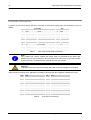
Conventions
The following table lists conventions used throughout this guide.
Warnings and Important Notices:
Warning:
Information to alert you to potential damage to a program, system or device or potential
personal injury
Information note:
Indicates important features or instructions to observe
An0065. CPU-1450 Soft Power Management
(This page is intentionally left blank.)
Table of Contents
Conventions ................................................................................................................................................... 3
Table of Contents ............................................................................................................................................ 5
Chapter 1
The Soft Power Management.................................................................................................... 7
Chapter 2 CPU-1450 SPM block diagram architecture ............................................................................ 9
Intel 82801 ICH2 and System Power States......................................................................................... 11
System Power Planes ........................................................................................................................... 12
Power Management interface signals ................................................................................................... 12
Event Input Signals and Their Usage.................................................................................................... 13
Chapter 3 CPU-1450 Power management connections......................................................................... 15
Ethernet........................................................................................................................................................ 16
The Eurotech Ethernet Transceiver ...................................................................................................... 16
Serial 1 & Serial 2 ........................................................................................................................................ 17
Auxiliary Power Connector........................................................................................................................... 18
Electrical connections .................................................................................................................................. 19
Development Kit connections ...................................................................................................................... 20
Chapter 4 SPM Management .................................................................................................................... 21
Entering Low Power mode........................................................................................................................... 22
ATX Power Button ................................................................................................................................. 22
External Power Button........................................................................................................................... 22
Software ................................................................................................................................................ 22
Wake-up events ........................................................................................................................................... 23
Serial port Ring Indicator....................................................................................................................... 23
Ethernet ................................................................................................................................................. 23
External Power Button PWRBTN# ........................................................................................................ 24
Wake on RTC ........................................................................................................................................ 24
Chapter 5 Soft Power Management Registers........................................................................................ 25
Intel® 82801BA I/O Controller Hub 2 (ICH2) ............................................................................................... 26
PM1_STS Power Management 1 Status Register ................................................................................ 27
PM1_EN—Power Management 1 Enable Register .............................................................................. 28
PM1_CNT—Power Management 1 Control Register............................................................................ 29
GPE0_EN—General Purpose Event 0 Enables Register ..................................................................... 30
SuperIO National PC87364 ......................................................................................................................... 31
Super I/O Configuration D Register (SIOCFD) ..................................................................................... 32
Chapter 6 Software examples .................................................................................................................. 33
Wake on RTC alarm..................................................................................................................................... 34
Wake on Ring Indicator Pulse...................................................................................................................... 36
Wake on LAN (Ethernet).............................................................................................................................. 37
Chapter 7
CPU power consumption ........................................................................................................ 39
Chapter 8 Appendix................................................................................................................................... 41
Related Software.......................................................................................................................................... 43
Related Documents...................................................................................................................................... 43
(This page is intentionally left blank.)
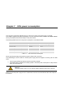
Chapter 1
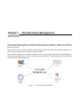
The Soft Power Management
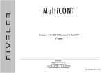
Soft Power Management (SPM) is a technique that allows users to put the CPU module into a low power
mode (therefore decreasing power consumption) while keeping the capacity to restart work as soon as
something happens.
When the CPU-1450 module is powered off with SPM, just a little part of the board remains supplied. This
part monitors the system inputs, looking for wake-up events.
The low power mode can be activated via software or via a power button, whereas can be deactivated by
either the power button or from one of a number of wake-up events (i.e. receiving packets from network line,
or an alarm at a predetermined time).
Figure 1.
Power Management System
(This page is intentionally left blank.)
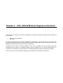
Chapter 2
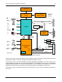
CPU-1450 SPM block diagram architecture
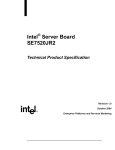
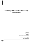
The CPU-1450 is a PC/104-Plus module realized with a mezzanine architecture approach and comprises of
two modules:
Celeron Processor Module
PIII Carrier
For better understanding of the Power Management functionality of the CPU-1450 we have shown the
following block logic architecture that focuses on the chipset that manages the power saving functions. In the
diagram the dotted lines show the previous block differences.
Consider that the Celeron Processor Module is fully ACPI compatible but the PIII Carrier has been
developed with the support for APM-based legacy power management for non-ACPI implementations. In
conclusion the complete CPU-1450 assembly is only APM-based legacy power management compliant.
The core of the CPU-1450 soft power management is based on the Intel 82801 ICH2 chipset.
CPU-1450 SPM block diagram architecture
10
Low Voltage
Intel Celeron Processor
Intel 82815
GMCH
IDE
Ultra ATA
PCI
USB
4 port
AC97
Processor
Module
Celeron
PC133 SDRAM
On Board 256MB
+5V
Intel 82801
ICH2
LTC1536
Ethernet
10/100Mb
+3V3
PWROK
PCI to ISA
bridge
PWRBTN#
VGA
LPC
SLP_S3#
SLP_S5#
+5V
+3V3
Serial 1
and 2
Parallel
Port
Keyboard
Mouse
ISA
+5VSB
+3V3SB
National Instrument
PC87364
Super IO
PWBTOUT
+5V
JPR2
Default 1-2
+5VSB
PWRBTN#
J9
PWRBTN #
PSON#
RTC
Carrier PIII
Figure 2.
CPU-1450 Block Diagram
The colours used in the previous diagram show the different power lines used to supply peripherals during
different power states. The chipset can easily understand the wake-up source.
A good point of start, to better understand the Power Management capabilities, is to refer directly to the
chipset datasheet; consider that the CPU-1450 architecture is developed with the support for APM-based
legacy power management for non ACPI implementations, it is not possible to refer exactly to the previous
chipsets data sheets without considering some restrictions based on the hardware choices made.
The following section is intended to describe some restrictions the user needs to understand regarding the
CPU-1450.
An0065. CPU-1450 Soft Power Management
11
CPU-1450 SPM block diagram architecture
Intel 82801 ICH2 and System Power States
Table 1 shows the power states defined for ICH2-based platforms, the state names generally match the
corresponding ACPI states, the hardware implementation of the CPU-1450 assembly does not support the
greyed areas listed in the following table:
State/Sub-states
G0/S0/C0
G0/S0/C1
G0/S0/C2
G1/S1
G1/S3
G1/S4
G2/S5
G3
Legacy Name / Description
Full On: Processor operating. Individual devices may be shut down to save power. The different processor
operating levels are defined by Cx states, as shown in Table 4: Transitions Rules for ICH2 Within the C0 state, the
ICH2 can throttle the STPCLK# signal to reduce power consumption.
Auto-Halt: The processor has executed an Auto-Halt instruction and is not executing code. The processor snoops
the bus and maintains cache coherency.
Stop-Grant: The STPCLK# signal goes active to the processor. The processor performs a Stop-Grant cycle, halts
its instruction stream, and remains in that state until the STPCLK# signal goes inactive. In the Stop-Grant state,
the processor snoops the bus and maintains cache coherency.
Stop-Grant: Similar to G0/S0/C2 state. The ICH2 also has the option to assert the CPUSLP# signal to further
reduce processor power consumption.
Suspend-To-RAM (STR): The system context is maintained in system DRAM, but power is shut off to non-critical
circuits. Memory is retained and refreshes continue. All clocks stop except RTC clock.
Suspend-To-Disk (STD)1: The context of the system is maintained on the disk. All power is then shut off to the
system except for the logic required to resume. Externally appears same as S5, but may have different wake
events.
Soft Off (SOFF): System context is not maintained. All power is shut off except for the logic required to restart. A
full boot is required when waking.
Mechanical OFF (MOFF): System context not maintained. All power is shut off except for the RTC. No “Wake”
events are possible, because the system does not have any power. This state occurs if the user removes the
batteries, turns off a mechanical switch, or if the system power supply is at a level that is insufficient to power the
“waking” logic. When system power returns, transition depends on the state just prior to the entry to G3 and the
AFTERG3 bit in the GEN_PMCON3 register (D31:F0, offset A4).
Table 1.
General Power States for Systems using ICH2
This table gives useful information, limited to the scope of this application note. For a more detailed
description refer to 82801 ICH2 Datasheet from Intel.
1
Considering that the standard O.S. management usually needs an ACPI hardware platform to manage the Suspend to
Disk functionality, also if the hardware allows the user to enter this mode, specific SW management, not provided by
Eurotech S.p.A., needs to be developed to fulfil this mode.
An0065. CPU-1450 Soft Power Management
CPU-1450 SPM block diagram architecture
12
System Power Planes
The system has several independent power planes, as described in the following table.
Note that when a particular power plane is shut off, it should go to a 0V level.
Plane
Controlled by
MAIN
SLP_S3# signal
RESUME
Always present
Description
When SLP_S3# goes active (low), power is shut off to any circuit not required to wake the
system. Since the ACPI standard S3 state requires that the memory context be preserved,
power should be retained to the main memory. However the CPU-1450 does not support the
Suspend-to-Ram, so the main memory is shutdown together with the main plane.
The processor, main memory, devices on the PCI bus, LPC interface, downstream hub
interface and AGP will typically be shut off when the Main power plane is shut, although
there may be small subsections powered.
In this plane there are the ICH2 resume logic, Ethernet controller and others individual
subsystems used for power management. This plane is powered from +5VSB OR +3V3SB.
Please refer Error! Reference source not found. for more information.
Table 2.
System power planes
Power Management interface signals
The power management may be entered or exited depending on some specific signals listed in Table 3:
Name
Type
SLP_S3#
Internal
PWRBTN#
Input
RI#
Input
PSON# or ATX_ON
VDD
Output
Input
+5VSB
Input
Description
Power plane control. This signal is used to shut off power to all non-critical systems when in S3
(Suspend To RAM), S4 (Suspend to Disk) or S5 (Soft Off) states
The Power Button will cause SMI# or SCI to indicate a system request to go to a sleep state. If the
system is already in a sleep state, this signal will cause a wake event.
If PWRBTN# is pressed for more than 4 seconds, this will cause an unconditional transition (power
button override) to the S5 state with only the PWRBTN# available as a wake event. Override will
occur even if the system is in the S1-S4 states. This signal has an internal pull-up resistor.
From the modem interface. This signal can be enabled as a wake event; this is preserved across
power failures.
Power-On command to ATX Power supply. When PSON# is low the ATX power supply is turned on.
Main power from the ATX Power supply. It can be shut off from power management controller.
+5 Volts-Always from the ATX Power supply. It is never shut off unless the user turns off a
mechanical switch.
Table 3.
Power management for interface signals
In the rest of this document we will analyse the signals considering the related programming activities.
An0065. CPU-1450 Soft Power Management
13
CPU-1450 SPM block diagram architecture
Event Input Signals and Their Usage
Transitions rules for ICH2:
Present State
G0/S0/C0
G0/S0/C1
G0/S0/C2
G0/S0/C3
(ICH2-M only)
G1/S1,
G1/S3, or
G1/S4
G2/S5
Transition Trigger
Processor halt instruction
Level 2 Read
Level 3 Read
SLP_EN bit set
Power Button Override
Mechanical Off / Power Failure
Any Enabled Break Event
STPCLK# goes active
Power Button Override
Power Failure
Any Enabled Break Event
STPCLK# goes inactive and previously in C1
Power Button Override
Power Failure
Any Enabled Break Event
STPCLK# goes inactive and previously in C1
Power Button Override
Power Failure
Any Enabled Wake Event
Power Button Override
Power Failure
Any Enabled Wake Event
Power Failure
Power Returns
G3
Table 4.
Next State
G0/S0/C1
G0/S0/C2
G0/S0/C3
G1/Sx or G2/S5state
G2/S5
G3
G0/S0/C0
G0/S0/C2
G2/S5
G3
G0/S0/C0
G0/S0/C1
G2/S5
G3
G0/S0/C0
G0/S0/C1
G2/S5
G3
G0/S0/C0 (For ICH2-M, see note 2)
G2/S5
G3
G0/S0/C0 (For ICH2-M, see note 2)
G3
Optional to go to S0/C0 (reboot) or G2/S5 (stay off until power
button pressed or other wake event). (For ICH2 and ICH2-M,
see Note 1) (For ICH2-M, see note 2)
Transitions Rules for ICH2
An0065. CPU-1450 Soft Power Management
(This page is intentionally left blank.)
Chapter 3
CPU-1450 Power management connections
To access the Soft Power Management capabilities of the CPU-1450, specific connections need to be made;
this chapter is intended to document the connections versus the wake-up devices and to supply the CPU1450 in a Power Management compliant mode.
Considering that we support the following external wake-up capabilities:
Wake-On-LAN
Serial Ring Indicator
Power Button
We will document the connections related to the previous functions and the power connections to supply the
CPU, we recommend following the instructions using a CPU-1450 development system to simplify the power
management testing processes.
CPU-1450 Power management connections
16
Ethernet
The CPU-1450 J12 connector is used for the Ethernet connection during the Wake on LAN events.
J12
Ethernet
Figure 3.
J12Connector Layout
Table 5.
J12 Connector pin out
Pin #
Signal
1
+3.3VSB
2
ACTIVITY LED
3
RX+
4
RX-
5
LINK LED
6
GND
7
TX+
8
TX-
The Eurotech Ethernet Transceiver
To establish an Ethernet connection an Ethernet Transceiver must be used. Eurotech supplies a Transceiver
that can be placed between the J12 of the CPU module and the RJ45 network cable.
An0065. CPU-1450 Soft Power Management
17
CPU-1450 Power management connections
Serial 1 & Serial 2
The CPU-1450 J8 connector is used for the Parallel, Serial 1 and Serial 2 ports. In the soft power
management the Ring Indicator signal on the Serial sections can be used as a wake-up event.
The signal level applied to the RI pins should be greater than 3V because this signal is applied to a GATE of
a transistor that drives the RI pin of the ICH2. Furthermore, the high level must be applied using a current
limiting resistor. The limiting resistor should be 1-kOhm for each volt applied, limiting the current below 1mA.
Parallel
Serial1, Serial2
Figure 4.
J8 Connector Layout
Serial 1
Pin #
Description
Pin #
Description
23
DCD1
24
DSR1
25
RX1
26
RTS1
27
TX1
28
CTS1
29
DTR1
30
RI1
Serial 2
Pin #
Description
Pin #
Description
31
GND
32
DCD2
33
DSR2
34
RX2
35
RTS2
36
TX2
37
CTS2
38
DTR2
39
RI2
40
GND
Table 6.
J8 Connector pin out
An0065. CPU-1450 Soft Power Management
CPU-1450 Power management connections
18
Auxiliary Power Connector
The CPU-1450 connector J9 is a 12-Pin (6x2) 2.54mm pitch connector and is used to power the module as
an alternative to the PC/104-Plus bus, this connector also carries signals for power management
J9
Auxiliary
Power
Figure 5.
Pin #
Signal
J9 Connector layout
Pin #
Signal
1
GND
2
VDD
3
N.C.
4
+12v
5
-5V
6
-12V
7
GND
8
VDD
9
N.C.
10
PWRBTN# (3)
11
+5VSB (1)
12
PSON# (2)
(1)
+5VSB: +5 Volts-Always from the ATX Power supply
PSON#: Power-On command to ATX Power supply
(3)
PWRBTN or Power button :If the soft power management is enabled, a low signal in this pin turns the
system on or off.
(2)
Notes:
The +5VSB (Volt Stand-By) voltage is useful for Power management applications only.
The +12VDC and -5VDC voltages are neither used nor generated by the CPU-1450
module: they are only conveyed on the PC/104-Plus bus (connector J1) and can be
used by other devices or modules that are stacked onto the CPU module.
Warning:
Improper connection of the power supply will result in serious damage to the module.
An0065. CPU-1450 Soft Power Management
19
CPU-1450 Power management connections
Electrical connections
In general if you want to supply the CPU-1450 with an ATX power supply here the connections you've to
realize:
Pin
1
2
3
4
5
6
7
8
9
10
11
12
Signal
GND
VDD (+5VDC)
N.C.
+12VDC
N.C.
-12VDC
GND
VDD (+5VDC)
N.C.
PWR_BTN
+5VSB
ATX ON
J9 Aux PWR
Description
Ground
+5V DC signal
Not connected
+12 VDC signal
Not connected
-12 VDC signal
Ground
+5 VDC signal
Not connected
Power Button
Always high (ATX only)
ATX Power on signal
Table 7.
Pin
5
4
-10
-12
15
6
--9
14
ATX
Wire Colour
Black
Red
N.C.
Yellow
N.C.
Blue
Black
Red
N.C.
N.C.
Purple
Green
CPU-1450 to ATX cable connections
Note:
The +12VDC and -12VDC voltages are neither used nor generated by the CPU-1450
module: they are only conveyed on the PC/104Plus bus (connector J1) and can be used
by other devices or modules that are stacked onto the CPU module.
Warning:
Improper connection of the power supply will result in serious damage for the module.
Table 8 shows the pinout of the Standard ATX female connector with the suggested 18AWG wire colour.
Pin
Signal
11
+3.3 VDC - Orange (22AWG)
Pin
1
11
3.3V sense - Brown (22AWG)
1
12
-12 VDC Blue
2
13
Black COM
3
14
Green PS-ON
4
15
Black COM
5
16
Black COM
6
17
Black COM
7
18
White -5 VDC
8
19
Red +5 VDC
9
20
Red +5 VDC
10
Table 8.
Signal
+3.3 VDC - Orange
+3.3 VDC - Orange
+3.3 VDC - Orange
COM - Black
+5 VDC - Red
COM - Black
+5 VDC - Red
COM - Black
POK - Gray
+5VSB - Purple
+12 VDC - Yellow
ATX Power Connections
An0065. CPU-1450 Soft Power Management
CPU-1450 Power management connections
20
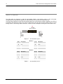
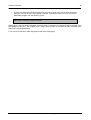
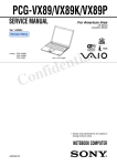
Development Kit connections
A good platform to experiment with the power saving capabilities is the Eurotech development kit; using this
system you can minimize the number of power connections wired in a safe way over the motherboard.
We suggest using the same reference colours listed in Table 8 with AWG18 wire.
The connections you need to realize are limited and shown in the following image:
J23 DTK-1450
J9 CPU-1450
Pin 1 PSON#
Pin 2 GND
Pin 3 Not Connected
Pin 4 +5VSB
Pin 12
Pin 11
Pin 10
Pin 7
PSON#
+5VSB
PWRBTN#
GND
PWRBTN#
Figure 6.
DTK Power Saving Connections
In this application note we assume that you are using a development system where a CPU-1450 is installed
with the connections described on Figure 6.
Warning:
Handle the module with care, considering that the board remains supplied even when it
is not operating. Remove the mains supply from the system when you need to work on
the development kit.
An0065. CPU-1450 Soft Power Management
Chapter 4
SPM Management
The Soft Power Management capabilities of the CPU-1450 are integrated in the ICH2 82801 and the Super
I/O PC87364.
The CPU has the capability to be placed in a low-power operating mode where CPU activity is stopped and
power consumption reduced. Operating in this mode is possible by supplying the CPU with the power supply
architecture previously described.
All wake-up event registers and related logic are battery backed-up to retain the configuration of wake-up
events upon a loss of power (i.e., VDD=0V and +5VSB=0V). The battery can be connected through pin 7 (+)
and pin 1 (-) of the “Multifunction, VGA & Ethernet” connector (J7). The Battery supply voltage must be 3.0 V
(minimum 2.4 V, maximum 4.0 V).
The low power mode can be activated via software, whereas can be deactivated from either the power
button or from one of a number of wake-up events.
The Soft Power Management has a few fundamental points:
Initialise the SPM CPU peripheral to enable wake-up events
Place the CPU in a low-power mode
Waiting for Wake-up events
SPM Management
22
Entering Low Power mode
This chapter describes how to enter the low-power mode and the events that allow the user to wake-up the
CPU-1450 from the sleep state.
To minimize power consumption the CPU has to be placed into a low power consumption mode, this may be
done via software.
ATX Power Button
If you use the ATX power-button you can shutdown the System as a standard ATX PC whenever you want,
this is not a correct mode to manage the SPM mode, because, in this way your application does not have
any information regarding the power on/off modes.
When you experiment with the Soft Power Management using the development kit remember to leave the
ATX power button in the power off position.
External Power Button
The external Power Button (PWR_BTN pin 10 of the J11 connector) has to be connected between pin 10
and 7 of the J11 connector to allow the user to power-down or power-up the CPU. This feature may be
enabled or disabled by writing the appropriate values on the ICH2 registers.
Looking at the Error! Reference source not found. users can analyse the PWR_BTN signal path that can
be routed via the JPR2 to the ICH2 82801 or the Super I/O PC87364. By default the PWR_BTN signal is
routed to the ICH2 chipset.
Currently this functionality is not implemented.
Software
You can enter Low Power Mode by writing to the appropriate register using software; this allows you to
shutdown the CPU remotely. The SPM may be managed by software by programming the Software Power
Down Registers as described later in this document.
An0065. CPU-1450 Soft Power Management
23
SPM Management
Wake-up events
The hardware of the CPU-1450 has been developed to allow the user to manage the Soft Power
Management modes with the following wake-up event sources:
Serial Port Ring Indicator pin
Ethernet
External Power Button
Wake on RTC
All the possible wake-up events can be enabled or disabled by setting the Soft Power Enable Registers. The
user can also know what event has occurred to turn-on the power by reading the Soft Power Status
Registers. Note that the status bit gets set if the wake-up event occurs, whether or not it is enable as a wakeup function by setting the corresponding bit in Soft Power Enable Register. However only the enabled wakeup functions will turn the system power on.
Serial port Ring Indicator
The hardware wake-up event from the sleeping state is activated with a high signal at this pin. Levels should
be greater than 3V because this signal is applied to a GATE of a transistor that drives the RI pin of the ICH2.
Furthermore the high level must be applied using a current limiting resistor, the limiting resistor has to be
1kOhm for each volt applied, limiting the current below 1mA.
Note that Filtering / De-bounce on RI# will not be done in ICH2 or in CPU-1450.
Please refer to Chapter 6 for a practical example using the wake on nRINGING functionality.
Ethernet
The CPU-1450 module uses the Ethernet controller integrated into ICH2. This controller is compliant to ACPI
(Rev. 1.0), PCI Power management (Rev 1.0) and monitors the network looking for a Wake-up Frame, a
Magic Packet or a Link change and notifies the event via the internal PME# signal.
Magic Packet from the network
A remote Computer can utilize the Magic packet* to wake-up the module. Once the Module has been
enabled for Magic Packet* wake-up and has been put into appropriate state, it scans all incoming packets
addressed to the node for a specific data sequence, which indicates to the controller that this is a Magic
Packet* frame. A Magic Packet* frame must also meet the basic requirements: Destination address + Source
address + data + CRC. The destination address may be the node ID of the receiving station or a multicast
address, which includes the broadcast address. The specific sequence consists of 16 duplications of the 6byte ID registers, with no breaks or interrupts. This sequence can be located anywhere within the packet, but
must be preceded by a synchronization stream, 6 bytes of FFh. The device will also accept a multicast
address, as long as the 16 duplications of the IEEE address match the address of the ID registers. If the
Node ID is 11h 22h 33h 44h 55h 66h, then the magic frame’ s format is like the following:
Destination address + source address + MISC + FF FF FF FF FF FF + MISC + 11 22 33 44 55 66 + 11 22 33
44 55 66 + 11 22 33 44 55 66 + 11 22 33 44 55 66 + 11 22 33 44 55 66 + 11 22 33 44 55 66 + 11 22 33 44
55 66 + 11 22 33 44 55 66 + 11 22 33 44 55 66 + 11 22 33 44 55 66 + 11 22 33 44 55 66 + 11 22 33 44 55
66 + 11 22 33 44 55 66 + 11 22 33 44 55 66 + 11 22 33 44 55 66 + 11 22 33 44 55 66 + MISC + CRC
Please refer to Chapter 6 for a practical example using the Magic Packet functionality.
An0065. CPU-1450 Soft Power Management
SPM Management
24
External Power Button PWRBTN#
A low signal in the Power Button pin (if enabled) can be used to turn-on or turn-off the system from the low
power mode. A low level at this pin activates the wake-up functionality.
Wake on RTC
A hardware wake-up event from the sleeping state can be made at a predetermined time with an RTC alarm.
In this case please be careful that the RTC is upgraded (Eurotech BIOS provides a user friendly interface to
update the time and date), users have to initialise the RTC alarm registers and place the CPU into Low
power consumption mode, when RTC reach RTC alarm count the CPU is waked up.
Please refer to Chapter 6 for a practical example using the Wake on RTC functionality.
An0065. CPU-1450 Soft Power Management
Chapter 5
Soft Power Management Registers
The SPM register model consists of a number of fixed register blocks that perform designated functions. A
register block consists of a number of registers that perform Status, Enable and Control Functions.
Status bits are only set through some defined hardware events.
Unless otherwise noted, Status bits are cleared by writing a HIGH to that bit position, and upon VTR
POR. Writing 0 has no effect.
Status bits only generate interrupts while their associated bit in the enable register is set.
Function bit positions in the status register have the same bit position in the enable register.
Wake-up event configuration is retained by the battery backup power.
For a first approach to power management it is not required to know all the registers involved.
The program examples in the next chapter set the power mode as required for a quick test of power
management.
As a reference, for a more detailed approach, the following pages show a list of interesting registers used in
the code examples.
Soft Power Management Registers
26
Intel® 82801BA I/O Controller Hub 2 (ICH2)
The following tables report the ICH2 registers useful for the power management.
Name
PMCSR
PM1_STS
Address
PCI Configuration Register
Bus 1, Device 8, Function 0, offset E0h
I/O address 6000h
PM1_EN
I/O address 6002h
PM1_CNT
I/O address 6004h
GPE0_EN
I/O address 602Ah
Table 9.
Function
Power Management Control/Status Register of LAN
Controller. Used to enable PME and set Power State.
Power Management 1 Status Register. Used to read and
clear wake status.
Power Management 1 Enable Register. Used to enable
wake events as RTC.
Power Management 1 Control Register. Used to set sleep
modes.
General Purpose Event 0 Enables Register. Used to enable
wake events as Ring Indicator and PME.
Interesting ICH2 registers
For a more detailed description please refer to Intel® 82801BA I/O Controller Hub 2 (ICH2) datasheet.
An0065. CPU-1450 Soft Power Management
27
Soft Power Management Registers
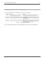
PM1_STS Power Management 1 Status Register
I/O Address
(ACPI PM1a_EVT_BLK) Attribute
Default Value
Size
Lockable
Usage
Power Well
6000h
R/WC
0000h
16-bit
No
ACPI or Legacy
Bits 0–7:
Core,
Bits 8–15:
Resume
Except Bit 11 in RTC
If bit 10 or 8 in this register is 1 and the corresponding _EN bit is set in the PM1_EN register, ICH2
generates a Wake Event. Once back in an S0 state (or if already in S0 state when the event occurs), ICH2
also generates an SCI if the SCI_EN bit is set or an SMI# if the SCI_EN bit is not set.
Note: Bit 5 does not cause an SMI# or a wake event. Bit 0 does not cause a wake event but can cause an
SMI# or SCI.
Bit
15
14:12
11
10
9
8
7:6
5
4
3:1
0
Description
Wake Status (WAK_STS)—R/WC. This bit is not affected by hard resets caused by a CF9 write but is reset by RSMRST#.
0 = Software clears this bit by writing a 1 to the bit position.
1 = Set by hardware when the system is in one of the sleep states (via the SLP_EN bit) and an enabled wake event occurs.
Upon setting this bit, the ICH2 will transition the system to the ON state.
If the AFTERG3_EN bit is not set and a power failure occurs without the SLP_EN bit set, the system will return to an S0 state
when power returns, and the WAK_STS bit will not be set. For the 82801BAM ICH2-M, power failure could result from removing
the batteries.
If the AFTERG3_EN bit is set and a power failure occurs without the SLP_EN bit having been set, the system will go into an S5
state when power returns and a subsequent wake event will cause the WAK_STS bit to be set. Note that any subsequent wake
event would have to be caused by either a Power Button press or an enabled wake event that was preserved through the power
failure (enable bit in the RTC well).
Reserved
Power Button Override Status (PRBTNOR_STS)—R/WC. This bit is not affected by hard resets caused by a CF9 write and is
not reset by RSMRST#. Thus, this bit will be preserved through a power failure.
0 = The BIOS or SCI handler can clear this bit by writing a 1 to it.
1 = Set by hardware anytime a Power Button Override Event occurs which occurs when the power button is pressed for at least
4 consecutive seconds. The power button override causes an unconditional transition to the S5 state and sets the AFTERG3 bit.
This bit can also be set by the SMBus Slave logic.
RTC Status (RTC_STS)—R/WC. This bit is not affected by hard resets caused by a CF9 write but is reset by RSMRST#.
0 = Software clears this bit by writing a 1 to the bit position.
1 = Set by hardware when the RTC generates an alarm (assertion of the IRQ8# signal). Additionally if the RTC_EN bit is set, the
setting of the RTC_STS bit will generate a wake event.
Reserved
Power Button Status (PWRBTN_STS)—R/WC. This bit is not affected by hard resets caused by a
CF9 write.
1 = This bit is set by hardware when the PWRBTN# signal is asserted Low, independent of any other enable bit.
In the S0 state, while PWRBTN_EN and PWRBTN_STS are both set, an SCI (or SMI# if SCI_EN is not set) will be generated. In
any sleeping state S1–S5, while PWRBTN_EN and PWRBTN_STS are both set, a wake event is generated.
0 = If the PWRBTN# signal is held low for more than 4 seconds, the hardware clears the PWRBTN_STS bit, sets the
PWRBTNOR_STS bit, and the system transitions to the S5 state with only PWRBTN# enabled as a wake event. This bit can be
cleared by software by writing a one to the bit position.
Reserved
Global Status (GBL _STS)—R/WC.
1 = Set when an SCI is generated due to BIOS wanting the attention of the SCI handler. BIOS has a corresponding bit,
BIOS_RLS, which will cause an SCI and set this bit.
0 = The SCI handler should then clear this bit by writing a 1 to the bit location.
ICH2 (82801BA):
Reserved
Reserved
Timer Overflow Status (TMROF_STS)—R/WC.
1 = This bit gets set any time bit 22 of the 24-bit timer goes high (bits are numbered from 0 to 23).
This will occur every 2.3435 seconds. When the TMROF_EN bit is set, then the setting of the TMROF_STS bit will additionally
generate an SCI or SMI# (depending on the SCI_EN).
0 = The SCI or SMI# handler clears this bit by writing a 1 to the bit location.
Table 10.
PM1_STS Power Management 1 Status Register
An0065. CPU-1450 Soft Power Management
Soft Power Management Registers
28
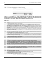
PM1_EN—Power Management 1 Enable Register
I/O Address
(ACPI PM1a_EVT_BLK) Attribute
Default Value
Size
Lockable
Usage
Power Well
Bit
15:11
10
8
5
0
6002h
R/W
0000h
16-bit
No
ACPI or Legacy
Bits 0–7:
Bits 8–15:
Core,
Resume
Description
Reserved.
RTC Event Enable (RTC_EN)—R/W. This bit is in the RTC well to allow an RTC event to wake after
a power failure. This bit is not cleared by any reset other than RTCRST# or a Power Button Override
event.
1 = An SCI (or SMI#) or wake event will occur when this bit is set and the RTC_STS bit goes active.
0 = No SCI (or SMI#) or wake event is generated then RTC_STS goes active.
Power Button Enable (PWRBTN_EN)—R/W. This bit is used to enable the setting of the
PWRBTN_STS bit to generate a power management event (SMI#, SCI). PWRBTN_EN has no effect
on the PWRBTN_STS bit being set by the assertion of the power button. The Power Button is
always enabled as a Wake event.
0 = Disable.
1 = Enable.
Global Enable (GBL_EN)—R/W. When both the GBL_EN and the GBL_STS are set, an SCI is
raised.
0 = Disable.
1 = Enable SCI on GBL_STS going active.
Timer Overflow Interrupt Enable (TMROF_EN)—R/W. Works in conjunction with the SCI_EN bit as
described below:
TMROF_EN SCI_EN Effect when TMROF_STS is set
0 x No SMI# or SCI
1 0 SMI#
1 1 SCI
Table 11.
PM1_EN—Power Management 1 Enable Register
An0065. CPU-1450 Soft Power Management
29
Soft Power Management Registers
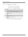
PM1_CNT—Power Management 1 Control Register
I/O Address
(ACPI PM1a_EVT_BLK) Attribute
Default Value
Size
Lockable
Usage
Power Well
Bit
13
12:10
2
1
0
6004h
R/W
0000h
32-bit
No
ACPI or Legacy
Bits 0–7:
Bits 8–15:
Core,
Resume
Description
Sleep Enable (SLP_EN)—WO. Setting this bit causes the system to sequence into the Sleep state defined by the SLP_TYP
field.
Sleep Type (SLP_TYP)—R/W. This 3-bit field defines the type of Sleep the system should enter when the SLP_EN bit is set to
1.
000 = ON: Typically maps to S0 state.
011 = Reserved
100 = Reserved
101 = Suspend-To-RAM. Assert SLP_S1# and SLP_S3#; typically, maps to S3 state.
110 = Suspend-To-Disk. Assert SLP_S1#, SLP_S3#, and SLP_S5# SLP_S3# and, SLP_S5#; typically, maps to S4 state.
111 = Soft Off. Assert SLP_S1#, SLP_S3#, and SLP_S5# SLP_S3#, and SLP_S5#; typically, maps to S5 state.
Global Release (GBL_RLS)—WO.
1 = ACPI software writes a 1 to this bit to raise an event to the BIOS. BIOS software has corresponding enable and status bits
to control its ability to receive ACPI events.
0 = This bit always reads as 0.
ICH2 (82801BA):
Reserved
ICH2-M (82801BAM):
Bus Master Reload (BM_RLD)— R/W. This bit is reset to 0 by PCIRST#
0 = Bus master requests do not cause a break from the C3 state.
1 = Enable Bus Master requests (internal, external or AGPBUSY#) to cause a break from the C3 state.
SCI Enable (SCI_EN)—R/W. Selects the SCI interrupt or the SMI# interrupt for various events including the bits in the
PM1_STS register (bit 10, 8, 0), and bits in GPE0_STS.
0 = These events will generate an SMI#.
1 = These events will generate an SCI.
001 = ICH2 (82801BA): Assert STPCLK#. Puts processor in Stop-Grant state. Optional to assert
CPUSLP# to put processor in sleep state: Typically, maps to S1 state.
ICH2-M (82801BAM): Reserved.
010 = ICH2 (82801BA): Reserved
ICH2-M (82801BAM): Assert SLP_S1#: Typically, maps to S1 state.
Table 12.
PM1_CNT—Power Management 1 Control Register
An0065. CPU-1450 Soft Power Management
Soft Power Management Registers
30
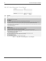
GPE0_EN—General Purpose Event 0 Enables Register
I/O Address
(ACPI PM1a_EVT_BLK) Attribute
Default Value
Size
Lockable
Usage
Power Well
602h
R/W
0000h
16-bit
No
ACPI
Bits 0–7:
Bits 8–15:
Core,
RTC
Note: This register is symmetrical to the General Purpose Event 0 Status Register. All the bits in this register
should be cleared to 0 based on a Power Button Override. The resume well bits are all cleared by
RSMRST#. The RTC sell bits are cleared by RTCRST#.
Bit
15:12
11
10
9
8
7
6
5
4
3
2
1
0
Description
Reserved.
PME# Enable (PME_EN)—R/W.
0 = Disable.
1 = Enables the setting of the PME_STS to generate a wake event and/or an SCI. PME# can be a wake event from the S1–S4
state or from S5 (if entered via SLP_EN, but not power button override).
ICH2 (82801BA):
Reserved
Reserved
RI_EN—R/W. The value of this bit will be maintained through a G3 state and is not affected by a hard reset caused by
RSMRST# or a CF9h write. Assertion of RTCRST# resets this bit.
0 = Disable.
1 = Enables the setting of the RI_STS to generate a wake event.
Reserved
TCO SCI Enable (TCOSCI_EN)—R/W.
0 = Disable.
1 = Enables the setting of the TCOSCI_STS to generate an SCI.
AC97 Enable (AC97_EN)—R/W.
0 = Disable.
1 = Enables the setting of the AC97_STS to generate a wake event.
USB Controller 2 Enable (USB2_EN)—R/W.
0 = Disable.
1 = Enables the setting of the USB2_STS to generate a wake event.
USB Controller 1 Enable (USB1_EN)—R/W.
0 = Disable.
1 = Enables the setting of the USB1_STS to generate a wake event.
Thermal Pin Polarity (THRM#_POL)—R/W. This bit controls the polarity of the THRM# pin needed to set the THRM_STS bit.
0 = Low value on the THRM# signal will set the THRM_STS bit.
1 = HIGH value on the THRM# signal will set the THRM_STS bit.
Reserved
Thermal Signal Reporting Enable (THRM_EN)—R/W.
0 = Disable.
1 = Active assertion of the THRM# signal (as defined by the THRM_POL bit) will set the
THRM_STS bit and generate a power management event (SCI or SMI).
Table 13.
GPE0_EN—General Purpose Event 0 Enables Register
An0065. CPU-1450 Soft Power Management
31
Soft Power Management Registers
SuperIO National PC87364
The following tables show the National Super I/O PC87364 registers useful for the power management:
Access to the Super I/O configuration registers is via an Index-Data register pair, using only two system I/O
byte locations. The base address of this register pair is determined during reset, according to the state of the
hardware strapping option on the BADDR pin. The following table shows the selected base addresses as a
function of BADDR.
BADDR
0
1
Table 14.
Index
Register
2Eh
4Eh
Data
Register
2Fh
4Fh
BADDR Strapping Options
For a more detailed description please refer to National / Winbond PC87364 128-Pin LPC Super I/O
datasheet.
An0065. CPU-1450 Soft Power Management
Soft Power Management Registers
32
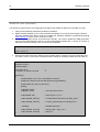
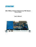
Super I/O Configuration D Register (SIOCFD)
Location Index
Type
Battery-backed register
Name
Configuration D
Register
Address
Indexed 2Dh.
Index/data pair register address is 2E/2Fh.
Figure 7.
Bit
7
2Dh
Varies per bit
6
Function
Power Management Control/Status Register. Used to set
ACPI mode for Super I/O chip .
PC87364 Super I/O interesting registers
5
4
3
2
1
0
Power
Supply Off
Power
Button
Mode
0
0
Name
LED
Polarity
Control
Last
PSON
State
PSON
Polarity
Crowbar Timeout
Resume
Last
PSON
State
Reset
0
0
Strap
1
0
Bit
7
6
5
4-3
2
1
0
1
Description
LED Polarity Control. This is a R/W bit. It determines if the LED outputs are active high or active low when they
are lit.
0: Active high (default at VSB power-up reset)
1: Active low
Last Power Supply On State. This is a RO bit. When operating in Legacy mode (bit 0 of this register is set to 0),
this bit reflects the state of the PSON pin sampled during the last power failure (no VSB), regardless of the polarity
of PSON.
0: Off
1: On
Power Supply On Polarity. This is a RO bit. The polarity of PSON is determined during VSB power-up by the
PSONPOL strap.
Crowbar Timeout. This is a R/W bit.
Bits
5 4 Value (Seconds)
0 0 0.4 to 0.9 (typical 0.6)
0 1 0.9 to 1.4 (typical 1.1)
1 0 1.4 to 1.9 (typical 1.6)
1 1 1.9 to 2.5 (typical 2.1) (default at VPP power-up reset)
Note that for any specific condition, there is a minimum gap of 0.25 seconds between the actual high limit of a
timeout setting and the low limit of the next time-out setting.
Resume Last Power Supply On State. This is a R/W bit. When it is set to 1, PSON resumes its last state, sampled
during the last power failure, after power returns. When this bit is set to 0, the PSON state is determined by the
SLPS3 state.
0: SLPS3 (default at VPP power-up reset)
1: Last PSON state. For correct operation, the system’s ACPI controller must be configured to resume to OFF.
This enables the power supply control logic to know the state of the chipset ACPI state machine after power
failure (no VDD and VSB).
Power Supply Off. This is a R/W bit. It always returns 0 when read. When using Legacy mode (bit 0 is set to 0)
and setting this bit to 1, this bit inactivates the PSON output, thereby shutting off the power supply.
0: No action (default at VPP power-up reset)
1: Inactivate PSON in Legacy mode
Power Button Mode. This is a R/W bit.
0: Legacy (default at VSB power-up reset)
1: ACPI
Table 15.
Super I/O Configuration D Register (SIOCFD)
An0065. CPU-1450 Soft Power Management
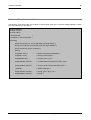
Chapter 6
Software examples
In this section there are some programs useful to set the sleep modes. The examples are developed in DOS
O.S. and compiled with Watcom C (see bibliography).
We are going to analyse some examples that may be useful understanding the following Wake-up events:
Wake On RTC
Serial Port Ring Indicator pin
Wake On LAN (Ethernet)
These software examples are also contained in the “An0065_SW_Package” available in the download area
@ www.eurotech.it (“Tools” section of the CPU-1450).
Software examples
34
Wake on RTC alarm
We start with an example that doesn’t need additional external hardware. The following code will put the
CPU module in soft-off sleep mode and wake it after 2 minutes using RTC alarm.
#include <stdio.h>
#include <conio.h>
#include <i86.h>
/* Eurotech SpA
/* Version 0.5, date 07-02-2006 */
void main()
{
printf( "Eurotech S.p.a. CPU-1450 Wake On RTC\n" );
printf( "Put to sleep a Cpu1450 and wake with RTC alarm to 2 minutes \n" );
printf( "\npress any key to continue\n");
getch();
outp(0x2E, 0x2D );
outp(0x2F, 0x19 );
/* Super IO PC87364 Initialization */
/* set ACPI mode in SIO */
/* Configure the RTC Register accessing using the Index and Target registers, */
/* refer to the following table for detailed info on register contents */
outp(0x70, 0x0 );
outp(0x71, 0x0 );
/* Configure RTC Seconds 00s*/
outp(0x70, 0x1 );
outp(0x71, 0x0 );
/* Configure RTC Seconds Alarm 00s*/
outp(0x70, 0x2 );
outp(0x71, 0x0 );
/* Configure RTC Minutes 00m*/
outp(0x70, 0x3 );
outp(0x71, 0x2 );
/* Configure RTC Minutes Alarm 02m*/
outp(0x70, 0x4 );
outp(0x71, 0x0 );
/* Configure RTC Hours 00h*/
outp(0x70, 0x5 );
outp(0x71, 0x0 );
/* Configure RTC Hours Alarm 00h*/
outp(0x70, 0xB );
outp(0x71, 0x22 );
/* Configure RTC Register B Contents */
outp(0x6003, 0x4 );
/* Programming the 2 byte of PM1_EN – PWR Manag 1 En Reg */
outpw (0x6000, 0xFFFF );
/* clr wake status and others into PM1_STS */
_disable();
/* disable interrupts */
outpw (0x6004, 0x1C00 );
outpw (0x6004, 0x3C00 );
/* set slp_type = slp_to_s5 */
/* set slp */
nd
}
The RTC contains two sets of indexed registers that are accessed using the two separate Index and Target
registers (70h/71h or 72h/73h), as shown in the following table:
An0065. CPU-1450 Soft Power Management
35
Software examples
Index
00h
01h
02h
03h
04h
05h
06h
07h
Name
Seconds
Seconds Alarm
Minutes
Minutes Alarm
Hours
Hours Alarm
Day of Week
Day of Month
Table 16.
Index
08h
09h
0Ah
0Bh
0Ch
0Dh
0Eh–7Fh
Name
Month
Year
Register A
Register B
Register C
Register D
114 Bytes of User RAM
RTC (Standard) RAM Bank
The I/O locations 70h and 71h are the standard ISA location for the real-time clock.
An0065. CPU-1450 Soft Power Management
Software examples
36
Wake on Ring Indicator Pulse
The following code will put the CPU module in soft-off sleep mode; then a positive voltage applied on serial
port Ring Indicator pin will wake it.
#include <stdio.h>
#include <conio.h>
#include <i86.h>
/* Eurotech SpA
*/
/* version 0.5 , date 07-02-2006 */
void main()
{
printf( "Eurotech S.p.a. CPU-1450 Wake On Serial Ring\n" );
printf( "Put to sleep a Cpu1450 with pme and ring enabled\n" );
printf( "\npress any key to continue\n");
getch();
outp(0x2E, 0x2D );
outp(0x2F, 0x19 );
/* Super IO PC87364 Initialization */
/* set acpi mode in SIO */
outp(0x602B, 0x9 );
/* set pme_en e ri_en */
outpw (0x6000, 0xFFFF );
/* clr wake status and others into PM1_STS */
outpw (0x6028, 0xFFFF );
/* clr pme_sts and others into GPE0_STS */
_disable();
/* disable interrupts */
outpw (0x6004, 0x1C00 );
outpw (0x6004, 0x3C00 );
/* set slp_type = slp_to_s5 */
/* set slp */
}
An0065. CPU-1450 Soft Power Management
37
Software examples
Wake on LAN (Ethernet)
The following example shows the configuration procedure that enables a Wake-On-LAN wake-up event.
1. Verify that the Network peripheral is enabled in the BIOS.
2. Detect the MAC address of your CPU-1450 Ethernet adapter, this may be done using the DIAGS
SW utility available from Intel or using the “An0065_SW_Package” available in the download area @
www.eurotech.it (“Tools” section of the CPU-1450).
3. Configure the register PMCSR of the Ethernet controller. You need to enable the PME generation.
Use a program like Bustrek to set bit 8 of PCI Configuration Register Bus 1, Device 8, Function 0,
offset E1h. Here an example of the command line for Bustrek:
C:\>Bustrek
-pwb 1 8 0 E1 41
4. Execute the same code of the "Wake on Ring Indicator Pulse " example, and put to sleep the CPU.
The CPU is now in a low power consumption state, waiting for the Magic Packet event to wake-up.
#include <stdio.h>
#include <conio.h>
#include <i86.h>
/* Eurotech SpA
/* version 0.5 , date 07-02-2006
*/
*/
void main()
{
printf("Eurotech S.p.a. CPU-1450 Wake On LAN\n");
printf("Put to sleep a Cpu1450 with pme and ring enabled\n");
printf("\npress any key to continue\n");
getch();
outp(0x2E, 0x2D);
outp(0x2F, 0x19);
/* set acpi mode in SIO */
outp(0x602B, 0x9);
/* set pme_en e ri_en */
outpw (0x6000, 0xFFFF);
/* clr wake status and others into PM1_STS */
outpw (0x6028, 0xFFFF);
/* clr pme_sts and others into GPE0_STS */
_disable();
/* disable interrupts */
outpw (0x6004, 0x1C00);
outpw (0x6004, 0x3C00);
/* set slp_type = slp_to_s5 */
/* set slp */
}
An0065. CPU-1450 Soft Power Management
Software examples
38
5. To verify the Wake-On-LAN functionality now you need to send to the CPU a Magic Packet via
Ethernet. This may be done using specific software, for example under Linux you can use the
EtherWake program with the following syntax:
Ether-wake -i ethxx XX:XX:XX:XX:XX:XX
Where ethxx is the host Ethernet adapter where the CPU is connected, the XX:XX:XX:XX:XX:XX field is the
MAC address of the CPU ; the program send a magic packet stream on the Ethernet cable compliant to the
AMD magic packet specification.
If you don’t have the ether-wake utility please refer to the bibliography.
An0065. CPU-1450 Soft Power Management
Chapter 7
CPU power consumption
The main goal of Soft Power Management is to reduce CPU power consumption when not needed.
This chapter compares the power consumption of a CPU-1450 with Celeron 400MHz and 256MB SDRAM
running in standard mode and some sleep or low power modes.
The following table list the CPU-1450 power consumption in the different states:
CPU-1450 w/ Celeron 400MHz and 256MB SDRAM
Power mode
Ethernet connection
Power consumption typical
Full power mode
Negligible
8.00 W
Soft-off or suspend-to-disk sleep mode
Ethernet disabled
0.35 W
Soft-off or suspend-to-disk sleep mode
Cable disconnected
0.75 W
Soft-off or suspend-to-disk sleep mode
Link at 10 MBIT
0.68 W
Link at 100 MBIT
0.90 W
Soft-off or suspend-to-disk sleep mode
Table 17.
CPU-1450 Power Consumption
We can see that the energy saving with low power / sleep mode is very high.
The disadvantage is that it needs an ATX-like power supply with two supplies for working with the SPM
mode:
A main supply (VDD) that could be turned on and off by software.
An auxiliary supply (+5VSB) that is always present. The whole power consumption in sleep mode is
taken from this power line.
Warning:
Once the auxiliary power is on, the board is always supplied so take care to handle it.
Without an ATX-like power supply the CPU-1450 Module could not work with SPM and the Power keeps all
the board on.
(This page is intentionally left blank.)
Chapter 8
Appendix
(This page is intentionally left blank.)
Related Software
Some software examples are contained in the “An0065_SW_Package” available in the download area @
www.eurotech.it (“Tools” section of the CPU-1450).
Related Documents
For more information please refer to the CPU-1450 user manual.
http://www.eurotech.it
Super I/O PC87364
www.national.com
ICH2 82801
www.intel.com
Open Watcom C++
http://www.openwatcom.org/index.php/Main_Page
Ether-wake
http://gsd.di.uminho.pt/jpo/software/wakeonlan/mini-howto/wol-mini-howto-3.html