1
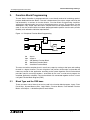
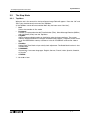
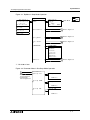
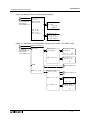
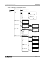
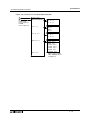
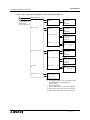
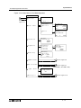
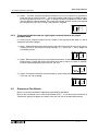
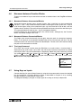
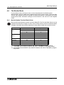
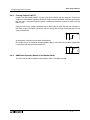
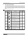
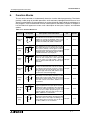
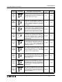
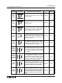
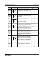
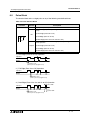
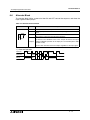
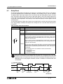
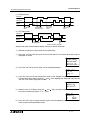
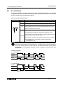
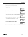
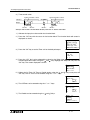
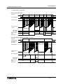
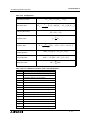
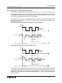
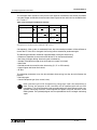
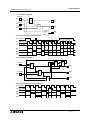
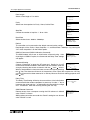
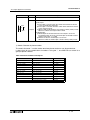
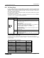
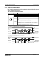
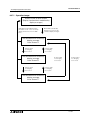
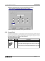
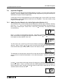
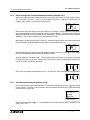
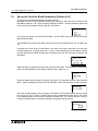
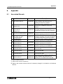
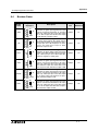
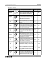
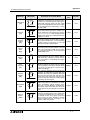
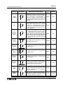
α2 Simple Application Controllers
FB Name
FB Symbol
U
D
C
P
UD
Compare
[CP]
I
000
P
O
Analog
Output
[AO]
M
E
Offset
Gain
[OG]
I
U/D Counter
[UD]
Display
[DP]
Zone
Compare
[ZC]
Schmitt
Trigger
[ST]
Hour Meter
[HM]
Speed
Detect
[SPD]
000
P
O
CP
000
P
AO
000
P
OG
I
000
P
DP
I
000
P
O
ZC
I
000
P
O
ST
I
C
000
P
O
HM
I
U
C
000
O
P
SPD
Appendix 8
Description of Function Block
Memory
Use
Section
The Up/Down Function block positively or
negatively increments the counter until a
set value is reached thereby setting the
output ON. A preset signal can also equal
the set value regardless of the current value
for the function block and thereby setting
the output ON.
22 Byte
6.12
The Compare Function Block monitors the
current value of the input pin in relation to a
preset expression. The expression consists
of =,>,>=,<,<= or <>. If the compared value
satisfies the expression subsequently the
output pin is set on.
17 Byte
6.13
The Analog Output function takes a digital
value input and delivers a corresponding
analog voltage or current to a selected
channel on the AL2-2DA module.
17 Byte
6.14
The Offset Gain Function Block is based
upon a linear function Y=A/B∗X+C to which
the value obtained from an analog input
(X:A01-A08) is set.
22Byte
6.15
The Display Function Block is used as an
interface between the user and the devices
held within the controller. Current values,
timer messages, user-defined messages
can be read.
*4
6.16
The Zone Compare Function Block
identifies whether the input value lies within
a specified upper and lower limited zonal
area and if so changes the status of the
output accordingly.
20 Byte
6.17
T h e S c h m i t t Tr i g g e r F u n c t i o n B l o ck
compares an input value to preset high and
low limits. The output is ON when the input
value reaches the high limit and then falls
below the lower limit. The function only
processes the data when the function block
is receiving an input signal.
19 Byte
6.18
The Hour Meter Function Block holds the
output status ON for a maximum of 32767
hours, 59 minutes and 59 seconds. If the
input pin is turned OFF the elapsed time
will hold its value until either the clear pin
resets the time or the input pin is turned ON
again.
19 Byte
6.19
The Speed Detect Function Block is used to
count the incoming pulses max. 20Hz (with
an extension module max. of 1kHz) for a
set period of time. The upper and lower
limits can be set from -32768 to +32767
and the Period interval’s set range is 1 to
32767 in 10ms increments.
25 Byte
6.20
8-5