1
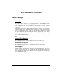
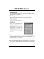
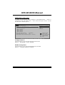
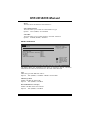
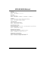
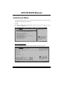
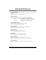
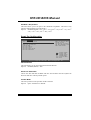
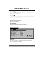
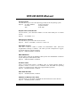
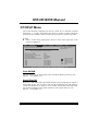
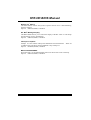
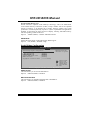
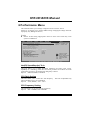
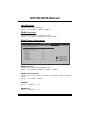
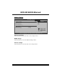
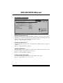
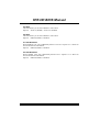
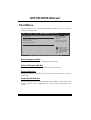
H55 HD BIOS Manual
BIOS Setup .................................................................................................1
1 Main Menu...............................................................................................3
2 Advanced Menu.......................................................................................8
3 PCIPnP Menu........................................................................................22
4 Boot Menu..............................................................................................25
5 Chipset Menu.........................................................................................28
6 Performance Menu...............................................................................33
7 Exit Menu...............................................................................................36
i
H55 HD BIOS Manual
BIOS Setup
Introduction
T he purpose of this manual is to describe the settings in the AMI BIOS Setup
program on this motherboard. The Setup program allows users to modify the basic
system configuration and save these settings to CMOS RAM. T he power of CMOS
RAM is supplied by a battery so that it retains the Setup information when the power
is turned off.
Basic Input-Output System (BIOS) determines what a computer can do without
accessing programs from a disk. T his system controls most of the input and output
devices such as keyboard, mouse, serial ports and disk drives. BIOS activates at the
first stag e o f the booting process, loading and executing the operating system. Some
additional features, such as virus and password prot ection or chipset fine-tuning
options are also included in BIOS.
T he rest of this manual will to guide you through the options and settings in BIOS
Setup.
Plug and Pla y Support
T his AMI BIOS supports the Plug and Play Version 1.0A specification.
EPA Green PC Support
T his AMI BIOS supports Version 1.03 of the EPA Green PC specification.
ACPI Support
AMI ACPI BIOS support Version 1.0/2.0 of Advanced Configuration and Power
interface specifi cation (ACPI). It provides ASL code for pow er manag ement and
device con figuration capabilities as defined in the ACPI specification, developed by
Microso ft, Intel and T oshiba.
1
H55 HD BIOS Manual
PCI Bus Support
T his AMI BIOS also supports Version 2.3 of the Intel PCI (Peripheral Component
Interconn ect) local bus speci fication.
DRAM S upport
DDR3 SDRAM (Double Data Rate III Synchronous DRAM) is supported.
Supported CP Us
T his AMI BIOS supports the Intel CPU.
Using Setup
When starting up the computer, press
<Del> during the Power-On Self-Test
(POST) to enter the BIOS setup utility.
In the BIOS setup utility, you will see
General Help description at the top right
corner, and this is providing a brief
description of the selected item.
Navigation Keys for that particular menu
are at the bottom right corner, and you can
use these keys to select item and ch ange
the settings.
General Help
Navigation Keys
Notice
z
z
z
T he default BIOS settings apply for most conditions to ensure optimum performan ce
of the motherboard. If the system becomes unstable after changing any settings,
please load the default settings to ensure system’s compatibility and stability. Use
Load Setup Default under the Exit Menu.
For better system perform ance, the BIOS firmware is being continuously updated.
T he BIOS information described in this manual is for your reference only. T he actual
BIOS information and settings on board may be slightly different from this manual.
T he content of this manual is subject to be chang ed without notice. We will not be
responsible for any mistakes found in this user’s manual and any system damage that
may be caused by wrong-settings.
2
H55 HD BIOS Manual
1 Main Menu
Once you enter AMI BIOS Setup Utility, the Main Menu will appear on the screen
providing an overview of the basic system inform ation.
Main
Advanced
PCIPnP
BIOS SETUP UTILITY
Boot
Chipset
Performance
System Overview
Exit
Use [ENTER], [TAB]
or [SHIFT-TAB] to
select a field.
AMI BIOS
Version
:01.01.01
Build Date:01/01/10
Use [+] or [-] to
configure system Time.
System Memory
Size
:
System Time
System Date
[ 00:00:00]
[Fri 01/01/2010]
> IDE/SATA Configuration
+Tab
F1
F10
ESC
Select Screen
Select Item
Change Field
Select Field
General Help
Save and Exit
Exit
vxx.xx (C)Copyright 1985-200x, American Megatrends, Inc.
AMI BIOS
Shows system information including BIOS version, built date, etc.
System Memory
Shows system memory size, VGA shard memory will be excluded..
System Time
Set the system internal clock.
System Date
Set the system date. Note that the ‘Day’ automatically changes when you set the
date.
3
H55 HD BIOS Manual
IDE/S ATA Configuration
T he BIOS will automatically detect the presence of SAT A/IDE devices. There is a
sub-menu fo r each SAT A/IDE device. Select a device and press <Enter> to enter
the sub-menu of detailed options.
BIOS SETUP UTILITY
Main
IDE/SATA Configuration
Configure SATA as
SATA#1 Configuration
Options
[IDE]
[Compatible]
> AHCI Configuration
>
>
>
>
SATA
SATA
SATA
SATA
1
2
3
4
IDE
AHCI
Disabled
Device
Device
Device
Device
Hard Disk Write Protect
[Disabled]
IDE Detect Time Out (Sec)
[35]
ATA(PI)80Pin Cable Detection [Host & Device]
Select Screen
Select Item
EnterGo to Sub Screen
F1
General Help
F10 Save and Exit
ESC Exit
vxx.xx (C)Copyright 1985-200x, American Megatrends, Inc.
Configure SATA as
T his item allows you to choose the SAT A operation mode.
Options: IDE (Default) / AHCI / Disabled
SATA#1 Configuration
T his item allows you to control the onboard SAT A controller.
Options: Compatible (Default) / Enhanced
4
H55 HD BIOS Manual
AHCI Configuration
BIOS SETUP UTILITY
Main
AHCI Settings
AHCI BIOS Support
>
>
>
>
>
>
AHCI
AHCI
AHCI
AHCI
AHCI
AHCI
Enables for supporting
[Enabled]
Port0
Port1
Port2
Port3
Port4
Port5
+F1
F10
ESC
Select Screen
Select Item
Change Option
General Help
Save and Exit
Exit
vxx.xx (C)Copyright 1985-200x, American Megatrends, Inc.
AHCI BIOS Support
T his BIOS feature controls the AHCI function of the SAT A controller.
Options: Enabled (Default) / Disabled
AHCI Port0/Port1/Port2/Port3/Port4/Port5
BIOS S ETUP UTILITY
Main
AHCI Port0
Devic e
AHCI Port0
S.M.A .R.T.
Sele ct the type
of d evice connec ted
to t he system.
:
[Aut o]
[Ena bled]
+F1
F1 0
ES C
S elect Screen
S elect Item
C hange Option
G eneral Help
S ave and Exit
E xit
vxx.xx (C)C opyright 198 5-200x, Amer ican Megatre nds, Inc.
5
H55 HD BIOS Manual
Device
This area shows the detected connected device.
SATA Port0/1/2/3/4/5
This item allows you to select the connected device type.
Options: Auto (Default) / Not Installed
S.M.A.R.T.
This item allows you to control the device S.M.A.R.T function.
Options: Enabled (Default) / Disabled
SATA 1/2/3/4 Device
BIOS SETU P U TILITY
Main
SATA1 Device
Device
Select the type
of device connected
to the system.
:
Type
[Aut o]
LBA/Large Mode
[Aut o]
Block (Multi-S ector Transfer)[Aut o]
PIO Mode
[Aut o]
DMA Mode
[Aut o]
S.M.A.R.T
[Aut o]
32Bit Data Tra nsfer
[Ena bled]
+F1
F10
ESC
S elect Screen
S elect Item
C hange Option
G eneral Help
S ave and Exit
E xit
vxx .xx (C)Copyright 1985-200x, American Me gatrends, Inc.
T he BIOS detects the information and values of resp ective devices, and these
information and values are shown below to the name of the sub-menu.
Type
Select the type of the IDE/SAT A drive.
Options: Auto (Default) / CDROM / ARMD / Not Installed
LBA/Large Mode
Enable or disable the LBA mode.
Options: Auto (Default) / Disabled
Block (Multi-Sector Transfer)
Enable or disable multi-sector trans fer.
Options: Auto (Default) / Disabled
6
H55 HD BIOS Manual
PIO Mode
Select the PIO mode.
Options: Auto (Default) / 0 / 1 / 2 / 3 / 4
DMA Mode
Select the DMA mode.
Options: Auto (Default) / SWDMA0 ~ 2 / MWDMA0 ~ 2 / UDMA0 ~ 5
S.M.A.R.T
Set the Smart Monitoring, Analysis, and Reporting T echnology.
Options: Auto (Default) / Disabled / Enabled
32Bit Data Transfer
Enable or disable 32-bit data transfer.
Options: Enabled (Default) / Disabled
Hard Disk Write Protect
Disable or enable device write protection. T his will be effective only if the device
is accessed through BIOS.
Options: Disabled (Default) / Enabled
IDE Detect Time Out (Sec)
Select the time out value for detecting IDE/SAT A devices.
Options: 35 (Default) / 30 / 25 / 20 / 15 / 10 / 5 / 0
ATA(PI) 80Pin Cable Detection
Select the mechanism for det ecting 80Pin AT A(PI) Cable..
Options: Host & Device (Default) / Host / Device
7
H55 HD BIOS Manual
2 Advanced Menu
T he Advanced Menu allows you to configu re the settings o f CPU, Super I/O, Power
Management, and other system devices.
Notice
z
Beware of that setting inappropriate values in items of this menu may cause
system to malfunction.
Main
Advanced
PCIPnP
BIOS SETUP UTILITY
Boot
Chipset
Performance
Advanced Settings
Exit
Configure CPU.
WARNING: Setting wrong values in below sections
may cause system to malfunction.
>
>
>
>
>
>
>
>
>
>
>
CPU Configuration
SuperIO Configuration
Hardware Health Configuration
Smart Fan Configuration
ACPI Configuration
Onboard PCI/PCI-E Devices Configuration
Intel VT-d Configuration
MPS Configuration
PCI Express Configuration
Smbios Configuration
USB Configuration
Select Screen
Select Item
EnterGo to Sub Screen
F1
General Help
F10 Save and Exit
ESC Exit
vxx.xx (C)Copyright 1985-200x, American Megatrends, Inc.
CPU Configuration
T his item shows the CPU information that the BIOS automatically detects.
BIOS S ETUP UTILITY
Advanced
Confi gure advanced CPU setting s
Modul e Version:01. 04
This should be e nabled
in o rder to enab le or
disa ble the “Enh anced
Halt State”.
Manuf acturer:Intel CPU
Frequ ency
:
BCLK Speed :
Cache L1
:
Cache L2
:
Cache L3
:
Ratio Status:
Ratio Actual Value :
CIE S upport
[Enabled]
Hardw are Prefetche r
[Enabled]
Adjac ent Cache Lin e Prefetch [Enabled]
Max C PUID Value Li mit
[Disabled]
Intel (R) Virtualiz ation Tech [Enabled]
CPU T M function
[Enabled]
Execu te-Disable Bi t Capability [Enabled]
+F1
F1 0
ES C
S elect Screen
S elect Item
C hange Option
G eneral Help
S ave and Exit
E xit
vxx.xx (C)C opyright 198 5-200x, Amer ican Megatre nds, Inc.
8
H55 HD BIOS Manual
C1E Support
C1E is “Enhanced Halt State” function, this function helps to save power and
decrease heat by lowering CPU frequen cy while the processor is not working.
Options: Enabled (Default) / Disabled
Hardware Prefetcher
T he processor has a hardw are prefetch er that automatically analy zes its requirements
and prefetches dat a and instructions from the memory into the Level 2 cache that are
likely to be required in the near future. T his reduces the latency associated with
memory reads.
Options: Enabled (Default) / Disabled
Adj acent Cache Line Prefetch
T he processor has a h ardw are adjacent cache line prefet ch mech anism that
automatically fetches an extra 64-byte cache line whenev er the processo r requests for
a 64-byte cach e line. T his reduces cach e latency by making the next cache line
immediately available if the processor requires it as well.
Options: Enabled (Default) / Disabled
Max CPUID Value Limit
When the computer is booted up, the operating system executes the CPUID
instruction to identify the processor and its capabilities. Befo re it can do so, it must
first query the processor to find out the highest input value CPUID recognizes. T his
determines the kind of basic information CPUID can provide the operating system.
Options: Disabled (Default) / Enabled
Intel(R) Virtualization Tech
Virtualization T echnology can virtually separate your system resou rce into several
parts, thus enhance the performance when running virtual machines or multi
interface systems.
Options: Enabled (Default) / Disabled
CPU TM Function
T he CPU T M Function is to throttle the clock speed o f higher speed Prescott's to
help keep them cool.
Options: Disabled (Default) / Enabled
9
H55 HD BIOS Manual
Execute-Disable Bit Capability
T his item allows you to configure th e Execut e Disabled Bit function, which protects
your system from buffer overflow attacks.
Options: Enabled (Default) / Disabled
Intel (R) HT Technology
Hyper T hreading T echnology can improve p erfo rmance by splitting instructions into
multiple streams.
Options: Enabled (Default) / Disabled
Active Processor Cores
T his item allows you to set the number of cores to enable in each processor pack age.
Options: All (Default) / 1 / 2
A20M
Legacy OSes and APs may need A20M enabled.
Options: Disabled (Default) / Enabled
SuperIO Configuration
Advanced
BIOS SETUP UTILITY
Configure ITE8721 Super IO Chipset
Serial Port1 Address
[3F8/IRQ4]
Parallel Port Mode
[378]
Parallel Port Mode
[Normal]
Parallel Port IRQ
[IRQ7]
Onboard CIR Port
[Disabled]
Keyboard PowerOn
[Disabled]
Mouse PowerOn
[Disabled]
Restore on AC Power Loss by IO[Power Off]
Allows BIOS to Select
Serial Port1 Base
Addresses.
+F1
F10
ESC
Select Screen
Select Item
Change Option
General Help
Save and Exit
Exit
vxx.xx (C)Copyright 1985-200x, American Megatrends, Inc.
Serial Port1 Address
Select an address and corresponding interrupt fo r the first and second seri al ports.
Options: 3F8/IRQ4 (Default) / 2F8/IRQ3 / 3E8/IRQ4 / 2E8/IRQ3 / Auto / Disabled
10
H55 HD BIOS Manual
Parallel Port Address
T his item allows you to determine access onboard p arallel port controller with which
I/O Address.
Options: 378 (Default) / 278 / 3BC / Disabled
Parallel Port Mode
T his item allows you to determine how the parallel port should function.
Options: Normal (Default) Using Parallel port as Standard Printer Port.
EPP
Using Parallel Port as Enhanced Parallel Port.
ECP
Using Parallel port as Extended Capabilities Port.
ECP+EPP
Using Parallel port as ECP & EPP mode.
ECP Mode DMA Channel
T his item allows you to select parallel port ECP DMA.
Options: DMA3 (Default) / DMA0 / DMA1
Parallel Port IRQ
T his item allows you to select the IRQ for the onboard parallel port.
Options: IRQ7 (Default) / IRQ5 / Disabled
OnBoard CIR Port
T his item allows you to select consumer IR port.
Options: Disabled (Default) / 3E0 / 2E0 / 298
CIR Port IRQ
T his item allows you to select consumer IR port IRQ.
Options: IRQ10 (Default) /IRQ3 / IRQ4 / IRQ11
Keyboard Pow erOn
T his item allows you to control the keyboard power on function.
Options: Disabled (Default) / Specific Key / Stroke Key / Any Key
Specific Key Enter
T his item will show only when Keyboard PowerOn is set “Specific Key.”
11
H55 HD BIOS Manual
Stroke Keys Selected
T his item will show only when Keyboard PowerOn is set “Stroke Key.”
Options: Ctrl+F1 (Default) / Wake Key / Power Key / Ctrl+F2 / Ctrl+F3 /
Ctrl +F4 / Ctrl+F5 / Ctrl+F6
Mouse PowerOn
T his item allows you to control the mouse power on function.
Options: Disabled (Default) / Enabled
Restore on AC Power Loss
T his setting specifies how your system should behave after a power fail or interrupts
occurs. By choosing Disabled will leave the computer in the power off state.
Choosing Enabled will restore the system to the status before power failure or
interrupt occurs.
Options: Power O ff (Default) / Power ON / Last State
Hardware Health Configuration
T his item shows the system temperature, fan speed, and voltage information.
Advanced
BIOS SETUP UTILITY
Hardware Health Configuration
H/W Health Function
Shutdown Temperature
[Enabled]
[Disabled]
Enables Hardware
Health Monitoring
Device.
CPU Temperature
System Temperature
CPU FAN
System1 FAN
+12.0V
+5.00V
CPU Vcore
CPU VTT Voltage
DRAM Voltage
3.30V SB
+F1
F10
ESC
Select Screen
Select Item
Change Option
General Help
Save and Exit
Exit
vxx.xx (C)Copyright 1985-200x, American Megatrends, Inc.
H/W Health Function
If with a monitoring system, the system will show PC health status duringPOST stage.
Options: Enabled (Default) / Disabled
12
H55 HD BIOS Manual
Shutdow n Temperature
T his item allows you to set up the CPU shutdown T emperature. This item is only
effective under Windows 98 ACPI mode.
Options: Disabled (Default) / 60℃ /140℉ / 65℃/149℉ / 70℃/158℉ / 75℃/ 167℉
/ 80℃/ 176℉ / 85℃/ 185℉ / 90℃/ 194℉
Smart Fan Configuration
BIOS S ETUP UTILITY
Advanced
Smart Fan Configur ation
CPU S mart Fan
Smart Fan Calibrat ion
Contr ol Mode o
Fan C trl OFF( C)
Fan C trl On(o C)
Fan C trl Start val ue
Fan C trl Sensitive
[ Disabled]
When you choice [Auto]
plea se run the
cali bration to d efine
the Fan paramete rs for
Smar t Fan contro l
+F1
F1 0
ES C
S elect Screen
S elect Item
C hange Option
G eneral Help
S ave and Exit
E xit
vxx.xx (C)C opyright 198 5-200x, Amer ican Megatre nds, Inc.
CPU Smart Fan
T his item allows you to control the CPU Smart Fan function.
Options: Disabled (default) / Auto
Smart Fan Calibration
Choose this item and then the BIOS will auto test and detect the CPU/System fan
fun ctions and show CPU/System fan speed.
Control Mode
T his item provides several operation modes of the fan.
Options: Quiet / Performan ce / Manual
13
H55 HD BIOS Manual
Fan Ctrl OFF(℃ )
If the CPU/System T emperature is lower than the set value, FAN will turn off.
Options: 0~127 (℃) (Interval: 1℃)
Fan Ctrl On(℃ )
CPU/System fan starts to work under smart fan function when arrive this set value.
Options: 0~127 (℃) (Interval: 1℃)
Fan Ctrl Start Value
When CPU/System temperature arriv es to the set value, the CPU/System fan will
work under Smart Fan Function mode.
Options: 0~127 (Interv al: 1)
Fan Ctrl Sensitive
Increasing the value will raise the speed of CPU/System fan.
Options: 1~127 (Interv al: 1)
Power Configuration
Advanced
BIOS SETUP UTILITY
ACPI Settings
EuP Control
Suspend mode
Repost Video on S3 Resume
ACPI Version Features
ACPI APIC support
AMI OEMB table
Headless mode
APIC ACPI SCI IRQ
USB Device Wakeup From S3/S4
High Performance Event Timer
Resume On PME#
Resume On RING
Resume On RTC Alarm
[Disabled]
[S1(POS)]
[NO]
[ACPI v1.0]
[Enabled]
[Enabled]
[Disabled]
[Disabled]
[Disabled]
[Disabled]
[Disabled]
[Disabled]
[Disabled]
+F1
F10
ESC
Select Screen
Select Item
Change Option
General Help
Save and Exit
Exit
vxx.xx (C)Copyright 1985-200x, American Megatrends, Inc.
EuP Control
T his item is used to enable or disable EuP Control (Energy Using Products).
Options: Disabled (Default) / Enabled
14
H55 HD BIOS Manual
Suspend mode
T he item allows you to select the suspend type under the ACPI operating system.
Options: S1 (POS) (Default)
Power on Suspend
S3 (ST R)
Suspend to RAM
Auto
POS+STR
Repost Video on S3 Resume
T he item allows you to determine whether to invoke VGA BIOS post on S3/ST R
resume.
Options: No (Default) / Yes
ACPI Version Features
T he item allows you to select the version of ACPI.
Options: ACPI v1.0 (Default) / ACPI v2.0 / ACPI v3.0
ACPI APIC support
T his item is used to enable or disable the motherboard's APIC (Advan ced
Programmable Interrupt Controller). The APIC provides multiprocessor support,
more IRQs and faster interrupt handling.
Options: Enabled (Default) / Disabled
AMI OEMB table
Set this value to allow the ACPI BIOS to add a pointer to an OEMB table in the Root
System Description T able (RSDT ) table.
Options: Enabled (Default) / Disabled
Headless mode
T his is a server-speci fic feature. A headless server is one that operates without a
keyboard, monitor or mouse. To run in headless mode, both BIOS and operating
system (e.g. Windows Server 2003) must support headless operation.
Options: Disabled (Default) / Enabled
APIC ACPI SCI IRQ
Options: Disabled (Default) / Enabled
USB Dev ice Wakeup from S3/S4
T his item allows you to enable or disabled the USB resume from S3/S4 function.
Options: Disabled (Default) / Enabled
15
H55 HD BIOS Manual
High Performance Event Timer
T his item allows you to enable or disabled the HPET.
Options: Disabled (Default) / Enabled
Resume On PME#
When you select Enabled, a PME signal from PCI card returns the system to Full ON
state.
For this function to work, you may need a LAN add-on card which supports the
Wake on LAN function. Set the Wake on LAN (WOL) jumper on motherboard to
enable i f applicable.
Options: Disabled (Default) / Enabled
Resume on RING
T his item allows you control the wake on ring function.
Options: Disabled (Default) / Enabled
Resume On RTC Alarm
When “ Enabled”, you can set the date and time at which the RT C (real-time clock)
alarm awak ens the system from Suspend mode.
Options: Disabled (Default) / Enabled
RTC Alarm Date (Days)
You can choose which date the system will boot up.
System Time
You can choose the system boot up time, input hour, minute and second to specify.
16
H55 HD BIOS Manual
Onboard PCI/PCI-E Devices Configuration
BIOS SETUP UTILITY
Advanced
Onboard PCI/PCI-E Devices Configuration
Onboard PCIE Giga LAN
Onboard LAN Boot ROM
Onboard PATA IDE Controller
[Auto]
[Disabled]
[Auto]
Onboard LAN MAC ID
:
Options
Auto
Enabled
Disabled
+F1
F10
ESC
Select Screen
Select Item
Change Option
General Help
Save and Exit
Exit
vxx.xx (C)Copyright 1985-200x, American Megatrends, Inc.
Onboard PCIE Giga LAN
T his item allows you to control the onboard LAN.
Options: Auto (Default) / Enabled / Disabled
Onboard LAN Boot Rom
T his item allows you to select the Onboard LAN Boot ROM.
Options: Disabled (Default) / Enabled
Onboard PATA IDE Controller
T his item allows you to select PAT A IDE Controller operate mode.
Options: Auto (Default) / Enabled / Disabled
Onboard LAN MAC ID
T his item shows the LAN MAC ID.
17
H55 HD BIOS Manual
Intel V T-d Configuration
BIOS S ETUP UTILITY
Advanced
Options
Intel VT-d
[ Disabled]
Disa bled
Enab led
+F1
F1 0
ES C
S elect Screen
S elect Item
C hange Option
G eneral Help
S ave and Exit
E xit
vxx.xx (C)C opyright 198 5-200x, Amer ican Megatre nds, Inc.
Intel VT-d
Intel(R) Virtualization T echnology fo r Directed I/O (VT -d) provides hardware
assists for virtualization, improving security, reliability, and performan ce o f I/O
devices in virtualized environment.
Options: Disabled (Default) / Enabled
MPS Configuration
BIOS S ETUP UTILITY
Advanced
MPS C onfiguration
MPS R evision
MPS a nd ACPI MADT ordering
Sele ct MPS
Revi sion.
[1.4]
[Modern ord ering]
+F1
F1 0
ES C
S elect Screen
S elect Item
C hange Option
G eneral Help
S ave and Exit
E xit
vxx.xx (C)C opyright 198 5-200x, Amer ican Megatre nds, Inc.
18
H55 HD BIOS Manual
MPS Rev ision
T he BIOS supports version 1.1 and 1.4 of the Intel multiprocessor speci fication.
Select version supported by the operating system running on this computer.
Option: 1.4 (Default) / 1.1
MPS and ACPI MADT ordering
Modern ordering is for Windows XP or later OSes. Leg acy ord ering is fo r Windows
2000 or earlier OSes.
Option: Modern ordering (D efault) / Legacy ordering
PCI Express Configuration
BIOS S ETUP UTILITY
Advanced
PCI E xpress Config uration
Activ e State Power -Management
[Disabled]
Enab le/Disable
PCI Express L0s and
L1 l ink power
stat es.
+F1
F1 0
ES C
S elect Screen
S elect Item
C hange Option
G eneral Help
S ave and Exit
E xit
vxx.xx (C)C opyright 198 5-200x, Amer ican Megatre nds, Inc.
Active State Power-Management
Enable or disable PCI Express L0s and L1 link power states.
Option: Disabled (Default) / Enabled
19
H55 HD BIOS Manual
Smbios Configuration
BIOS S ETUP UTILITY
Advanced
Smbio s Configurati on
Smbio s Smi Support
[Enabled]
SMBI OS SMI Wrapp er
supp ort for PnP Func
50h- 54h
+F1
F1 0
ES C
S elect Screen
S elect Item
C hange Option
G eneral Help
S ave and Exit
E xit
vxx.xx (C)C opyright 198 5-200x, Amer ican Megatre nds, Inc.
Smbios Configuration
SMBIOS SMI Wrapper support fo r PnP func 50h-54h.
Option: Enabled (Default) / Disabled
USB Configuration
T his item shows the USB controller and using USB device information.
BIOS S ETUP UTILITY
Advanced
USB C onfiguration
Enab les support for
lega cy USB. AUTO
opti on disables
lega cy support i f
no U SB devices a re
conn ected.
Modul e Version - 2 .24.4-13.4
USB D evices Enable d:
Legac y USB Support
BIOS EHCI Hand-Off
Legac y USB1.1 HC S upport
[ Enabled]
[ Enabled]
[ Enabled]
> USB Mass Storage Device Conf iguration
+F1
F1 0
ES C
S elect Screen
S elect Item
C hange Option
G eneral Help
S ave and Exit
E xit
vxx.xx (C)C opyright 198 5-200x, Amer ican Megatre nds, Inc.
20
H55 HD BIOS Manual
Legacy USB Support
T his item determines if the BIOS should provide legacy support fo r USB devices
like the keyboard, mouse, and USB drive. T his is a useful feature when using such
USB devices with operating systems that do not natively support USB (e.g.
Microso ft DOS or Windows NT).
Options: Enabled (Default) / Disabled
BIOS EHCI Hand-Off
T his item allows you to enable support for operating systems without an EHCI
hand-o ff feature.
Options: Enabled (Default) / Disabled
Legacy USB1.1 HC Support
T his item allows you to activate USB1.1 HC support.
Options: Enabled (Default) / Disabled
USB Mass Storage Dev ice Configuration
BIOS SETUP UTILITY
Advanced
USB Mass Storage Device Configuration
USB Mass Storage Reset Delay [20 Sec]
Device #
Emulation Type
Number of seconds
POST waits for the
USB mass storage
device after start
unit command.
[Auto]
+F1
F10
ESC
Select Screen
Select Item
Change Option
General Help
Save and Exit
Exit
vxx.xx (C)Copyright 1985-200x, American Megatrends, Inc.
USB Mass Storage Reset Delay
T his item allows you to set the reset delay for USB mass storage device.
Options: 20 Sec (Default) / 10 Sec / 30 Sec / 40 Sec
Emulation Type
T his item allows you to select the emulation type of the USB mass storage device.
Options: Auto (Default) / Floppy / Forced FDD / Hard Disk / CDROM
21
H55 HD BIOS Manual
3 PCIPnP Menu
T his section describes con figuring the PCI bus system. PCI, or Personal Computer
Interconn ect, is a system which allows I/O devices to operate at speeds nearing the
speed o f the CPU itself uses when communicating with its own special components.
Notice
z
Beware of that setting inappropriate values in items of this menu may cause
system to malfunction.
Main
Advanced
PCIPnP
BIOS SETUP UTILITY
Boot
Chipset
Performance
Advanced PCI/PnP Settings
Exit
Clear NVRAM during
System Boot.
WARNING: Setting wrong values in below sections
may cause system to malfunction.
Clear NVRAM
Plug & Play O/S
PCI Latency Timer
Allocate IRQ to PCI VGA
Palette Snooping
PCI IDE BusMaster
OffBoard PCI/ISA IDE Card
[No]
[No]
[64]
[Yes]
[Disabled]
[Enabled]
[Auto]
IRQ3
IRQ4
IRQ5
IRQ7
IRQ9
[Available]
[Available]
[Available]
[Available]
[Available]
+F1
F10
ESC
Select Screen
Select Item
Change Option
General Help
Save and Exit
Exit
vxx.xx (C)Copyright 1985-200x, American Megatrends, Inc.
Clear NV RAM
T his item allows you to clear the data in the NVRAM (CMOS) by selecting “Yes”.
Options: No (Default) / Yes
Plug & P lay OS
When set to YES, BIOS will only initialize the PnP cards used for the boot sequen ce
(VGA, IDE, SCSI). The rest of the cards will be initialized by the PnP operating
system like Window™ 95. When set to NO, BIOS will initialize all the PnP cards.
For non-PnP operating systems (DOS, Netware™), this option must set to NO.
Options: No (Default) / Yes
22
H55 HD BIOS Manual
PCI Latency Timer
T his item controls how long a PCI device can hold the PCI bus before another takes
over. T he longer the latency, the longer the PCI device can retain control of the bus
before handing it over to another PCI device.
Options: 64 (Default) / 32 / 96 / 128 / 160 / 192 / 224 / 248
Allocate IRQ to PCI V GA
T his item allows BIOS to choose a IRQ to assign for the PCI VGA card.
Options: Yes (Default) / No
Palette Snooping
Some old graphic controllers need to “ snoop” on the VGA palette and then map it to
their display as a way to provide boot information and VGA compatibility. This item
allows such snooping to take place.
Options: Disabled (Default) / Enabled
PCI IDE BusMaster
T his item is a toggle for the built-in driver that allows the onbo ard ID E controller to
perform DMA (Direct Memory Access) trans fers.
Options: Enabled (Default) / Disabled
OffBoard PCI/ISA IDE Card
T his item is for any other non-onboard PCI/ISA IDE controller adapter.
Options: Auto (Default) / PCI Slot1~6
OffBoard PCI IDE Primary/Seocndary IRQ
Disabled: Use if this channel on card does not need an IRQ. INT x: Use these settings
to assign an IRQ to the IntPin used by this channel. Hardwired: T he card hardwi res a
fix ed INT x into IntPin.
Options: Disabled (Default) / INT A / INTB /INT C / INT D / Hardwired
IRQ3/4/5/7/9/10/11/14/15
T hese items will allow you to assign each system interrupt a type, depending on the
type of device using the interrupt. T he option “Available” means the IRQ is going
to assign automatically.
Options: Available (Default) / Reserved
23
H55 HD BIOS Manual
DMA Channel 0/1/3/5/6/7
T hese items will allow you to assign each DMA channel a type, depending on the
type of device using the channel. T he option “ Available” means the channel is
going to assign automatically.
Options: Available (Default) / Reserved
Reserved Memory Size
T his item allows BIOS to reserve cert ain memory size for speci fic ISA device.
Options: Disabled (Default) / 16K / 32K / 64K
24
H55 HD BIOS Manual
4 Boot Menu
T his menu allows you to setup the system boot options.
Main
Advan ced
PCIPnP
BIOS SETU P U TILITY
Boot
Chipset
Performance
Specifies the
Boot Device
Priority sequence.
Boot Settings
>
>
>
>
Exit
Boot Device Priority
Hard Disk Dr ives
Removable Dr ives
CD/DVD Drive s
> Boot Setting s Configuration
S elect Screen
S elect Item
EnterG o to Sub Screen
G eneral Help
F1
F10 S ave and Exit
ESC E xit
vxx .xx (C)Copyright 1985-200x, American Me gatrends, Inc.
Boot De vice Priority
Items in this sub-menu specify the boot device priority sequence from the available
devices. T he number of device items that appears on the screen depends on the
number of devi ces installed in the system.
Hard Disk Drives
T he BIOS will attempt to arrange the hard disk boot sequence automatically. You
can also ch ange the booting sequence. T he number of device items that appears on
the screen depends on the number of devices installed in the system.
Removable Drives
T he BIOS will attempt to arrange the removable drive boot sequence automatically.
You can also change the booting sequence. The number of device items that
appears on the screen depends on the number of devices installed in the system.
25
H55 HD BIOS Manual
CD/DV D Drives
T he BIOS will attempt to arrange the CD/DVD drive boot sequence automatically.
You can also change the booting sequence. The number of device items that
appears on the screen depends on the number of devices installed in the system.
Boot Settings Configuration
BIOS SETUP UTILITY
Boot
Boot Settings Configuration
Quick Boot
AddOn ROM Display Mode
Bootup Num-Lock
PS/2 Mouse Support
Wait For F1 If Error
Hit DEL Message Display
Interrupt 19 Capture
BOOT SUCCESS BEEP
[Enabled]
[Force BIOS]
[On]
[Auto]
[Enabled]
[Enabled]
[Disabled]
[Enabled]
Allows BIOS to skip
certain tests while
booting. This will
decrease the time
needed to boot the
system.
+F1
F10
ESC
Select Screen
Select Item
Change Option
General Help
Save and Exit
Exit
vxx.xx (C)Copyright 1985-200x, American Megatrends, Inc.
Quick Boot
Enabling this option will cause an ab ridged version o f the Power On Sel f-T est
(POST ) to execute after you power up the computer.
Options: Enabled (Default) / Disabled
AddOn ROM Display Mode
T his item sets the display mode for option ROM.
Options: Force BIOS (Default) / Keep Current
Bootup Num-L ock
Selects the NumLock State after the system switched on.
Options: ON (Default) / OFF
PS/2 Mouse Support
T his BIOS featu re det ermines i f the BIOS should reserv e IRQ12 for the PS/2 mouse
or allow other devices to make use of this IRQ.
Options: Auto (Default) / Disabled / Enabled
26
H55 HD BIOS Manual
Wait for ‘F1’ If Error
T his BIOS feature controls the system's response when an error is detected during
the boot sequence.
Options: Enabled (Default) / Disabled
Hit ‘DEL’ Message Display
T his BIOS feature allows you to control the display o f the Hit “ DEL” to enter Setup
message during memory initialization.
Options: Enabled (Default) / Disabled
Interrupt 19 Capture
Interrupt 19 is the software interrupt that handles the boot disk function.
to Enabled, this item allows the option ROMs to trap interrupt 19.
Options: Disabled (Default) / Enabled
When set
BOOT SUCCESS BEEP
When this item is set to Enabled, BIOS will let user know boot success with beep.
Options: Enabled (Default) / Disabled
27
H55 HD BIOS Manual
5 Chipset Menu
T his submenu allows you to configure the speci fic features of the chipset installed on
your system. T his chipset manage bus speeds and access to system memory
resources, such as DRAM. It also coordinates communications with the PCI bus.
Notice
z
Beware of that setting inappropriate values in items of this menu may cause
system to malfunction.
Main
Advan ced
PCIPnP
BIOS SETU P U TILITY
Boot
Chipset
Performance
Advanced Chips et Settings
Exit
Configure North Bridge
features.
WARNING: Setti ng wrong values in below sections
may c ause system to malf unction.
> North Bridge Configuration
> South Bridge Configuration
S elect Screen
S elect Item
EnterG o to Sub Screen
F1
G eneral Help
F10 S ave and Exit
ESC E xit
vxx .xx (C)Copyright 1985-200x, American Me gatrends, Inc.
28
H55 HD BIOS Manual
North Bridge Configuration
BIOS S ETUP UTILITY
Chips et
North Bridge Chips et Configura tion
Memor y Remap Featu re
Fast MRC
PCI MMIO Allocat ion:
Memor y Hole
[Enabled]
[Disabled]
Inita te Graphic Ad apter
IGD G raphics Mode Select
IGD G TT Graphic sm emory size
[PEG/PCI]
[Enabled, 32 MB]
[No VT mode, 2MB]
NB PC IE Configurat ion
PEG Port
PEG Force GEN1
[Auto]
[Disabled]
ENAB LE: Allow
rema pping of
over lapped PCI m emory
abov e the total
phys ical memory.
[Disabl ed]
> Vid eo Function C onfiguration
DISA BLE: Do not allow
rema pping of mem ory.
S elect Screen
S elect Item
C hange Option
+F1
G eneral Help
F1 0 S ave and Exit
ES C E xit
vxx.xx (C)C opyright 198 5-200x, Amer ican Megatre nds, Inc.
Memory Remap Feature
T his item allows you to enable or disable the remapping of the overlapped PCI
memory above the total physical memory. Only 64-bit OS supports this function.
Options: Enabled (Default) / Disabled
Fast MRC
Enabled: While cold booting, MRC directly restores memory d ata from valid
NVRAM without hardware training. Disabled: T he cold booting with memory
detection and hardw are training.
Options: Disabled (Default) / Enabled
Memory Hole
You can reserve this area of system memory for ISA adapter ROM. When this area
is reserved it cannot be cached. Check the user information of peripherals that need
to use this area o f system memory for the memory requirements.
Options: Disabled (Default) / 15M-16M
Initiate Graphic Adapter
T his item allows you to select which graphics controller to use as the primary boot
device.
Options: PEG/PCI (Default) / IGD / PCI/IGD / PCI/PEG / PEG/IGD
29
H55 HD BIOS Manual
IGD Graphics Mode Select
T his item will be different as your memory modules. When the memory size is
decided, this frame bu ffer size will also be fixed.
Options: Enabled,32MB (Default) / Enabled,64MB / Enabled,128MB / Disabled
PEG Port
T his BIOS feature is a toggle that enables or disables the PCI Express port.
Options: Auto (Default) / Disabled
PEG Force GEN1
Some non-graphics PCI-E devices may not follow PCI-E Speci fication and may
incorrectly report their Gen cap ability or link width.
Options: Disabled (Default) / Enabled
Video Function Configuration
BIOS S ETUP UTILITY
Chips et
Video Function Con figuration
DVMT Mode Select
DVM T/FIXED Memor y
PAVP Mode
Options
[DVMT Mode]
[256MB]
[Lite]
DVMT Mode
+F1
F1 0
ES C
S elect Screen
S elect Item
C hange Option
G eneral Help
S ave and Exit
E xit
vxx.xx (C)C opyright 198 5-200x, Amer ican Megatre nds, Inc.
DVMT Mode Select
T his item allows you to select the DVMT mode.
Options: DVMT Mode (Default)
30
H55 HD BIOS Manual
DVMT/FIXED Memory Size
DVMT stands for “ Dynamic Video Memory T echnology”. T his is an enhancement
of the unified memory architecture (UMA) concept. DVMT will set the optimum
amount of memory to be allocated for a balance between graphics and system
perform ance. DVMT dynamically respond to system requirements and applications
demands, by allocating the proper amount of display, texturing and buffer memory
after the operating system has booted.
Options: 256MB (Default) / 128MB / Maximum DVMT
PAVP Mode
GMCH Protected Audio Video Path (PAVP) BIOS support.
Options: Lite (Default) / Disabled / High
South Bridge Configuration
BIOS SETUP UTILITY
Chipset
South Bridge Chipset Configuration
Enable/Disable USB
controller in system.
USB Function
EHCI Controller#1
EHCI Controller#2
HDA Controller
Internal HDMI Audio Codec
SMBUS Controller
[Enabled]
[Enabled]
[Enabled]
[Enabled]
[Enabled]
[Enabled]
SLP_S4# Min. Assertion Width
[1 to 2 seconds]
+F1
F10
ESC
Select Screen
Select Item
Change Option
General Help
Save and Exit
Exit
vxx.xx (C)Copyright 1985-200x, American Megatrends, Inc.
USB Function
T his item allows you to activate USB function.
Options: Enabled (Default) / Disabled
EHCI Controller#1/2
T his item allows you toenable integrated USB 2.0 RMH#1/2.
Options: Enabled (Default) / Disabled
31
H55 HD BIOS Manual
HDA Controller
T his item allows you to control the HD Audio support.
Options: Enabled (Default) / Disabled
Internal HDMI Audio Codec
T his item allows you to control enable or disable Internal HDMI Audio Codec.
Options: Disabled (Default) / Enabled
SMBUS Controller
T his BIOS feature controls the I/O buffers fo r the SMBus.
Options: Enabled (Default) / Disabled
SLP_S4# Min. Assertion Width
Options: 1 to 2 seconds (Default) / 2 to 3 seconds / 3 to 4 seconds / 4 to 5 seconds
32
H55 HD BIOS Manual
6 Performance Menu
T his submenu allows you to change voltage and clock of various devices.
(Howev er, we suggest you to use the default setting. Changing the voltage and clock
improperly may damage the device.)
Notice
z
Beware of that setting inappropriate values in items of this menu may cause
system to malfunction.
Main
Advanced
PCIPnP
BIOS SETUP UTILITY
Boot
Chipset
Performance
Advance Performance Settings
WARNING:Please Clear CMOS if system no display
after overclocking.
Current CPU Frequency
:
Current Memory Frequency
:
SPEC/Current GPU Clock
:
Intel(R)SpeedStep(tm)tech
[Enabled]
CPU Ratio Setting
[ x23.0]
CPU Frequency Setting
[133]
Intel GPU Clock
[Auto]
DRAM Frequency
[Auto]
> DRAM Timing Configuration
> Clock Gen Configuration
> Voltage Control
> Intel PPM Configuration
Exit
Disable: Disable Gv3
Enable: Enable GV3
Select Screen
Select Item
EnterGo to Sub Screen
F1
General Help
F10 Save and Exit
ESC Exit
vxx.xx (C)Copyright 1985-200x, American Megatrends, Inc.
Intel(R) SpeedStep(tm) Tech
T his item allows you to enable SpeedStep technology for better power saving.
SpeedStep is a technology built into some Intel processors that allows the clock
speed o f the processor to be dynamically changed by software.
Options: Enabled (Default) / Disabled
CPU Ratio Setting
T his item allows you to set the CPU ratio frequen cy.
when SpeedStep T ech is set to Disabled.
Options: x23.0 (Default) / x9.0 ~ x22.0
CPU Frequency Setting
T his item allows you to select the CPU Frequency.
Options: Min= 100MHz; Max= 800MHz
33
T his item is adjustable only
H55 HD BIOS Manual
Intel GP U Clock
T his item allows you to GPU Clock.
Options: Auto (Default) / 133MHz ~ 600MHz
DRAM Frequency
T his item allows you to control the Memory Clock.
Options: Auto (Default) / 800MHz / 1067MHz /1333MHz
DRAM Timing Configuration
BIOS SETUP UTILITY
Performance
DRAM Timing Configuration
Current Memory Frequency
DRAM Frequency
DRAM Timing Control By
9-9-9-24-4-10-5-5-74-20-1
DRAM tCL
DRAM tRCD
DRAM tRP
DRAM tRAS
DRAM tRRD
DRAM tWR
DRAM tWTR
DRAM tRTP
DRAM tRFC
DRAM tFAW
DRAM Command Rate
:
[Auto]
[Auto]
[ 9]
[ 9]
[ 9]
[24]
[ 4]
[10]
[ 5]
[ 5]
[ 74]
[20]
[Auto]
+F1
F10
ESC
Select Screen
Select Item
Change Option
General Help
Save and Exit
Exit
vxx.xx (C)Copyright 1985-200x, American Megatrends, Inc.
DRAM Frequency
T his item allows you to control the Memory Clock.
Options: Auto (Default) / 800MHz / 1067MHz / 1333MHz
DRAM Timing Control By
T his item allows you to choose to manually or automatically regul ate the DRAM
T iming.
Options: Auto (Default) / Manual
DRAM tCL
Options: 9 (Default) / 3 ~ 15
DRAM tRCD
Options: 9 (Default) / 3 ~ 15
34
H55 HD BIOS Manual
DRAM tRP
Options: 9 (Default) / 3 ~ 15
DRAM tRAS
Options: 24 (Default) / 9 ~ 63
DRAM tRRD
Options: 4 (Default) / 5 ~ 15
DRAM tWR
Options: 10 (Default) / 3 ~ 31
DRAM tWTR
Options: 5 (Default) / 4 ~ 31
DRAM tRTP
Options: 5 (Default) / 4 ~ 15
DRAM tRFC
Options: 74 (Default) / 15 ~ 255
DRAM tFAW
Options: 20 (Default) / 15 ~ 63
DRAM Command Rate
T his item allows you to select command rate of DDR3.
Options: Auto (Default) / 1T / 2T
35
H55 HD BIOS Manual
Clock Gen Configuration
BIOS SETUP UTILITY
Performance
Clock Gen Configuration
PCIE Clock By
PCIE Frequency Setting
CPU Clock delay
PCH Clock delay
Options
[Auto]
[100]
[No delay]
[No delay]
Auto
Manual
+F1
F10
ESC
Select Screen
Select Item
Change Option
General Help
Save and Exit
Exit
vxx.xx (C)Copyright 1985-200x, American Megatrends, Inc.
PCIE Clock By
T his item allows you to determine how to set PCIE Clock, by auto or manual.
Options: Auto (Default) / Manual
PCIE Frequency Setting
T his item allows you to select the PCIE clock control.
Options: 100 (Default) / Min=100; Max=150
CPU/PCH Clock delay
T his item allows you to select CPU/PCH Clock delay.
Options: No delay (Default) / 50ps / 100ps / 150ps / 200ps / 250ps / 300ps / 350ps
/ 400ps / 450ps / 500ps
36
H55 HD BIOS Manual
Voltage Control
BIOS SETUP UTILITY
Performance
Voltage Control
CPU Vcore
CPU VTT Voltage
DRAM Voltage
CPU Temperature
System Temperature
CPU Vcore Voltage
DRAM Voltage
CPU VTT Voltage
Options
:
:
:
:
:
SPEC
+ 5%
+10%
+15%
[SPEC]
[Auto]
[1.15V]
+F1
F10
ESC
Select Screen
Select Item
Change Option
General Help
Save and Exit
Exit
vxx.xx (C)Copyright 1985-200x, American Megatrends, Inc.
CPU Vcore Voltage
T his item allows you to select CPU Vcore Voltage control.
DRAM Voltage
T his item allows you to select DRAM Voltage control.
CPU VTT Voltage
T his item allows you to select CPU VT T Voltage control.
37
H55 HD BIOS Manual
Intel PPM Configuration
BIOS SETUP UTILITY
Performance
Intel PPM Configuration
Disabled: Disable GV3
Enable:
Enable GV3
Intel(R)SpeedStep(tm) tech
[Enabled]
[Enabled]
Intel(R)Turbo Mode tech
Factory default TDC limit value :
Factory default TDP limit value :
Intel(R) C-STATE tech
[Enabled]
C State package limit setting [Auto]
C3 State
[ACPI C2]
C6 State
[Enabled]
C1 Auto Demotion
[Enabled]
C3 Auto Demotion
[Enabled]
+F1
F10
ESC
Select Screen
Select Item
Change Option
General Help
Save and Exit
Exit
vxx.xx (C)Copyright 1985-200x, American Megatrends, Inc.
Intel(R) SpeedStep(tm) tech
T his item allows you to enable SpeedStep technology for better power saving.
SpeedStep is a technology built into some Intel processors that allows the clock
speed o f the processor to be dynamically changed by software.
Options: Enabled (Default) / Disabled
Intel(R) Turbo Mode tech
T urbo mode allows processor cores to run faster than marked frequency in speci fic
condition.
Options: Enabled (Default) / Disabled
Intel(R) C-STA TE Tech
T his item allows you to control the C-State power management functions of the
processor. (CState: CPU idle is set to C2/C3/C4)
Options: Enabled (Default) / Disabled
C State package limit setting
T he selected option will program into C State package limit register.
Options: Auto (Default) / C1 / C3 / C6 / C7
38
H55 HD BIOS Manual
C3 State
T his item allows you to select Nehalem C state action.
Options: ACPI C2 (Default) / ACPI C3 / Disabled
C6 State
T his item allows you to select Nehalem C state action.
Options: Enabled (Default) / Disabled
C1 Auto Demotion
When enabled, CPU will conditionally demote C3/C6/C7 requests to C1 based on
uncore auto-demote info rmation.
Options: Enabled (Default) / Disabled
C3 Auto Demotion
When enabled, CPU will conditionally demote C6/C7 requests to C3 based on
uncore auto-demote info rmation.
Options: Enabled (Default) / Disabled
39
H55 HD BIOS Manual
7 Exit Menu
T his menu allows you to load the optimal default settings, and save or discard the
changes to the BIOS items.
Main
Advan ced
PCIPnP
BIOS SETU P U TILITY
Boot
Chipset
Performance
Exit Options
Exit
Exit system setup
after saving the
changes.
Save Changes a nd Exit
Discard Change s and Exit
Discard Change s
F10 key can be used
for this operation.
Load Optimal D efaults
> Security
S elect Screen
S elect Item
EnterG o to Sub Screen
F1
G eneral Help
F10 S ave and Exit
ESC E xit
vxx .xx (C)Copyright 1985-200x, American Me gatrends, Inc.
Save Changes and Exit
Save all configuration changes to CMOS RAM and exit setup.
Discard Changes and Exit
Abandon all changes made during the current session and exit setup.
Discard Changes
Abandon all changes made during the current session and restore the previously
saved values.
Load Optimal Defaults
T his selection allows you to reload the BIOS when problem occurs during system
booting sequence. T hese con figurations are facto ry settings optimized fo r this
system.
40
H55 HD BIOS Manual
Security
T his sub-menu allows you to provide/revise supervisor and user password.
BIOS SETU P U TILITY
Exit
Security Setti ngs
Install or Change the
password.
Supervisor Pas sword :Not Installe d
User Password
:Not Installe d
Change Supervi sor Password
User Access Le vel
Change User Pa ssword
Clear User Pas sword
Password Check
[Ful l Access]
[Set up]
Boot Sector Vi rus Protection [Dis abled]
S elect Screen
S elect Item
EnterC hange
F1
G eneral Help
F10 S ave and Exit
ESC E xit
vxx .xx (C)Copyright 1985-200x, American Me gatrends, Inc.
Change Supervisor Passw ord
Setting the supervisor password will prohibit everyone except the supervisor from
making changes using the CMOS Setup Utility. You will be prompted with to enter a
password.
User Acess Level
T his item allows supervisor to set the user level.
Options: Full Access (Default) / No Access / View Only / Limited
Change User Password
If the Supervisor Password is not set, then the User Password will function in the
same way as the Supervisor Password. If the Supervisor Password is set and the User
Password is set, the “User” will only be able to view configurations but will not be
able to change them.
Clear User Passw ord
T his item is for clearing user passwo rd.
41
H55 HD BIOS Manual
Passw ord Check
T his item is for setting the timing that checking password.
Options: Setup (Default) / Always
Boot Sector Virus Protection
T his option allows you to choose the VIRUS Warning feature that is used to protect
the IDE H ard Disk boot sector. If this fun ction is enabled and an attempt is made to
write to the boot sector, BIOS will display a warning message on the screen and
sound an alarm beep.
Options: Disabled (Default) / Enabled
42