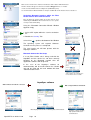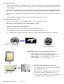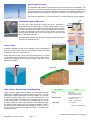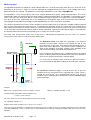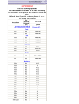
1
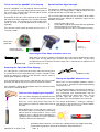
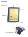
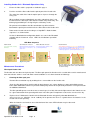
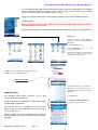
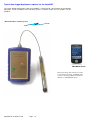
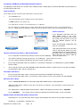
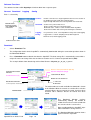
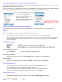
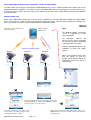
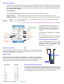
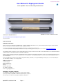
Geotechnical Instrumentation
User Manual & Deployment Guide
For the AquaBAT Water Level Recording Instrumentation
AquaBAT 17.5 and 22 mm diameter models
Download the AquaBAT Guide at
http://www.aquabat.net/downloads/Aquabat-user-guidev104.pdf
Last updated July 2012
WHAT WE PROVIDE
WARRANTY PROVISIONS
Keynes Controls Ltd . warrants the AquaBAT range of loggers and Bluetooth interface for one year from date of purchase by the end user against
defects in materials and workmanship under normal operating conditions.
To exercise this warranty contact Technical Support at the phone or e-mail address listed below
for a return material authorization (RMA) and instructions. Complete warranty provisions are posted on our website at http://www.aquabat.net
The information in this document is subject to change without notice. Keynes Controls Ltd . has made a reasonable effort to be sure that the information
contained herein is current and accurate as of the date of publication.
Keynes Controls Ltd. makes no warranty of any kind with regard to this material, including, but not limited to, its fitness for a particular application. Keynes
Controls Ltd will not be liable for errors contained herein or for incidental or consequential damages in connection with the furnishing, performance, or
use of this material.
In no event shall Keynes Controls Ltd . be liable for any claim for direct, incidental, or consequential damages arising out of, or in connection with, the
sale, manufacture, delivery, or use of any product.
HOW TO CONTACT US
Technical Support
Keynes Controls Ltd
Riseley Business Park
Riseley
Berkshire, RG7 1NW
Tel: (0044) 118 327 6067
E-mail: [email protected]
FIRMWARE & SOFTWARE UPGRADES
The AquaBAT is upgrade able. Contact Keynes Controls Ltd. for details.
If you suspect that your AquaBAT is malfunctioning and repair is required,
you can help assure efficient servicing by following these guidelines:
AquaBAT User Guide V1.04
Page 1
Table of Contents
Page No.
3
4
5
6
Fibre Cable Installation
Preparing the Fibre Optic Cable
Attaching the Fibre Optic Cable AquaBAT
O-ring Specification
Preparation & Termination fibre into Header unit
Stand-alone Deployments
AquaBAT deployed at the Bottom Bore Hole / Stand-pipe
Fixed Level installation
Test to see that the AquaBAT is Functioning
Optimising Fibre Signal Strength
Protecting the Fibre Cable ends when not in use.
Storing the AquaBAT when not in use
Take care when deploying the AquaBAT
7
Bluetooth Header Unit
Fibre Termination Cap
8
Installing Header Unit - Bluetooth Operations Only
LED Boot Sequence
Maintenance Procedures
9
Activating Bluetooth Fibre Header Unit In Microsoft Windows Mobile 6.0
10
Bluetooth Connection Not Setup
11
Care of the Fibre Cable
Care of the AquaBAT Logger Unit
Replacing the battery in the Bluetooth Header Unit
AquaBAT Battery Replacement Service
12
Operating Environment
Terminating Cable for Man holes
Pump Testing
Water Table & Ground Water Flow Monitoring
13
Measuring Level
Reference Level
Typical data logger deployment options for the AquaBAT
Smart Phone / PDA Options
14
15
16
17
18
19
20
21
22
23
24
25
AquaSync Application Software
List of files
Software Download
Loading software into a PDA/ Mobile Phone
Software Windows
Start-up Sequence
Connection to the AquaBAT Water Level Recorder
Signal Strength - Fibre Connection.
Assigning a COM port for Bluetooth Communications
Failure to Connect
Common Communication Errors- Bluetooth Network
Fibre Optic Cable Errors
Bluetooth Device Name
Multiple Header Unit Bluetooth Network Identification
Software Functions
Downloads
Clearing the AquaBAT Memory by Resetting the Data Recording Files
Config - Assigning Instrument Configuration Details
Configuration Parameters - Assign Instrument Name, Assign Location
Data Recording Operations
Starting Data Recording
Fibre Header Bluetooth Operations & Problems Trouble Shooting Guide
Alarm Level Recording
Confirm Parameters / make Changes
Alarm Reference Levels
Reference Point
Duration of Data Recording Table
Data File Format
Spread Sheet Data Import
Synchronising the Internal Clock / Setting the Time Zone
Equations used to Determine Water Level
Gravity Variations with Latitude
How to determine local values of gravitational acceleration and altitude
Making a level measurement
Local Gravity Values
Transient Protection
Theory of Operations
Faraday cage
Why use Fibre Optic Communications
AquaBAT User Guide V1.04
Page 2
Fibre Cable Installation
The fibre cable installation instructions are the same for both the AquaBAT sensors and Bluetooth header units.
Fibre Port
AquaBAT User Guide V1.04
Page 3
Preparing the Fibre Optic Cable
Fitting the fibre optic cable into the AquaBAT or into the Header unit does not require any specialist
tooling or prior knowledge in the use of fibre optic cabling. In order to use it cut the cable to the correct
length, allowing a few metres of spare cable in case the ends become damaged, and strip the outer
sheathing away as specified for the instrumentation.
The fibre optic cable is constructed in 2 parts and consists of an outer protective sheath and an inner
plastic core. The outer sheath is 2.2 mm in diameter and the solid plastic core is 1 mm in diameter.
Cut the sheath away exposing the solid plastic inner core. Simple wire strippers are more than
adequate for this operation. When using the more expensive strippers set the stripping depth to no
less than 1 mm.
0
5 mm
Important Note. Take care that the end of the fibre is clean cut and is perfectly flat.
Termination for connection
to Header unit and sensor
Optical edge cut at an acute angle will degrade the
signal transmission through the fibre.
Fibre cable cut with a
flat optical edge.
Attaching the Fibre Optic Cable AquaBAT
1.
Ensure that the O-ring is seated firmly into the space at the top of the AquaBAT.
Failure to do so may mean the fibre comes loose and disconnects from the instrument.
2.
Slide the plastic termination cap onto the fibre cable through the central alignment hole
3.
Check that the optical edge of the fibre optic is clean before inserting into AquaBAT.
4.
Push the optical cable into the central hole in the AquaBAT until it goes no further. See below.
5.
O-ring
O-ring Specification BS005V75
Viton 75 shore hardness
Slide the fibre termination cap down the fibre until light pressure is put onto the O-ring and align up
the fixing holes in the cap to to screw holes in the top of the instrument.
Fasten the cap to the instrument using the 2.5 mm mounting bolts. Take care to fit the screws as
opposite pairs. Tighten the screws until the o-ring firmly grips the fibre cable.
Testing the Fibre Cable
Observe the free end of the cable unattached to the instrument and this will glow briefly. The better
the fitting of the fibre into the AquaBAT the brighter the flash observed at the opposite end.
Fibre Optic cable connected
to the AquaBAT Unit
2.5 mm
Preparation & Termination fibre into Header unit
NP_Header Unit - Fibre Optic
Interface
1.
Check that the optical edge of the fibre optic is clean before inserting it into the Header unit.
2..
Push the optical cable into the central hole of the fibre port on the Header unit. (See opposite)
The fibre cable is gripped and held into place by the retaining o-ring contained in the entry port.
Once the cable is attached to the Header unit the AquaBAT data communications can take place.
Mounting Bolts
AquaBAT User Guide V1.04
When the fibre optic cable is not being used fit the protective plastic cap to keep
the end clean.
Page 4
AquaBAT Deployment Manual Version 3 Sept 2009
Maximum Fibre Cable Length = 100 m
The photo opposite shows the fibre about to be fitted into the
AquaBAT. The O-ring seal must already be fitted before the
cap can be screwed into place. Once the termination cap is
screwed into place the cable is attached to the instrument.
Take care to fit the screws in opposite pairs and tighten such
that the cap fits flush to the top of the AquaBAT.
O-ring
View looking into fibre port
on the AquaBAT
Stand-alone Deployments
Data Download
O-ring Specification BS005V75
Viton 75 shore hardness
AquaBAT deployed at the Bottom Bore Hole / Stand-pipe
This is the simplest of the deployment options for the AquaBAT and it is simply a
matter of connecting the instrument to the fibre cable and deploying it down the bore
hole. Once the AquaBAT is at the bottom of the hole simply lock off the cable gland
and cut the fibre to suit the location. Fit several of the star washers to the cable above
the cable gland to prevent the cable end from slipping.
Alternatively, simply cut extra cable and terminate securely to the inside of the well
head or on the man hole. floor. Fit the plastic cap to the end of the fibre cable when
not in use to keep the cable head clean.
Clean the Fibre end before insertion into the Header interface. Simply run the fibre
under water or wipe with a cloth. Some moisture on the fibre when inserted into the
Header unit or AquaBAT will have no affect on its operation.
Fixed Level installation
This is the most common method of deployment for the AquaBAT.
For this type of deployment it is recommended that the fitting of a fixed position
deployment bar (see opposite) is used to take the strain of the instrument when it
is deployed, and to re-position the sensor should it be removed for maintenance.
A Carabeana is attached to the bar and the Fibre cable is wrapped around it a
number of times to prevent it slipping. The AquaBAT is deployed below the fixing
bar to its permanent position. So long as the cable gland is tightly fastened and the
star washers are attached to the excess cable then the sensor will be permanently
placed and the results will reliable.
No special care needs be taken to protect the fibre cable that protrudes from the
top of the bore hole cover. When not in use fit the protective plastic cap onto the
end of the cable.
Where possible and when long term deployment is going to be carried out leave
the excess cable in the top of the bore hole cover or man hole if one is available.
The cable is plastic and so is safe from corrosion.
AquaBAT User Guide V1.04
Page 5
Data Download
Fixing Bar
Multiple Turns
of fibre cable
secured around
carabiner.
Test to see that the AquaBAT is Functioning
Optimising Fibre Signal Strength
Direction of fibre
Since the AquaBAT uses only light for data transmission The AquaSync software used by all of the the AquaBAT range
then it is possible by simply looking into the optical port, of of sensors uses an scaling factor 0 - 1800 to indicate the level
the sensor or the end of the fibre connecting to the header of light signal being received from the sensor.
unit, to see if data is being sent.
The received signal strength level has to above 40 for reliable
Examination of the fibre cable attached to the AquaBAT communications to be undertaken. Should the signal level be
will show a brief flash of light when the instrument attempts below this level then:
to communicate. The signal flash is just observable to the
naked eye and is a clear indication that the instrument is 1.
Clean the fibre cable ends
operating.
2.
Reduce fibre length to shortest possible for application
3.
Replace battery in the Header unit.
An instrument under normal operation the flash rate is 1 4
Check that the fibre has been cut and fitted correctly.
every 30 seconds.
Direction of fibre
Brief comm's
signal flash
Scarple or
sharp scissors
Illuminated LED
in fibre optical port
Protecting the Fibre Cable ends when not in use.
Protective Cap
When not in use Keynes Controls recommends that a cover/cp be fitted onto the end of
the fibre cable. The cap will keep the end of the fibre clean and so make sure the signal
strength between the instrument and the header unit is maintained at its optimum level
when the cable is re-used.
Protecting the Fibre Cable From Slipping
If a cable gland is used to prevent the fibre cable from moving once
an instrument has been lowered into place. Keynes Controls recommends the fitting of a number of Star Washers onto the cable as
shown opposite above the gland.
Star Washer on fibre
Storing the AquaBAT when not in use
If the gland becomes loose the the cable will only slip to the position
When not in use the AquaBAT should be stored in
of the washer and this will ensure that the instrument is not lost.
its case or on a shelf with the optical port pointing
If the AquaBAT is deployed to the bottom of the bore hole or tank then away from the sun.
the washers need not be fitted.
As the AquaBAT loggers communicate by light it is
possible; however unlikely, that flickering sun light
Take care when deploying the AquaBAT
may accidentally start communications with the
device. Keeping the optical port dark / out of
Take care when deploying the AquaBAT that the possible light will prevent this event from
fibre cable is securely fastened to the instrument. happening. This will also optimise the battery life.
Raise the sensor slowly when lifting from the The storage temperature is - 30 deg to + 50 Deg C
water and try to avoid and sudden movements of and so long as the instrument is maintained within
the cable.
these limits its long life is assured.
When lowering the sensor into place make sure
that the fibre cable is free from twists and unwinds
from the drum in a normal manner. Leave a small
amount of excess cable to make termination in a
appropriate place and allow for repairs should the
end of the cable become damaged.
The details in this document are correct at the time of printing. Contact your supplier for the latest
product details. Specifications and operations are likely to change without notice.
AquaBAT User Guide V1.04
Page 6
Bluetooth Header Unit
Fibre Optic
Cable Port
Battery
Battery Supply: 2 x AA Cells
Protective Plastic
Boot Cover
Power On/Off
Front View
Fibre termination cap
View into fibre optic port of the header unit
with the fibre securing block attached.
AquaBAT User Guide V1.04
Page 7
Installing Header Unit - Bluetooth Operations Only
1.
Ensure the fibre cable is prepared as detailed in page 3.
2.
Push the end of the fibre cable into the optical port of the Header unit.
The end of the cable clicks into the optical port as it passes through the
o-ring seal.
When multiple instrument downloads are to be undertaken there is no
need to fasten the fibre optic cable into the Header unit permanently. The
friction grip provided by the O-ring will give satisfactory results.
For permanent installations the fibre termination cap will need to be
fitted onto the optical port and this locks the fibre cable to the Header unit.
3.
Fibre Optic cable fitted into Header Unit
Power on the Header unit and so long as a AquaBAT is fitted the boot
sequence is as shown below.
As data is downloaded or configuration details are sent via the Bluetooth
network and the instrument status LED’s flash indications operations
underway
LED Boot Sequence
Initial Power On
Start a Bluetooth Connection
Made a Bluetooth Connection
Data Transmission
Green Power LED constantly
illuminated
Bluetooth LED status indicator flashes
when making a connection to the
Header unit.
Bluetooth LED status indicator is now
permanently illuminated.
The Red Fibre Tx LED and Yellow Fibre Rx LED flash when data
is being sent from the AquaBAT. When large amounts of data
are being downloaded then the Red Fibre TX and Yellow Fibre
Rx LEDs may appear to be permanently illuminated to the eye.
Flashing LED
At slow sample rates when observing real-time
data the individual Rx and Tx status LED switch
on and off slowly.
Maintenance Procedures
Fibre Optic Header Unit
The Header units are robust and splash proof . The fibre optic port of the Header unit is a sealed device and is manufactured
from 316 or better stainless steel and under normal conditions is safe from corrosion and damage.
1,
Cleaning the fibre optic port.
Remove fibre termination cap by undoing the 4 x 2.5 mm bolts on the header units
Clean the fibre optic port by washing with de-ionised water, or if serious fowling use water with mild detergent.
and a cotton wool bud to remove any material. Allow plenty of time for the port to dry out before re-using the Header
for additional downloads.
The fibre port will operate even when wet as water ingress has little effect on the light transmission. Note there can
be signal attenuation when operating with water in the fibre port. For optimum results make sure the unit is dry.
2.
Replace the 2 X AA batteries fitted inside the Bluetooth Header unit typically after 500 downloads or
after excessive use. Should a sensor suddenly fail to operate then there is a good chance the batteries in the
Header unit needs replacing.
When the batteries are low then unusual behaviour of the status LED indicators may be observed.
AquaBAT User Guide V1.04
Page 8
Activating Bluetooth Fibre Header Unit in Windows Mobile 6
The instructions below show how to install the fibre Header unit on to a Bluetooth wireless network
used in a Windows Mobile 6 operating system. The operating system can be part of a mobile
phone, PDA or any other similar communications device.
Details can change without notice. Refer to your operating system manual additional details.
Important Note
Before attempting to use the fibre header unit ensure that the Bluetooth interface in the PDA
or mobile phone is switched on.
Carry out this operation for each individual Fibre Header unit being used by the recording device.
Instructions
Using the ‘Settings’ option within the
operating system. The following Windows
will appear.
Select ‘Connections’ Tab
icon
Select
‘Bluetooth’
configuration operations.
to
start
The Windows Mobile 6 will show Windows
similar to to those opposite while
configuring a Bluetooth device.
Activate the Bluetooth Manager to Add the Fibre Header
unit Bluetooth to the PDA/Mobile Phone.
Bluetooth Manager
A Window similar to this one will appear.
Other devices such as hand free or Sat
Navigation systems may have icons that
appear here.
Important note
The AquaBAT Fibre Header unit does not use data
encryption for data transmission.
Select ‘New’ Tab
Select’ Explore a Bluetooth Device’
Remove any data encryption options for the Fibre Header
unit Bluetooth configuration.
This will not effect any encryption used by any other
device used by any other Bluetooth device and is only a
feature of this device.
Windows Mobile 6 sets up encryption for use with the
header units by default. This has to be removed for reliable
operations.
AquaBAT User Guide V1.04
Page 9
to operate a new Header unit.
Make sure the Header Unit is switched on and that the Power Status LED is illuminated.
The Fibre Header unit appears under the icon labelled ‘Blogger-n’ where n = number
of units associated with the data recording device (PDA/Mobile phone)
See “Communications Wizard” window for example of a PDA with 3 Fibre Header units associated to it.
Activating Bluetooth Interface within the Fibre
Header unit for data communications
Once the Bluetooth interface within the Header unit has been
identified by the PDA/Mobile Phone then it has to be set to operate
correctly for data downloading.
Using the “Bluetooth Connection Wizard” Window
opposite simply
1. Select ‘SPP’ option within the “Service Selection”
list
2. Disable the ‘Security’ Tab
Select ‘Next
‘ option at the bottom of the Window
The operating system will respond ‘Shortcuts
Created’ once the process is completed.
The new Header unit will now operate with the
AquaSync software.
Bluetooth Connection Not Setup
If a new Fibre Header unit is being used with the
AquaBAT and this device has not been correctly
identified by the Bluetooth network then the
applications software will not operate.
In the case of the AquaSync software no
communications will be made between the Header
unit and the PDA and the main window will show
“Communications Error”
AquaSync software window
when no Bluetooth communications
from the Header unit is available
AquaSync software
With no Bluetooth network connection
With configured Bluetooth Network
Initial AquaSync window when initialising data communications.
AquaBAT User Guide V1.04
Page 10
AquaSync software showing
fully operational Bluetooth
communications
Care of the Fibre Cable
The fibre cable should in fact be trouble free as it is safe from corrosion and cannot be damaged by lightening
strikes. Some wear and tear at the ends of the fibre where it is terminated into the AquaBAT and into the Header
unit is expected.
3.
After a successful deployment remove the bolts holding on the fibre termination cap from the AquaBAT take out the
fibre. Check the end of the fibre for wear and signs of stress damage due to the pressure asserted by the O-ring.
Should and stress damage be observed simply cut back the fibre and re-fasten onto the sensor. See details on
page 3.
Cut back the fibre as described on page 1 and re-attached the cable when necessary.
Care of the AquaBAT Logger Unit
After a successful deployment the AquaBAT should be cleaned before being re-used.
Make sure the Fibre termination cap is removed before cleaning.
Remove the O-ring from the fibre entry port
4.
Wash the AquaBAT in fresh water to remove any contamination on the case.
Clean the optical port to remove any signs of accumulated dirt in the optical port.
Use a mild detergent and cotton wool bud to remove any contamination and material build up in the fibre port.
O-ring
Fibre termination cap
Replacing the battery in the Bluetooth Header Unit
1
1.
2.
3.
4.
5.
3
2
Remove the Header unit from the protective plastic boot cover.
Slide the battery access panel off the case and lift out the old AA batteries.
Fit the new battery onto the connector and fit the cover plate
Switch on the Header unit using the On/Off button. The Power status green
LED will illuminate.
Fit the Header Unit back into the protective plastic boot cover.
AquaBAT Battery Replacement Service
The AquaBAT has to be returned to Keynes Controls for
a new battery to be installed.
Battery Compartment
Cover
Rear of Header Unit
Special tools are required to remove and install the
battery and this cannot be undertaken by the User.
All sensors are re-calibrated after a battery replacement
is carried out. There is a charge for this service.
AquaBAT User Guide V1.04
Page 11
Operating Environment
The AquaBAT will function satisfactorily in the worst of environmental conditions. The
instrument is of solid construction and does not use any vented signal cabling which is
the main point of weakness due to corrosion causing leaks for competitive products. For
inland water ways the AquaBAT is supplied in a stainless steel 316 or better casing.
For salt water applications a Titanium enclosure version instrument can be supplied.
Vent
Terminating Cable for Man holes
The fibre optic cable linking the header unit to the AquaBAT is
deployed with greater length than is actually required and the excess
is looped and stored at the bottom of the man hole. For best operation
maintain several meters of cable is left at the bottom of the man hole
to enable the operator to easily fit the Header unit into a convenient
location when required. Take care to fit the plastic cap over the end
of the cable when not in use.
Should the fibre cable become damaged simply cut back and strip the
sheathing as detailed on page 1.
Man hole
Fibre Optic
Cable
Overburden
Impermeable
Layer
Pump Testing
Setting the AquaBAT to high speed recording, and using it deployed
with a in-situ bore hole pump the characteristics of the water flow
around the pump can be determined .
Water
Bearing
Layer
Along with pump testing, impulse water level interaction can equally
be monitored using the AquaBAT. The water level readings can be
seamlessly integrated to the pump operations and water levels
against time plotted.
AquaBAT
Logger
Bore Holes
B
A
Water
Table
Capillary Fringe
Flow of ground water
Typical Pump Test Water Flow
Water Table & Ground Water Flow
Water Table & Ground Water Flow Monitoring
Using a number of bore holes at widely spaced locations and the
ability of the AquaBAT to synchronise data by virtue of its use of its
temperature compensated clocks offer high stability. It is possible
to monitor the water table levels across defined land masses and
to get some indication that water flow is taking place by the change
in water temperature. The ability to take reading from a series of
locations enables the water table gradients to be followed through
the different perm abilities of the local ground conditions. With a
well planned and maintained water monitoring system effects on
the water table can be observed due to changes caused by local
building operations.
Description
Notes
O-ring
BS005V75
Viton 75 shore hardness
Outside diameter 5 mm
Mounting Bolts
2.5 mm Hexhagonal head
Thread size: M3
Height, external:10 mm
Cable Gland
2 - 5 mm Brass
Table of Consumable Parts
AquaBAT Deployment Manual Version 2 Sept 2009
AquaBAT User Guide V1.04
Page 12
Measuring level
The AquaBAT determine the height of a water column above the sensor by measuring water pressure. A version of the
AquaBAT set to measure a range of 1 bar but calibrated to record barometric pressure is used available when local
barometric levels are required. The barometer version of the AquaBAT has part number AquaBAT-bar.
The AquaBAT is a very accurate device and can be setup to allow for local gravity, salinity and temperature. The sensor
automatically allows for varying temperature when taking a reading and storing data. The AquaBAT is an intelligent sensor
and as such can return water level data in a number of different engineering units. The output values from the AquaBAT
have to be in the same engineering units as the barometer for the optimum water level measurements to be achieved.
Typically both the AquaBAT level recorder and the AquaBAT-bar use units of mH20 for stored data.
The compensated water level values can be related to a reference point such as the top of the standpipe tubing at ground
level, or some other convenient reference level. To undertake this operation and in the event that the exact length of the
fibre cable being unknown, the distance between sensor head and the desired reference point needs to be measured and
can be manually entered into the Connect software during a download. Typically the initial water height as measured from
the top of the bore hole head using a water dip meter is used as the reference point.
Fibre-optic Cable
The water level measurement made using a dip meter is independent of barometric pressure and is an absolute
measurement. This makes it an ideal reference datum point.
Borehole Head
Datum
Barometer
The Reference Level used within this application is the distance
manually measured from a Datum level, normally the top of the
measuring tube to the water level obtained independently using a
water level meter (Dip-meter). The reference point establishes the
depth of the AquaBAT and allows readings of the AquaBAT to be
converted into readings referenced to the Datum level.
HDepth-to-water
If the elevation of the Datum level is established relative to national
datum ( Ordnance Datum or Port Datum) then water levels from other
wells can be compared related to a common datum.
It is necessary to record the time at which the Reference Point is
measured so that the AquaBAT reading can be used at the same time.
Water
Level
Reference
Level
HReading
HCable
An AquaBAT-bar barometric logger is used to measure the air pressure
variations for every measurement area. Typically only a single sensor is
needed for each 20 km2 area. Compensation for these air pressure
variations can be made quickly and efficiently using the Connect Logger
software package.
Sensor
Level
Example:
HDepth-to-water = Depth to water ( Reference Point) = 15.62 m
HReading = AquaBAT Reading = 10.52
Calculated depth of AquaBAT relative to Datum Level
= 15.62 + 10.52 = 26.10 m
This value of 26.10 is used to calculate Depth to water subsequently
e.g. AquaBAT reading = 5.10
Depth to water relative to Datum Level = 26.10-5.10 = 21.00 m
The Reference point should be re-established on a routine basis to ensure quality assurance by an independent means of the verification
of the data. Additionally, correct use of the Reference point will improve accuracy of readings, particularly at high pressure heads on the
AquaBAT.
.
AquaBAT User Guide V1.04
Page 13
Typical data logger deployment options for the AquaBAT
The image below demonstrates how the AquaBAT is connected to a data logger for stand-alone
operations. Fixed installation data recording systems or GPRS remote access solutions can be
provided.
Bluetooth-Fibre Header System
PDA/Mobile Phone
The follow image demonstrates how data
is downloaded from the AquaBAT water
level recorder using a Bluetooth cable free
interface to a PDA/Mobile phone
AquaBAT User Guide V1.04
Page 14
Smart Phone / PDA Hardware
A sample list of PDA /Mobile Phones suitable for running the AquaBAT applications software is:
Hewlett Packard
HP iPAQ Models HW9615, RW6815, HX2190, RX5935, HX2750
HW6510, HX2100, HX4700, RX5720, HW6910
Motorola
Q9, Sidekick,
HTC
HTC S620, HTC P6500. HTC P3470,
HTC P3600, HTC Advantage
The minimum specification for operating the AquaSync application software on any Smart phone or PDA is:
Windows Mobile 5.0 or greater operating system. 320 x 240 Graphical Colour screen - Touch sensitive (ideal)
AquaBAT User Guide V1.04
Page 15
AquaSync Application Software
The following pages describe the installation and use of the AquaSync application software used with the AquaBAT range
of water level recorders.
List of Files
The software consists of a single file:
AquaSync.exe
Software Download
The AquaSync software is freely available and is downloaded from
http://www.aquabat.net/software/AquaSync.exe
http://www.aquabet.net/software/AquaSync.zip
Loading software into PDA / Mobile Phone
The simplest way to download the AquaSync software into a PDA/Mobile phone is to use a device with a built in GPRS
modem or WiFi interface from a Hotspot and to download the software directly from the Keynes Controls web site. Save the
Download and activate to run.
Download the AquaSync.exe file and store it to a suitable Flash memory card. Fit the memory card in to the PDA/Mobile
Phone and activate the software from here. Use the Flash Memory card to provide additional storage for data downloads
from the instruments. Refer to the product User manual
Software Windows
The images below show the different Windows presented to the User from within the AquaSync software. All the operations
required to operate a AquaBAT water level logger are shown below:
The default Window once the AquaSync software is initiated is the “Connect” Window. It is from
here that communications to the instruments is started.
Selection of the additional Windows is simply by selecting the Tabs at the bottom of the screen
The Instrument configuration details are displayed once communication is made to logger.
Connect Window
Use the Tabs at the bottom of
each Window to navigate
through the software.
Make sure that an instrument is
connected to the Header unit in
order that the Green indicators
shown opposite are activate.
The screens can look different if
running the software with no
logger fitted.
AquaBAT User Guide V1.04
Download Window
Page 16
Logging Window
Config Window
Software Start-up Sequence
The following images show the sequence the Status indicators on the PDA software follow when connecting to the
AquaBAT water level recorder via the Fibre Optic Header unit to a PDA/Mobile phone for data down loads and/or
Configuration changes.
Connection to the AquaBAT Water Level Recorder.
1.
Ensure the fire optic cable is connected from the AquaBAT into the Header unit.
Power on the Header unit and observe the green LED status indicator flash showing that the battery within the unit is
of a suitable level for operations.
To connect to a AquaBAT water level logger Select “Connect Tab” from with AquaSync software. The sequence of
images below will be displayed automatically as communications to the AquaBAT is activated communications to the
Header unit and AquaBAT are made.
Initial Screen - No connection
Bluetooth connection made
and communications started
Bluetooth communications
operating and communications
to the AquaBAT initialised
Full communications to
AquaBAT across the Bluetooth
interface
Initial signal strength indication
being made
The signal strength indicator
shows the received signal
strength at maximum level
(100%)
Signal Strength - Fibre Connection
The signal signal strength indicator is only provided as an aid to show how well the fibre optic cable has been connected to
the instrumentation and used as a guide only. Communications can be carried out reliably with a signal strength indicator
value above 20.
So long as Status indicators on the Connection screen are both green then communications can be reliably carried out.
Status Indicator
Bluetooth Cable
Free network
Status Indicator
Fibre Optic Connection
Fibre Optic Signal
Strength Indicator
Connect Tab
Copyright AquaBAT 2011-2012
Keynes Controls Ltd with holds the right to change the specification without notice.
AquaBAT User Guide V1.04
Page 17
Assigning a COM port for Bluetooth Communications
The following section details the selection of the COM port within a mobile phone or PDA for Bluetooth Communications to
the Fibre Optic Header unit.
Initial Setup Only
For the initial operation of the Bluetooth network with a Header unit only.
1.
Select “Connect” Tab
Select the COM port from the available list in the drop down box.
For PDA operations select Ports 6 or 7.
For mobile phone selection - refer to Manufacturers User Manual.
Once the COM port is identified and associated with the Bluetooth communications then it is stored automatically for
later use. Simply activate the AquaSync software from the File manager and the port should automatically be assigned.
Failure to Connect
If the Bluetooth connection from the
PDA/ Mobile phone is not set-up
correctly then any attempt connect into
the Header unit will not be successful
and the Window opposite will be
displayed.
COM port selection
Check the Bluetooth configuration and
retry the connection.
Connect Window
Failure to Connect Window
Common Communication Errors - Bluetooth Network.
If it is not possible to communicate with the Header check the following:
Low signal power often means the fibre
cable is not correctly fitted or the ends
are badly finished. It is important that the
fibre optic cable is accurately terminated
with a flat clean cut edge to allow for
maximum light transfer.
1.
The batteries within the Header unit are low. 2 x AA Batteries - replace where necessary.
The green power indicator LED will flash when the Header is powered on.
2.
Ensure that the Bluetooth cable free network is associated to a COM port - See Manufactures guide for Mobile
Phone or PDA
3.
Ensure that the Header unit and PDA/Mobile Phone Bluetooth network are within range of each other and within
the operational range which is typically 10 m.
Fibre Optic Cable Errors
1.
Ensure that the Fibre optic cable is correctly terminated into the AquaBAT and Header Unit.
Ensure that the Fibre optic cable is cut correctly so it fits flat to the sensor in the Header unit and AquaBAT.
Bluetooth Device Name
Select “search new devices” on Connection option within Mobile Phone / PDA applications.
Allow the mobile phone / PDA to search for a new device in exactly the same procedure used to connect to a
Hands-Free sets.
The mobile phone / PDA Bluetooth communications software will identify the Header unit as “AquaBAT”
Select “AquaBAT” -- The Header unit has now been identified and communications can be carried out.
Multiple Header Unit Bluetooth Network Identification
Should there be several header units within range of the Bluetooth connection then they will be identified as
AquaBat N
eg AquaBat1 , AquaBat2 etc ....
AquaBAT User Guide V1.04
Page 18
Software Functions
The software functions within AquaSync is broken down into 4 separate parts:
Connect Download
Logging
Config
Each is selected by
Connect -
Network Status
Indicators for Fibre
optic and Bluetooth
connections.
Enables connection to a single AquaBat instrument and selection of
the COM port for blue tooth data communications.
Signal strength indicator between the AquaBAT and Header unit.
Download - Set Reference point for water level
Shows real-time water level and temperature
Download status - number records available within AquaBAT
Shows file into which data is being stored during the download
Logging -
Re-synchronise clocks, Clear AquaBAT memory and restart logging.
Config -
Logger Name, Location, Sampling Period, Alarm high level
Alarm low level, Alarm logging period.
Software Selection Tabs
Download
1.
Select “Download” Tab
The configuration details for the AquaBAT is automatically downloaded during the connection operation shown in
the Download Window .
2.
Press “Download” button to obtain data from the AquaBAT. The data storage file is automatically created with a
unique file name consisting of the date and time of creation and s is Comma Separated format (CSV).
The example below shows data being archived into filename “blog2008_01_26_20_31_46.txt”
Reference Point (User Defined - Optional)
Communications Status
Indicators
Real-time Temperature (Deg C)
“Start Download” Button
Real-time Water Level (m)
Number Records Transferred
Data Download Filename
% of Records
Downloaded
Comma Separated Variable data file
The total number of records available for download is shown
in this Window. While the records are saved to file a real-time
counter indicates the percentage of records that have been
archived. 100 % indicates that the all records have been
stored.
Download Tab
The
Download
Window
updates
automatically showing the number of
records that have been archived and with
the current real-time sensor value.
Data recording within the AquaBAT stops
while information is being retrieved.
The Download Windows opposite show a
typical retrieval in operation.
AquaBAT User Guide V1.04
Page 19
Clearing the AquaBAT Memory by Resetting the Data Recording Files
The instructions below only refer to “deleting the data file within the AquaBAT” and this operation does not effect any other
configuration or parameter that has been set.
Care must be taken when performing this operation and it should only be carried out after data has been downloaded and
stored. Please carefully verify the data files are correct before deleting any data within the instrument.
Ensure that the Logging Window is selected.
1. Press the “Restart Logging” button
The Restart Logging Warning message
will appear as shown opposite.
Press the “OK” button and the data file is
deleted and reset to 0 Record size.
Take care when deleting data from
within the instrument as this action
cannot be recovered should the
memory be cleared.
Config - Assigning Instrument Configuration Details
The following sections details how to configure the AquaBAT for Data Recording and Alarm Level Data Capture.
Features
There are 2 independent modes of operation for the AquaBAT and these are:
1.
Data recording at a fixed interval in time - ie every second / minute / hour - Defined as Period
2.
Alarm Level Data Recording - Information can be gathered at a faster rate and in greater detail than the standard
data recording and can be activated only when the pressure / water level goes outside set alarm conditions.
Defined as Trigger
Configuration Parameters
Logger Name
Location
Period
Trigger
20 x Char
20 x Char - Can be any user defined parameter - Map Ref / name
Data Recording Period - 1s, 5s, 10s, 30s, 1 min, 2 min, 5 min, 10 min, 15 min, 30 min, 1 Hr
Alarm Level Period - 1s, 5s, 10s, 30s, 1 min, 2 min, 5 min, 10 min, 15 min, 30 min, 1 Hr
For call configuration operations
1.
Select “Config” Tab
and the “Config Window” below will appear
Assign Instrument Name
Enter the Instrument name in the box titled “Logger name” - to confirm press the “Set” button.
Assign Location
Enter the Instrument location in the box titled “Location” - to confirm press the “Set” button
Data Recording Operations
The instrument operates stand-alone and takes a new reading after a fixed time period.
Select “Period” box and a list of logging time periods is displayed.
Select a time period for the data acquisition operations and press “Set” button to confirm.
Example. To set the data recording at 1 min intervals select the “1 min” option.
Starting Data Recording
To Start Data Recording select the “Tick box” adjacent to the “Data Recording” menu option.
AquaBAT User Guide V1.04
Page 20
Fibre Header Bluetooth Operations & Problems Trouble shooting Guide
The fibre header unit needs to be connected to a downloading device such as a PDA or mobile phone before data can be
downloaded from the AquaBAT. This document covers Microsoft Mobile 6.0 version operating system only and meant as
a guide only. Other versions of the operating system will operate but may shows slightly different Configuration Windows
than shown below.
Multiple Header Unit
When using multiple Fibre Header units each one must be individually setup to the Bluetooth network in the PDA / Mobile
phone. For example if a PDA is being used to download information from a number of fixed installations at multiple sites
then each Header unit will have to be configured onto the Bluetooth network.
Stand-alone systems with their own
Fibre Header units.
Note
Windows Mobile
6 PDA / Phone
The Windows Mobile 6 operating
system is supported on a wide
range of products.
h
ot
to
ue
Bl
m
Co
Aquabat-1
Aquabat-3
ns
tio
ica
un
m
Bluetooth Instrument Names
The AquaSync software will
operate on any device supporting
this operating system and including
a Bluetooth data connection.
Common downloading devices for
AquaBAT at PDA and mobile
phones.
Aquabat-2
When using multiple Header units
then you should see each one
listed in the Bluetooth setup of the
PDA/Phone similar to the way it is
shown below.
Only when the Bluetooth interface on the Fibre Header unit is
correctly identified by the PDA will the AquaSync software
operate correctly as as shown opposite.
Details in this document can change without notice. Refer to the
PDA/Mobile phone manual for in depth operation of the Microsoft
operating system.
If the Bluetooth network is not setup correctly
then the above screen will be all appears upon
activating the AquaSync software.
AquaBAT User Guide V1.04
Page 21
Alarm Level Recording
The Alarm Level recording enables data to be acquired at a different rate to the standard data acquisition operation
when the water level exceeds pre-set conditions. When the Alarm Level data is recorded at a higher rate that the
normal data recording operations it allows the water level to be observed in greater detail and is ideal for pump tests
and monitoring flood conditions.
Alarm Conditions
The Alarm Level Recording is only active when both Low and high settings are defined.
Deeper Than (m)
- defines the level in m for which the water level must exceed before data is stored.
Shallower Than (m) - defines the minimum level that the water level must be less less than before data is recorded.
To activate Alarm Level Recording select the “Tick box” adjacent to the “Alarm”
menu option..
Ensure that the Alarm levels are defined before activating the Alarm Level recording,
Communications status indicators
These must be green for
Configuration to be undertaken.
AquaBat Name
The Window opposite demonstrates a
AquaBAT configured to record alarm levels
when the water level exceeds 12.5 m or is
less than 1.2 m at a sample period of 10
seconds.
Location
Alarm Level Recording
logging period
Data Recording
activation tick box
Alarm level high
Alarm level high
Alarm Level
Recording activation
tick box
Alarm Level Recording
logging period
Config Tab
Press Set Button
to store Config parameters
The normal data acquisition rate is shown to
be 5 seconds.
The “Tick” boxes for the Alarm Level and Data
Recording operations are shown selected.
Confirm Parameters / Make Changes
Once the Configuration parameters are set or
changes are made then they are only stored
permanently into the AquaBAT upon
activation of the “Set” button.
Con fig Window
Alarm Levels Reference
The figure opposite demonstrates how the alarm levels are configured when using
Alarm Level Recording. The alarm levels are based upon water level above the
sensor only and the units are set in metres.
Reference Point
Top Bore Hole
Reference Point
Shallow level alarm
The Reference Point used within this application is a distance measured from a
Datum level and this is generally used to fix a Bore hole height with respect to Mean
Sea Level. For local measurements the Reference Point is generally taken as the
initial level of the water below to top of the bore hole. See diagram opposite.
High level alarm
Time Period
Duration
1 s
5 s
10 s
30 s
1 min
2 min
5 min
10 min
15 min
30 min
1 Hr
55
11
23
69
138
277
694
1388
2083
4166
8333
AquaBAT User Guide V1.04
hrs
Days
Days
Days
Days
Days
Days
Days
Days
Days
Days **
Duration of Data Recording Table
The AquaBAT contains 200,000 records for data storage and has a operating
life of 10 yrs depending upon the number of downloads undertaken and the
sample rates being used. The table below gives the operating duration for the
pre-set logging rates to fill up the internal memory of the instrument .
Page 22
Data File Format
The files created by the applications software is in Comma Separated Variable (CSV) text format. The configuration layout
is shown below. CSV means that new data items within a line are separated by a Comma.
#Name=10bar-Sensor
#Location=swindon
#Ref Point=1.20000
Borehole Logger 0001
Time,Pressure,Temperature
Timestamp,Bar,Celcius
31 Jan 2008 14:06:20 +0000,0.179000,10.469999
31 Jan 2008 14:06:30 +0000,0.179000,10.500000
31 Jan 2008 14:08:10 +0000,0.179000,10.440000
Sensor Name
Deployment Location
Reference height
Instrument Serial Number
Column Titles
Engineer Units for the columns
Spread Sheet Data Import
The image opposite shows a sample of data imported
into the Microsoft Excel package.
Most modern applications software accept CSV format
data and the results can be easily tabulated and processed without any special software.
Synchronising the Internal Clock / Setting the Time Zone
The internal clock of the AquaBAT is very accurate and is temperature compensated.
Over time the clock can drift and may be reset by the User at any time.
By default the AquaBAT internal clock is set to GMT with no offset. Any offset due to operation in another time zone has to be applied to the instrument.
The following instructions demonstrate how to set the internal clock of the instrument.
1.
Ensure that the “Logging” Window is selected.
Press “Re-synchronise Clocks” button
The instrument clock will now be set to the clock of the PDA / Mobile Phone running the Connect software.
During the writing of any configuration information the instrument temporarily suspends the data logging
operations until the action is completed.
Adjusting the Time Zone
The Connect application software detects the internal time and date of the device running the software. Therefore
if a PDA / Mobile Phone is set to operate in a different time zone to the default setting of the instrument then the
new time will be uploaded upon selecting the “Re-synchronise Clocks” button.
Copyright AquaBAT 2011-2012
Keynes Controls Ltd with holds the right to change the specification without notice
AquaBAT User Guide V1.04
Page 23
Equations used to Determine Water Level
The following equations are used to correct the water level height for variation in Altitude, Temperature, Local changes in
Gravity and density of water.
Gravity Variations with latitude
Precise values of g (Gravity) vary depending on latitude on the Earth's surface. The standard acceleration due to gravity at
the Earth's surface is, by definition, 9.806650 m/s² (32.17405 ft/s²). This quantity is known variously as gn, ge (though this
sometimes means the normal equatorial value on Earth, 9.7803 m/s²), g0, gee, or simply g (which is also used for the
variable local value).
Pressure = . g .h
where
= Density Kg/m3
g = Gravity m/s2
h = Height of fluid column in m
How to determine local values of gravitational acceleration and altitude?
The variation in the value of g across the earth's surface is about 0.5 % due to latitude, plus a change of approximately
0.003 % reduction per 100 m altitude. Local topography and tidal forces also can have small effects.
An approximate value for g, at a given latitude and height above sea level, may be calculated from the formula:
g = 9.780 327 (1 + A sin2 L - B sin2 2L) - 3.086 × 10⁻⁶ × H m·s-2
where A
B
L
H
ge
=
=
=
=
=
0.005 302 4
0.000 005 8
latitude
height in metres above sea level
Equatorial value gravity = 9.780327 m
Reference UK National Physical Laboratory
http://www.npl.co.uk/mass/faqs/gravity.html
The AquaSync software is preset to use ge = 9.780327 (Equatorial) value of gravity by default, however a more accurate reading can
be determined by adjusting the default value of g to suit the values shown at the locations in the table below.
If the sensor variation in altitude from the locations below is known then reduce the listed value by 0.003% per 100m increase in altitude.
Making a level measurement
Level = mH2O pressure at 4 C
The corrected level measurement is
*
1
Density of water
9.80665
Local Gravity
Density (fresh water) = -6.017777E-6t2 + 0.000041t + 0.999841
and t = temperature in C
where density of water is defined as
Local Gravity Values
Amsterdam
9.813 m/s²
Istanbul
9.808 m/s²
Paris
9.809 m/s²
Athens
9.807 m/s²
Havana
9.788 m/s²
Rio de Janeiro
9.788 m/s²
Auckland, NZ
9.799 m/s²
Helsinki
9.819 m/s²
Rome
9.803 m/s²
BangkoK
9.783 m/s²
Kuwait
9.793 m/s²
San Francisco
9.800 m/s²
Brussels
9.811 m/s²
Lisbon
9.801 m/s²
Singapore
9.781 m/s²
Buenos Aires
9.797 m/s²
London
9.812 m/s²
Stockholm
9.818 m/s²
Calcutta
9.788 m/s²
Los Angeles
9.796 m/s²
Sydney
9.797 m/s²
Cape Town
9.796 m/s²
Madrid
9.800 m/s²
Taipei
9.790 m/s²
Chicago
9.803 m/s²
Manila
9.784 m/s²
Tokyo
9.798 m/s²
Copenhagen
9.815 m/s²
Mexico City
9.779 m/s²
Vancouver, BC
9.809 m/s²
Nicosia
9.797 m/s²
New York
9.802 m/s²
Washington, DC 9.801 m/s²
Jakarta
9.781 m/s²
Oslo
9.819 m/s²
Wellington, NZ
9.803 m/s²
Frankfurt
9.810 m/s²
Ottawa
9.806 m/s²
Zurich
9.807 m/s²
AquaBAT User Guide V1.04
*
Page 24
Transient Protection
Why use Fibre Optic communications on buried sensors
Immunity to Microwave and RF radiation
Safe from lightning strikes by design
Corrosion proof design - Faraday cage Protection
No signal degradation with time
No electrical earth problems
Fast Installation - No need to hide cabling to protect communications and
power supply.
Simple Fibre Cable Installation - Only hex key and scissors required.
AquaBAT
The AquaBAT water level logger has advantages over any other similar devices or sensor
deployed using traditional copper wire for power supply and communications operations.
The advantages for using fibre optic plastic cable are:
Iso-voltage Levels
100 KV steps
Theory of Operation
Fibre Optic Cable
The drawing above shows the effect lightning hitting a
structure which is used to host instruments deployed
underground, or fitted into large structures using traditional
wire based communications and power supply arrangements.
Sensors deployed across a copper wire based network with
external power supply, can all be damaged by lightening or
the results made unusable by noise created by electromagnetic interference. Interference is often caused by mains
pickup or ignition noise from engines. When long runs of
copper cable are deployed they act as an antenna making the
cable very susceptible to this type of interference
Case forms
Faraday Cage
Why use Fibre Optic Communications
Faraday Cage
The enclosure surrounding the AquaBAT instrument
consists of a single solid piece construction body that when
completed with the top clinch plate forms a full conductive
path around the instrument. Any local potentiometric effects
caused by lighting strikes appears as the same voltage level
around the instrument and there is no chance for break
down as there is no potential difference. There is little
chance for damage to the instrument and no chance for
break-down of the fibre optic cable.
Fibre Optic Cable
The concentric lines shown in the above fibre represent
Iso-voltage levels at the instance of the lightening strike. Each
individual line represents a potential difference of 100 KV. A
cable that connects the instrument at the top of the bore hole
to the sensor at the bottom can in effect cross multiple
iso-voltage lines and so cause high voltages to appear across
the cable and sensor. These high voltages can break down
the cable isolation and destroy the sensor. Copper cable also
acts as a antenna and can very easily pick up local
electromagnetic interference and is a particularly difficult
problem to solve especially in long cable runs. There can be
no electro-magnetic pickup when using fibre optic cable.
Header
Unit
How to prevent damage
AquaBAT
Keynes controls prevent damage to the AquaBAT units by
using a solid fibre optic plastic cable for communication
and deployment. Plastic fibre does not conduct electricity
even if it takes a direct hit from lightening and therefore it can
never damage the logger unit.
AquaBAT unit deployment
using Fibre Optic Cable
and shows the instrument
electrically isolated at a single
electrical potential level
AquaBAT User Guide V1.04
Page 25