1
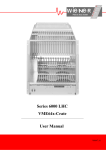
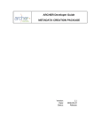
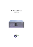
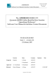
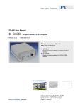
MDSR LIF for the Panasonic RF4800, RF4900, DR49, etc.
By Luke Snow, KJ6NWE
[email protected]
This extraction point should work for the RF4800 and RF4900 models. This installation puts the
LIF board inside of the receiver, drawing signal and power from the radio. The output signal is routed to
the back panel. No irreversible changes to the body of the rig were made, and only a few solder joints
were needed.
Please note that the output signal strength at the point listed below loads down the transistor.
It does not seem to detune, as readjusting nearby variable inductors doesn't improve gain. This didn't
seem to be a problem, however, as this radio has ample RF gain adjustability. See below, "IF Loading."
1.
Input Signal Connection (Figures 1-3)
a. Connect IF to signal to collector of Q32 (or, in RF4800 schematic, TR32).
b. Connect the shield to the ground side of neighboring C255 (the side nearest to the back
of the receiver).
2. Power Connection (Figures 1, 2)
a. Connect 12 volt power from the radio to the LIF board. This is near CP16. See the
photos, and use a volt meter to confirm location/polarity of the power connection.
3. Output Signal Connection (Figures 4, 5)
a. The version used for this installation was the RF4900LBS. This version of the RF4900 had
a jack in the back for connecting to a record/cassette player. This interface had screws,
and therefore (after a bit of soldering) could be bagged and taped away (no need to
remove it). Sheet metal was cut to size, with screw holes drilled out. Screws were put
through the holes, and a 3.5mm audio jack was put in place. Refer to the photos.
IF Loading
Without being connected to the LIF, the voltage output at the above extraction point was about
40mVpp for a strong local station. When connected to the LIF, the voltage output dropped to about
half, 20mVpp.
To remedy this, an op amp circuit would probably be the circuit of choice. Use a non-inverting op amp
with a gain of 0.5, or even less. I am still experimenting with the best gain to use, and this intermediate
buffer circuit is not yet shown in the figures below.
Service Manual: http://www.freeinfostuff.com/RF4800/RF-4800Service.pdf
Figure 1 – Top view
Figure 2 – Side view.
Figure 3 – Extraction point close up.
Figure 4 – Output port, modified for 3.5mm mono audio jack.
Figure 5 Inside-case view of 3.5mm jack. Stock components bagged and taped radio can be returned to stock configuration.