1
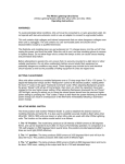
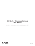
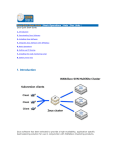
EINSTEIN
TM
Operating Instructions for EinsteinTM 640 Studio Flash
Every decade or two a quantum leap occurs in ideas and technology that sets the stage for years to
come. While most are content to follow the leader and add a feature or two, a few innovators take the
lead with revolutionary advancements that redefine the future state of the art.
Paul C. Buff, Inc.™ has a track record for such innovations, first in 1986 with the forerunner of the
modern self-contained studio flash – White Lightning™ Ultra. Then again in 2001 with the first full
featured affordable-yet-professional monolight for the new masses of young digital photographers –
the colorful little light that could – and did – AlienBees™.
We are now pleased to present the most advanced integrated studio flash system ever conceived – at
any price, with performance and features far beyond any “Professional” monolight. After two years of
intense design, evolution, blood, sweat, and tears, welcome to the brave new future of studio lighting
- Einstein™, and the companion Cyber Commander™ extreme integrated wireless control system.
Proudly designed and manufactured in America.
Paul C. Buff, Inc.TM USA offers a 60-Day Absolute Satisfaction Guarantee. If, for any reason, you are not satisfied with the equipment that
you have purchased from Paul C. Buff, Inc.TM USA, you may return your equipment within 60 days for a complete refund minus the cost of
shipping.
Paul C. Buff, Inc.TM USA additionally offers a 2-Year Factory Warranty on all EinsteinTM 640 flash units. The obligation of Paul C. Buff, Inc.TM is
limited to the repair or replacement of products that have become defective under normal use, as outlined in the manual. The warranty does
not apply to the flashtubes or modeling lamps as these become exhausted based on normal use (except in the unusual case of an unexpected
manufacturer’s defect). Should you experience any difficulties, please contact us so that we can assess your predicament and let you know if
we need to bring in your unit for repair.
Paul C. Buff, Inc.TM • 2725 Bransford Ave • Nashville, TN • 37204 • USA
1-800-443-5542 • 615-383-3982 • www.paulcbuff.com
v. 04/2012
CSXCV Transceiver (sold
separately)
Umbrella Holder
Slave Flash Sensor
Micro SD Card Slot
Function Button
Adjust Up/Down Buttons
8A Fuse
Power Button
Power Cord Socket
Test Button
Easy Set Button
Sync Jack (1/8-inch)
Quick-Release Levers
Swivel Ratchet Handle
Stand Mount
Tightening Knob
Frosted Glass Dome
Spring Clips
Holding Fingers
INITIAL SETUP: The Einstein™ flash unit ships with a black polycarbonate shipping cover,
in place over the flashtube and modeling lamp to protect these items in transit. The opaque
black cover must be removed before using the unit.
E640 with shipping cover
in place
Easy Set Button
Locate the Frosted Glass Dome (inside the box, packaged separately from the flash unit).
Place the dome on the faceplate of EinsteinTM by sliding the outer lip under the Spring Clips
one side at a time. If the fit feels loose, you may push in on the spring clips towards the
flashtube (be careful not to touch the flashtube), then re-attach the dome.
Place Einstein™ on a standard light stand (with 5/8” top coupler) inside the Stand Mount
and secure with the Tightening Knob. Loosen the Swivel Ratchet Handle to allow
swiveling Einstein™ up or down. Note the handle has a ratchet action. Pulling the handle
out from Einstein™ allows you to position it so that it doesn’t run into the body of the unit
when tightened.
Connect the supplied power cord into the Power Socket, and into a 120V or 240VAC,
50 or 60Hz outlet, or to Vagabond™. Einstein™ will automatically sense the voltage and
frequency. Press the Power Button to turn the unit on. Note that when Einstein™ is turned
OFF it’s actually in STANDBY Mode and can be turned ON remotely if it is fitted with the
optional CSXCV Transceiver and Cyber Commander™ remote.
EASY SET USE: The recessed Easy Set Button allows instant setup for most users.
Pressing this button clears any special programming and sets Einstein™ to the following
parameters (how the unit is shipped, with any programming cleared):
1. Modeling lamp tracks flashpower. The Einstein™ has “What You See Is What You Get”
modeling. Recycle indication is provided by an audible beep and by the modeling lamp
dimming then restoring brightness.
2. Einstein™ is placed in Constant Color Mode, the Slave Flash Sensor is turned on, and
the optional CSXCV Transceiver is set to Frequency 1 and Channel 1, if present.
Adjust Buttons
2
PRELIMINARY TESTING: With Einstein™ on, operating the Adjust Buttons should
increase or decrease both the flashpower and the modeling brightness by 1/10 f-stop per
click. If you hold either button in, the power will scroll.
DISPLAY FUNCTION: As you adjust the power using the Adjust Buttons, you should see
the Flash and Model Bargraphs on the LCD display go up or down correspondingly. Since
Easy Set defaults the modeling lamp to track the flash power, both bars should move in
Flashpower Bargraph (Full to 1/256 power)
Modeling Lamp Bargraph (0 to -8f)
Flash Adjustment Screen
Model Adjustment Screen
Model Lamp Mode Screen
Full Power ON
Tracks Flashpower
Independently Adjustable
Off OFF
Recycle / Ready Indicator Screen
Audible Indicator
Both
Visual Indicator
Neither OFF
Slave Eye Status Screen (slave on or off)
Action / Color Mode Screen
Remote Channel (channel 01 - 16)
Remote Frequency (frequency 01 - 16)
unison. If you press the Test Button at any power, the unit should flash and the modeling
lamp should dim. Then, when the unit is recycled, the modeling lamp will return on and the
audible recycle indicator beep will sound.
The same should happen if the Sync Jack is connected to your camera via sync cord to
your camera’s PC jack or Hot Shoe Adapter (see Camera Sync, page 8; see also CyberSyncTM / Cyber Commander™ Radio Remote).
Flash Adjustment screen
DEFAULT-TO-FLASH SCREEN: Einstein™ defaults automatically to the Flash Adjustment Screen after a few seconds following any setup changes; this is the screen with the
flash icon, highlighted in blue in the LCD screen diagram example (above). Power adjustment is performed by operating the Adjust Buttons. Notice as you change the flashpower
with these buttons, the blue-highlighted screen will display the current flashpower relative
to Full Power (-1.0f in this example), the color temperature (5725K in this example), the t.1
flash duration (1/2050 second in this example), the EU Number (5.7 in this example), and
the WS (320WS in this example).
Since the modeling lamp was set to track the flashpower by the Easy Set Button, the Model
Adjustment Screen will also change (-1.0f and 125W in this example).
Flash (left) and Modeling
(right) Bargraphs
ATTACHING LIGHT MODIFIERS: Light modifiers may be attached to Einstein™ via two
mechanisms: the Umbrella Holder or the front Reflector / Softbox Attachment Mechanism the Holding Fingers and Quick-Release Levers. The umbrella tube runs the entire length
of the top of the unit. It holds standard umbrella shafts up to 0.350” diameter, accommodating shafts 9mm and smaller. The Umbrella Holder tightening knob secures the umbrella in
the desired position. Reflectors, softboxes and similar accessories use the standard AB /
WL / Balcar mount, and are held securely by the Holding Fingers. Quick-Release Levers
are spring loaded and accessible from either side of the unit. Einstein™ mounts all accessories that fit previous Paul C. Buff, Inc.™ lights except the obsolete WL130, WL5,000 and
WL10,000 models. When mounting accessories to the face plate, be sure all four Holding
Fingers are within the opening and that the Quick-Release Levers have returned firmly to
the open position. Failure to do so can result in the unintended release of the modifier from
the light.
MICRO SD CARD SLOT: Firmware updates can be downloaded and installed via a standard
Micro SD Card plugged into this slot.
3
Model Mode screen
Model Adjustment screen
Recycle / Ready
Indicator screen
Slave Eye Status screen
Remote Channel screen
NAVIGATING EINSTEIN™ PARAMETERS: With the Easy Set Button, most simple
Einstein™ shoots are plug-and-play, not requiring parameter adjustments other than
flashpower. But for more advanced shoots, all parameters may be easily manipulated. The
display automatically defaults to the Flash Screen, identified by the blue background color
in the LCD screen example (on the previous page), where adjustments begin. The Flash
and Modeling Bargraphs are always present and indicate the power, relative to Full Power,
in 1/10f increments. As adjustments are made, the digital parameters in the Flash and Model
Adjustment Screens will update. To navigate the adjustment screens, pressing the Function
Button will sequence through all the screens. The currently active screen background will
turn blue. If no adjustments are made to the active screen for 10 seconds, the display will
revert to the default state with the Flash Adjustment screen active.
Flash Adjustment Screen (default): Adjust Buttons raise or lower flashpower at 1/10f per
click. Holding either button scrolls flashpower up or down. At any flashpower setting, the
digital numerical display in the screen and the left Flash Bargraph indicate all flash data. If
the model lamp is set to Tracking, the numerical model data and the right Model Bargraph
will also change.
Model Mode Screen: When this screen is active, you may select between four modeling
lamp modes by pressing the Adjust Buttons: On (Full Power), Independently Adjustable,
Track Flashpower and Off. When the modeling lamp is set to Track, there is a provision
in the Model Adjustment Screen to offset the modeling lamp brightness such that full
flashpower (640WS) results in a modeling brightness other than the default 250W. This
feature is useful when Einstein™ is used with other monolights and it is desirable to
maintain a constant ratio of model brightness to flashpower for accurate modeling previews.
For example, if an Einstein™ is used in a mixed system containing AlienBees™ B1600
units (640WS) with 150W lamps, it would be advantageous to set the Einstein™ such
that its model lamp also produces 150W when it is set to 640WS (see Model Adjustment
Screen).
Model Adjustment Screen: Selecting this screen allows modeling lamp adjustment in
either the Independent Adjustment mode or Tracking mode. In the Independent Adjustment
mode, the Adjust Buttons may be used to raise or lower the modeling brightness. The
digital display of watts and f-brightness relative to full 250W will update. In the Tracking
mode, operating the Adjust Buttons introduces an offset between flashpower and modeling
intensity. The bargraphs will still move in unison, but with an offset between the bars.
Recycle / Ready Indicator Screen: In this screen, recycle indication can be set to Audible,
Visual, Both or Neither via the Adjust Buttons. In the Visual mode, the lamp dims as the
unit recycles and restores when ready. In the Audible mode, a beep sounds when recycle
is complete; the modeling lamp does not dim as this might be disconcerting to models.
When the flashpower is lowered, Einstein™ automatically rapidly dumps excess capacitor
voltage. The screen turns red during dump and back to green when dump is complete.
Slave Eye Status Screen: The slave is turned on or off using the Adjust Buttons. When
on, the slave eye is still active whether or not the sync jack is in use.
Remote Frequency screen
Action / Color
Mode screen
4
Remote Channel and Frequency: These screens set the channel and frequency of
the optional CSXCV Transceiver, if present, via the Adjust Buttons. If the optional Cyber
Commander™ is used, each light in the studio must be set to the same frequency as
the Cyber Commander™ and each light must be set to a different channel. The Cyber
Commander™ allows you to capture, control and display every parameter of Einstein™
remotely, including remote power down (please see the Cyber Commander™ manual
for complete information). If only the CST Trigger Transmitter is used, without the Cyber
Commander™, all lights on the same frequency as the CST will fire regardless of channel
selection.
Action / Color Screen: Most users will set this mode to Color Mode – reserving Action
Mode for shooting where the fastest possible flash durations are desired and where constant color is a secondary
consideration. The Adjust Buttons allow mode changing when the Action / Color Screen is active.
IGBT ADVANTAGES: Even the most expensive Pro Monoflash units usually control flashpower by varying the
voltage applied to the flash capacitors. This simple and inexpensive method has three distinct limitations to the
achievement of truly professional performance:
1. The range of power reduction is typically limited to 1/8 to 1/32 power, often resulting in an inability to achieve
low aperture settings with close lighting techniques
2. As power is reduced, the Flash Duration becomes longer - typically twice as long at minimum power relative to
maximum power. The median t.1 flash duration of the ten most popular Pro monolights ranges from 1/200 second
to 1/400 second – too slow for sharp freezing of action in sports, dance and other rapid movement shots (see
graph, page 7)
3. Color Temperature typically varies by 75 to 80K per f-stop of power reduction, resulting in about 400K color
difference between minimum and maximum power. Einstein™ employs proprietary advanced digitally controlled
IGBT technology to control flash power. This results in an extreme range of power reduction (1/256 power) in
precise 1/10f stops. As power is reduced, the t.1 flash duration also decreases dramatically instead of increasing.
This technology allows Einstein™ to maintain a constant color temperature throughout the entire 256:1 power
range.
Two operating modes are provided – Action Mode and Constant Color Mode. In Action Mode, the t.1 flash
duration shortens rapidly from 1/588 seconds at Full power to 1/13,500 seconds at minimum power for incredible
action freezing capability, but the color temperature increases as power is reduced. In Constant Color Mode,
the t.1 flash duration drops less rapidly, to a minimum of 1/8000 second, while maintaining a constant color
temperature of 5600K (+/- 50K) throughout the entire power range. The processor controls the accuracy and
repeatability with very high precision (see graphs and specifications, pages 7 and 8).
CONSTANT COLOR mode - the emitted color temperature is held constant at 5600K plus or minus 50K at any
power setting or input voltage. At Full Power, the t.5 flash duration is 1/1600 second and the t.1 time is 1/540 second.
As power is reduced to ½ power the color remains constant, while the flash duration decreases to approximately
1/1700 second t.1 (note that with IGBT control, the t.5 spec is no longer meaningful, so only the t.1 flash duration
appears on the rear LCD display). As power is further decreased, the color temperature remains constant and the
t.1 flash duration falls ultimately to 1/9,000 second at the lowest power settings.
ACTION mode - the color temperature rises as power is reduced but the t.1 flash duration is minimized even
further for maximum action stopping capability where absolute color consistency is secondary to motion freezing.
At ½ power in Action Mode the t.1 flash duration is approximately 1/2000 second and the color temperature is
approximately 5750K. Absolute values of flash duration and color temperature are indicated on the rear LCD display
and are yet to be fully specified.
ACTION MODE
CONSTANT COLOR MODE
f-stop
Flash Duration (sec.)
Color Temperature (K)
f-stop
Flash Duration (sec.)
Full
1/568
5600
Full
1/568
-0.5f
1/1220
5650
-0.5f
1/926
-1f
1/2041
5750
-1f
1/1351
-2f
1/3514
5950
-2f
1/2174
-3f
1/6050
6150
-3f
1/3226
-4f
1/10417
6350
-4f
1/4098
-5f
1/11050
6450
-5f
1/5000
-6f
1/11765
6450
-6f
1/5814
-7f
1/12579
6400
-7f
1/6579
-8f
1/13514
6400
-8f
1/8000
Color Temperature (K)
5600K
+/- 50K
5
EU NUMBERS: When lights with different WS ratings are mixed in a studio, terms like “1/4 power” or “-3f” don’t tell the user
how much light one unit outputs compared to another. In order to allow a direct comparison between lights of different ratings,
several European manufacturers have instituted a numbering system that directly compares lights in 1/10f increments without
requiring calculations or WS math conversions.
The EU Number defines a 6400WS power level as EU10.0, and each 1/10 f-stop change is represented by a one digit change
in the decimal. Thus, EU9.9 is 1/10f less power than EU10.0. A full f-stop change is a one digit change before the decimal
point. If your main light is EU6.4 and your fill is EU5.3, you quickly know your fill light is 1.1f less powerful than your main
light.
EU9.0 = 3200WS
EU6.0 = 400WS
EU3.0 = 50WS
EU0.0 = 6.25WS
EU8.0 = 1600WS
EU5.0 = 200WS
EU2.0 = 25WS
EU-1.0 = 3.13WS
EU7.0 = 800WS
EU4.0 = 100WS
EU1.0 = 12.5WS
EU-2.0 = 1.56WS
SETTING UP EINSTEINTM WITH CYBER COMMANDERTM: Unlike setting up vintage Buff lights in Cyber CommanderTM, it is
not necessary to perform the tedious “Spec Lights” and “Light Settings” steps required by vintage lights that communicate via
CSR+ or CSRB+ receivers. The EinsteinTM / CSXCV combination allows all the EinsteinTM back panel settings to automatically
be transferred into Cyber CommanderTM. Acquiring this information and recognizing EinsteinTM units must be accomplished
by using one of the methods detailed below.
PLEASE NOTE: There are two instruction sets for setting up EinsteinTM lights. The first set starts the set up process from scratch,
erasing any programming already made in the Cyber CommanderTM. Any information erased will have to be reprogrammed,
including light specifications and names. To keep existing light information programmed in your Cyber CommanderTM, please
follow only the steps in the second section.
For new set ups with no existing lights, or to start from scratch - This will erase any information already programmed!
1. Using the function and arrow buttons of EinsteinTM, ensure each unit is set to a channel not shared by any other light /
CyberSyncTM receiver, and set to the same frequency as your Cyber CommanderTM.
2. Enter the Cyber CommanderTM set up menu by scrolling to the right with the right joystick.
3. Using the right joystick, highlight and select OPEN MEMORY.
4. Using the left joystick, select STUDIO in the lower left corner. Your screen should now read “OPEN ALL FROM STUDIO” in
blue, followed by “SYNC CYBER COMMANDER FROM STUDIO LIGHTS” in white.
5. Using the right joystick, press in. After a few seconds, “SYNC CYBER COMMANDER FINISHED OPENING” will appear in
white.
6. EinsteinTM units are now defined as “Einstein 640” and the Cyber CommanderTM is set to all parameters as they appear on
the back panel of the light(s). No further action is required, but any changes that are desired should be performed via Cyber
CommanderTM, as any changes made to the light itself will be overridden and reverted back to the settings within the Cyber
CommanderTM.
7. Any legacy lights (White LightningTM, AlienBeesTM, ZeusTM) will require the specification process as outlined in the Cyber
CommanderTM user manual.
8. Any lights already programmed will have been erased and new programming will be required.
To add one or more lights to a set up with existing lights - These steps will retain existing programming to your Cyber
CommanderTM.
1. Using the function and arrow buttons of EinsteinTM, ensure each unit is set to a channel not shared by any other light /
CyberSyncTM receiver, and set to the same frequency as your Cyber CommanderTM.
2. Enter the Cyber CommanderTM setup menu by scrolling to the right with the right joystick.
3. Using the right joystick, highlight and select OPEN MEMORY.
4. Using the left joystick, select the CHANNEL (CH02, CHO3, etc.) to correspond to the Channel Number you have set on the
new light you are about to recognize. By opening new lights individually, one light channel at a time, instead of OPEN FROM
STUDIO, you will avoid losing any programming already performed for existing lights in a setup. Your screen should now
read “OPEN CH(XX) FROM STUDIO” in blue, followed by “SYNC CYBER COMMANDER FROM STUDIO CHANNEL [XX]” in
white.
5. Using the right joystick, press in. Almost immediately, “SYNC CYBER COMMANDER FINISHED OPENING” will appear in
white.
6. Repeat steps 4 and 5 immediately above for each new light.
7. EinsteinTM units are now defined as “Einstein 640” and the Cyber CommanderTM is set to all parameters as they appear on the
back panel of the light(s). No further action is required, but any changes that are now desired should be performed via Cyber
CommanderTM, as any new changes made to the light itself will not be transferred to the Cyber CommanderTM unless steps 4
and 5 above are repeated. (continued on next page)
6
8. Any new legacy lights (White LightningTM, AlienBeesTM, ZeusTM) will require the specification process as outlined in the Cyber
CommanderTM user manual.
9. All lights which have previously been programmed will remain unaltered.
Once you have completed adding lights to a setup, it’s always a good idea to then store the new or revised setup to one
of the 50 available stored preset locations (outlined in the Cyber CommanderTM manual) for future reference.
CONVENTIONAL FLASH VS. EINSTEINTM IGBT CONTROL
Figure 2 Variable Voltage at 1/2 Power
Figure 1 Variable Voltage at Full Power
100%
100%
50%
50%
10%
10%
t.5
1/2000
100%
t.5
1/1600
t.1
1/588
Figure 3 IGBT Control at Full Power
100%
50%
50%
10%
10%
t.5
1/2000
t.1
1/470
Figure 4 IGBT Control at 1/2 Power
t.1
1/588
t.1
1/2050
Conventional Voltage Control: Figures 1 and 2 show the flash waveform from a conventional variable voltage monoflash.
As power is reduced, both the t.5 and t.1 flash durations become longer as power is reduced. Note that even beyond the t.1
point the flash continues to trail off slowly, adding motion blur. The color temperature drops as power is reduced.
EinsteinTM 640 IGBT Control: In Figures 3 and 4, notice the flash abruptly shuts off at whatever point is needed to produce
the desired output. The t.1 flash durations can be as fast as 1/13,500 second at low power, producing crisp action freezing.
But the color temperature rises as power is reduced. This depicts the EinsteinTM Action Mode. In the Constant Color Mode,
the EinsteinTM processor compensates by adjusting both the shutoff time and the voltage such that a constant 5600K color is
achieved. The flash duration drops less rapidly as power is reduced, but still produces very short t.1 times (1/8000 second at
minimum power) and extremely sharp action freezing. See graph below.
t.1 FLASH DURATION (Seconds) VS POWER SETTING
1/10,000
1/3000
1/1000
1/300
1/100
6000K
5500K
5000K
FULL
1/2
1/4
1/8
1/16
1/32
1/64 1/128
1/256
COLOR TEMPERATURE VS POWER SETTING
640
320
160
80
40
20
5
2.5
POWER VARIABILITY RANGE (Wattseconds)
(Graphs derived from published specifications and/or lab testing by Paul Buff)
7
SPECIFICATIONS
Weight: 4 lbs., 5 oz. (without power cord)
Dimensions: 4.8” H by 4.8” W by 5.7” L (body dimensions without lamps or mounting hardware); 7” H by 5.4” W
by 7.8” L (overall dimensions with lamps, dome and mounting hardware).
Power: Auto-switches from 40 to 265VAC, 50/60Hz with no lamp change or user settings. Allows crash-free
operation of multiple units from Vagabond™ and other current-limited pure sine wave battery inverter supplies.
Reaches Full 640WS at voltages from 95 to 265VAC. Fused for 8A (user-accessible fuse holder takes a SR5-F
type 8A fuse). Supplied with USA standard IEC power cord; for use in other countries, IEC style cords are
available. If AC power is disconnected or switched off, EinsteinTM must be turned on either from the rear panel
power switch or remotely from Cyber Commander™.
Flash Power: 640 True WS / Joules at Full Power (maximum); 2.5 True WS / Joules at 1/256 Power (minimum).
Recycle: 1/10 to 1.7 second at 120V or 240VAC. Switchable audible and visual ready indicators. May be fired
before 100% recycle for speed shooting at reduced power.
Flash Variability (informal term): 9 f-stops in precise 1/10f digital steps. Accuracy is +/- 1/10f from Full to 1:128
power, +/-2/10f at 1:256 power. Correctly defined range is 8f (Full to 1/256 power). Voltage and IGBT time
regulated to <1%.
Modeling Lamp: 250W or 150W 120VAC Bayonet Style Quartz only. No lamp change needed when operating
from 120VAC or 240VAC. Proprietary voltage regulation for constant Lumen output over entire input voltage range
(lamp cannot reach full brightness at AC voltage below 115VAC). Model Lumens track flash power typically within
+/- 1/10f over entire power range. Ratio of Model Watts to Flash WS may be adjusted for accurate modeling
previews when mixed with other units.
NOTE: The 250W modeling lamp produces a considerable amount of heat, causing the bulb, faceplate and any attached
accessories to get very hot to the touch. The heat is intensified when the unit is used with grids and in down-angle positions.
Always power the unit off and allow to cool before handling the faceplate or any faceplate accessory.
Flash Duration: 1/2000 sec. t.5 at full power. The t.1 duration varies from 1/588 to 1/13,500 sec. in Action Mode.
1/588 to 1/8000 sec. in Constant Color Mode (see chart, page 5).
Flash Color Temperature: 5600K +/- 50K over entire range in Constant Color Mode. 5600K-6300K in Action
Mode (see chart, page 5).
Pyrex Dome Cover: Removable frosted dome protects and diffuses flashtube and modeling lamp. Vastly improves
pattern coherency, eliminates reflector hotspots. Adds additional UV reduction from the UV-coated flashtube.
Slave Tripper: Flash sensitive slave tripper may be enabled or disabled from rear panel.
Umbrella Mount: Top mounted umbrella tube and clamp mount umbrella shafts up to 9mm (.350”).
Reflector / Accessory Mount: Quick-release levers on both sides hold standard WL/AB/Zeus/Balcar accessories
securely and allow rotation. Improved gripping and ease of operation.
Thermostatic Fan Cooling: High velocity fan and ample cooling path directs air through the electronics and past
the model lamp and flashtube for high volume shooting. Multiple overheat and overvoltage sensors protect the
unit.
Micro SD Card Slot: Allows easy download of firmware updates.
Stand Mount: Reversible swivel mount with ratchet handle and metal insert mounts EinsteinTM securely to
standard 5/8” light stands.
LCD Display: Backlit, high resolution 2.4” color LCD display (320 x 240 pixels).
Camera Sync: Standard 1/8” (3.5mm) phone jack applies a camera-safe <5VDC to camera, or fires from optional
CSXCV Transceiver / Cyber Commander™ or third party radio triggers.
NOTE: All Cyber Commander™ units currently ship with firmware which includes recognition of Einstein™ units in the INITIAL
SETUP procedure, as well as other updated programming for use with EinsteinTM. If you are using a Cyber Commander™
purchased before March 2010 and have not yet downloaded the latest firmware update, we strongly suggest you do so to
gain the most benefit from EinsteinTM and Cyber CommanderTM. Please visit our website at http://paulcbuff.com/cc.php for
download instructions.
8