Download MPU PROGRAMMER - SMS Sistemi e Microsistemi S.r.l.
Transcript
MPU
PROGRAMMER
USER MANUAL
3
10-02-2003
REL.
DATE
Verification and Approval R.T.
CONTENTS
2
1
INTRODUCTION..................................................................................Page
3
2
WARNINGS..........................................................................................Page
3
3
CONNECTING THE PROGRAMMER TO THE CARD ........................Page
3
4
DESCRIPTION OF KEYBOARD AND DISPLAY .................................Page
3
5
OPERATION OF DEVICE ....................................................................Page
4
Table 2 : PROGRAMMABLE FUNCTIONS .......................................Page
6
Table 3 : ALARM CODES .................................................................Page
8
MPU PROGRAMMER USER MANUAL Release 03 dated 10-02-2003
1 – INTRODUCTION
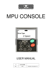
The MPU-PROGRAMMER is a device that allows the setting of characteristic data of the lift on MPU cards
and allows access to diagnostics for alarms that have occurred during operation and are saved on the
control card.
The MPU PROGRAMMER is protected by a customisable access code without which it is impossible to
access any programmer function.
IMPORTANT: This manual is valid for MPU PROGRAMMER with software relese PRG1 R03 or later.
2 – WARNINGS
Read every part of this manual before powering up the device. Follow the power-up procedure step by step
to avoid damaging the programmer or the control card.
Do not use the programmer connected to any appliance other than an MPU board.
Before connecting up the programmer, make sure that the lift is stationary at a floor with the car
empty and that it is not accessible to any user.
3 – CONNECTING THE PROGRAMMER TO THE CARD
1- Before connecting the programmer, disable the pushbutton panels by pushing the lever of switch BEX on
the control card.
2- Now connect the programmer to the control card by inserting the cable with DB9 male connector into the
corresponding DB9 female connector called CN4 on the card (if necessary, plug between the two
connectors the ADAPTER 302.06.ADAT1 - see MPU-2 and/or ECO-MPU User Manual).
3- Program the lift data as described in section 5.
4- When you have finished programming, turn off the power supply, disconnect the programmer and power
up the card again: the lift will make a reset operation and then will be ready for normal operation.
4 – DESCRIPTION OF KEYBOARD AND DISPLAY
The device consists of a display with 5 alphanumeric characters and 5 keys which allow lift parameters to be
modified. The keys are described in Table 1.
Key
Description
Function
ARROW UP
Goes to next function or increases the value of the selected
parameter. It is only the first figure on the right of the display that
increases (units).
ARROW DOWN
Goes to previous function or decreases the value of the selected
parameter. It is only the first figure on the right of the display that
decreases (units).
ARROW LEFT
Multiplies the current figure by 10.
Example: current figure = 3,
press ARROW LEFT,
displayed figure = 30
ARROW RIGHT
Divides the current figure by 10.
Example: current figure = 27,
press ARROW RIGHT,
displayed figure = 2
ENTER
Confirms the parameter or accesses the desired function
Table 1
MPU PROGRAMMER USER MANUAL Release 03 dated 10-02-2003
3
5 – OPERATION OF DEVICE
5.1 – Setting access code
When the programming device is turned on, the display will read Pr1.0.
After pressing ENTER the display will read C 01.
Pressing ENTER again, the display will read 0.
In this condition the device is waiting for the access code that allows the lift parameters to be modified. This
code consists of 5 figures, each of which can have a value consisting of a number from 0 to 9 or one of the
following letters: A, b, C, d, E, F.
Enter the access code using the arrow keys as described in Table 1. Remember that the letters A, b, C, d, E,
F appear after the figure 9.
If the code is not correct, the display will continue to show 0 after you have pressed ENTER to confirm and it
will not be possible to modify the lift parameters.
If the code is correct, the display will read COdE1.
The lift data can now be modified and lift operation is not permitted.
You can now change the access code COdE1 or display or modify the lift parameters.
Press ARROW UP to directly modify the lift parameters (Display reads: F 01).
Instead, press ENTER to display the current access code. Now use the arrow keys to change the access
code as described in Table 1 or press ENTER again to leave it unchanged. After pressing ENTER again, you
can modify the lift parameters (Display reads: F 01).
5.2 – Modifying and displaying the lift parameters
The lift parameters are indicated on the display by the letter “F” followed by two figures from 01 to 72 listed in
Table 2.
To select the various parameters press the ARROW UP key (to increase the function number) or ARROW
DOWN key (to decrease the function number). For example, if the display reads “F05” , to select “F03” you
have to press ARROW DOWN twice and to select “F08” you have to press ARROW UP three times.
To modify the selected parameter, proceed as follows:
♦ When the display reads Fxx, press ENTER to display the current value of the parameter.
♦ The ARROW DOWN and ARROW UP keys decrease or increase the value of the parameter. This
operation affects only the last figure on the right of the display.
♦ The ARROW LEFT and ARROW RIGHT keys multiply or divide the value of the parameter by 10.
♦ When the parameter has the required value, press ENTER to save it.
To view the parameters without changing them, after going to Fxx, simply press ENTER once to view the
value, then press ENTER again to go to the next parameter.
5.3 – Alarm codes
The alarms that have occurred during lift operation are stored under the function “F46”.
To view them, proceed as follows:
♦ Select “F46” on the display.
♦ Press ENTER to view the alarms. They remain in the memory until they are cancelled using the
programmer.
If no alarms are present, the display reads “E----“ .
If one or more alarms are present, the letter “E” appears followed by a number indicating the numerical
code of the alarm. The various alarm codes are listed in Table 3.
Example :
E0207 Car doors not closed or landing doors not locked at floor 7
E06
Reset operation not completed
When the alarm’s numerical code consists of 4 digits, the first two digits after the “E” indicate the type of
alarm and the last two digits the floor at which the alarm has occurred.
♦ Press ENTER when the alarm is displayed to see the number of times the alarm has occurred.
♦ Press ENTER again to go to the next alarm. If there is no subsequent alarm, you will return to the first
alarm.
4
MPU PROGRAMMER USER MANUAL Release 03 dated 10-02-2003
Press ARROW UP to quit function “F46”:
♦ In this situation the display reads CA--- .
♦ Press ENTER to cancel the alarms or press ARROW UP to go to the next function (F47) without
cancelling the alarms.
5.4 – Information on lift operation
There are 4 particular functions that provide information on lift operation.
These are (see Table 2) :
F
F
F
F
59
60
61
62
Number of upward travels
Number of downward travels
Number of door openings
Number of door closings
For example, select F60 and press ENTER to view the number of downward travels performed by the lift: the
display shows the number of travels divided by 100.
♦ On pressing ENTER or ARROW UP the display reads CA---.
♦ Press ENTER to reset the counter; press ARROW UP to go to the next function (F61) without resetting
the counter.
MPU PROGRAMMER USER MANUAL Release 03 dated 10-02-2003
5
Table 2 : PROGRAMMABLE FUNCTIONS
FUNCTION
DESCRIPTION
1 ÷ 27
0 ÷ 27
0=AUTOMATIC PUSH BUTTON; 1=SIMPLEX FULL;
2=DUPLEX or TRIPLEX or QUADRUPLEX;
3=SIMPLEX DOWN
0=1SPEED; 1=2 SPEED; 2=ACVV; 3=VVVF;
4=HYDRAULIC
F 01
F 02
TOP FLOOR
MAIN FLOOR
F 03
LIFT OPERATION
F 04
DRIVE TYPE
F
F
F
F
F
F
F
F
F
F
F
F
F
F
F
F
F
F
F
F
F
F
F
F
F
F
F
F
F
F
F
F
F
DOOR TYPE
DOOR STATUS WHEN CAR WAITS AT FLOOR
NUMBER OF CAR ENTRANCES
FLOOR 0 DOOR OPENING SIDE
FLOOR 1 DOOR OPENING SIDE
FLOOR 2 DOOR OPENING SIDE
FLOOR 3 DOOR OPENING SIDE
FLOOR 4 DOOR OPENING SIDE
FLOOR 5 DOOR OPENING SIDE
FLOOR 6 DOOR OPENING SIDE
FLOOR 7 DOOR OPENING SIDE
FLOOR 8 DOOR OPENING SIDE
FLOOR 9 DOOR OPENING SIDE
FLOOR 10 DOOR OPENING SIDE
FLOOR 11 DOOR OPENING SIDE
FLOOR 12 DOOR OPENING SIDE
FLOOR 13 DOOR OPENING SIDE
FLOOR 14 DOOR OPENING SIDE
FLOOR 15 DOOR OPENING SIDE
FLOOR 16 DOOR OPENING SIDE
FLOOR 17 DOOR OPENING SIDE
FLOOR 18 DOOR OPENING SIDE
FLOOR 19 DOOR OPENING SIDE
FLOOR 20 DOOR OPENING SIDE
FLOOR 21 DOOR OPENING SIDE
FLOOR 22 DOOR OPENING SIDE
FLOOR 23 DOOR OPENING SIDE
FLOOR 24 DOOR OPENING SIDE
FLOOR 25 DOOR OPENING SIDE
FLOOR 26 DOOR OPENING SIDE
FLOOR 27 DOOR OPENING SIDE
INSPECTION SPEED
FORCED DOOR CLOSING DURING RUN
05
06
07
08
09
10
11
12
13
14
15
16
17
18
19
20
21
22
23
24
25
26
27
28
29
30
31
32
33
34
35
36
37
F 38
LANDING CALL CANCELLATION
F
F
F
F
F
F
F
THERMISTOR ALARM RESET
AUTOMATIC RETURN (only for TRACTION LIFT)
AUTOMATIC RETURN FLOOR (only for TRACTION LIFT)
PREFERENTIAL CALL FLOOR
STOP DELAY TIME
CONTACTOR OPENING DELAY TIME
EMERGENCY STOP DELAY TIME
39
40
41
42
43
44
45
F 46
ALARM CODES MEMORY
F
F
F
F
F
F
F
F
F
F
F
F
RETIRING CAM FALL DELAY TIME
DOOR OPENING START DELAY TIME
EMERGENCY MAXIMUM TRAVEL TIME
DOOR OPENING TIME
DOOR CLOSING TIME
HIGH-SPEED TRAVEL TIME
LOW-SPEED TRAVEL TIME
STARTING DELAY TIME
OCCUPIED TIME
AUTOMATIC RETURN ACTIVATION DELAY TIME.
GONG ACTIVATION TIME
CAR FAN AND/OR LIGHT TIME
6
47
48
49
50
51
52
53
54
55
56
57
58
PERMITTED VALUES
0=MANUAL; 1=SEMIAUTOMATIC; 2=AUTOMATIC
0=DOORS CLOSED; 1=DOORS OPEN
1 or 2 ( see NOTE 1)
0 = NONE
1 = SIDE 1
2 = SIDE 2
3 = SIMULTANEOUS
4 = SELECTIVE (see NOTE 2)
0=LOW; 1=HIGH
0=NO; 1=YES
0=SELECTIVE; 1=SIMULTANEOUS
Only used for MUX Software
0=MANUAL; 1=AUTOMATIC
0=NO; 1=YES
0 – 27
0 – 27
0.0 ÷ 2.0 SECONDS ± 0.1
0.0 ÷ 2.0 SECONDS ± 0.1
1 ÷ 15 MINUTES ± 1
1 - 60 SECONDS ± 1
1 - 45 SECONDS ± 1
1 - 60 SECONDS ± 1
1 - 15 MINUTES ± 1
0.1 - 3.0 SECONDS ± 0.1
1 - 255 SECONDS ± 1
MPU PROGRAMMER USER MANUAL Release 03 dated 10-02-2003
Table 2 : PROGRAMMABLE FUNCTIONS (following)
FUNCTION
DESCRIPTION
PERMITTED VALUES
F 59
F 60
60
F
F 61
F 62
F 63
F 64
NUMBER OF UPWARD TRAVELS
NUMBER OF DOWNWARD TRAVELS
NUMBER OF DOOR OPENING MOVEMENTS
NUMBER OF DOOR CLOSING MOVEMENTS
NOT USED
FLOOR SELECTOR SWITCH TYPE
F 65
WHEN THERMISTOR MOTOR PROTECTION TRIPS:…
F 66
PHASE CONTROL ALARM
F 67
NEXT CAR LEAVING DIRECTION SIGNAL
F 68
F 69
NOT USED
RC INPUT OPERATION
0
Not Used
0=ACTIVE HIGH; 1=ACTIVE LOW
F 70
RC INPUTCONTROL FOR HYDRAULIC LIFTS
0=ACTIVE BOTH UPWARD THEN DOWNWARD;
1=ACTIVE ONLY UPWARD
F 71
NUMBER OF LIFTS OF THE GROUP
0=SIMPLEX; 1=DUPLEX; 2=TRIPLEX;
3=QUADRUPLEX
F 72
IDENTIFYING NUMBER OF THE LIFT
0 ÷ 99999
(see NOTE 3)
0
Not Used
0=N.C. CONTACT; 1=N.O. CONTACT
0=THE CAR REACHES THE FLOOR;
1=THE CAR STOPS IMMEDIATELY
0=ENABLED; 1=DISABLED
0=OFF DURIN RUN; 1=ON DURING RUN
Only used for SIMPLEX DOWN or MUX Software
Only used
for MUX
0=SIMPLEX or CAR 1 IN THE GROUP; Software
1=CAR 2; 2= CAR 3; 3=CAR 4
NOTE 1 :
♦ If 1 is selected for F07, viewing the functions goes directly to F36.
♦ If 2 is selected for F07, viewing of the functions proceeds with F08, F09, …etc. up to the function
corresponding to opening side of the top floor (set in F01).
NOTE 2 :
If for a floor SELECTIVE OPENING is selected, it means that for that floor you can make two different calls,
one to open the side 1 doors, and the other to open the side 2 doors.
Selective opening can be selected for only one floor or for more floors, up to 8 as maximum.
The call push-buttons which have to make side 1 to open, have to be connected normally from R0 forward,
such as the push-button calls of floors with none selective opening selected, while the only push-buttons
which have to make the selective opening at side 2 have to be connected from R15 back, connecting to R15
the lowest floor.
EXAMPLE:
Lift system with 6 stops, 2 car entrances, and SELECTIVE OPENING at floors 2 and 4.
The call push-button have to be connected in
this way:
SIDE 1
5
4
3
2
1
0
SIDE 2
0
1
2 – side1
3
4 – side1
5
→
→
→
→
→
→
4 – side2
2 – side2
→ R14
→ R15
R0
R1
R2
R3
R4
R5
NOTE 3 :
The real number of travels or door movements corresponds to the displayed value multiplied by 100.
MPU PROGRAMMER USER MANUAL Release 03 dated 10-02-2003
7
Table 3 : ALARM CODES
ALARM CODE
E
E
E
E
E
E
E
E
E
E
E
E
E
E
E
E
E
E
E
E
01
02….(from 00 to 27)
03….(from 00 to 27)
04
05….(from 00 to 27)
06
07
08
09
10
11
12
13
14
15
16
17
18
20
21
MEANING
INCORRECT PHASE SEQUENCE OR A PHASE LACKING
CAR DOORS NOT CLOSED OR LANDING DOORS NOT LOCKED, at FLOOR from 0 to 27
MOTOR CONTACTORS DO NOT ENERGIZE, at FLOOR from 0 to 27
TDC INPUT NOT CLOSED (from ACVV regulator)
CAR FAILED TO LEAVE, at FLOOR from 0 to 27
RESET OPERATION NOT COMPLETED
DOOR CLOSING TIMER ELAPSED
DOOR OPENING TIMER ELAPSED
HIGH SPEED TRAVEL TIME ELAPSED
LOW SPEED TRAVEL TIME ELAPSED
RE-LEVELLING TRAVEL TIME ELAPSED
CONTACTORS FAIL TO OPEN
FUNZIONAMENTO ANOMALO INTERRUTTORI DI RIFASAMENTO
OVER-TRAVEL
THERMISTOR MOTOR PROTECTION TRIPPED
EXTERNAL ALARM 1
EXTERNAL ALARM 2
NO OPERATING VOLTAGE
PHOTOCELL DARKENED FOR MORE THAN 20 SEC.
NO AUTOMATIC RETURN (HYDRAULIC)
For further information contact::
SMS Sistemi e Microsistemi S.r.l.
Tel. : 051-969037 Fax : 051-969303 Assistenza Tecnica : 051-6720710
Sito : www.sms.bo.it E-mail : [email protected]
Crespellano ( Bologna ) ITALY
8
MPU PROGRAMMER USER MANUAL Release 03 dated 10-02-2003
EVENT
COUNT
( MAX 31 )
YES
YES
YES
YES
YES
YES
YES
YES
NO
NO
NO
YES
YES
NO
YES
YES
YES
YES
YES
YES


