1
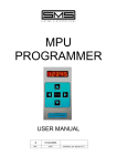
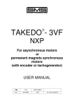
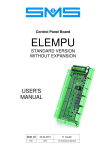
MPU CONSOLE
F04
READY
Drive Type
2 Speed
ready
run
fault
USER MANUAL
1
24-03-2005
REL.
DATE
Verification and Approval R.T.
CONTENTS
1
INTRODUCTION..................................................................................Page
3
2
WARNINGS .........................................................................................Page
3
3
SETTINGS OF THE MPU BOARD ......................................................Page
3
4
CONNECTING THE PROGRAMMER TO THE CARD ........................Page
4
5
DESCRIPTION OF KEYBOARD AND DISPLAY .................................Page
4
6
DEVICE OPERATION..........................................................................Page
5
ECO-MPU: Automatic Push Button (maximum 8 stops)
Table 4 : PROGRAMMABLE FUNCTIONS.......................................Page
7
Table 5 : ALARM CODES .................................................................Page
7
MPU-2: A.P.B,SIMPLEX DOWN,SIMPLEX FULL or MULTIPLEX
2
Table 6 : PROGRAMMABLE FUNCTIONS.......................................Page
8
Table 7 : ALARM CODES .................................................................Page
9
MPU CONSOLE USER MANUAL Release 1 dated 24-03-2005
1 – INTRODUCTION
The MPU-CONSOLE is composed by a keyboard and a display that allows the setting of lift data on MPU
cards and allows access to diagnostics for alarms occurred during operation, which are saved on the control
card.
The MPU-CONSOLE is protected by a personal access code without which it is impossible to enter any
programmer function.
2 – WARNINGS
Read every part of this manual before powering up the device. Follow the start-up procedure step by step to
avoid damaging the programmer or the control card.
Use MPU CONSOLE only connecting it to MPU board.
®
VERY IMPORTANT: Don’t’ use MPU CONSOLE for Takedo 3VF NX (even if the look the
same), otherwise you would not be able to use it on MPU after.
On boards MPU 2 different keyboard can be used:
MPU PROGRAMMER (old type), or MPU CONSOLE (new type).
The 2 keyboards have different supplies and connection, pIs read carefully the following
paragraph to set the MPU board properly.
ANY WRONG SETTING ON THE MPU BOARD WILL CAUSE IRREPARABLE DAMAGE ON
MPU CONSOLE.
Before connecting up the keyboard, make sure that the board is NOT supplied.
3 – SETTINGS OF THE MPU BOARD
ECO-MPU
MPU-2
MPU-CONSOLE : Solder point SP1 in position 1
MPU-CONSOLE : Solder point SP2 in position 1
MPU-PROGRAMMER : Solder point SP1 in
position 2 + fitting cod. 302.06.ADAT1
MPU-PROGRAMMER : Solder point SP2 in
position 2 + fitting cod. 302.06.ADAT1
MPU CONSOLE USER MANUAL Release 1 dated 24-03-2005
3
4 – CONNECTING THE KEYBOARD TO THE CARD
1- Before connecting the programmer, make sure that the lift is stopped at level with empty car, and that
anyone can get in; disconnect supply to the board MPU and to the top of safety chain, opening the
automatic switch.
2- Now connect the keyboard to the board: insert the cable supplied by SMS with DB9 male connector into
the corresponding DB9 female connector on the card. Please check the correct presetting of the board
according to the instruction in section 3.
3- Supply MPU board and proceed programming lift data as described in section 6.
4- Once you have finished programming, turn off power supply, disconnect the programmer and power up
the board and the close the automatic switch again: the lift will make a reset operation and will be then
ready for normal operation.
5 – DESCRIPTION OF KEYBOARD AND DISPLAY
The device consists of a liquid crystal display, 9 keys and 3 LED which allow lift parameters to visualized
and modified. Keys and LED are described in the following Tables 1 and 2.
KEY
ARROW UP
ARROW DOWN
FUNCTION
It skips to next function or increase the value of the selected parameter .
It skips to the previous function or decrease the value of the selected parameter.
ARROW LEFT
It cancels a modification done before entering ENTER , moves the cursor to the left on the
desired digit for a modification .
ARROW RIGHT
It starts a parameter modification, moves the cursor on the desired digit for a modification.
ENTER
It confirms the value of the parameter just modified.
RESET
It resets alarms and contactors.
SELECT
It allows moving from one parameter to another (functions, alarms, contactors, access)
START
Pushing it together with UP ARROW it increases of 10 the digit of the function.
Pushing it together with DOWN ARROW it decreases of 10 the digit of the function.
STOP
NOT USED
Table 1
LED
READY
RUN
FAULT
OPERATION
It is on when the right access code is entered.
NOT USED.
It is on during alarm display, if any.
Table 2
4
MPU CONSOLE USER MANUAL Release 1 dated 24-03-2005
5 – DEVICE OPERATION
The data displayed on MPU CONSOLE are divided in 4 menus, which can be selected with key SELECT
and identified by the first letter at left top of the display. This letter means:
A: Access menu – It allows the modification of the personal access code, and the language of the display.
F: Functions menu – It allows the modification of lift data.
E: Faults menu – It allows the display and reset faults occurred in the lift.
C: Counter menu – It allows the display of information about lift operation.
6.1 – Setting access data
6.1.1 – Access with personal code
When turning on the programming keyboard you will read on the left top of display A01, in the central line
under it you will read “Access Code 1” and in the bottom line it is shown a 8 digit flashing code
“00000000”.
To modify lift data you need to know your personal access code.
This code is made by 8 digits from 0 to 9.
SMS supplies MPU boards with Access Code=00000000.
Enter your personal Access Code by means of the arrow-keys as described in Table 1.
If you enter the wrong code, after confirming it with ENTER, this will keep on flashing on the display until you
enter it right.
If you enter the right code the display will show F01, it will be now possible to modify the lift data. Lift
operation are disabled until man disconnect MPU CONSOLE.
Pressing SELECT key until A01 is shown; it is now possible to modify your personal access code.
6.1.2 – Language choice
MPU CONSOLE allows the language choice: Italian and English are both available, and can be set in A02.
6.2 – Modifying and displaying the lift parameters
The lift parameters are shown on the display by the letter “F” followed by two digits from 01 to nn, which are
listed in Tables 4 and 6 (according to the type of board and application).
To select the different parameters press the ARROW UP key (to increase the index of the parameter) or
ARROW DOWN key (to decrease the index of the parameter). For example, if the display shows “F05” , to
select “F03” you simply press ARROW DOWN twice and to select “F08” simply press ARROW UP three
times.
It is possible to skip 10 values at once, with key START + ARROW UP if you like to increase it, or with
START + ARROW DOWN if you like to decrease it.
To modify the selected parameter, proceed as follows:
♦ When the display shows Fxx, pressing ARROW RIGHT the current value of the parameter will be
flashing.
♦ ARROW DOWN and ARROW UP keys decrease or increase the value of the parameter.
♦ With keys ARROW LEFT and ARROW RIGHT man can place on the following or previous digit of the
parameter, if it is a numeric function.
♦ Once the required value has reached, press ENTER to save it; while pressing ARROW LEFT will exit
without saving the value.
6.3 – Alarm codes
Lift alarms are shown on the display with letter “E”, followed by 2 digits (from 01 to nn).
They can by displayed and reset only.
To view these alarms press SELECT until letter “E” followed by a number on the top angle of the display is
shown.
The first page of the alarms displays “E00” followed by “Total alarms” and by the total number of faults which
have occurred. To view which type of fault has occurred, press key ARROW RIGHT.
If no faults are present, the display reads “Total alarms” followed by “0”.
MPU CONSOLE USER MANUAL Release 1 dated 24-03-2005
5
If one or more alarms are present, the letter “E” followed by a number showing the numerical code of the
alarm, will appear. The different alarm codes are listed in Table 5 and 7, according to type of board and
application.
When the alarm numerical code consists of 4 digits, the first two digits after the “E” specify the type of fault
and the last two digits specify the floor at which the fault has occurred.
Example:
E0207 Car doors not closed or landing doors not locked, at floor 07
E06 Reset operation not completed
♦ The bottom line of the display indicates the nr. times the failure has occurred.
♦ Press ARROW UP to skip to next fault. If no other fault is present, it will go back to the first fault.
♦ To cancel all the faults, press RESET.
6.4 – Information on lift operation
There are 4 counters which supply information regarding lift operation.
To display the counters press SELECT until “C” followed by a digit at the top angle of the display is shown.
The counters which can be displayed are:
C
C
C
C
01
02
03
04
Number of up run
Number of down run
Number of door opening
Number of door closing
Table 3
For example selecting C02, the number of down runs performed by the lift can be displayed.
The number is updated any 100 runs, so the minimum value displayed different from zero is 100.
▪ To reset the counter press RESET.
For further clarification and advice contact:
SMS SISTEMI e MICROSISTEMI s.r.l. (Gruppo SASSI HOLDING)
Cap. Soc. 260.000 i.v.
Via Guido Rossa, 46/48/50 40056 Crespellano BO
R.E.A 272354 CF - Reg. Imprese Bo 03190050371 P.IVA IT 00601981202
Tel. : +39 051 969037 Fax : +39 051 969303 Technical Service: +39 051 6720710
Web : www.sms.bo.it E-mail : [email protected]
6
MPU CONSOLE USER MANUAL Release 1 dated 24-03-2005
Table 4 : PROGRAMMABLE FUNCTIONS FOR ECO-MPU: Automatic Push Button Lift (max 8 STOPS)
FUNCTION
DESCRIPTION
POSSIBLE VALUES
F 01
TOP FLOOR
1÷7
F 04
DRIVE TYPE
0=1SPEED; 1=2SPEED; 2=ACVV; 3=VVVF; 4=HYDRAULIC
F 05
DOOR TYPE
0=MANUAL; 1=SEMIAUTOMATIC; 2=AUTOMATIC
F 06
DOOR CONDITION AT FLOOR
0= DOORS CLOSED; 1= DOORS OPENED
F 09
INSPECTION SPEED
0=HIGH; 1=LOW
F 10
DOOR IN FORCED CLOSING
0=NO; 1=YES
F 12
THERMISTOR ALARM RESET
0= MANUAL; 1= AUTOMATIC
F 13
AUTOMATIC RETURN (only for TRACTION LIFT)
0=NO; 1=YES
F 14
AUTOMATIC FLOOR RETURN (only for TRACTION LIFT)
0÷7
F 16
STOP DELAY TIME
0.0 ÷ 2.0 SECONDS ± 0.1
F 17
CONTACTOR OPENING DELAY TIME
0.0 ÷ 2.0 SECONDS ± 0.1
F 18
EMERGENCY STOP DELAY TIME
0.0 ÷ 2.0 SECONDS ± 0.1
F 19
RETIRING CAM FALL DELAY TIME
0.0 ÷ 2.0 SECONDS ± 0.1
F 20
DOOR OPENING START DELAY TIME
0.0 ÷ 2.0 SECONDS ± 0.1
F 21
EMERGENCY MAXIMUM TRAVEL TIME
1 ÷ 15 MINUTS ± 1
F 22
DOOR OPENING TIME
1 ÷ 60 SECONDS ± 1
F 23
DOOR CLOSING TIME
1 ÷ 60 SECONDS ± 1
F 24
TRAVEL TIME IN HIGH SPEED
1 ÷ 45 SECONDS ± 1
F 25
TRAVEL TIME IN LOW SPEED
1 ÷ 45 SECONDS ± 1
F 26
STARTING DELAY TIME
1 ÷ 60 SECONDS ± 1
F 27
CAR OCCUPIED TIME
1 ÷ 60 SECONDS ± 1
F 28
AUTOMATIC RETURN ACTIVATION DELAY TIME
1 ÷ 15 MINUTS ± 1
F 29
GONG ACTIVE TIME
0.1 ÷ 3.0 SECONDS ± 0.1
F 30
CAR FAN OR LIGHT TIME
F 32
TYPE OF SWITCHES FOR SELECTOR CONTROL
1 ÷ 255 SECONDS ± 1
0=NC CONTACT; 1=NO CONTACT
F 33
THERMISTOR ALARM ACTIVATION
0=AT RUN END; 1=IMMEDIATE STOPPING
F 34
PHASE CONTROL ALARM
0=UNABLE ; 1=DISABLE
F 36
EMERGENCY FLOOR
F 37
CONTACTOR CONTROL INPUT OPERATING (RC)
F 38
CONTACTOR CONTROL FOR HYDRAULIC LIFTS
0÷7
0=ACTIVE HIGH; 1=ACTIVE LOW
0=ACTIVE CONTROL EITHER UP OR DOWN;
1=ACTIVE CONTROL ONLY DOWN
Table 5: Alarms code for ECO-MPU : Automatic Push Button Lifts (8 STOPS max)
ALARM CODE
E 01
MEANING
COUNTING OF
( MAX 31 )
YES
E 03.(from 00 to 07)
INCORRECT PHASE SEQUENCE OR A PHASE LACKING
CAR DOORS NOT CLOSED OR LANDING DOORS NOT LOCKED,
at FLOOR from 0 to 07
MOTOR CONTACTORS DO NOT ENERGIZE, at FLOOR from 0 to 07
E 04
TDC INPUT NOT CLOSED (from ACVV regulator)
YES
E 05.(from 00 to 07)
CAR FAILED TO LEAVE, at FLOOR from 0 to 07
YES
E 06
RESET OPERATION NOT COMPLETED
YES
E 07
DOOR CLOSING TIMER ELAPSED
YES
E 08
DOOR OPENING TIMER ELAPSED
YES
E 09
HIGH SPEED TRAVEL TIME ELAPSED
NO
E 10
LOW SPEED TRAVEL TIME ELAPSED
NO
E 11
RE-LEVELLING TRAVEL TIME ELAPSED
NO
E 12
YES
E 14
CONTACTORS OPENING FAILURE
LIMIT SWITCH (ULS, DLS) OR SELECTOR SWITCH (USS, DSS)
OPERATION NOT CORRECT
OVER-TRAVEL
E 15
THERMISTOR MOTOR PROTECTION TRIPPED
YES
E 16
EXTERNAL ALARM 1
YES
E 17
EXTERNAL ALARM 2
YES
E 18
NO OPERATING VOLTAGE
YES
E 20
PHOTOCELL DARKENED FOR MORE THAN 20 SEC.
YES
E 21
NO AUTOMATIC RETURN (HYDRAULIC)
YES
E 02.(from 00 to 07)
E 13
MPU CONSOLE USER MANUAL Release 1 dated 24-03-2005
YES
YES
YES
NO
7
Table 6 : PROGRAMMABLE FUNCTIONS FOR MPU-2
Note :
Fmax = 15 for A.P.B. software and automatic push button operation
Fmax = 08 for A.P.B. software and simplex down operation
Fmax = 27 for MUX software (simplex full or multiplex)
FUNCTION
DESCRIPTION
POSSIBLE VALUES
F 01
TOP FLOOR
1 ÷ Fmax
F 02
MAIN FLOOR
F 03
LIFT OPERATION
F 04
DRIVE TYPE
0 ÷ Fmax
0=A.P.B.; 1=SIMPLEX FULL;
2=MULTIPLEX; 3=SIMPLEX DOWN
0=1SPEED; 1=2SPEED; 2=ACVV; 3=VVVF; 4=HYDRAULIC
F 05
DOOR TYPE
0=MANUAL; 1=SEMIAUTOMATIC; 2=AUTOMATIC
F 06
DOOR CONDITION AT FLOOR
0= DOORS CLOSED; 1= DOORS OPENED
F 07
F 08
(from 00 to Fmax)
F 09
NUMBER OF CAR ENTRANCES
1 or 2
0= NONE; 1= SIDE 1; 2=SIDE 2;
3= SIMULTANEOUS; 4=SELECTIVE (see NOTE 1).
0=LOW; 1=HIGH
F 10
FORCED DOOR CLOSING DURING RUN
F 11
LANDING CALL CANCELLATION
F 12
THERMISTOR ALARM RESET
F 13
AUTOMATIC RETURN (only for TRACTION LIFT)
0=NO; 1=YES
F 14
AUTOMATIC FLOOR RETURN (only for TRACTION LIFT)
0 ÷ Fmax
F 15
VIP CALL FLOOR
0 ÷ Fmax
F 16
STOP DELAY TIME
0.0 ÷ 2.0 SECONDS ± 0.1
F 17
CONTACTOR OPENING DELAY TIME
0.0 ÷ 2.0 SECONDS ± 0.1
F 18
EMERGENCY STOP DELAY TIME
0.0 ÷ 2.0 SECONDS ± 0.1
F 19
RETIRING CAM FALL DELAY TIME
0.0 ÷ 2.0 SECONDS ± 0.1
F 20
DOOR OPENING START DELAY TIME
0.0 ÷ 2.0 SECONDS ± 0.1
F 21
EMERGENCY MAXIMUM TRAVEL TIME
1 ÷ 15 MINUTES ± 1
F 22
DOOR OPENING TIME
1 ÷ 60 SECONDS ± 1
F 23
DOOR CLOSING TIME
1 ÷ 60 SECONDS ± 1
F 24
TRAVEL TIME IN HIGH SPEED
1 ÷ 45 SECONDS ± 1
F 25
TRAVEL TIME IN LOW SPEED
1 ÷ 45 SECONDS ± 1
F 26
STARTING DELAY TIME
1 ÷ 60 SECONDS ± 1
F 27
CAR OCCUPIED TIME
1 ÷ 60 SECONDS ± 1
F 28
AUTOMATIC RETURN ACTIVATION DELAY TIME
1 ÷ 15 MINUTES ± 1
F 29
GONG ACTIVATION TIME
0.1 ÷ 3.0 SECONDS ± 0.1
F 30
CAR FAN OR LIGHT TIME
F 31
SELECTOR TYPE
1 ÷ 255 SECONDS ± 1
0
NOT USED
F 32
TYPE OF SWITCHES FOR SELECTOR CONTROL
0=NC CONTACT; 1=NO CONTACT
F 33
THERMISTOR ALARM ACTIVATION
0=AT RUN END; 1=IMMEDIATE STOPPING
F 34
PHASE CONTROL ALARM
F 35
NEXT CAR LEAVING DIRECTION SIGNAL
F 36
EMERGENCY FLOOR
F 37
CONTACTOR CONTROL INPUT OPERATING (RC)
F 38
CONTACTOR CONTROL FOR HYDRAULIC LIFTS
F 39
NUMBER OF LIFTS OF THE GROUP
F 40
LIFT IDENTIFYING NUMBER
F 41
ZONE TIMEOUT
F 42
EARLY DOOR OPENING
0=UNABLE ; 1=DISABLE
0=OFF DURING RUN; 1= ON DURING RUN
Used only for SIMPLEX DOWN or MUX Software
0 ÷ Fmax
0=ACTIVE HIGH; 1=ACTIVE LOW
0=ACTIVE CONTROL EITHER UP OR DOWN;
1=ACTIVE CONTROL ONLY DOWN
0=SIMPLEX; 1=DUPLEX;
2=TRIPLEX; 3= QUADRUPLEX
0=SIMPLEX or CAR 1; 1=CAR 2;
Used only for
2=CAR 3; 3=CAR 4
MUX Software
1 ÷ 5 MINUTES ± 1
0=DISABLED; 1=ENABLED
8
DOOR OPENING SIDE from 00 to Fmax
INSPECTION SPEED
0=NO; 1=YES
0=SELECTIVE; 1=SIMULTANEOUS
Used only for MUX Software
0=MANUAL; 1=AUTOMATIC
MPU CONSOLE USER MANUAL Release 1 dated 24-03-2005
Table 7: Alarms code for MPU-2
Note :
Fmax = 15 for A.P.B. software and automatic push button operation
Fmax = 08 for A.P.B. software and simplex down operation
Fmax = 27 for MUX software (simplex full or multiplex)
ALARM CODE
E 01
MEANING
COUNTING OF
( MAX 31 )
E 03.(from 00 to Fmax)
INCORRECT PHASE SEQUENCE OR A PHASE LACKING
CAR DOORS NOT CLOSED OR LANDING DOORS NOT LOCKED,
at FLOOR from 0 to Fmax
MOTOR CONTACTORS DO NOT ENERGIZE, at FLOOR from 0 to Fmax
YES
E 04
TDC INPUT NOT CLOSED (from ACVV regulator)
YES
E 05.(from 00 to Fmax)
CAR FAILED TO LEAVE, at FLOOR from 0 to Fmax
YES
E 06
RESET OPERATION NOT COMPLETED
YES
E 07
DOOR CLOSING TIMER ELAPSED
YES
E 08
DOOR OPENING TIMER ELAPSED
YES
E 09
HIGH SPEED TRAVEL TIME ELAPSED
NO
E 10
LOW SPEED TRAVEL TIME ELAPSED
NO
E 11
RE-LEVELLING TRAVEL TIME ELAPSED
NO
E 12
YES
E 14
CONTACTORS OPENING FAILURE
LIMIT SWITCH (ULS, DLS) OR SELECTOR SWITCH (USS, DSS)
OPERATION NOT CORRECT
OVER-TRAVEL
E 15
THERMISTOR MOTOR PROTECTION TRIPPED
YES
E 16
EXTERNAL ALARM 1
YES
E 17
EXTERNAL ALARM 2
YES
E 18
NO OPERATING VOLTAGE
YES
E 20
PHOTOCELL DARKENED FOR MORE THAN 20 SEC.
YES
E 21
NO AUTOMATIC RETURN (HYDRAULIC)
YES
E 02.(from 00 to Fmax)
E 13
YES
YES
YES
NO
NOTE 1 :
The floor SELECTIVE OPENING is possible only for Automatic Push Button operation.
If a floor SELECTIVE OPENING is programmed, it means that for that floor two different calls are possible,
one to open the side 1 doors, and the other to open the side 2 doors.
Selective opening can be programmed for only one floor or for more floors, up to 8 as maximum.
The call push-buttons corresponding to side 1 opening have to be connected normally from R0 forward, such
as the push-button calls of floors with none selective opening selected. The only push-buttons corresponding
to side 2 opening have to be connected from R15 back, connecting to R15 the lowest floor.
EXAMPLE:
Lift system with 6 stops, 2 car entrances, and SELECTIVE OPENING at floors 2 and 4.
The call push-button have to be connected in
this way:
SIDE 1
5
4
3
2
1
0
SIDE 2
0
1
2 – side1
3
4 – side1
5
→
→
→
→
→
→
R0
R1
R2
R3
R4
R5
4 – side2
2 – side2
→ R14
→ R15
MPU CONSOLE USER MANUAL Release 1 dated 24-03-2005
9