1
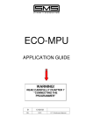
V-MOD
MODERNISATION KIT WITH VVVF
FOR 1 OR 2 SPEED SYSTEMS
INSTRUCTION MANUAL
0
20-10-2013
REV.
DATE
Verification and Approval R.T.
PAGE INTENTIONALLY LEFT BLANK
2
V-MOD
INSTRUCTION MANUAL Version 0 of 20-10-2013
1 – INTRODUCTION
SMS thanks you for your choice.
V-MOD is a device that allows the easy conversion of old 1 or 2 speed lift systems in lift systems with VVVF
frequency converter, without replacing the gear, the motor, the control panel and the shaft and car electrical
system.
V-MOD complies with the 2004/108/EC and 95/16/EC directives.
V-MOD contains a latest generation frequency converter, the Vacon V20, which is particularly sturdy, being
equipped with oversized power components and equipped with specific software for lifts, that makes it easily
adaptable to any type of motor, even of old construction.
It is coupled to the interface card with the existing control panel that, with a few simple settings, can be
readily applied to any type of control panel: with relay, with PLC, with microprocessor card, etc.
In the case of 1 speed system, the card also includes the "Travel Time" control: this protection enables
replacement of the gear without having to install the device for limiting the motor supply time, as prescribed
in paragraph 12.10 of UNI 10.411_1.
V-MOD is available in 3 sizes:
V-MOD CODE
INPUT VOLTAGE
3-PHASE 50-60HZ
(Vac)
RATED
CURRENT
(A)
MAXIMUM
CURRENT
(A)
VMD0012.4S0
380...480
12
24
VMD0016.4S0
380...480
16
32
VMD0017.2S0
208…240
17.5
35
V-MOD
INSTRUCTION MANUAL Version 0 of 20-10-2013
3
2 – INSTALLATION
V-MOD is completely pre-wired, i.e. it comes equipped with the following cables, already connected to the
corresponding terminals:
• a cable for power connection of the device to the mains.
• a shielded cable to connect the output of the inverter to the control panel.
• the shielded cables required for connection of the interface card to the control panel.
8 meters of shielded cable are also provided for power connection between the control panel and the motor.
2.1 GETTING STARTED
1- For the installation of V-MOD in an existing system with 1 speed motor, the hoistway must be
transformed as if it were a 2 speed installation, bearing in mind that the existing stop control becomes a
deceleration control and that the factory settings values of the inverter are right for a deceleration
distance as indicated in the following table:
DECELERATION DISTANCE TABLE
System nominal speed (m/s)
Necessary deceleration distance (mm)
0.7
1.0
1.2
1000
1400
1700
The greater the deceleration distance, the more comfortable the system.
Also requiring installation are the stop switch on the car (for the connection 2 additional conductors are
required in the flexible cable) as well as magnets along the shaft, at each level.
The magnets must be the same length, must be centered with respect to the floor level, in exactly the
same position for all the levels, see the "STOP DISTANCE TABLE" below:
STOP
MAGNET
STOP DISTANCE TABLE
=
.
=
D
HEIGHT
OF
LEVEL
System nominal speed (m/s)
0.7
1.0
1.2
Total stop distance (D) (mm)
60
80
100
2- For installation of V-MOD in a system operating at 2 speeds, to ensure more comfortable arrival simply
bring forward the existing deceleration control
(see " DECELERATION DISTANCE TABLE " above).
Stop switches, mounting brackets and magnets can be provided with the product upon specific request, or
where SMS deems it is necessary, as a result of examination of the diagram of the existing control panel
provided by the Customer.
IMPORTANT :
SMS offers customers a service FREE OF CHARGE for the diagram analysis and
related changes for the V-MOD application. If upon order the control panel diagram
is provided, the diagram is returned together with V-MOD, upgraded with the
necessary modifications.
SMS encourages customers to take advantage of this service because in the
absence of provision of the modified diagram, it is not able to guarantee the postsales helpline service.
3 – CONNECTIONS
ATTENTION!
Before making the connections, bring the car to an intermediate floor and disconnect all the
power sources.
IMPORTANT :
V-MOD is ready for connection to control panels where the operation voltage is
between 48V and 110V, ac or dc.
Application is possible in control panels with different operation voltage, in particular
230Vac, but the proper establishment must be requested to SMS at the time of the
order.
4
V-MOD
INSTRUCTION MANUAL Version 0 of 20-10-2013
3.1 POWER CIRCUIT
The V-MOD power connection should be made upstream of the motor contactors: Always ensure that the
operation transformer is derived upstream of V-MOD.
- INTERRUPT the connection between the three-phase power supply and the contactor power contacts.
- CONNECT the INPUT cable (3 Poles + Earth, unshielded, terminals L1, L2, L3) to the three-phase power
supply of the control panel.
- CONNECT the OUTPUT cable (3 Poles + Earth, shielded, terminals U, V, W) to the contactor power
contacts.
In this way the frequency converter is in series between the mains power and the contactor power
contacts and is always powered.
- Connect the earth conductors and the shield of the shielded cables to the earth of the control panel and of
the gear.
IMPORTANT
The connection between the contactors and the motor (i.e., between the control panel and motor),
must be replaced with the shielded cable (3 Poles + Earth) supplied with V-MOD.
The shield must be connected to the earth on both sides.
INPUT
CABLE
L1 L2 L3
V-MOD
3—PHASE MAINS
3 POLES+EARTH
U V W
OUTPUT
CABLE
OPERATION
TRANSFORMER
CONTROL
PANEL
MOTOR
CONTACTORS
CABLE
CONTROL PANEL - MOTOR
M
3 ~
Fig. 1 : Power connection
ATTENTION!
When connecting V-MOD there are problems with the differential switch type AC, 30mA.
When installing a frequency converter, in order to avoid undesired interventions of the differential switch and
to ensure effective protection (in compliance with the Rules) perform the following:
- Ensure that the building has an effective earthing system.
-
Install a differential switch with Id not less than 300mA, type B or type A
(more effective is type B) .
V-MOD
INSTRUCTION MANUAL Version 0 of 20-10-2013
5
3.2 INTERFACE CARD
The card inside the V-MOD box provides for interfacing of the inverter with the existing control panel and to
manage the brake on the gear fast shaft.
On the card there are some configuration Dip-Switches that have the following meaning:
SW
OFF:
ON:
1 = EXISTING DRIVE
1 Speed
2 Speed
2 = IM INPUT FUNCTION
NC (open in INSPECTION) NO (closed in INSPECTION)
3 = CF INPUT FUNCTION
NC (open at FLOOR level)
NO (closed at FLOOR level)
4 = MOTOR CONTROL
OPEN LOOP
CLOSED LOOP
(only valid with NXP inverter)
The position of the Switch must always be set or modified with V-MOD off.
Connections to the interface card, valid for both 1 and 2 speed:
TFL2, TFL3
TF-
Brake control relay voltage-free contact
Interrupt the connection of the power to the brake coil and connect in series the contact
between TFL2 - TFL3. In this way, the brake is still safely controlled by the motor contactors
but the logic of opening and closing is managed by the inverter.
Connect to the negative of the brake coil
VMOD Card
BRAKE POWER
SUPPLY
TFL2
RF
RF
TFL3
EXISTING CONTACTOR
CONTACTS
BRAKE
TF-
QP+, QP-
Start permit
Connect respectively to the positive and negative poles of the operation circuit, downstream
of the safety chain contacts.
IM, QM
Inspection control
Connect to the control panel so that the voltage between IM and QM signals the operation in
inspection.
If the voltage is only present in inspection, set SW 2 = ON, if the voltage is only present in
normal operation and is absent in inspection, set SW 2 = OFF.
This signal is used to perform inspection operation at medium speed and to ensure that the
inverter shuts off immediately at stop, without enabling electric stop.
Connections to the interface card, for 1 speed systems:
SET SW 1 = OFF
CF, CF1
Stop command.
Connect the new stop switch, with N.C. contact (open at floor level) or N.O. (closed at floor
level);
- if the contact is N.C. set SW 3 = OFF
- if the contact is N.O. set SW 3 = ON
QU, QUA
Upward command.
Interrupt the connection of the upward branch of the floor switches or selector circuit.
Connect the wire from the above upward branch to the QU wire, and the terminal where the
wire was previously connected, to the QUA wire.
6
V-MOD
INSTRUCTION MANUAL Version 0 of 20-10-2013
QD, QDA
Downward command.
Interrupt the connection of the downward branch of the floor switches or selector circuit.
Connect the wire from the above downward branch to the QD wire and the terminal where
the wire was previously connected, to the QDA wire.
QC2
Common of the operation circuit (usually, but not always, the earth of the control panel).
Connect to the reference of the operation voltage that supplies the QU /QD inputs, bearing in
mind that V-MOD controls the starting sequence when the presence of voltage between QU
and QC2 or between QD and QC2 is detected.
QC1.
Supply voltage of motor contactors or auxiliary relays.
Connect in the point of the safety chain from which is derived the power supply for the coils
of the contactors or auxiliary relays, bearing in mind that V-MOD continues to power these
coils to the end of the electric stop controlled by the inverter.
Figure 2 below shows an example of application on a control panel in which there are auxiliary relays and
contactors, where the connections QC1 – QC2 – QU / QUA, QD / QDA – QP+ – QP- are indicated
QC2
QU
QC1
AS
UPWARD
CONTROL
FLOOR RELAY
CONTACTS AND
FLOOR SWITCHES
OR SELECTOR
CIRCUIT
DOOR CONTACTS
QUA
QD
QDA
UPWARD
AUXILIARY RELAY
AD
DOWNWARD
AUXILIARY RELAY
DOWNWARD
CONTROL
UPWARD
CONTACTOR
QP+
CONTACTOR
CONTROL
MAIN
CONTACTOR
QPDOWNWARD
CONTACTOR
Fig. 2 : Example of connection on a generic 1 speed relay control panel.
It is important to remember that this is only one of the possible types of diagram, there are many
existing variants and as such, SMS is able to accurately indicate the correct connections of V-MOD
only on the specific diagram, provided by the customer at the time of order
(see IMPORTANT indication at the bottom of Page 3).
Connections to the interface card, for 2 speed systems:
SET SW 1 = ON
CF
CF1
Do not connect
Deceleration and stop control.
Connect to the Low Speed contactor coil and set SW 3 = OFF.
QU, QUA
Upward command.
Interrupt connection to the upward contactor coil.
Then connect the wire previously connected to it to the QU wire and the upward contactor
coil to the QUA wire.
QD, QDA
Downward command.
Interrupt the connection to the downward contactor coil.
Then connect the wire previously connected to it to the QD wire and the downward contactor
coil to the QDA wire.
V-MOD
INSTRUCTION MANUAL Version 0 of 20-10-2013
7
QC2
Common of the operation circuit (usually, but not always, the earth of the control panel).
Connect to the reference of the operation voltage that supplies the CF1 / QU / QD inputs,
bearing in mind that V-MOD controls the starting sequence when the presence of voltage
between QU and QC2 or between QD and QC2 is detected.
QC1
Supply voltage of contactors.
Connect at the end of the safeties chain,fwhere the supply voltager for the contactor coils is
derived, bearing in mind that V-MOD continues to power the upward/downward contactors
until the end of the electric stop controlled by the inverter.
IN ADDITION:
•
In case of 2-speed motor, the inverter controls only the HIGH Speed winding and as such the LOW
speed winding connections must be removed.
•
For the above reason, ensure that the HIGH speed contactor remains powered for the whole run, thus
becoming a RUN contactor.
•
Also ensure that the control panel does not command the opening of any automatic doors upon arrival in
the stop area but only after fall of the contactors.
The early opening of the doors will result in Alarm 68 on the inverter, and after 20 interventions the
system freezes.
Figure 3 below shows an example of application on a control panel, in which the contactors are represented
and where the QU / QUA, QD / QDA – CF1 – QC1 – QC2 – QP+ – QP- are indicated.
QC1
DOOR CONTACTS
UPWARD/DOWNWARD
CONTROL CONTACTORS
QU
QD
QUA
QDA
S
D
HIGH/LOW SPEED
CONTROL
CONTACTORD
CF1
QC2
QPS
UPWARD
D
HIGH
SPEED
LOW
SPEED
DOWNWARD
Fig. 3 : Example of connection on a generic electronic 2 speed control panel.
It is important to remember that this is only one of the possible types of diagram, there are many
existing variants and as such, SMS is able to accurately indicate the correct connections of V-MOD
only on the specific diagram, provided by the customer at the time of order
(see IMPORTANT indication at the bottom of page 3).
8
V-MOD
INSTRUCTION MANUAL Version 0 of 20-10-2013
4 - V-MOD CARD MAP AND SIGNAL LED MEANING
LED
A
MEANING
=
=
=
B
IM
QD
QU
QUA
QDA
QP
RUN
CC
RF
CF
=
=
=
=
=
=
=
=
=
=
=
Flashing
→Indicates that the card is correctly operating:
Off for a long time then 2 →Indicates that after the deceleration, the car failed to achieve
flashes:
the level within 10 sec.
Off for a long time then 4 →Indicates that the max. travel time in high speed has expired
flashes:
Failure to start
Inspection service
Downward command
Upward command
Upward contactor control
Downward contactor control
Safety Chain contacts closed
Rub command for the inverter
Inverter running
Brake control
Stop command
V-MOD
INSTRUCTION MANUAL Version 0 of 20-10-2013
9
5 – OPERATION
Operation sequence for modernisation of 1-speed systems
When the VMOD card receives an upward or downward command from the control panel (QU or QD),
V-MOD controls the activation of the contactors and, via the inverter, the car movement in HIGH speed.
On the card the following Leds will go ON in sequence QU/QD, QUA/QDA, QP, RUN, DC, RF, CF (if the
stop switch is N.C. otherwise from ON, it switches OFF).
When the control panel switches off the command (QU or QD), the corresponding Led (QU/QD) switches off
and the deceleration to LOW speed is performed.
When the car reaches the floor level, CF switches, the inverter electrically stops the motor and in succession,
the fall of the brake and then of the contactors: the leds RF, CC, RUN, QUA/QDA, QP switch OFF in
sequence.
V-MOD is provided with a maximum travel time protection:
If the time required for the run between one level and the next one exceeds 45 sec (counting starts again at
any floor level), the system stops and it will not start again.
This status is displayed in the V-MOD card with the green led A that, cyclically, stays off and then flashes
four times quickly. To resume operation it is necessary to remove and restore the power supply voltage.
A further function of the V-MOD card is the control of the low speed time:
If the car slows down but does not reach the floor level (switching of CF) within 10 sec, the system stops.
This event is displayed in the V-MOD card with green Led A that, cyclically, stays off and then flashes twice
quickly. This situation continues until there is a new starting command.
Operation sequence for modernisation of 2-speed systems
When the VMOD card receives an upward or downward command from the control panel (QU or QD),
V-MOD controls the activation of the contactors and, if CF is not active, via the inverter commands the car
movement in HIGH speed.
On the card the following Leds will go ON in sequence QU/QD, QUA/QDA, QP, RUN, CC and RF.
When the CF command is active (with the QU/QD command remaining active), the CF LED goes ON and
the deceleration to LOW speed is performed.
When the car reaches the floor level, CF and/or QU/QD will switch off, the inverter electrically stops the
motors and in succession, the fall of the brake and then of the contactors: the leds RF, CC, RUN, QUA/QDA
and QP switch OFF in sequence.
For 2 speed systems, the control of the maximum travel time is not provided either in HIGH or LOW
speed to avoid inappropriate interventions of these protection in the case of long travel (due to the type of
CF operation, it is not in fact possible to restart the count at any floor level) or long distances covered at low
speed, for example during start-up.
(These checks are normally already provided for in the electronic control panels).
Other functions of the VMOD card
FAILURE TO START SIGNALLING
The signalling of failure to start (coming on of Led B), occurs when the inverter, after having received the
RUN command , does not activate the CC signal (inverter running). This is typically caused by an "Alarm" of
the inverter, the code for which is shown on the display of the keyboard of the inverter itself.
After 2 seconds it is possible to command a new start: if this time the CC signal is activated, the Led B
switches off and the car normally starts, otherwise the Led B remains on to indicate the failure to start.
INSPECTION SERVICE
The inspection service is indicated by Led IM, ON in inspection if Dip-Switch 2 = ON, or OFF in inspection
and ON in normal service if Dip-Switch 2 = OFF.
The movement is controlled via the inspection control box and occurs in MEDIUM speed, the value of which
can be changed by means of the parameter P2.8.
When the inspection run button is released, the command QU or QD switches OFF, and the car stops with
immediate shutdown of the inverter.
BUTTONS ↑ / ↓
On the card there are 2 buttons, ↑ and ↓, to directly control the movement of the car
This movement can only be controlled if the safety chain is closed (Led QP ON) and only if the system is in
NORMAL operation, NOT in INSPECTION service.
The type of operation, however, is the same as the inspection one, i.e. running in MEDIUM speed and stop
with immediate shutdown of the inverter when the button is released.
10
V-MOD
INSTRUCTION MANUAL Version 0 of 20-10-2013
6 - FINE TUNING
After making the CONNECTIONS, open the V-MOD box and close the F.M. general switch, holding the
operation valve open.
On the card, the green led A must flash.
Firstly, enter the motor data in the group "BASIC PARAMETERS" - P1.2 ÷ P1.6 into the inverter. The
prompts to change the parameters are found within the manual TAKEDO 3VF V20 attached.
Close the operation valve.
Make a call for an upper floor, ensuring that the gear rotates in the correct direction. If it does not rotate in
the correct direction, reverse two phases of the motor power supply (for example U with V).
Having verified the correct direction of rotation, return the car to an intermediate floor.
Perform a new call: check the correct sequence of operation on the board with reference to the previous
paragraphs.
Having successfully concluded the operations described above it is possible to optimise operation of the
system. It is possible to adjust acceleration, deceleration and final deceleration.
To reduce the installation time, perform adjustments to a single floor level, performing travel upward and
downward until a satisfactory stop is obtained. The magnets of the other floors must be equal and positioned
in the same way, centered with respect to the floor level.
7 - DIMENSIONS AND WEIGHT
SIZES 12 / 16A
Length
(mm)
Height
(mm)
Depth
(mm)
Weight
(kg)
323
322
158
11
For further information and advices please contact:
SMS SISTEMI e MICROSISTEMI s.r.l. (Gruppo SASSI HOLDING)
Cap. Soc. 260.000 i.v.
Via Guido Rossa, 46/48/50 40056 Crespellano BO
R.E.A 272354 CF - Reg. Imprese Bo 03190050371 P.IVA IT 00601981202
Tel. : +39 051 969037 Fax : +39 051 969303 Technical Service: +39 051 6720710
Web : www.sms.bo.it E-mail : [email protected]
V-MOD
INSTRUCTION MANUAL Version 0 of 20-10-2013
11