1
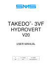
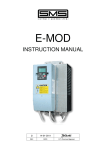
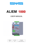
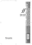
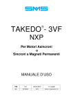
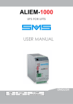
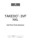
®
TAKEDO -3VF
V20
INSTRUCTION MANUAL
6
06-10-2015
D. Cavalli
REL.
DATE
T.M. Check and Approval
www.sms-lift.com
PAGE INTENTIONALLY LEFT BLANK
1 – INTRODUCTION
TAKEDO-3VF V20 is a new type of drive with built-in EMC filter, responding to the European Directives
2004/108/EC (EMC) and 2006/95/EC (Low Voltage Equipment).
The inverter can operate only in open loop condition.
This manual provides you with the essential information about the connections in the control panel and the
inverter operation (use of the keypad, parameter and fault message list).
Complete Information for the application can be found in the original INSTALLATION MANUAL from VACON
(inverter series Vacon 20 Cold Plate) available on the site www.vacon.com.
2 – SAFETY WARNINGS AND CAUTIONS
For everything related to the warnings about personal safety and prevention of accidental damage to any
product or equipment connected to it, refer to Chapter “SAFETY” of the original INSTALLATION MANUAL
from VACON (inverter series Vacon 20 Cold Plate) available on the site www.vacon.com, where you
can also find the “Declaration of Conformity”, reported, however at the end of this document.
Read this manual carefully and in its entirety before powering up the equipment.
With regard to the specific application on lifts, please consider carefully the following points:
1- The leakage current from the inverter to earth is greater than 30mA, and accordingly, the power
circuit must incorporate a residual current device with Id no less than 300mA, type B or type A.
Regulations require that the connection to earth are made with cable of not less than 10 mm² section. If
the residual current device should trip closing the main power switch, do not perform this
operation repeatedly because this could lead to permanent damage to the inverter drive. Check
that the residual current device is rated at least 300mA.
2- Connection to mains: once per minute or less
3- To avoid damaging the inverter in case of prolonged stoppages with no power supply, before
restarting the drive proceed as follows:
- If the inverter has been idle for several months, connect it to the power supply for at least 1
hour in such a way as to recharge the bus capacitors.
- If the inverter has been idle for more than one year, supply it for 1 hour with a level of voltage
50% lower than the nominal input voltage, and then supply it with the nominal input voltage for
1 hour.
4- It is advisable to balance the system at 50%. If balanced at 40%, the UP current under full load will be
greater, and it could be necessary to select a drive with a higher specification than the normally needed
ones.
TAKEDO - 3VF V20 USER MANUAL Release 6 date 06-10-2015
3
3 – TECHNICAL DATA
INVERTER V20 series 400 VOLT (380 – 480V)
RATED
CURRENT
In (A)
OVERLOAD
CURRENT
Ia (A)
MAXIMUM
CURRENT
Is (A)
CODE
DIMENSIONs
WxHxD
(mm)
FUSES
gG/gL
(A)
12
18
24
TKV00124
175x275x138
20
16
24
32
TKV00164
175x275x138
25
INVERTER V20 series 230 VOLT (208 – 240V)
RATED
CURRENT
In (A)
OVERLOAD
CURRENT
Ia (A)
MAXIMUM
CURRENT
Is (A)
CODE
DIMENSIONs
WxHxD
(mm)
FUSES
gG/gL
(A)
17,5
26
35
TKV00172
175x275x138
25
In = Rated Continuous Current
Ia = Overload Current (150%) for 1 minute every 10’
Is = Maximun Current (200%) for 2 seconds every 20’’
Enclosure Operating Temperature = -10°C…+70°C
Stand-by Consumption
= 10W
IMPORTANT!
The corrent values are referred to the maximum temperature (70°C), and to 6kHz
switching frequency.
The inverter power components are “oversized”, in the sense that each model is
equipped with IGBT whose rated current is the one of the higher size.
Example: Code TKV00124, rated current = 12A, is provided with 16A IGBT.
BRAKING RESISTOR
CODE
SUPPLIED BY SMS
(Ω) - (W)
RECOMMENDED
MINIMUM VALUE
(Ω)
DIMENSIONS
WxHxD (mm)
TKV00124
65Ω – 500W
(004.16.W0065)
50
200x35x30
TKV00164
N°2 33Ω - 500 W in serie
(004.16.W0033 x 2)
50
260x36x27
TKV00172
33Ω - 500 W
(004.16.W0033)
25
260x36x27
4 – CONNECTING THE POWER CIRCUIT
L1; L2; L3
A.C. Power Input
U/T1;V/T2;
Inverter output
W/T3
DC+;BR
External Braking Resistor
Earth
Connect the three phases of the power supply to this three
terminals, in any order.
Connect the three output phases to the contactors, then to the
motor
Connect the external braking resistor
Connect to the building earth system
With regard to the cable dimensioning and the terminal position, please refer to the Chapter “POWER
CABLING” of the original INSTALLATION MANUAL from VACON (inverter series Vacon 20 Cold Plate)
available on the site www.vacon.com.
4
TAKEDO - 3VF V20 USER MANUAL Release 6 date 06-10-2015
5 – CONTROL CIRCUITS
Number
1
2
3
4
5
6
7
8
9
10
11
Meaning
Control Terminals A-20
STO Terminals
Relay Terminals
Option Board Terminals
STO Jumpers
DIP Switches:
SW1 in position 0, the common of the digital inputs (8-10 e 14-16)
is connected to the ground (default position);
in position 1, the common above is isolated from ground.
SW2 AI1 analogue input operating mode;
SW3 AI1 analogue input operating mode;
in position 0, the selected analogue input works in current mode;
in position 1, the analog input works in voltage mode (default position);
the voltage range is 0…10V and the current range is 0/4…20mA.
SW4 used for bus termination, related to the RS485 connection;
in position 0, the termination resistance is connected;
in position 1 is not connected (default position).
Status Led:
“PWR” Orange the drive is supplied by mains
“RUN” Green the drive is running
“FLT” Red
the drive is in fault
“RDY” Orange the drive is ready and no fault is present
it starts blinking when a warning is active
HMI connector (RJ45 keypad connector)
Braking Resistor Terminals
Supply Voltage connector for fan
Control Terminals A-20 Remote Connector
TAKEDO - 3VF V20 USER MANUAL Release 6 date 06-10-2015
5
6
TP
TP1
EMERGENCY
DOWN
UP
INSPECTION SPEED
LOW SPEED
6
TAKEDO - 3VF V20 USER MANUAL Release 6 date 06-10-2015
RO2
RO1
26
25
22
23
(GND)7
13
20
6
7
18
DC-
BR
DC+
W/T3
V/T2
U/T1
SHIELDED CABLE
SHIELDED CABLE
SHIELDED CABLE
TAKEDO
ENERGY
BRAKING
RESISTOR
EARTH CABLE
TP1
CONTACTORS
TP
N.B.: THE FILTER IS ACCOMMODATED INSIDE THE INVERTER.
TO ENSURE ADEQUATE ELECTROMAGNETIC COMPATIBILITY,
THE INPUT AND OUTPUT CABLES MUST BE SHIELDED..
DO1
(-)
(+)
TAKEDO 3VF
V20
+24Vdc
I<100mA
10 (DI3)
9 (DI2)
8 (DI1)
16 (DI6)
15 (DI5)
14 (DI4)
L3
T
HIGH SPEED
L2
L1
S
SHIELDED CABLE
THREEPHASE
LINE
R
SHIELDED CABLE
SHIELDED
CABLE
M
3-PH
– OPERATION
TB BRAKE CONTACTOR
Imax<400mA ; Vmax<=125 Vdc
+ OPERATION
FAULT RELAY
Imax<400mA ; Vmax<=125 Vdc
CONTACTOR CONTROL
and/or SAFETY BRAKE
OPEN COLLECTOR OUTPUT
I<50mA D.C. ; V=24 Vdc
(OPTION)
SHIELDED
CABLE
6 – APPLICATION DRAWING
6.1 – WITHOUT ENABLE LOGIC
TAKEDO - 3VF V20 USER MANUAL Release 6 date 06-10-2015
BRAKE SWITCHES
TP1
The monitoring of micro-contacts of the
brake on slow shaft does not require the
Declaration of Conformity according to
the Amendment 3 of the EN 81-1 Standards.
TP
EMERGENCY
DOWN
UP
INSPECTION SPEED
LOW SPEED
R
R=
1K2Ω
1/4W
R
RO2
RO1
26
25
23
22
(GND)7
13
20
6
7
18
DC-
BR
DC+
W/T3
V/T2
U/T1
SHIELDED CABLE
SHIELDED CABLE
TAKEDO
ENERGY
BRAKING
RESISTOR
EARTH CABLE
TP1
CONTACTORS
TP
N.B THE FILTER IS ACCOMMODATED INSIDE THE INVERTER.
TO ENSURE ADEQUATE ELECTROMAGNETIC COMPATIBILITY,
THE INPUT AND OUTPUT CABLES MUST BE SHIELDED.
4 (DI8) P3.8=2
2 (DI7) P5.6=7
6
DO1
(-)
(+)
TAKEDO 3VF
V20
+24Vdc
I<100mA
10 (DI3)
9 (DI2)
8 (DI1)
16 (DI6)
15 (DI5)
14 (DI4)
L3
T
HIGH SPEED
L2
L1
S
SHIELDED CABLE
THREEPHASE
LINE
R
SHIELDED CABLE
SHIELDED
CABLE
M
3-PH
– OPERATION
TB BRAKE CONTACTORS
Imax<400mA ; Vmax<=125 Vdc
+ OPERATION
FAULT RELAY
Imax<400mA ; Vmax<=125 Vdc
CONTACTORS CONTROL
And/or SAFETY BRAKE
OPEN COLLECTOR OUTPUT
I<50mA D.C. ; V=24 Vdc
(OPTION)
SHIELDED
CABLE
6.2 – WITH ENABLE LOGIC AND BRAKE SWITCH CONTROL
7
7 – NXOPTB5 EXPANDER BOARD (OPTION)
The NXOPTB5 board allows you to add N° 3 RELAY OUTPUTS.
Terminals
Function
DEFAULT Setting (*)
22 - 23
RO1 N.O. Contact
P6.10 = 4 CONTACTORS
25 - 26
RO2 N.O. Contact
P6.11 = 4 CONTACTORS
28 - 29
RO3 N.O. Contact
P6.12 = 5 FREQUENCY SUPERV.
Contact Technical Information
Switching capacity:
Min. switching load:
(*) See Page 13 for other possible settings.
8
TAKEDO - 3VF V20 USER MANUAL Release 6 date 06-10-2015
24VDC/8A
250VAC/8A
125VDC/0,4A
5V/10mA
8 – EMERGENCY (EVACUATION) OPERATION
TAKEDO-3VF V20 can work supplied by batteries, or by an UPS (uninterruptible power supply), to move the
car and bring it to the floor in case of mains power supply failure.
The minimum voltage of the batteries is 96V, furthermore is necessary an auxiliary voltage 230Vac 50/60Hz
to enable the inverter control logic (current about 300mA).
Alternatively, the UPS must have 230Vac 50/60Hz output, adequate power.
The emergency operation is activated by enabling the input 10 and the parameters for the management of
emergency operation are in GROUP 9.
P9.1 EMERGENCY MODE:
0 = NOT USED
Emergency Disabled
1 = MANUAL
It does not select the favourable run direction;
The motor follows the run direction the inverter is commanded for.
2 = AUTOMATIC It selects the favourable run direction;
The inverter allows for the quick rotation of the motor in both run directions and then
chooses the most favorable run direction.
P9.2 EMERGENCY MAXIMUM FREQUENCY:
It is the maximum speed of the motor, whatever the speed level activated (high, low, inspection, etc.).
7.1 – COMMAND SEQUENCE FOR EMERGENCY OPERATION WITH 96V BATTERIES
Be sure that mains power and emergency power (batteries or UPS) can’t be never simultaneous, and
the exchange between one to the other power is delayed at least by a 2 seconds interval.
Plese follow carefully the indications below, looking to the figure:
AUXILIARY
SUPPLY
230Vac 50/60Hz
3 – PHASE
LINE
230VAC
Ke
Ke
Ke2
BATTERIES
96V
RT
L1
L2
L3
10
VACON
V20
U
V
U
V
M
3~
Ke
6
W
CONTACTORS
W
10
6
1) After a few seconds from mains supply
failure, it is necessary to cut off the mains
power of the inverter and of the control
panel.
On the left figure, the energization of Ke
contactor cuts off the inverter power and
closes the contact between terminals 6/10,
to indicate to the inverter that the emergency
operation is required.
2) After about 2 seconds from Ke energization,
power again the control panel and activate
the RT relay, that has to stay active for 3
seconds, so that during this time the
terminals L2 – L3 are supplied by 230Vac
voltage.
Once RT relay is de-energized, Ke2
contactor will energize, powering L1 – L2
terminals with battery voltage.
3) The control panel can now start its operation
like in normal condition.
By means of a car call or a reset operation,
the control panel will provide the run and
speed level commands to the inverter: the
car will be brought to the desired floor or to
the first encountered floor, depending on the
setting of the parameter P9.1.
4) At the end of the emergency operations,
inverter has to be un-powered from batteries
(contactor Ke2 de-energized).
5) After 2 seconds more, inverter power and
control panel power have to be reconnected
to the mains (through Ke de-energizion) to
allow the normal operation restore.
In case of mains power restart during emergency, it is recommended to bring to the end the emergency
cycle.
.
TAKEDO - 3VF V20 USER MANUAL Release 6 date 06-10-2015
9
9 – KEYPAD AND PROGRAMMING
The control keypad is the interface between
TAKEDO-3VF V20 and the user, and must be connected to
the connector shown in the figure, via the cable supplied.
With the keypad it’s possible to check the status of the motor and the inverter, and to set the drive
parameters.
The BUTTON section is shown in the following picture:
NOT USED
NOT USED
NOT USED
The DISPLAY section indicates the status of the motor and the drive, and any irregularities in motor or drive
functions.
On the display, the user can see the information about his present location in the menu structure and the
item displayed.
10
TAKEDO - 3VF V20 USER MANUAL Release 6 date 06-10-2015
9.1 – MENU STRUCTURE
The data on the control keypad are arranged in menus:
• Use the UP and DOWN arrows to move between the menus.
• Enter the group/item by pressing the OK button and return to the former level by pressing the
BACK/RESET button.
The arrow on the left of the display shows the active menu.
The TABLE below shows the structure of the main menu:
Reference from keypad
Reference (REF)
Monitoring values
Monitor (MON)
Application Parameters
Parameters (PAR)
Active Fault
Fault (FLT)
(divided into ACTIVE FAULT and HISTORY FAULT)
9.2 – USING THE KEYPAD
9.2.1 EDITING VALUES
To change the value of a parameter, follow the procedure below:
1. Locate the parameter
2. Enter the Edit mode by pressing OK
3. Set new value with the Arrow buttons UP/DOWN.
You can also move from digit to digit with the Arrow buttons LEFT/RIGHT.
4. Confirm change with ok button
(or ignore change by returning to previous level with BACK/RESET button).
9.2.2 RESETTING FAULT
When a FAULT appears and the drive stops, examine the cause of the fault using the TABLE at
Chapter 10 – ACTIVE FAULTS, then reset the Fault by pressing the BACK/RESET button for a while.
10 – MONITOR MENU
This menu allows to see some data during the inverter operation and it is divided into 2 sub-menu.
Contents
Description
Contents Description
Output Frequency
Frequency Reference
Motor Speed
Motor Current
Motor Torque
V1.6
V1.7
V1.8
V1.9
Motor Power
Motor Voltage
Motor Temperature
Actual Output Frequency
RO1
Fault
RO2
Brake
DO1
Contactors
(term.22-23)
(term.25-26)
(term.6-20)
1 – Motor
V1.1
V1.2
V1.3
V1.4
V1.5
2 – Inverter
V2.1
DC Link Voltage
V2.7
V2.2
V2.8
Analog Output
V2.3
Unit Temperature
Board Temperature
V2.9
V2.4
DI1
Up
DI2
Down
DI3
Emergency
(term.8)
(term.9)
(term.10)
Anticipated contactor openings at stop
Board NXOPTB5 programmable outputs:
RO1
RO2
RO3
Contactors Contactors
Frequency Superv.
DI4
High
DI5
Low
DI6
Inspection
(term.14)
(term.15)
(term.16)
DI7
DI8
STO
(term.2)
(term.4)
(term.STO)
V2.5
V2.6
V2.10
TAKEDO - 3VF V20 USER MANUAL Release 6 date 06-10-2015
11
11 – PARAMETER MENU
(Default Values for 400V series)
Par.
Description
1 – BASIC PARAMETERS
Unit
Default
P1.1
P1.2
P1.3
P1.4
P1.5
P1.6
P1.7
A
V
Hz
rpm
A
1,8 x Inv
400
50
1380
0,8 x Inv
0,76
0
Hz
s
s
s
Hz
Hz
Hz
Hz
Hz
Hz
Hz
s
Hz
s
50
2,5
2,0
0,5
50
5
30
25
25
25
25
1,20
0,00
0,00
0
A
s
s
Hz
%
s
s
0,7 Iinv
0,00
0,40
1,50
10,0
0,00
0,30
0
0
Current limit
Motor nominal voltage
Motor nominal frequency
Motor nominal speed
Motor nominal current
Motor Cos Phi
Identification
2 – CONFIGURATION
P2.1
P2.2
P2.3
P2.4
P2.5
P2.6
P2.7
P2.8
P2.9
P2.10
P2.11
P2.12
P2.13
P2.14
P2.15
Maximum frequency
Acceleration time
Deceleration time
Final deceleration time
V1 High speed
V2 Low speed
V3 High + Low speed
V4 Inspection speed
V5 High + Inspection speed
V6 Low + Inspection speed
V7 High + Low + Inspection speed
Ramp shape
Smooth start frequency
Smooth start time
Manual doors
3 – BRAKE CONTROL
P3.1
P3.2
P3.3
P3.4
P3.5
P3.6
P3.7
P3.8
P3.9
DC braking current
DC braking time at start
DC braking time at stop
DC braking frequency
Brake open current
Brake open delay
Brake close delay
Brake 1 logic
Brake 2 logic
4 – DRIVE CONTROL
P4.1
P4.2
P4.3
P4.4
P4.5
P4.6
P4.7
P4.8
P4.9
P4.10
P4.11
P4.12
P4.13
P4.14
P4.15
P4.16
P4.17
P4.18
Brake chopper
Brake chopper threshold
Motor control mode
Switching frequency
Torque boost
U/f ratio selection
Field weakening point
Voltage at field weakening point
U/f curve mid point frequency
U/f curve mid point voltage
Output voltage at zero frequency
Identification current
Motor stator voltage drop
Low switching frequency
Change switching frequency threshold
Low noise modulator
Motor smooth start
Smooth start time
1
650
1
8,0
1
2
50
100
1,75
6,00
3,50
50
0,00
5,0
5,00
1
1
9
V
kHz
Hz
%
Hz
%
%
%
%
kHz
Hz
5 – INPUT SIGNALS
P5.1
P5.2
P5.3
P5.4
P5.5
P5.6
P5.7
P5.8
12
Start upward
Start downward
Preset speed B0
Preset speed B1
Preset speed B2
Run Enable
Brake 1 signal
Brake 2 signal
TAKEDO - 3VF V20 USER MANUAL Release 6 date 06-10-2015
1
2
4
5
6
0
8
(DI1)
(DI2)
(DI4)
(DI5)
(DI6)
(DI7)
(DI8)
0
Value
Par.
Description
… following INPUT SIGNALS
P5.9
P5.10
Unit
Evacuation
Identification by No Speed
Default
Value
3 (DI3)
0
6 – OUTPUT SIGNALS (for CONFIGURATION see BELOW)
P6.1
P6.2
P6.3
P6.4
P6.5
P6.6
P6.7
P6.8
P6.9
P6.10
P6.11
P6.12
P6.13
P6.14
P6.15
P6.16
P6.17
P6.18
Relay output 1 content
Relay output 2 content
Digital output content (Open Collector)
Digital An/Out content
Relay output 1 ON delay
Relay output 1 OFF delay
Relay output 1 Inversion
Relay output 2 ON delay
Relay output 2 OFF delay
B5 Board: RO1 relay output content
B5 Board: RO2 relay output content
B5 Board: RO3 relay output content
Analog output function
Analog output minimum
Analog output scale
Analog output filter time
Frequency supervision
Frequency supervision value
s
s
s
s
%
s
Hz
1
3
4
3
0,00
0,00
0
0
0
4
4
5
0
0
100,0
0,00
1
30,00
7 – PROTECTIONS
P7.1
P7.2
P7.3
P7.4
P7.5
P7.6
P7.7
P7.8
P7.9
P7.10
P7.11
P7.12
P7.13
P7.14
Earth fault protection
Motor stall protection
Motor stall delay
Motor stall minimum frequency
Thermal protection of the motor
Motor ambient temperature
Motor cooling factor at zero speed
Motor thermal time constant
Response to thermistor fault
STO Alarm
Parameter Lock
Maximum advanced contactor opening number
Input phase protection
Input phase fault max. ripple
s
Hz
C
%
M
2
0
5,0
15,00
0
40
40,0
45
2
1
0
20
0
18
8 – AUTORESET
P8.1
P8.2
P8.3
P8.4
Automatic reset
Trial time
Wait time
Automatic restart tries
s
s
1
60,0
3,0
3
9 – EVACUATION
P9.1
P9.2
P9.3
P9.4
Evacuation mode
Maximum evacuation frequency
Current read delay
Switching frequency
Hz
s
kHz
2
5,00
3,0
3,0
DIGITAL OUTPUT CONFIGURATION
The digital outputs (relays, Open Collector) and the analogue output used as digital (P6.1 ÷ P6.4) can
assume the following functions::
0=
Unused output
1=
Inverted fault
2=
Fault
3=
Brake control
4=
Motor contactors control
5=
Frequency supervision
NOTE:
When an output is programmed as frequency supervision (e.g. motor speed control), the
parameters defining the output switching values are as follows:
P6.17 =
0
No supervision
=
1
Output ON at low frequency (lower than P6.18) (DEFAULT)
=
2
Output ON at high frequency (higher than P6.18)
P6.18 = Frequency switching value (Default = 30Hz)
TAKEDO - 3VF V20 USER MANUAL Release 6 date 06-10-2015
13
12 – FAULT MENU
In this MENU you find the ACTIVE FAULTS and the FAULT HISTORY.
12.1 ACTIVE FAULTS
When a Fault appears, the display with the name of the fault starts to blink.
The most common fault messages are listed below. Be careful not to reset the alarm or fault without first
having investigated the problems that caused the protection function to trip.
Always put OFF the run command before resetting any fault.
To reset operation, press the BACK/RESET button for a while.
1 Overcurrent: The inverter has detected excessively high current.
2 Overvoltage: DC voltage of the intermediate circuit is above the specified limits.
Earth fault: The current measurement system has detected that the sum of motor phase current values
3 is not equal to 0.
System fault:
8 Component fault. Defective operation. Braking resistor not connected.
9 Undervoltage: DC voltage of the intermediate circuit is below the specified limits.
13 Inverter undertemperature: Temperature of the heat sink is lower than –10°C.
14 Inverter overtemperature: Temperature of the heat sink is above 90°C.
15 Motor stall: The motor stall protection has tripped.
Motor overtemperature: The motor temperature module of the inverter has detected overheating of the
16 motor. The motor is overloaded.
17 Motor underload: The motor underload protection has tripped.
19 Power overload: reduce the load.
25 Watchdog fault: Microprocessor fault.
STO disabled:
30 The alarm display can be disabled by means of P7.10, if STO is used as Enable (P5.6= 9)
35 Application error
IGBT Temperature: The IGBT overtemperature protection device has detected excessively high short-
41 term overload current.
50 Current at the analog input is < 4mA.
51 External fault: Fault signal at the digital input.
53 Field bus fault: The data connection between field bus Master and field bus board is interrupted
54 Field bus interface fault
55 Thermistor
59 Run error: no speed command received after 5 seconds from direction command.
60 Levelling response: Anticipated stop referred to low speed. Car reaches floor while still decelerating.
61 Low current. Brake timeout. Motor current too low and brake fails to open.
Low reference: With a speed level active and below the DC electrical braking start frequency (P3.4),
64 the inverter stops and, after three trips, this error code is generated.
Anticipated opening of the contactors: (See Alarm 68 NOTE)
68 Contactors between inverter and motor opened before the end of the electrical DC braking current.
No Enable: It can occur only If you use the ENABLE input (P5.6=4), indicates that the Enable input
69 has not been activated within 2 seconds from contactor command.
72 Brake Open NOK: one safety brake input control has not detected the brake opening after a command
73 Brake Close NOK: one safety brake input control has not detected the brake opening after a command
Time out enable:
78 the ENABLE input is active, without direction and speed commands
80 System Software not correct
Low voltage configuration not correct - Active in evacuation
81 The inverter hasn’t got the correct configuration to operate with low voltage.
Alarm 68 NOTE
14
After 20 trips of this alarm, the drive goes out of service and you have to press the
BACK/RESET button for a while to resume the operation.
Eliminate the malfunctioning by delaying the contactors opening. If you can’t do this (for
example, in lifts with manual doors, where people opens the car door while car is
stopping, set parameter P2.15 to 1.
If the alarm still occurs, please contact SMS.
TAKEDO - 3VF V20 USER MANUAL Release 6 date 06-10-2015
12.2 FAULT HISTORY
10 latest Faults are stored in the FAULT HISTORY.
Select the FLT Menu, moving the menu indicator on the left, a letter S will appear.
Press OK and then eventually the LEFT ARROW until the display shows F6.1: this is the first fault stored in
the memory, ie the last occurred in the time, press OK to see the CODE.
Press BACK/RESET to go back to F6.1 and then LEFT ARROW followed by DOWN ARROW to go to the
next fault F6.2, and so on to scroll down all the faults stored in the memory.
13 – ADJUSTMENTS
SPEED
CURVE
P2.3
P2.12
P2.13
P2.12
P2.12
P2.12
P3.4
P2.4
P2.2
P2.5
P2.6
P3.1
RUN
COMMAND (8 or 9)
HIGH SPEED
COMMAND (14)
LOW SPEED
COMMAND (9)
P2.14
SMOOTH START
DC BRAKING
CURRENT
When the
parameter
P3.5
is fulfilled
the brake will
open
DC BRAKING TIME AT
START P3.2
DC BRAKING TIME AT
STOP
P3.3
0,3sec
MOTOR
CONTACTORS
BRAKE COMMAND
DELAY
BRAKE OPENING DELAY AT
START P3.6
BRAKE CLOSING DEALAY
AT STOP P3.7
BRAKE CONTROL
RELAY
(mors. 25-26)
MECHANICAL
BRAKE
BRAKE LIFTNG
MECHANICAL DELAY
BRAKE DROPPING
MECHANICAL DELAY
Before attempting any adjustment or modification of the parameters, proceed as follows:
13.1 – SET THE MOTOR DATA IN PARAMETERS P1.2/3/4/5/6
- If the motor speed is not known, or if the nominal value on data plate is 1500 rpm:
if the motor is 1 or 2 speed, or for conventional ACVV regulator, set 1350/1380 rpm
if it is for a VVVF speed regulator, set 1440 rpm.
- If the cos phii value is not known:
if the motor is 1 or 2 speed, or for conventional ACVV regulator, set 0,76
if it is for a VVVF speed regulator, set 0,80.
13.2 – PLACE THE DECELERATION COMMANDS AT A DISTANCE FROM FLOOR AS
INDICATED IN THE TABLE
(GREATER THE DISTANCE, MORE SMOOTHLY THE LIFT SYSTEM WILL OPERATE)
DECELERATION DISTANCES TABLE
Lift system nominal speed (m/s)
Required deceleration distance (mm)
0.7
1.0
1.2
1000
1400
1700
In addition, position the stop switch centrally with respect to the floor.
TAKEDO - 3VF V20 USER MANUAL Release 6 date 06-10-2015
15
The STOPPING DISTANCES TABLE shows guideline values to consider in order to define activation
distance of the stop switch (or switches):
STOP
MAGNET
STOPPING DISTANCES TABLE
=
=
D
FLOOR
LEVEL
Lift system nominal speed (m/s)
0.7
1.0
1.2
Total stopping distance (D) (mm)
60
80
100
The stopping adjustment is performed using the inverter parameters as indicated below (Heading 13.7–5).
13.3 – SET THE EXACT VALUES FOR MAXIMUM FREQUENCY P2.1 (CORRESPONDING
TO THE NOMINAL SPEED OF THE LIFT SYSTEM) AND NOMINAL SPEED (HIGH
SPEED) P2.5.
13.4 – ADJUST THE INSPECTION FREQUENCY P2.8 IN SUCH A WAY THAT CAR SPEED
DOES NOT EXCEED 0.63 m/s.
13.5 – ALWAYS ENSURE THAT THE FREQUENCY VALUES SET IN PARAMETERS P2.1 AND
P2.5 ÷ P2.11 ARE COMPATIBLE WITH THE NOMINAL MOTOR FREQUENCY.
For example, gearboxes may be equipped with motors whose rated frequency can be 30Hz, 38Hz,
45Hz, 55Hz, 60Hz, etc.
13.6 – AUTOTUNING (or IDENTIFICATION)
After setting the correct motor data, it is essential to perform the IDENTIFICATION routine.
- Set parameter P1.7 to 1 and transmit a call command within 10 seconds.
- When contactors energize and the inverter receives the
commands, on the keypad the RUN arrow lights on, but
the motor stays stopped. After a few seconds the RUN
arrow switches off and the STOP arrow lights on
(Identification END).
- Delete the call command (for example opening the
operation switch in the controller). At the contactor
opening the parameter P1.7 turns automatically to 0.
- The boost parameters are now updated.
Verify that the Identification has been successful
checking that the values of the parameters below are
different from the default ones:
Par.
Description
P4.9
P4.10
P4.11
U/f curve mid point frequency
U/f curve mid point voltage
Output voltage at zero frequency
Unit
Hz
%
%
Default Value
1,75
5,00
3,50
If you modify any motor data, it is essential to perform the IDENTIFICATION routine again.
13.7 – FINAL ADJUSTMENTS
After having performed the operations described in points 13.1/2/3/4/5/6, test the lift system and if necessary
perform the following checks and adjustments:
IMPORTANT
Always change no more than ONE PARAMETER AT A TIME
1 - Adjust
starting by means of the following parameters:
JERK
P3.6
P2.13
P2.14
CONTRA-ROTATE
Brake open delay
Smooth start frequency
Smooth start time
The departure must be “smooth”, without sudden movements or opposite rotations.
If an higher torque at starting is needed, increase the value in P4.10 by 1 or 2 units, checking that
the motor current in low speed is a bit higher than the one in high speed, but it doesn’t exceed the
nominal current of the drive.
If the lift system doesn’t work as expected, contact the SMS Technical Support.
2 - Ensure that motor rpm is as requested and speed is constant at high speed.
If the speed is not constant (fluctuating) adjust parameter P1.4. (motor speed), reducing or increasing
the rpm number.
16
TAKEDO - 3VF V20 USER MANUAL Release 6 date 06-10-2015
3 - Now check the deceleration phase: the lift must reach the floor after covering a short distance at
constant speed (max. 10 cm) without any fluctuation or vibration, and maintaining the same speed both
in up and down travel, with the car full or empty.
Adjust the distance travelled at low speed by means of parameter P2.3 (Deceleration time).
4 - If the motor stops when the deceleration
reach the floor, adjust the following parameters:
P1.4
Motor speed
P4.10
V/F mid point voltage
P2.6
Low speed level
phase terminates, and the car is unable to
5 - On arrival at the floor the alignment between floor and car is not perfect:
The parameters to adjust are:
Stops
Stops
BEFORE
AFTER
P2.4
Final deceleration time
P2.6
Low speed level
P3.4
DC Current Frequency
If the stopping level is different in LOAD or NO-LOAD condition, increase the value in P4.10 as
indicated in 13–7.1
IMPORTANT
For the low speed frequency, we recommend a value of approximately 1/10 of nominal
frequency: e.g. 5Hz in the case of a nominal 50Hz motor.
14 – DIMENSIONS AND MOUNTING HOLES
TAKEDO - 3VF V20 USER MANUAL Release 6 date 06-10-2015
17
For further information and advice contact:
SMS SISTEMI e MICROSISTEMI s.r.l. (SASSI HOLDING Group)
Via Guido Rossa, 46/48/50 Loc. Crespellano 40053 Valsamoggia BO - ITALIA
Tel. : +39 051 969037 Fax : +39 051 969303 Technical Service: +39 051 6720710
E-mail : [email protected] Internet : www.sms-lift.com
18
TAKEDO - 3VF V20 USER MANUAL Release 6 date 06-10-2015
TAKEDO - 3VF V20 USER MANUAL Release 6 date 06-10-2015
19