1
OWNER'S MANUAL
FOR
Visual Display Dispenser
JT30
MODEL
JT30
JT30-W25
JT30-W26
USA
Export
Export
Refrigerant Rl34a
Manufactured by IMI Cornelius/Jet Spray Corporation
2401 N. Palmer Drive, Schaumburg, IL 60196
Phone
U.S. & Canada
Oul<;ide U.S.
1-888-248-5568
1-630-539-5050
Fax
U.S. & Canada
Outside U.S.
1-800-344-3801
1-630-539-6960
September 1995
Printed in the U.S.A.
Your Standard of Excellence for Beverage Mercflandisi11g
011
Document No. 18480
Revision No. 03
Six Continents
General Description
The JTJO dispenser is a countertop visual display action beverage dispenser.
It is designed to dispenser a variety of products.
Warning:
1. This appliance must be earthed.
2. This appliance is not suitable for use by unsupervised children.
Location
Power Cord
Place the dispenser on a solid, level surface with no
part of the unit extending beyond the edge ofthat
surface.
If the power cord becomes damaged, do !!.Q!
attempt to repair it. Take the unit to your nearest
authorized dealer as a special tool is required.
Power and Water
~
The JS7 requires a 120 Volt, 60Hz grounded
receptacle for the unit's power cord.
UK
USA
INTERN ATJONAL
JS P/N
A5291
S1249
Al632
The JS7-W25 requires a 230V, 50 Hz earthed
receptacle for the units po~er cord.
Operating Adjustments
The JS7-W26 requires a 208V/230V, 60Hz earthed
receptacle for the units power cord plug.
W.arning: Dangerous voltages are still present
within the unit even if the power switch is turned
off. Before attempting any adjustments inside the
unit, turn the unit off and unplug it from the
electrical receptacle.
If the colors of the wires in the main leads of
this appliance do not correspond with the colored
markings identifying the terminals in your plug,
proceed as follows.
Note:
-The green and yellow wire must be connected to the
terminal in the plug marked with any of the
following:
tcolored green
.the letter E
tcolored both green and yellow
tthe earth symbol
-The blue wire must be connected to the terminal in
the plug marked with the letter Nor colored blue.
-The brown wire must be connected to the terminal in
the plug marked with the letter L or colored orange.
Notes:
Attention is drawn to the requirements ofNational Regulations about connecting to and using Potable water supplies.
Jet Spray dispensers conform to the requirements of the Model Water Bylaws of 1986 SI 1147.
All surfaces which come into contact with food or drinking water are constructed offood quality non-toxic materials.
are non-corrosive, non-tainting and do not support the grovtth of bacteria.
Jet Spray Corporation reserves the right to make changes
in design and!or engineering without notice.
Your Standard of Excellence for Beverage Merchandising on Six Continents
1
Specifications
JT30 Series
A.
Electrical
PIN
Electrical Supply
RLA
Running Power
LRA
JT30
A8530
120VAC, 60Hz
8.3 AMPS
996 Watts
35 AMPS
JT30-W25
A8540
230V AC, 50 Hz
3.0 AMPS
690 Watts
12 AMPS
JT30-W26
A8560
220V AC, 60 Hz
4.6 A.\1PS
1012Watts
12 AMPS
Model
RLA- Runnmg Load Amperage
LR.A - Locked Rotor Amperage (compressor starting amperage)
B.
Class of Windings
Compressor Motor- Class H (climatic rating; normal)
Condenser Fan Motor-. Class B
C.
Environment
Temperature
Operating: 60°F (!~C) to ll0°F (43°C)
Storage: Above- 20°F (-7"C) with bowl empty and dry.
Humidity- Below 95%
D.
Refrigeration (Rl34a refrigerant)
Model
Charge Quantity
JT30
JT30-W25
JT30-W26
186grams(6.6oz)
186 grams (6.6 oz)
186 grams (6.6 oz)
Your Standard of Excellence for Belierage Merchandising on Six Continents
2
Installation and Operating Instructions
Setting up your Dispenser
1.
2.
Set dispenser chassis in desired location.
Dispenser should be level and located on a solid
counter.
Be sure dispenser has adequate free space on
both sides; approximately 3" away from any
wall or obstruction.
Handle Support
Sealing Button
Clips
Cleaning the Dispenser
1.
2.
Spout
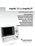
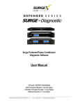
Removing the Push Handle
a. Push handle back until it stops.
b. Grasp clips on handle. Squeeze clips until
they are free from panel. Pull straight down
on handle (see Fig. 1).
Disassemble the bowl, lid, gasket, and pump
housing assemblies.
Handle
Tube Path
Fig. 1
Note: To remove pump housing, push back on top
of housing just below spray tube and lift out of bowl.
Clean in wann water and mild nonabrasive detergent
and rinse thoroughly.
CAUTION: Abrasive cleaners will scratch plastic
parts.
To Assemble
1.
2.
Slide the drip tray with grille into place.
Consider installation of a drain hose which
connects to outlet on drip tray bottom (Part No.
S-3379).
3.
4.
5.
Tum bowl upside down and insert gasket into
groove. Wet gasket for ease of insertion,
pressing gasket into groove while following
numbers in sketch opposite.
Install bowl spout gasket (See Fig 2).
Lock pump housing in the bowl by pushing
housing straight into bowl location until it snaps
into position. Press down on top ofthe impella
section to assure it is down all the way into well
section (see Fig. 3).
Fig. 2
Note: !fa bowl circulator kit is used in place ofthe
pump housing assembly, see page 5A for assembly.
Fig. 3
Your Standard of Excellence for Beverage Merchandising on Six Continents
3
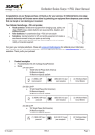
6.
Lock spray tube in by pushing down in
opening, then rotate clockwise.
Correctly installed tube will face front of bowl
(See Fig. 4).
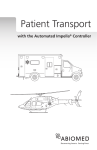
b.
c.
d.
Remove pinch tube from plastic bag and
wash.
Before installing, wet bowl spout surface
and pinch tube. Push back handle until it
stops.
Carefully insert pinch tube into bowl spout
opening and on into lower opening of
handle support spout. make sure end of
tube does not get caught on edge above
handle support spout opening, pull end of
tube for fmal setting into bowl spout seat.
make sure tube is free of wrinkles and
extends below support spout about 114
inch (see Fig. 7).
Fig. 4
7.
Slide bowl over the cooling tubes and assembly
the bowl to the dispenser. Be careful not to
wrinkle gasket as it wi}l result in beverage
leaking out of bowl (refer to Fig. 5).
..... - . .....
... - - . - - - - -- --·
-.---------~
--
,. l
1
I
'
•
o
~.-
10
---
qr
I
I
' I
1
Figure 7
1
I
, I,
-~=~- '.J~· ..
=
Operating Procedures
1. Follow beverage manufacturer's directions in
filling bowl. To aid in filling, the bowl has
gallon and liter markers up the center of the
front wall -- gallons on left, liters on right.
2. Turn on the refrigeration and spray switch.
Product should be cold enough to serve in 2
hours. Switch should be left "on" 24 hours a
day to insure efficient operation.
~w
?75fn
Fig. 5
8.
9.
Push down on pump housing to make sure it is
in position.
Replacing push handle and pinch tube.
a. Push handle assembly straight up through
rectangular hole until clips snap into place
(see Fig. 6).
Note: If unit is to be used to dispense beverage from
only one bowl, use right hand bowl, but add a gallon
of water to left bowl to assure proper cooling.
3.
The thermostat is preset at the factory and will
not normally require resetting by owner.
Your Standard of Excellence for Beverage Merchandising on Six Continents
4
JEJ
~~.1/Y
Frequent Maintenance Procedures
Ventilation
I.
Air flow is essential. Allow at least 3 inches of
Cleaning the Bowls
l.
Before removing the bowls, tum off both the
2.
2.
3.
4.
refrigeration and spray switch.
Drain beverage from the bowls.
Remove pinch tube by pushing handle until it
stops. Pull up on pinch tube until it is free, then
remove handle (see Page 2). Lift off bowls,
drip trays, and covers, and clean.
Clean as described in Paragraph B "Cleaning
the Dispenser".
After cleaning, assemble as described in
Paragraph C. Replace push handle, and insert
pinch tube into bowls.
space on back and sides of dispenser. Lint or
dust collecting on the condenser will result in
poor refrigeration.
Cleaning the Filter and Condenser
l.
2.
Tum off switch.
Remove right side panel. Clean filter(s) by
running a stream of hot water through the inside
surface offilter(s), and allow to dry. filter(s)
should be replaced, if necessary· (See Parts
List).
Cleaning Condensate Drain
Correcting Dispenser Difficulties
I.
No Spray
I.
Be sure switch is "on".
2. If the unit does not spray, remove pump
housing and check the impella. The impella
must spin freely. Sugar and solids can
.crystallize, causing impella to bind. Frequent
washing will eliminate this.
Pump Housin~:
For New Units:
Remove the pin holding
impella in pump housing
by pushing down on top
and pulling out on impella
magnet. Separate pam
and clean (see Fig. 9)
2.
To remove condensation drain (see Fig. 8);
push in on front panel just under drain and pull
down with fingers.
To replace condensate 'drains, hold drain against
front panel under rectangular hole (opening in
side of drain should be toward front pane[).
Push up through the hold until the drain snaps
into place.
Towards front
panel
Figure 8
Sanitizing Unit
I.
After cleaning, add one gallon of water between
75°F and 100°F to bowl. Mix one table spoon
of approved powdered chlorine sanitizer* in a
pint of water and when dissolved, pour into
bowl. Replace lid and run unit two or three
minutes. Then shut off unit and drain contents
through valve.
Fig.9
Circulator Slide impella up on shaft and clean
underside of impella at center. if impella rubs on the
base of circulator, replace.
W AR~ING: DO NOT RUN REFRIGERATION
SWITCH WHEN SANITIZING.
Note: Switch must be "off' when insening the pump
housing assembly into the bowl to assure magnetic
coupling.
Your Standard of Excellence for Beverage Merchandising on Six Continents
5
JE:J-
==:~~
3.
4.
BOWL LEAKS
I. Do not confuse drippings from condensation on
the outside of the bowl as bowl or facet leaks.
High humidity causes more condensation.
2. Be sure the gasket has been put on properly.
Check gasket for tears or cuts in rubber as they
cause leaks.
3. Remove and examine pinch tube for holes.
Long pieces of pulp may partially plug the
pump housing and bind the impella blades.
Juices with excessive pulp must be strained in
order to spray. However, if it is desired to
retain pulp, then use Jet Spray Circulator Kit
No., Al620 in place ofthe pump housing
assembly. Wash sediment from the pump well.
Pump housing assembly should be locked into
place properly (see paragraph C item 5)
Your Standard of Excellence for Beverage Merchandising on SL'( Continents
6
JT30 Specifications
Model Numbers:
Power Cord:
Size:
Beverage Bowl & Cover:
Cabinet:
Capacity:
Refrigeration:
Refrigerant:
Spray Drive and Fan Motor:
Power Drive Magnet:
Net Weight:
Base Only
Large Bowl
Small Bowl
Shipping Weight: Base Only
Large Bowl
Small Bowl
Base Only
Carton Cube:
Large Bowl
Small Bowl
JT30 (U.S.A.) 120V/60Hz
JT30-W26 (Export) 22060Hz
JT30- W25 (Export) 230V/50Hz
7' with ground connection
24 1/ 2" wide X 19" long X 26'18" high (wllarger bowl)
(62.2 em wide X 48.3 em long X 67. 7 em high)
Transparent, virtually unbreakable LEXAN resin.
Stainless steel and white LEXAN resin
Over 10 U.S. gallons; 40 liters
Over 6 U.S. gallons; 24 liters
Jet Spray 1/5 h.p. hermetically sealed system
Freon 134a non-toxic, odorless
No oiling required
Permanent rNDOX magnet
51 lbs (193 kgs)
7 lbs (3.2 kgs)
5 lbs (2.3 kgs)
61 lbs (27.3 kgs)
10 lbs (4. 7 kgs)
8 lbs (3. 6 kgs)
'·4.8 cu. ft (14 cu. m.)
1.7 cu. ft. (.05 cu. m)
1.4 cu. ft. (. 04 cu. m)
Your Standard of Excellence for Beverage Merchandising on Six Continents
7
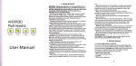
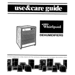
JT30
Wiring Diagram
115V WHITE
230V BLUE
1 15V BLACK
230V BROWN
POWE~
-:- GROUND: GREEN/YE.LOW
[BJ[Ig
I
1{1 RE:=RtGERA TlON
LiJ ON ;oF;:
I
WI
LQJ
CORD/PLUG
swtT CH
lr-ov_E.;...=I...;;L_c_A.:;.o_ _ _ _ _......,
e)'
I~s;>-+1---+-l '
THERMOSTAT
0
IN TE~P::::HURE
1
rolj
0
1
I
COMPRESSOR
Y-:-l_c_IR_c_ut_r_ _ _
H:-:~:-E_:.._A
... -~
C!..OSE:S ON RISE
.
0
~
~ [§
I_-""'
,.---
I
"----+--·-..;
51 ART CAFACITCR
(WZ5 ONLY l
r--
@]~------------
P----------------s:
,..~--------------~~
...::::...:
CENTE~
SPRAY
SWITCH
p.--------------r::
r--
r::::-~~1-----::l
u_Jr--~
t..:.._;
..:::._
_I
'
R!GHT SPRAY
SWITCH
~~:
D'.
OWG:
,--
~~-·---:::~
TERMINAL BOARD [ ]
CONNECTION
p--------------~Gi
WIRE MARKE::<
WZS &. W26 ONLY
I
18039 MODEL JT30 WIRING OI.A.GRAM REV 2
We reserve the right to make changes in design and/or engineering without notice.
Should the unit require service, take to nearest Jet authorized service center where parts
and service may be obtained (U.S.A. only).
8