1
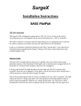
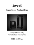
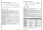
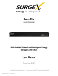
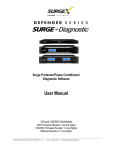
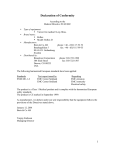
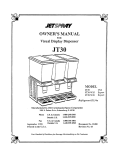
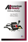
Defender Series Surge + PDU User Manual Congratulations on your SurgeX purchase and thank you for your business. Our Defender Series multi-stage protection technology will increase server uptime by protecting your equipment from dangerous power events that can disrupt or even destroy your investment. Your Defender Series Surge + PDU unit provides: • Failsafe protection: Shields server equipment from damaging surges, spikes, over voltage, EMI/RFI noise, and wire faults that can cause downtime, disruption, and equipment shutdown • Power distribution: A comprehensive Surge + PDU all-in-one solution • Redundancy: Extended protection for UPS and ancillary equipment and creates a stress free environment to keep your system up and running • Uptime: Helps increase uptime, protect data, extend equipment life and increase reliability of connected equipment Our goal is your complete satisfaction. Please visit surgex.com/defenderseries for additional product information, user manuals, warranty information, and product / warranty registration. Contact us at [email protected] for direct assistance. Thank you for your purchase! I. Product Description • Power Distribution Unit with multi-stage Surge Protection • Models: oSX-DS-L630-FP • 120/230 VAC Split Phase (North American) 24A Maximum Capacity 15A Maximum Capacity per Bank (1) NEMA L6-30P input power cord (6) IEC-320 C13 output power receptacles (2) 15A Branch-Rated Circuit Breakers oSX-DS-L530-FP • 120 VAC Single Phase (North American) 24A Maximum Capacity 15A Maximum Capacity per Bank (1) NEMA L5-30P input power cord (6) IEC-320 C13 output power receptacles (2) 15A Branch-Rated Circuit Breakers (6) IEC-320 C13 output power receptacles (2) 15A Branch-Rated Circuit Breakers oSX-DS-520-FP • 120V Single Phases (North America) 20A Maximum Capacity 10A Maximum Capacity per Bank (1) NEMA 5-20P input power cord © SurgeX REV-A Page 1 Defender Series Surge + PDU User Manual oSX-DS-IEC-FP • 220-240 VAC Single Phase (International) 32A Maximum Capacity 10A Maximum Capacity per Bank (1) IEC-60309 332P65 input power cord II. (6) IEC-320 C13 output power receptacles (3) 10A Branch Rated Circuit Breakers Hardware Included • Tower Configuration Hardware – Option A (1) Base stand (6) 6/32 x ½” Flathead Screws • Rack Mount Configuration Hardware – Option B (1) Left bracket (1) Right bracket (11) 6/32 x ¼” Flathead Screws (4) Thumbscrews (4) Cage Nuts • Cable Organizing Hardware (optional) (1) Cable Organizer III. (2) Thumbscrews (8) Plastic Ties Installation • Warning: Before installing the SurgeX Defender Series unit, review the safety instructions that came with the unit Unpack the Unit and Accessories oIdentify each item; refer to the Quick Start Guide for reference • Connect Cable Organizing Hardware (Optional) oUse (2) thumbscrews to attach the cable organizer to the rear panel (figure 1-a) • Configure Unit oSelect Tower or Rack Mount Configuration • Determine which configuration is best for your installation o Option A: For tower installations, the Defender Series Surge + PDU may be configured to mount upright as a Tower and can stand on any dry, flat surface o Option B: For rack installations, the Defender Series Surge + PDU may be configured to mount within a standard 19” equipment rack and will require 1 RU (Rack Unit) of space 1-a 2-a 2-b o © SurgeX REV-A Page 2 Defender Series Surge + PDU User Manual o To Install Tower Configuration – Option A • • Use a Phillips screwdriver and (6) 6/32 x ½” flathead screws to attach the base stand (figure 2-a) Place the Defender Series unit on a flat, stable surface in an upright position resting on the base stand (figure 2-b) 3-a o To Install Rack Mount Configuration – Option B • • • • • Use a Phillips screwdriver and (5) 6/32 x ¼” flathead screws to attach the left rack bracket (figure 3-a) Use a Phillips screwdriver and (6) 6/32 x ¼” flathead screws to attach the right rack bracket (figure 3-a) Insert the Defender Series unit into an available 1RU rack space from the front of the rack (figure 3-b) Product is designed for U-Space mounting only Use (4) thumbscrews to secure the left and right rack brackets to the rack rails (figure 3-b) Use (4) cage nuts to secure the 4 thumbscrews to the rack (figure 3-b) 3-b • Connect the Power Cables oConnect the ancillary server equipment power plugs to the IEC output power 4-a receptacles located on the rear panel of the Defender Series unit. Distribute the equipment load evenly between the receptacle banks (figure 4-a) oTo properly protect your system, connect all ancillary server equipment (including UPS/Battery Backup) to the SurgeX Defender Series output power receptacles; Refer to Common Configurations section for reference oCheck that the equipment you have connected to the Defender Series meets the following electrical rating requirements: • SX-DS-L630-FP: IMPORTANT: ONLY CONNECT EQUIPMENT RATED FOR USE WITH NORTH AMERICAN 120/230VAC SPLIT PHASE • SX-DS-L530-FP: IMPORTANT: ONLY CONNECT EQUIPMENT RATED FOR USE WITH NORTH AMERICAN 120VAC SINGLE PHASE • SX-DS-520-FP: IMPORTANT: ONLY CONNECT EQUIPMENT RATED FOR USE WITH NORTH AMERICAN 120VAC SINGLE PHASE • SX-DS-IEC-FP: IMPORTANT: ONLY CONNECT EQUIPMENT RATED FOR USE WITH 220240VAC SINGLE PHASE • Secure the Power Cables – (optional) oSecure equipment power cords to the cable organizer (if desired) using cable ties or zip ties, to prevent accidental removal (figure 5-a) © SurgeX REV-A 5-a Page 3 Defender Series Surge + PDU User Manual • Plug in the Power Cord oConnect the input power cord of the SurgeX Defender Series to AC Mains. Lock the SX-DS-L630-FP and SX-DSL530-FP plugs by turning to the right (figure 6-a) 6-a oDo not plug the unit into a UPS or re-locatable power tap; UPS devices should only be connected to the SurgeX Defender Series unit • Check Front Panel oCheck the front panel to make sure the green “Outlets On” LED is lit • If the green “Outlets On” LED is lit, your Defender Series unit is ready to be used, and is protecting your server and ancillary equipment (figure 7-a) oIf the green “Outlets On” LED is not lit, but the red Wiring Fault Indicator LED is lit, a wiring fault at the outlet has been detected. The SurgeX unit will not operate until the Wiring Fault is resolved by a qualified electrician. Refer to the “Front Panel LED Indicators” section for further instructions (figure 7-b) IV. 7-a 7-b Common Configurations • To properly protect your system, connect all ancillary server equipment (including UPS/Battery Backup) to the SurgeX Defender Series output power receptacles (figure 8-a) 8-a © SurgeX REV-A Page 4 Defender Series Surge + PDU User Manual V. Front Panel LED Indicators • Power Indicator (Green); the green Power Indicator LED located on the left/top of the front panel indicates that the electrical AC Mains is properly wired, and power is available at the output power receptacles (figure 9-a) • Wiring Fault Indicator (Red); the red Wiring Fault Indicator LED located to the right/ below the green Power Indicator LED on the front panel indicates that the electrical AC Mains is not properly grounded, and power is not available at the output power receptacles (figure 9-b) oIf the red Wiring Fault indicator LED is illuminated, contact a licensed electrician to inspect the electrical AC source outlet and repair as necessary oSX-DS-L530-FP model only: The red Wiring Fault Indicator LED may also indicate that the electrical AC Mains is improperly wired with the Line and Neutral conductors reversed, and power is not available at the output power receptacles • 9-a 9-b IMPORTANT: The presence of a safety Ground is essential to reduce the risk of electric shock. If the red Wiring Fault indicator LED is illuminated, contact a licensed electrician to inspect the AC power source / outlet and repair as necessary. VI. Over Voltage Conditions • In the event of a long duration over-voltage condition, the unit will stop passing power to connected equipment until the voltage returns to a safe operating level; this function is designed to protect your system VII. Other Information You May Need • Warning: See the safety and regulatory information that is shipped with your Defender Series unit. Warranty information may be included within this document or as a separate document. oThe User Manual provides information about product features and describes how to install and troubleshoot the unit; this document is available online at surgex.com/defenderseries oThe Quick Start guide that is shipped with your Defender Series unit describes how to install your system; this document is available online at surgex.com/defenderseries oThe Safety Guide that is shipped with your Defender Series unit describes all safety and regulatory information; this document is available online at surgex.com/defenderseries oNote: Always check for updated materials at surgex.com/defenderseries and read through these updated materials first, because it may supersede information in other documents • VIII. © SurgeX Service Kits for replacement mounting hardware can be obtained by ordering Part #SX-DS-SK-MH Technical Assistance • If you do not understand these instructions or if the unit does not perform as expected, visit surgex.com/ defenderseries or email [email protected] for further assistance REV-A Page 5 Defender Series Surge + PDU User Manual IX. Specifications SX-DS-L630-FP SX-DS-L530-FP SX-DS-520-FP SX-DS-IEC-FP Voltage Rating 120/230 Volts Split Phase 120 Volts Single Phase 120 Volts Single Phase 220-240 Volts Single Phase Frequency 50/60 Hz 50/60 Hz 50/60 Hz 50/60 Hz Load Rating 24 Amp Maximum Capacity 24 Amp Maximum Capacity 20 Amp Maximum Capacity 32 Amp Maximum Capacity Input Connector NEMA L6-30P NEMA L5-30P NEMA 5-20P IEC-60309 332P65 Output Connector (6) IEC-320 C13 (6) IEC-320 C13 (6) IEC-320 C13 (6) IEC-320 C13 Overload Protection (2) Circuit Breaker (2) Circuit Breaker (2) Circuit Breaker (3) Circuit Breaker Voltage Protection Rating (VPR) 800V Line - Line 500V Line - Ground 330V All Modes 330V All Modes 800V Line - Line 500V Line - Ground Power Requirement (no load) 8 Watts 8 Watts 8 Watts 8 Watts Attenuation Normal Mode: >30dB 50kHz - 50MHz Common Mode: >30dB 150kHz - 50MHz Normal Mode: >30dB 50kHz - 50MHz Common Mode: >30dB 50kHz - 50MHz Normal Mode: >30dB 50kHz – 50MHz Common Mode: >30dB 50kHz – 50MHz Normal Mode: >30dB 50kHz - 50MHz Common Mode: >30dB 150kHz - 50MHz Over-Voltage Shutdown 280 Volts (±2%) Restores at 260 Volts (±2%) 150 Volts (±2%) Restores at 135 Volts (±2%) 150 Volts (±2%) Restores at 135 Volts (±2%) 280 Volts (±2%) Restores at 260 Volts (±2%) Response Time 100 msec Over-Voltage 100 msec Over-Voltage 100 msec Over-Voltage 17.44” W x 12.08” D x 1.71” H (1 RU) 100 msec Over-Voltage Dimensions 17.44” W x 12.08” D x 1.71” H (1 RU) 17.44” W x 12.08” D x 1.71” H (1 RU) 17.44” W x 12.08” D x 1.71” H (1 RU) Weight 12.5 lb 12.5 lb 12.5 lb 12.5 lb Input Cord Length 3m 3m 3m 3m Rack Mounting Hardware Included Included Included Included Standalone Hardware Included Included Included Included Power Indicator LED (Green) LED (Green) LED (Green) LED (Green) Wiring Fault Indicator LED (Red) Illuminated when no protective Earth Ground present LED (Red) Illuminated when no protective Earth Ground present or when Line/Neutral reversed LED (Red) Illuminated when no protective Earth Ground present or when Line/Neutral reversed LED (Red) Illuminated when no protective Earth Ground present BTU/h 100 BTU/h Maximum at full rated load 100 BTU/h Maximum at full rated load 100 BTU/h Maximum at full rated load 140 BTU/h Maximum at full rated load Temperature Range 5°C to 40°C 5°C to 40°C 5°C to 40°C 5°C to 40°C Humidity Range 5% to 95% R.H. Noncondensing 5% to 95% R.H. Noncondensing 5% to 95% R.H. Noncondensing 5% to 95% R.H. Noncondensing Agency Listings TUV Certified to UL 60950-1 Check surgex.com/ defenderseries for country specific certifications TUV Certified to UL 60950-1 Check surgex.com/ defenderseries for country specific certifications TUV Certified to UL 60950-1 Check surgex.com/ defenderseries for country specific certifications CE/CB Check surgex.com/ defenderseries for country specific certifications Specifications subject to change without notice All listed specifications obtained at an ambient temperature of 25° © SurgeX REV-A Page 6