1
Pre-Installation
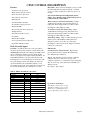
GENERAL INFORMATION
Installation, operation and maintenance instructions
are provided with each unit. Before unit start-up, read
all manuals and become familiar with the unit and its
operation. Thoroughly check the system before operation.
Prepare units for installation as follows:
1. Compare the electrical data on the unit nameplate
with ordering and shipping information to verify the
correct unit has been shipped.
2. Keep the cabinet covered with the shipping carton
until installation is complete and all plastering,
painting, etc., is finished.
3. Verify refrigerant tubing is free of kinks or dents and
that it does not touch other unit components.
4. Inspect all electrical connections. Connections must
be clean and tight at the terminals.
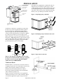
Remove Fan Motor shipping bracket in rear of
Air Handler compartment.
To avoid equipment damage, DO NOT use these
units as a source of heating or cooling during the
construction process. The mechanical components
and filters used in these units will quickly become
clogged with construction dirt and debris which
may cause system damage.
To avoid the release of refrigerant into the
atmosphere, the refrigerant circuit of this unit
must be serviced only by technicians who meet
local, state and federal proficiency requirements.
All refrigerant discharged from this unit must be
recovered WITHOUT EXCEPTION. Technicians
must follow industry accepted guidelines and all
local, state and federal statutes for the recovery
and disposal of refrigerants.
If a compressor is removed from this unit,
system refrigerant circuit oil will remain in the
compressor. To avoid leakage of compressor oil,
the refrigerant lines of the compressor must be
sealed after it is removed.
The installation of geothermal heat pump units and all
associated components, parts and accessories which
make up the installation shall be in accordance with
the regulations of ALL authorities having jurisdiction
and MUST conform to all applicable codes. It is the
responsibility of the Installing Contractor to determine and
comply with ALL applicable codes and regulations.
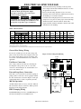
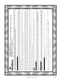
VTPhysicalData
Table 1: Physical Data
MODEL
FanWheel(Dia.XWidth),in.
036
9X7
FanMotor&HP
ECM-1/2
Compressors
2-Rotary
No.RefrigerantCircuits
No.CoaxialHeatExchangers
2
2
042
048
060
11X10
ECM-1/2
2
2
ECM-1
2-Scroll
072
11X10
2
2
2
2
ECM-1
2-Scroll
2
2
R-22Charge(SysA/SysB),oz
40/40
57/59
62/62
54/54
58/58
AirCoilLengthxHeight,in.
20X24
24X24
24X32
24X36
24X36
Filter-1"ElectroStatic(Std.)
24x24
27x31
27x31
27x35
27x35
235
285
315
395
WaterConnectionSize(fptswivel)
Weight-Operating(lbs.)
Weight-Packaged(lbs.)
1"
225
1"
275
1"
305
385
1"
450
460
Rev.:8/07/04D
Allunitshavetxvexpansiondevices,20gasheetmetal,
and7/8"&1-1/8"electricalknockouts.
Allunitshavedual1"Swivelwaterconnections(4total)
HWGutilizes1/2"fptwaterconnectionsandisavailableonlyoncircuitA.
Allunitshave3/4"fptcondensatedrainconnections.
Ultra Classic (VT) Series
Revision
1"
Page Date