1
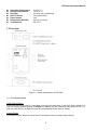
STE100A Single Port IP to Serial Device Server CTC Union Technologies Co., Ltd. Far Eastern Vienna Technology Center (Neihu Technology Park) 8F, No. 60 Zhouzi St., Neihu, Taipei 114, Taiwan T +886-2-26591021 F +886-2-26590237 E [email protected] [email protected] [email protected] H www.ctcu.com STE100A Operation Manual Single Port IP to Serial Device Server Version 1.4 May 3, 2013 (Update) 2010-2013 CTC Union Technologies Co., LTD. All trademarks are the property of their respective owners. Technical information in this document is subject to change without notice. Legal The information in this publication has been carefully checked and is believed to be entirely accurate at the time of publication. CTC Union Technologies assumes no responsibility, however, for possible errors or omissions, or for any consequences resulting from the use of the information contained herein. CTC Union Technologies reserves the right to make changes in its products or product specifications with the intent to improve function or design at any time and without notice and is not required to update this documentation to reflect such changes. CTC Union Technologies makes no warranty, representation, or guarantee regarding the suitability of its products for any particular purpose, nor does CTC Union assume any liability arising out of the application or use of any product and specifically disclaims any and all liability, including without limitation any consequential or incidental damages. CTC Union products are not designed, intended, or authorized for use in systems or applications intended to support or sustain life, or for any other application in which the failure of the product could create a situation where personal injury or death may occur. Should the Buyer purchase or use a CTC Union product for any such unintended or unauthorized application, the Buyer shall indemnify and hold CTC Union Technologies and its officers, employees, subsidiaries, affiliates, and distributors harmless against all claims, costs, damages, expenses, and reasonable attorney fees arising out of, either directly or indirectly, any claim of personal injury or death that may be associated with such unintended or unauthorized use, even if such claim alleges that CTC Union Technologies was negligent regarding the design or manufacture of said product. TRADEMARKS Microsoft is a registered trademark of Microsoft Corp. HyperTerminal™ is a registered trademark of Hilgraeve Inc. WARNING: This equipment has been tested and found to comply with the limits for a Class A digital device, pursuant to Part 15 of the FCC Rules. These limits are designed to provide reasonable protection against harmful interference when the equipment is operated in a commercial environment. This equipment generates, uses, and can radiate radio frequency energy and if not installed and used in accordance with the instruction manual may cause harmful interference in which case the user will be required to correct the interference at his own expense. NOTICE: (1) The changes or modifications not expressively approved by the party responsible for compliance could void the user's authority to operate the equipment. (2) Shielded interface cables and AC power cord, if any, must be used in order to comply with the emission limits. Table of Contents Chapter 1 Introduction....................................................................................................................... 7 1.1 Welcome .................................................................................................................................. 7 1.2 Product Description.................................................................................................................. 7 1.3 Features................................................................................................................................... 7 1.4 Specifications........................................................................................................................... 7 1.5 Overview .................................................................................................................................. 8 1.5.1 Load Default Button .......................................................................................................... 8 1.5.2 LED Indicators................................................................................................................... 9 1.6 Quick Guide to Installation and Management .......................................................................... 9 1.7 Interfaces ................................................................................................................................. 9 1.8 Typical Applications ............................................................................................................... 11 Chapter 2 Operation........................................................................................................................ 13 2.1 Getting Started....................................................................................................................... 13 2.2 Setup IP Address ................................................................................................................... 13 Chapter 3 Web Management .......................................................................................................... 14 3.1 Login Page............................................................................................................................. 14 3.2 Administrator.......................................................................................................................... 15 3.3 TCP Mode.............................................................................................................................. 18 3.3.1 Telnet Server................................................................................................................... 18 3.3.2 Telnet Client .................................................................................................................... 18 3.3.3 Reverse Telnet................................................................................................................ 19 3.3.4 CLI Mode......................................................................................................................... 19 3.3.5 Port Number.................................................................................................................... 19 3.3.6 Remote Server IP Address ............................................................................................. 19 3.3.7 Client mode inactive timeout ........................................................................................... 19 3.3.8 Server mode protect timeout........................................................................................... 19 3.4 UDP Mode ............................................................................................................................. 20 3.4.1 Mode ............................................................................................................................... 20 3.4.2 Local Port ........................................................................................................................ 21 3.4.3 Remote Address ............................................................................................................. 21 3.5 UART ..................................................................................................................................... 21 3.6 Reset Device.......................................................................................................................... 22 Chapter 4 VCOM............................................................................................................................. 23 4.1 Installing Vcom....................................................................................................................... 23 4.2 Broadcast Search .................................................................................................................. 29 4.3 Configuration.......................................................................................................................... 31 4.4 COM Mapping........................................................................................................................ 33 STE100A Operation Manual Chapter 1 Introduction 1.1 Welcome Thank you for choosing the STE100A Single Port IP to Serial Device Server. If you would like to skip right to the operation of this converter, proceed to Chapter 2. This manual is used to explain the hardware installation procedures and operation of the STE100A, and present its capabilities and specifications. This manual is divided into 4 Sections, the Introduction, Installation, Operational, plus the Vcom application program (virtual COM) installation and usage. 1.2 Product Description The IP Serial Server provides the serial device server for Windows hosts to control serial devices located virtually anywhere through TCP/IP or UDP/IP Ethernet connection. The IP Serial Server has the asynchronous RS-232 serial port connection on one side, and a 10/100 Mbps Ethernet connection on the other side. IP Serial Server can function in a UDP environment or as server or client for TCP connections. The application scenarios include direct IP mode, Virtual COM mode and paired mode. When in the paired mode one IP Serial Server will be set as a client while the other will act as a server for TCP connection. 1.3 Features z z z z z z z z 10/100Mbps Ethernet port 230.4kbps serial interface maximum baud rate TCP Server, TCP client, Virtual com mode, UDP Normal, UDP Listen Supports DHCP (client), HTTP (web management), ICMP, ARP, IP, UDP, TCP Easy to use with Windows® Virtual Com utility, Vcom Configuration by web browser Compact size 53x85x21(mm) Low power consumption with single + 12V to +48V input 1.4 Specifications General LED Push button OS supported Serial Interface Serial Connector Baud rate Data bits Stop bits Parity Flow Control Data Packing Delimiter LAN Interface Ready, TP Link/Act, RS232 Tx/Rx For Load Default Configuration and Reset System Windows® XP/2000/2003/2008/Vista/Win7/Win8 (for Vcom) RS-232 DB-9 male 110 to 230.4Kbps 5, 6, 7, 8 1, 1.5 for Data bits 5 mode; 1, 2 for data bits 6, 7, 8 mode None, Even, Odd, Space, Mark None, Hardware (RTS/CTS) 1,2 RJ-45 connector, IEEE802.3 10/100BaseT, Auto-negotiation, Full/Half-duplex Communication Modes TCP Server, TCP Client, Virtual COM mode, UDP Normal, UDP Listen Protocols TCP, UDP, IP, ARP, ICMP, HTTP, DHCP, ICMP Client requests connection at Power up TCP Inactivity Timeout (TCP alive time) Management Web, Firmware upgradeable Security Password Access Power DC Input, 12 to 48 VDC 7 STE100A Operation Manual Operating Temperature Storage Temperature Humidity DIN rail mount Panel mount Dimensions (WxDxH) Certifications 0 to 60 °C -10 to 70 °C 0 to 90% non-condensing Yes (optional kit) Yes 53 x 85 x 21(mm) CE, FCC 1.5 Overview Figure 1.1 Panel designations of STE100A 1.5.1 Load Default Button Load Default Setting Press and hold this button for more than 3 seconds but less than 10 seconds, then release it to load the factory default settings. STE100A IP address will be restored to the default of 10.1.1.1 with net mask 255.0.0.0. Both the login ID and password will be reset to “admin”. System Reset Press and hold this button for more than 10 seconds to force a system reset (reboot). 8 STE100A Operation Manual 1.5.2 LED Indicators LED Name Ready Link/Act Tx/Rx Status On Off On Blinking Off Blinking Off Description Power is on and the device is ready. Power is off or the device is not ready. UTP is link. UTP Tx/Rx is activity. UTP is not link. RS-232 port is transmitting or receiving data. No data is transmitting or receiving in RS-232 port. 1.6 Quick Guide to Installation and Management There are two methods to install and manage STE100A. Installation and Management by Web Browser Step 1: Plug in the power adaptor, connect this serial device server to Ethernet. Step 2: Press and hold the load default button for more than 3 seconds and less than 10 seconds, then release it. This will return the serial device server to factory default and it will respond to the IP address 10.1.1.1. Step 3: The user may configure the PC to the same IP domain, use web browser to link with http://10.1.1.1 to manage it. The default login ID will be “admin” and the password will be “admin”. Step 4: The user configures this serial device server by web browser according to their application. Step 5: User may change this serial device server IP by web browser, too. After changing its IP address, the IP Server needs to do a system reset (or repower). Installation and Configuration by Virtual COM Application Step 1: Plug in the power adaptor, connect this serial device server to Ethernet. Step 2: Find the Virtual COM Windows® application in CD, install it. Step 3: Use the Virtual COM application to locate the serial device server unit. Step 4: After the device is found, user may configure this serial device server by Virtual COM Windows® application according to their application. 1.7 Interfaces RJ45 Ethernet Pin Assignments Pin 1 2 3 6 Name TX+ TXRX+ RX- RS-232 DB9 Male Pin Assignment Pin 1 2 3 4 5 6 7 8 Name DCD RD TD DTR GND DSR RTS CTS I/O Input Input Output Output Input Output Input 9 STE100A Operation Manual This serial device server performs as a DTE device. It needs to use an RS-232 cross cable to connect both PC and this unit; z Connect the STE100A to PC or DTE device without hardware flow control feature. PC or DTE Device RS-232 X-over cable TD RD GND z STE100A RD TD GND Connect the STE100A to PC or DTE device with hardware flow control feature. PC or DTE Device RS-232 X-over cable TD RD RTS CTS DSR DTR GND STE100A RD TD CTS RTS DTR DSR GND STE100A needs to use a straight cable to connect a DCE device and this unit. z Connect the STE100A to DCE device without hardware flow control feature. DCE Device TD RD GND z STE100A RS-232 1:1 cable TD RD GND Connect the STE100A to DCE device with hardware flow control feature. DCE Device RS-232 1:1 cable TD RD RTS CTS DSR DTR GND STE100A TD RD RTS CTS DSR DTR GND 10 STE100A Operation Manual 1.8 Typical Applications z UDP PC STE100A RS-232 10/100 Base-T/TX UDP Normal mode PC RS-232 STE100A STE100A PC RS-232 UDP Normal mode 10/100 Base-T/TX STE100A Device RS-232 UDP Normal mode UDP Listen mode STE100A RS-232 Device UDP Normal mode STE100A RS-232 Device UDP Normal mode z TCP Server (Telnet Server) / TCP Client (Telnet Client) Device STE100A RS-232 10/100 Base-T/TX TCP Client Mode PC STE100A RS-232 STE100A RS-232 TCP Server Mode 10/100 Base-T/TX PC TCP Server Mode TCP Client Mode Device RS-232 STE100A 10/100 Base-T/TX TCP Server Mode 11 PC TCP Client Mode Device STE100A Operation Manual z VCOM The purpose of VCom is to make the virtual COM port exhibit behavior that closely resembles that of a "real" COM port, i.e., a COM port driver for local serial port hardware. User applications use the VCom COM port redirector through one or more virtual COM ports that the redirector creates, as configured by the user. When the application opens the virtual COM port, VCom makes an IP network connection to the STE100A server at the specified IP address and TCP/UDP port number that corresponds to the remote device on the server. The COM port redirector then begins relaying the application data stream between the virtual COM port and the device server. The VCom serial port redirector for Windows® is configured using a control-panel style graphical user interface for creating virtual COM ports, configuring settings for individual COM ports, and configuring global settings affecting all COM ports. The VCom GUI also includes displays of virtual COM port activity and various diagnostic aids. VCom allows legacy serial programs that access the PC communications ports (COM1, COM2, etc.) to access the STE100A by IP address, just as if it were an actual communications port. PC Device STE100A RS-232 10/100 Base-T/TX TCP Server Mode VirtualCOM Application PC COM: Ethernet COM2: Application VCOM TCP Client Mode The equivalent software for a Unix/Linux operating system is commonly called a tty port redirector. A number of open source projects exist for port redirection. Below are just a few of the more popular projects. com0com project (Windows) netfwd (BSD) remserial (Linux) serproxy (Linux, Windows) socat project (Linux) ser2sock.c (Linux, BSD) 12 STE100A Operation Manual Chapter 2 Operation 2.1 Getting Started This section describes how to connect the STE100A to serial devices for the first time testing purposes. Connecting to the Power Connect STE100A to the 12 to 48 VDC power source. The STE100A is shipped with an AC switching power adapter with 12VDC output voltage. If the system is ready, the “Ready” LED will be lit. Connecting to the Network Connect the STE100A to the Ethernet network. The STE100A will indicate a valid Ethernet copper connection in the following ways: 1. The Link/Act LED will be turned on when the UTP is in link stage. 2. The Link/Act LED will be blinking when the UTP is transmitting or receiving data packets. Connecting to the Serial Device Connect the RS-232 serial cable between STE100A and the serial device. This serial device server performs as DTE device and needs to use an RS-232 cross-over cable if connecting to a PC. The STE100A uses a straight cable to connect to DCE devices, such as a modem. 2.2 Setup IP Address Factory Default IP Address Press and hold the load default button for more than 3 seconds and less than 10 seconds, then release it. This will default the serial device server so that the IP address is 10.1.1.1. Setup IP Address by Web Page User may use web browser and link to STE100A web page. After logging in with the default username/password of ‘admin/admin’, the user can change this serial device server IP address and other configuration parameters. After changing its IP address, the STE100A needs to do system reset or repower. Setup IP address by VCOM Application User may install VCOM windows application, and use it to locate the serial device server unit. After this device is found, user may configure this serial device server by VCOM Windows® program according to your application. Please refer to Chapter 4. 13 STE100A Operation Manual Chapter 3 Web Management 3.1 Login Page User must configure the PC to the same default IP domain as STE100A, then use web browser to link to the STE100A IP address and manage it. The STE100A home page will be a login window. The default login ID is “admin” and the password is “admin”. If user forgets the login ID and password, please refer to section 1.5.1 to load default settings. After login, user can see the Administrator, TCP Mode, UDP Mode, UART Mode, and Reset Device selection in left frame of web page. We will describe their operation in the following sections. There is an 'idle time' auto logout feature. The default is 5 minutes and it can be adjusted from 1~99 minutes. 14 STE100A Operation Manual 3.2 Administrator Under the ‘Administrator’ heading, the user will be able to set/change the device password, configure the networking parameters, display the current firmware version, load the factory defaults, and perform any future firmware upgrade procedure. 3.2.1 Authentication In this page, user can change login ID and Password. STE100A supports a maximum of 15 characters for password. Only the "0-9","a-z","A-Z" characters are allowed. Press "Update" to store data. Reset the device to take effect. 3.2.2 System IP On this page, the user may change the system network configuration. If the IP Configure field is set to DHCP mode, all the other settings will be ignored, and the IP address will be assigned by DHCP server after resetting the device. Press "Update" to store data. Reset the device to take effect. 15 STE100A Operation Manual 3.2.3 System Status On this page, the user can display the system information as below: Kernel version: Kernel firmware version and build date. MAC Address: MAC address of this unit. Target Name: Device alias name. (The maximum length is 12 characters.) Only the "0-9","a-z","A-Z","_" (underscore),and "-" (dash) characters are allowed. The 'idle time security' is an auto logout feature. It can be adjusted from 1~99 minutes Press "Update" to store the ‘Target Name’ and 'Idle Time' data, and then, STE100A will reset to take effect. 3.2.4 Load default setting On this page, user may load and store the factory default setting into EEPROM. However, the Network settings and MAC address will not be changed. Press "Load" to load default settings. WARNING: Pressing the ‘Load Default’ button will immediately erase the flash with no further warning!! Reset the device to take effect. 16 STE100A Operation Manual 3.2.5 Firmware update On this page, user can update the firmware via Ethernet. Step 1: Pressing the "Load" button will erase settings in flash. Step 2: Wait for erase process to complete. Processing please wait.... Step 3: Firmware Update by TFTP or Web. There are two methods to do the Firmware Update action: 1. (By Web) Please type in or browse for the target image file in the input field, and then press "update" button to continue. 2. (By TFTP client) Use MS Windows' Command Prompt window to run tftp client program. Syntax: c:\tftp -i 10.1.1.1 put FILE_DIRECTORY\FILENAME.bin 3. If the update process somehow goes wrong (like power failure), please connect to http://10.1.1.1 to restart. (If possible, reset device first.) 4. It takes about 45 seconds to complete the firmware update. You must be careful when performing this update procedure, to prevent any unexpected problem occurring. 17 STE100A Operation Manual 3.3 TCP Mode When TCP mode is set to Server or Client mode, the UDP mode will be disabled automatically. When UDP mode is enabled, the TCP mode will be disabled automatically. 3.3.1 Telnet Server Set the device to be a Telnet Server. In this case the Ethernet connected device is a Telnet client. In server mode, the Telnet port listens and waits for a host or other client to make a connection 3.3.2 Telnet Client Set the device to be a Telnet Client. In the case the Ethernet connected device is a Telnet server or other STE100A in server mode. 18 STE100A Operation Manual 3.3.3 Reverse Telnet Reverse Telnet works the same as Telnet Server mode. The Telnet port listens for a connection after booting up. When the user uses some Telnet clients that sometimes have errors, such as devices connected to the Microsoft interpretation of Telnet of Windows XP, then, user should choose Reverse Telnet mode. 3.3.4 CLI Mode The Command Line Interface (CLI) allows user to configure and control STE100A directly through the UART interface. The CLI mode is only available when STE100A is in TCP Server Mode. 3.3.5 Port Number This assigns the TCP server port number that the server will listen on for connecting clients. (Only for Server Mode) 3.3.6 Remote Server IP Address When in Client mode, this device will automatically try to connect to the remote TCP server with this IP address.(Only for Client Mode) 3.3.7 Client mode inactive timeout When in Client mode, this parameter sets the time that device will maintain a connection until timeout, if there is no data transfer over the connection. After disconnecting, the device will try to build a new connection again immediately. 3.3.8 Server mode protect timeout When in Server mode, this parameter sets the time that device will maintain a connection until timeout, if there is no data transfer over the connection. Once disconnected, only a Client can initiate a new connection to the Server. Note: After setting, press “Update” to store setting and then reset the device to take effect. 19 STE100A Operation Manual 3.4 UDP Mode When the UDP mode is enabled, the TCP mode will be disabled automatically. In this UDP mode, the Local Port will be assigned to this device. User can list the remote connection IP and Port of devices, for up to 10 remote devices. 3.4.1 Mode Listen : When this device is in UDP listen mode, it can only receive remote UDP data. Normal : When this device is in UDP normal mode, it can both receive and send UDP data to remote units. 20 STE100A Operation Manual 3.4.2 Local Port Assign the UDP port here that this unit listens on. 3.4.3 Remote Address The remote address table allows users to set several remote site IP addresses and ports. When sending data, the device will send UDP data to the IP addresses of the table. Note: After setting, press “Update” to store settings. The device needs to reset for the settings to take effect. 3.5 UART UART or Universal Asynchronous Receiver Transmitter refers to the ‘RS-232 serial port’ of the STE100A IP Serial Server. All of the port settings are done from this page. RS-232 port setting page 21 STE100A Operation Manual Baud rate Set the baud rate of UART interface. The STE100A supports 110, 300, 1200, 2400, 4800, 9600, 19200, 38400, 57600, 115200 and 230400 baud rates. Character Bits Set the number of data length of UART interface. The STE100A supports character bits of 5, 6, 7, or 8 bits. Parity Type Set the parity of UART interface. The STE100A supports parity settings of Odd, Even, Space, Mark or none. Stop Bit Set the stop bit length of UART interface. The STE100A supports 1, 1.5 or 2 stop bits. Hardware Flow Control Set the flow control mode of UART interface as enabled or as none. UART Memory Overflow count Show the message about the number of overflow bytes in network buffer. UART FIFO Overflow count Show the message about the number of overflow times in UART RX buffer. Delimiter This sets the Character 1 and/or Character 2 to be used as the delimiter. Once the system detects the delimiter value of data received from UART, the data in the network buffer will be sent out by Ethernet. The Drop Character is set to drop delimiter or not of send out data. Silent time sets the time that system will check for how long no data has been received from UART. If this condition is enabled, system will send out data stored in network buffer to network once this condition is true or the received data will only be stored in network buffer. Note: After setting, press “Update” to store settings. The device needs to reset for the settings to take effect. 3.6 Reset Device Pressing the “Reset” button will force the STE100A to do system reset action. 22 STE100A Operation Manual Chapter 4 VCOM VCom lets you install and configure your STE100A easily over the network. Five function groups are provided to ease the installation process, allow COM mapping, and provide monitoring and IP location server functions. (Note for Windows 8 users. You must install the latest 4.1.3 version of WinPcap from the install CDROM or go to www.winpcap.org to download and install latest version first.) 4.1 Installing Vcom 1. Autorun - In most cases, Windows default security settings will no longer let an inserted CD or DVD execute the autorun program. If a popup window does display, choose the option to open the files in a folder. Located on the CD will be three folders. The "documents" folder will contain the STE100A user manual in PDF format and possibly other application notes. The "Install_Me_First" folder contains the WinPCap setup program, while the "Install_Me_Second" folder has the actual Vcom setup program. 23 STE100A Operation Manual 2. First install WinPcap; double-click into the "Install_Me_First" folder. Run the setup program for WinPCap by double clicking it. This program, which is also required of packet capture programs such as Wireshark, will allow the Vcom program to access your PC NIC (Network Interface Card) and to discover and communicate with access units located on your local subnet. If the PC already has this version of WinPcap or newer, this step may be skipped. 24 STE100A Operation Manual To continue setting up, click "Next" on the setup wizard Click "I Agree" to the license terms of the WinPcap program. By default, the WinPcap driver will start automatically each time Windows boots. We recommend leaving this option checked. 25 STE100A Operation Manual The setup program will run its course. At the completed window, click "Finish". 3. Setup Vcom - Return back to the root folder of the CD and this time, double-click into the "Install_Me_Second" folder. 26 STE100A Operation Manual This folder contains the Vcom setup program, "vcomsetup". Double-click this file icon to start Vcom setup. The setup files will be extracted in preparation for starting the actual setup program for Vcom. 27 STE100A Operation Manual At the "Welcome" screen, click "Next". The "Progress Bar" will indicate the status of installation. When Vcom has finished installing, close this window by clicking the "Finish" button. 28 STE100A Operation Manual The final action of the Vcom installer will be to try to install the WinPcap application. Because this embedded program is an older version (4.1.1), a "Newer Version" popup will appear. Click the "OK" button to keep the 4.1.3 version previously installed. This 4.1.3 version of WinPcap is required for Vcom to run on Windows 8. Click OK to abort the WinPcap setup for 4.1.1 It is probably a very good idea to reboot your PC now. This will ensure that the WinPcap driver is loaded and running and that Vcom has automatically started. 4.2 Broadcast Search The Broadcast Search function is used to locate all STE100A that are connected to the same LAN as your computer. Since the Broadcast Search function searches by MAC address and not IP address, all STE100A connected to the LAN will be located, regardless of whether or not they are part of the same subnet as the host. 1. Click Search button. 29 STE100A Operation Manual The very first time that Vcom searches the network for STE100A, a "Windows Security Alert" will popup as Vcom accesses the network. To allow Vcom access through the Windows firewall, click the button labeled "Allow Access". 2. All STE100A connected to the local LAN will be found. 30 STE100A Operation Manual 4.3 Configuration 1. Click the device that you want to configure. (Note: The IP address of STE100A must be on the same subnet as Vcom PC's IP subnet.) 2. Click the Configure button, then input account name and password; Press the OK button. Important notice: The STE100A must have a password set in order to be managed via Vcom. Vcom is unable to handle "null password". If a null password was set via the STE100A web interface, the device must be again accessed by web interface and have a password set. Then Vcom will be able to login and access the STE100A. 31 STE100A Operation Manual 3. Configure the device and press OK button. (Device configuration settings are explained in the Web Management Chapter 3.) 32 STE100A Operation Manual 4.4 COM Mapping 1. Click COM Mapping. 2. Click Add button and wait for while. 33 STE100A Operation Manual 3. Click OK button to create com mapping. Item TCP/UDP Server/Client IP Address Local Port COM Description Network Protocol You must choose a side if you choose TCP TCP Server: Disabled TCP Client: Remote Server Address UDP : Remote Target Address Listen port Virtual Com port 34