1
Installation Manual
FGC Communication Module
Table of Contents
Table of Contents
Read This First.........................................................................................................................................3
Introduction..........................................................................................................................................3
Product Documentation..................................................................................................................... 3
Safety Regulations for Owner/Operator...........................................................................................3
Guarantee.............................................................................................................................................3
This Manual.......................................................................................................................................... 3
Communication Options.......................................................................................................................5
Introduction..........................................................................................................................................5
SMS Messaging................................................................................................................................... 5
Dialled Communication......................................................................................................................5
Fixed Line Communication................................................................................................................ 5
MTC-COM............................................................................................................................................ 6
Installation............................................................................................................................................... 7
Introduction..........................................................................................................................................7
Installing the Module.......................................................................................................................... 7
Technical data....................................................................................................................................10
Communication Configuration.......................................................................................................... 11
Introduction....................................................................................................................................... 11
Configuring SMS Messaging........................................................................................................... 11
Configuring Dialled Line.................................................................................................................. 11
Configuring Fixed Line..................................................................................................................... 13
Alarm Configuration............................................................................................................................ 14
Introduction....................................................................................................................................... 14
Configuration Options - Alarms Sent as SMS................................................................................ 14
Configuration Options - Alarms Sent to SCADA System............................................................. 15
Alarm Operation.................................................................................................................................. 16
Introduction....................................................................................................................................... 16
Disabling Alarms Temporarily......................................................................................................... 16
Receiving Alarms Sent as SMS.........................................................................................................16
Acknowledge Alarms Sent as SMS................................................................................................. 16
Flygt SCADA System (AquaView)...................................................................................................... 17
Status.................................................................................................................................................. 17
Set Points............................................................................................................................................18
Report................................................................................................................................................. 18
Trend...................................................................................................................................................18
Other SCADA Systems........................................................................................................................ 20
Introduction....................................................................................................................................... 20
Status.................................................................................................................................................. 20
Alarm Handling (Dialup)...................................................................................................................22
Max Buffer Size (Advanced Settings).............................................................................................. 22
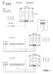
Appendix A: Configuring a Modem..................................................................................................24
Introduction....................................................................................................................................... 24
Example of a TD-33 Modem............................................................................................................24
FGC Communication Module Installation Manual
1
Table of Contents
Appendix B: Tag List............................................................................................................................25
Appendix B: Tag List.........................................................................................................................25
Appendix C: FGC Versions.................................................................................................................27
Introduction....................................................................................................................................... 27
Differences in Communication Functionality................................................................................ 27
2
FGC Communication Module Installation Manual
Read This First
Read This First
Introduction
Before any installation or configuration, read this chapter carefully. It contains general
information on documentation, safety and guarantee.
Product Documentation
This manual describes the configuration when the communication module is used in an
FGC 313/323.
If the communication module is used in an FGC series I or FGC Series II, there are
limitations and differences, see Appendix C: FGC Versions (page 27).
For a complete list of FGC menus and their default values, refer to the FGC User manual.
Safety Regulations for Owner/Operator
• All government regulations, local health and safety directives must be observed.
• All danger due to electricity must be avoided.
Guarantee
• Modifications or changes to the unit/installation should be carried out only after
consulting Xylem.
• Original spare parts and accessories authorized by the manufacturer are essential for
compliance with the terms of the guarantee. The use of other parts may invalidate any
claims for warranty or compensation.
This Manual
This manual is applicable to the following versions:
FGC Communication Module:
• Hardware: 1.00
• Software: FC 1.50, or later
FGC:
• Main board: 1.02, 1.03, 2.02,
2.03, 2.04, 2.05, 3.05
• Software: M 1.30, M 2.00 or later,
M 3.00 or later
Used Symbols
Special information about a function.
Information relevant when the FGC communicates with a SCADA system.
FGC Communication Module Installation Manual
3
Read This First
Information about alarms.
Terminology
The table below describes the terms and abbreviations that are used in this manual.
Table 1
4
Abbreviation
Full Term
Description
SCADA
Supervisory Control And Data
Acquisition
PC based system aiming to create an
overview; the operator can monitor
process information and influence
and change the process values.
The system allows logging, trending
and remote commands as well as
presenting process data as significant
digits, staples, curves, trends, or as
symbols varying in colors and sizes.
RTU
Remote Terminal Unit
Unit for controlling a supervising a
pump station, for example FGC
313/323.
FGC Communication Module Installation Manual
Communication Options
Communication Options
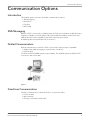
Introduction
This chapter gives a overview of possible communication options:
• SMS messaging
• Dialled line
• Fixed line
• MTC-COM
SMS Messaging
When the FGC is connected to a GSM modem, the FGC can send alarms as SMS directly to
telephones capable of receiving them. Up to three different numbers can be listed. Any
SMS will be sent to these numbers in the same order as they are listed.
A SCADA system can still dial the FGC to monitor it.
Dialled Communication
Dialled communication is when the FGC is connected to either a Hayes compatible:
• GSM modem (SMS messaging is a special case, see above)
• PSTN modem
The FGC can dial a SCADA system to report alarms. The SCADA system can dial the FGC
to monitor it and collect data.
Figure 1
Fixed Line Communication
Fixed line communication is when the FGC is connected to either:
• Fix line modem
• Radio modem
• Directly to a PC with a serial cable
FGC Communication Module Installation Manual
5
Communication Options
The FGC and a SCADA system can communicate with each other over the fixed line. There
are two options:
• Full duplex (FDX) is used for radio modems, serial cables, and 4-wire fix line modems.
• Half duplex (HDX) is used for 2-wire fix line modems.
Figure 2
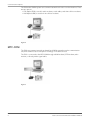
MTC-COM
The FGC can communicate with an AquaView SCADA system through a communication
unit, MTC-COM. It acts as a telephone exchange or modem selector.
The FGC is connected to the MTC-COM through a GSM modem, PSTN modem, radio
modem, or directly with a signal cable.
Figure 3
6
FGC Communication Module Installation Manual
Installation
Installation
Introduction
The FGC communication module enables communication with a SCADA system, for
example AquaView.
The module is mounted inside the FGC (Flygt General pump Controller).
Installing the Module
How to install the communication module on the FGC main board is described below.
Mounting the Module
1.
2.
3.
4.
Turn off mains power for the FGC.
Unscrew the four screws that holds the front lid of the FGC.
Remove the front lid.
If installed, remove the battery backup module.
FGC Communication Module Installation Manual
7
Installation
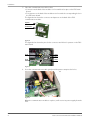
5. Place the communication module so that:
• Connector at the back of the module is in line with the four pins on the FGC main
board.
• Four spacers on the back of the module are in line with the corresponding holes in
the FGC main board.
The figure below shows the connector and spacers on the back of the FGC
communication module.
Spacer
Connector
Figure 4
The figure below shows the pins for the connector and holes for spacers on the FGC
main board.
Hole
Hole
Pins
Hole
Hole
Figure 5
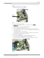
6. Press the communication module gently until the spacers snap into the holes.
Figure 6
When the communication module is in place, it will receive its power supply from the
FGC.
8
FGC Communication Module Installation Manual
Installation
Connecting the Module
1. Connect the module either to a modem or directly to a PC/MTC-COM with a signal
cable.
• Modem: Continue with List item. (page 9)
• PC/MTC-COM: Skip to List item. (page 9)
RS232
Connector
Figure 7
2. To connect the module to a modem:
1. Read about compatible modems in the separate document Modem
Configuration.
2. Make sure there is no power supply for the modem.
3. Connect a straight serial cable to the modem.
4. Connect the cable to the RS232 connector on the communication module.
5. To power the modem, you can use the internal supply from the FGC main board
or an external source.
Connect the modem to its power supply.
(For information on how to connect to the power supply from the FGC main
board, refer to the FGC Installation manual.)
6. Skip to List item. (page 10).
3. To connect the module directly to a PC/MTC-COM with a signal cable:
1. Connect a serial null-modem cable to the PC/MTC-COM.
2. Connect the cable to the RS232 connector on the communication module.
Figure 8
FGC Communication Module Installation Manual
9
Installation
Checking the Module
1. If previously removed, mount the battery backup module in the FGC.
2. Turn on mains power for the FGC.
3. If you use a modem connected to an external power supply, turn on that power
supply.
4. If you use a modem, turn it on.
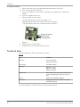
5. Check the LEDs on the module:
• Power LED indicates if the power supply is ok.
• RX LED indicates when the module receivers information
• TX LED indicates when the module transmits information.
Power LED (green)
RX LED (red)
TX LED (green)
Figure 9
6. Fasten the front lid of the FGC.
7. Fasten the four screws that holds the front lid.
Technical data
Technical data for the FGC communication module:
Table 2
Size
85x64mm.
Connection
Socket to main board.
Cable for external device.
Power supply
From FGC main board.
Indications
LED for RX = receive
LED for TX = transmit
LED for power supply
Real time clock
Date and time (hours, minutes and seconds). The clock
has its own battery backup that lasts for more than 5
years.
Protocol
AquaCom, Comli, Modbus, or SMS text.
User interface
Configured through the FGC or FGC-term (a separate,
hand-held display-unit).
For technical data on the FGC, refer to its Technical specification.
10
FGC Communication Module Installation Manual
Communication Configuration
Communication Configuration
Introduction
This chapter describes communication configuration. For information on available options,
see also Communication Options (page 5).
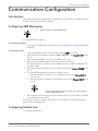
Configuring SMS Messaging
SMS messaging only works with GSM modems.
To configure SMS messaging:
Configuring the Modem
1. Configure the GSM modem using a PC, see also Appendix A: Configuring a Modem
(page 24).
Configuring the FGC
1. Select "GSM/Hayes predef." in the Communication COM1 menu (18_).
2. Enter the speed used with the modem (2400-57600 bps) in the Speed COM1 menu
(18_1).
3. Select "AquaCom/SMS" in the Protocol COM1 menu (18_2).
4. Enter the current date and time in the Date and Time menu (12_).
This date and time is included in any sent SMS, but also used when sampling trend
and report data.
5. Enter the telephone number to the (first) SMS receiver in the Tele no. CS/SMS menu
(12_1).
6. To use alarm handling with more than one SMS receiver:
1. Enter the telephone number to a second SMS receiver in the Tele no. SMS 2
menu (12_2).
2. Enter the telephone number to a third SMS receiver in the Tele no. SMS 3 menu
(12_3).
If a space (empty field) in entered as the first part of a telephone number, it
will be excluded as SMS receiver.
7. Enter a name for the station in the Station name menu (12_6). This name is included
in any SMS sent from the FGC.
If desired, you can also configure alarm options as described in Configuration Options Alarms Sent as SMS (page 14).
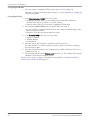
Configuring Dialled Line
To configure a dialled line:
FGC Communication Module Installation Manual
11
Communication Configuration
Configuring the Modem
1. If you use a Hayes compatible PSTN modem, skip to List item. (page 12).
Otherwise, configure the GSM modem using a PC, see also Appendix A: Configuring
a Modem (page 24).
Configuring the FGC
1. In the Communication COM1 menu (18_), select:
• "GSM/Hayes predef." when you use a GSM modem. (If an MTC-COM unit is
included in the system, you have to select this option).
• "Hayes modem" when you use a Hayes compatible PSTN modem.
2. Enter a speed (2400-57600 bps) in the Speed COM1 menu (18_1).
• If you use a Hayes compatible PSTN modem, and it supports autobauding, set the
speed as high as possible.
• Otherwise, enter the speed used with the modem.
3. In the Protocol COM1 menu (18_2), select either:
• "AquaCom dialled"
• "Modbus dialled"
• "Comli dialled".
4. Enter the current date and time in the Date and Time menu (12_).
This date and time is included as alarm information, but also used when sampling
trend and report data.
5. Enter the telephone number to the SCADA system or MTC-COM unit in the Tele no.
CS/SMS menu (12_1).
6. Enter a number (0–899) in the Station no./id menu (12_7). This number must uniquely
identify the FGC within the SCADA system.
If desired, you can also configure alarm options as described in Configuration Options Alarms Sent to SCADA System (page 15).
12
FGC Communication Module Installation Manual
Communication Configuration
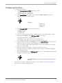
Configuring Fixed Line
To configure a fixed line:
1. In the Communication COM1 menu (18_), select:
• "RS232 FDX" to use Full Duplex
• "RS232 HDX" to use Half Duplex
2. In the Speed COM1 menu (18_1), set the speed (2400-57600 bps) to the port
baudrate used in the SCADA system.
The FGC uses:
• Data bits = 8
• Parity = None
• Stop bits = 1
3. In the Protocol COM1 menu (18_2), select either:
• "AquaCom fixed"
• "Modbus fixed"
• "Comli fixed"
4. If you use a fix line modem and the communication is set to "RS232 HDX", enter a
time delay (25-1000 ms) in the RTS delay COM1 menu (18_3).
Low delay means faster communication:
• Generally, use the same value as in the SCADA system.
• Try a higher value if there are problems with the communication.
5. Enter a maximum buffer size (80-4000 bytes) in the Max buffer size menu (18_4). The
buffer size limits the amount of trend data that can be sent at a time.
If you use a radio modem with a limited buffer or there are disturbances, try a lower
value, for example 200.
6. Enter the current date and time in the Date and Time menu (12_).
This date and time is included as alarm information, but also used when sampling
trend and report data.
7. Enter a number (0–899) in the Station no./id menu (12_7). This number must uniquely
identify the FGC within the SCADA system.
In an Aquaview SCADA system, the station number and fixed line id must be the
same value.
If desired, you can also configure alarm options as described in Configuration Options Alarms Sent to SCADA System (page 15).
FGC Communication Module Installation Manual
13
Alarm Configuration
Alarm Configuration
Introduction
This chapter describes alarm configuration. It is generally different depending on whether
the FGC sends out the alarms as SMS or sends them to a SCADA system.
Configuration Options - Alarms Sent as SMS
Alarm Priority
When sending out alarms as SMS, the alarm priority determines what happens with the
alarm.
A Alarm is sent to SMS receivers.
B Alarm is sent to SMS receivers.
C Alarm is not sent out. It is only local in the FGC.
D Alarm is sent to SMS receivers according to the D-alarm time frame in the FGC.
To change the alarm priority for an alarm:
1. If necessary, select "Yes" in the Parameter menu (6).
2. Select the alarm in the Alarm prio.index menu (11_4).
3. Select an alarm priority in the Alarm priority menu (11_5).
D-alarm Time Frame
D-alarms are sent out as SMS only between the specified D-alarm start time and D-alarm
end time. If the alarm occurs at any other time, the FGC will wait until the D-alarm time
frame begins and then send the alarm.
Example: Alarms are sent out between 08:00 and 16:30.
To specify the start and end time:
1. If necessary, select "Yes" in the Parameter menu (6).
2. Enter the start time in the D-Alr.start time menu (11_7).
3. Enter the end time in the D-alarm end time menu (11_8).
To inhibit the function, enter 0 in both D-Alr.start time and D-alarm end time menus. Any
D-alarm will be treated as an A alarm.
Acknowledgement
When the FGC sends an alarm as SMS, the FGC waits a specified time for an alarm
acknowledgment. This time is called "alarm acknowledgement time".
If no alarm acknowledgement is received within the acknowledgement time, the FGC will
send the alarm to cell phone number 2 in the list.
If there still is no acknowledgment, the FGC will send the alarm to cell phone number 3 in
the list.
If all numbers have been dialled, but no alarm acknowledgement has been received, the
specific alarm will not be sent again.
If the alarm acknowledgement is received within specified time, the alarm will not be sent
out to the following cell phone numbers.
To specify alarm acknowledgement:
1. If necessary, select "Yes" in the Parameter menu (6).
2. In the SMS Ack. time menu (12_4), enter either:
• Alarm acknowledgement time (minutes)
• "0" to disable the acknowledge request.
14
FGC Communication Module Installation Manual
Alarm Configuration
If the acknowledge time is set to 0, the FGC will not wait for any acknowledgement.
Instead, the alarm is sent out directly as SMS to all listed cell phone numbers.
Passive Alarms
SMS can be sent out when an alarm becomes passive. Such an alarm is called a "P-alarm".
To specify what to do with P-alarms:
1. If necessary, select "Yes" in the Parameter menu (6).
2. In the SMS P-alarm menu (12_5), select either:
• "No" to not send out SMS when an alarm becomes passive.
• "Yes" to send out SMS when an alarm becomes passive.
Configuration Options - Alarms Sent to SCADA System
Alarm Priority
When communicating with a SCADA system, the alarm priority determines what happens
with the alarm.
A Alarm is sent to the SCADA system.
B Alarm is sent to the SCADA system.
C Alarm is not sent out. It is only local in the FGC.
D Alarm is sent to the SCADA system according to the D-alarm time frame in the SCADA
system.
To change the alarm priority for an alarm:
1. If necessary, select "Yes" in the Parameter menu (6).
2. Select the alarm in the Alarm prio.index menu (11_4).
3. Select an alarm priority in the Alarm priority menu (11_5).
Alarm Code Filter
Each possible alarm in the FGC has a corresponding alarm code.
When an alarm is sent from the FGC to the SCADA system, the alarm message contains the
alarm code for the alarm.
The SCADA system then uses the alarm text that corresponds to the alarm code.
When you change the alarm code for the external alarm in the FGC, the SCADA system will
instead use the alarm text associated with the new alarm code.
To change the alarm code for the external alarm:
1. If necessary, select "Yes" in the Parameter menu (6).
2. Enter the new code in the Code gen. input menu (11_6).
Alarm codes are normally changed from the SCADA system. The corresponding alarm
texts can also be set in the SCADA system.
FGC Communication Module Installation Manual
15
Alarm Operation
Alarm Operation
Introduction
Depending on the configuration, the FGC sends a new alarm either to the SCADA system
or directly to cell phones as SMS.
When sent to a SCADA system, the sending can fail, for example if the SCADA system is
busy. If the sending fails, the FGC will wait for 1 minute before the next attempt. Following
each successive failure, the waiting time is increased by 1 minute until 10 successive
attempts have failed. The FGC will then wait for 3 hours before the dialling sequence is
recommenced.
How the FGC acts when an alarm is sent out as SMS is described in Configuration Options Alarms Sent as SMS (page 14).
Disabling Alarms Temporarily
When working in a pump station, you can temporarily stop any alarms from being sent out,
for example to avoid false alarms when cleaning the pump sump.
When the work is finished, you have two options:
• Allow new alarms to be sent out. Any buffered alarm will be sent out as well.
• Clear the alarm buffer from any alarm. When cleared, new alarms will be allowed to be
sent out.
To temporarily stop any alarm from being sent out:
1. If necessary, select "Yes" in the Parameter menu (6).
2. Select "Local" in the Transmit Alarm menu (11_3).
To allow alarms to be sent out:
1. If necessary, select "Yes" in the Parameter menu (6).
2. In the Transmit Alarm menu (11_3), select either:
• "Clear" to clear the alarm buffer before allowing new alarms to be sent out.
• "Remote" to allow both buffered and new alarms to be sent out.
Receiving Alarms Sent as SMS
An example of an alarm sent as SMS is shown below:
1 - Kristianstadvägen 2004-06-17
21:45 A High level (A)
The information given in the SMS is:
• Station number. In this example 1.
• Station name. In this example Kristianstadvägen.
• Date and time. In this example 2004-06-17 21:45.
• Alarm priority. In this example A.
• Alarm text. In this example High level.
• Active (A) or passive (P) alarm. In this example (A).
Acknowledge Alarms Sent as SMS
To acknowledge an alarm received as SMS, you can either:
• Call the FGC.
• Reply to the SMS (no text is required).
16
FGC Communication Module Installation Manual
Flygt SCADA System (AquaView)
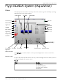
Flygt SCADA System (AquaView)
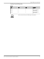
Status
The status picture shows the momentary status of the station together with daily operating
data along with a list of active alarms.
Relay status
P1 status
Other status
Active alarms
RTU info
Power failure
Level
High level
Max level
Tripped
High level
Max runtime
Start level
Stop level
High temp.
Response err.
Overflow
Alarm handling
(local/remote)
P1 run time
P1 starts
P1 current
Alternation
Overflow time
Overflow count
Figure 10
RTU Information
Click RTU info to show information on the system and application versions used in the
FGC.
Remote Control
As part of the status the FGC can be remotely controlled. Right-click in the status picture to
display a dialog box for remote control.
Table 3
Object
Description
P1
F1 = Start pump 1
F2 = Stop and block pumps
F3 = Return control to automatic
F4 = Reset unit
FGC Communication Module Installation Manual
17
Flygt SCADA System (AquaView)
Object
Description
P2
F1 = Start pump 2
F2 = Stop and block pumps
F3 = Return control to automatic
F4 = Reset unit
The FGC reverts to the automatic mode within 30 seconds after the modem has hung up.
Set Points
Set Point Values
Set point values can be fetched and sent in random order. Maximum is 250 transmitted
characters.
Alarm Code Filter
Alarm code filter can be fetched and sent in random order.
Fetching alarm code filter requires at least AquaView 1.23.01.
Alarm Priority
Alarm priorities can be fetched and sent in random order.
Fetching alarm priorities requires at least AquaView 1.23.01.
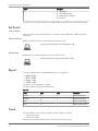
Report
The report data consists of daily data divided into 4 segments.
• 00:00 - 06:00
• 00:06 - 09:00
• 09:00 - 16:00
• 16:00 - 24:00
The FGC stores report data for 3 days.
The report data is listed in the table below.
Table 4
Text1
Text2
Text3
Description
Run time
P1
h
Running time Pump 1.
Run time
P2
h
Running time Pump 2.
Starts
P1
Number of starts pump 1.
Starts
P2
Number of starts pump 2.
Trend
The trend data consist of historical data. Possible sample resolution:
• 1-minute average
• 5-minute average
Enter the preferred resolution in the Trend resolution menu (12_8).
18
FGC Communication Module Installation Manual
Flygt SCADA System (AquaView)
The FGC stores trend data for 3 days.
Trend data is listed in the table below.
Table 5
Text1
Text2
Level
Text3
Description
m
Level
Current
P1
A
P1 current. (Maximum
value in period)
Current
P2
A
P2 current. (Maximum
value in period)
Select the same trend resolution in the FGC settings as in the AquaView.
FGC Communication Module Installation Manual
19
Other SCADA Systems
Other SCADA Systems
Introduction
The FGC supports several communication methods for communicating with other SCADA
systems. Below is a list of available connection types and protocols.
Table 6
Protocol:
Connection Type:
Aquacom
Fixed
Aquacom
Dialled
Aquacom
Dialled + SMS Alarms
Comli
Fixed
Comli
Dialled
Modbus
Fixed
Modbus
Dialled
Note: See the Open manual for further information on protocols.
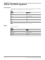
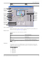
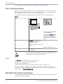
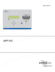
Status
The status view shows:
Table 7
20
Category:
Example:
Status
Pump status
Operating data
Run time (daily value)
Active alarms
High level
Parameters
Level range
FGC Communication Module Installation Manual
Other SCADA Systems
Category:
Example:
Remote Control
Start/Stop P1
Alarm list
Modem
Connection
Level
Pump status
Relay status
Level range
High level
Start level 2
Start level 1
Stop level 2
Stop level 1
Power fail
High level
Tripped
Max run time
High temp
Response error
Run time daily
Starts daily
Current
Figure 11: Example using Citect
Additional parameters, alarms, and values supported by the FGC can be added to the
status view, see also Appendix B: Tag List (page 25).
Remote Control
The following functions can be remotely controlled:
Table 8
Start P1
Start Pump 1/Stop Pump 1
Start P2
Start Pump 2/Stop Pump 2
Block
Block all pumps
Reset
Reset motor protection
Resume to auto
Functions will no longer be controlled remotely
Note: If the communication to the FGC is lost, the pump will return to automatic mode
after 30 seconds.
Parameters
The parameters shown in the SCADA status view can be altered by the operator and
changes the conditions under which the FGC operates. See list below for examples of
parameters that can be altered.
Example of parameters:
1. Level Range
2. High Level
3. Start Level 2
4. Start Level 1
5. Stop Level 2
6. Stop Level 1
FGC Communication Module Installation Manual
21
Other SCADA Systems
For a complete parameter list, see also Appendix B: Tag List (page 25).
Alarm Handling (Dialup)
When an alarm is triggered in the FGC, it will call the SCADA system in order to be polled
by the SCADA system for the alarm list. For the SCADA system to recognize which FGC
that is making the call, a caller id is sent to the SCADA system.
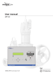
The table below shows an outgoing alarm call from the FGC to the SCADA system.
Table 9
Phase
Scada system
Esc
Au t a m a t ic Pu m p Pilo t
OK
APP 5 4 1
1
-
The alarm is triggered and the FGC
calls the SCADA system
2
-
The FGC sends its caller id, see also
Alarm Handling (Dialup) (page 22).
The caller id field in the SCADA
system must correspond to the sent
caller id.
3
If caller id is not supported by the
SCADA system it will request a
PLC_ID from the FGC.
-
4
The SCADA system shall poll for active alarms.
5
-
The FGC acknowledges the alarm.
6
The SCADA system shall terminate
the connection
-
To prevent the FGC from sending alarms not included in the SCADA system, change
the alarm priority to "C" for relevant alarms in the FGC.
Caller Id
The caller id is automatically generated by the FGC.
Syntax: FLYGT_<protocol>_<station number>
Example: FLYGT_MODBUS_31
In previous example, the protocol is Modbus and the station number is 31.
If the station number is changed in the FGC, the caller id will change accordingly. For
example, if the station number is changed from 31 to 32 in the FGC, the FGC will generate
another caller id: FLYGT_MODBUS_32.
Max Buffer Size (Advanced Settings)
The information provided below is intended for integration purposes and should be used
together with the Open manual.
22
FGC Communication Module Installation Manual
Other SCADA Systems
The SCADA system must not exceed the Max buffer size in the FGC when requesting
registers or other data.
Table 10
Protocol
Max No. of registers in one reply
Max No. of digital I/O in one reply.
Modbus
57
920
Comli1
32
512
Note: The max reply Buffer Size is 120 bytes.
When a GSM modem is used, GSM-network delays may cause the SCADA system to
timeout. To solve this, either:
• Increase the timeout setting in the SCADA system.
• Decrease the number of registers/IO in each request.
1
The limitation is in Comli, where the data bytes are limited to 64.
FGC Communication Module Installation Manual
23
Appendix A: Configuring a Modem
Appendix A: Configuring a Modem
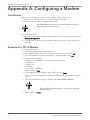
Introduction
When you use a modem, you may need to configure it. If you want to use:
• Default factory settings, there is no need to configure the modem.
• Other settings, you need to configure the modem.
With an MTC-COM unit in the system, you also need to configure the modem. The
factory settings cannot be used in this case.
To configure a modem:
1. Read about compatible modems and initialization strings in the separate document
Modem Configuration.
2. Configure the modem using the relevant initialization strings, see also below for an
example.
Example of a TD-33 Modem
To configure the modem:
1. Start the program Windows Hyperterminal.
2. In the displayed dialog box, enter a name for the connection, and click OK.
3. Select the COM-port used for the modem, for example, COM1. Click OK.
4. Configure the COM-port:
• Bits per second: 9600 (or another speed you want to use)
• Data bits: 8
• Parity: none
• Stop bits: 1
• Flow control: Hardware
When ready, click OK.
5. In the displayed terminal window, type "AT&F" and click Enter.
This will load the factory default configuration. When ready, the modem will answer
"OK".
6. Type in the initialisation string, for example: AT&FE0V1\N0W2 S0=0&W.
"&W" is part of listed initialization strings. As a result, a string is permanently
stored in the modem.
7. When ready, click Enter.
24
FGC Communication Module Installation Manual
Object nam e
ALR_DigitalAlarmDela y
ALR_Mod e
LEV1_HighAlarmLimi t
LEV1_Percen t
LEV1_Rang e
LEV1_Valu e
OF1_ActiveCountTota l
OF1_ActiveTimeTota l
P1_Current
P1_HighCurren t
P1_RunTimeDaily
P1_StartCountDail y
P1_StartLeve l
P1_StopLeve l
P2_Current
P2_HighCurren t
P2_RunTimeDaily
P2_StartCountDail y
P2_StartLeve l
P2_StopLeve l
PF_AlarmDela y
S1_AllowedPumpToRu n
S1_AlternationTyp e
S1_DigitalRunTime
S1_HourRunInterva l
S1_HourRunTim e
S1_MaxRunTim e
S1_MinRunFloatHig h
S1_StopDelay
Addr
207
208
98
2
92
1
58
56
6
121
34
36
111
112
8
141
38
FGC Communication Module Installation Manual
40
131
132
217
192
50
197
200
201
202
204
196
INT
INT
INT
INT
0
0
0
0
0
-9999
-9999
0
0
0
0
1
UNSIGNED INT
SIGNED INT
SIGNED INT
UNSIGNED INT
UNSIGNED INT
UNSIGNED INT
UNSIGNED INT
UNSIGNED INT
UNSIGNED
UNSIGNED
UNSIGNED
UNSIGNED
0
-9999
-9999
0
0
0
-9999
0
0
-9999
0
0
0
0
0
SIGNED INT
UNSIGNED INT
UNSIGNED INT
SIGNED INT
UNSIGNED INT
UNSIGNED INT
UNSIGNED INT
UNSIGNED INT
UNSIGNED INT
UNSIGNED INT
SIGNED INT
SIGNED INT
UNSIGNED INT
UNSIGNED INT
UNSIGNED INT
0
0
Raw
min
UNSIGNED INT
UNSIGNED INT
Typ e
120
3000
3000
600
SI
SI
SI
SI
SI
SI
SI
SI
SI
SI
SI
SI
SI
SI
SI
SI
SI
SI
65535
9999
9999
9999
9999
65535
65535
9999
9999
600
10
3
600
200
SI
SI
SI
SI
SI
SI
SI
SI
SI
Unit
syste m
SI
SI
9999
100
9999
9999
65535
65535
9999
9999
65535
600
2
Raw
max
1
1
1
1
1
0,01
0,01
1
1
1
1
3600
1
0,01
0,01
0,1
0,1
60
0,01
1
0,01
0,01
1
60
0,1
0,1
60
Multipl y
by…
1
1
Scal e
s
s
s
s
s
s
m
m
s
m
m
A
A
s
s
A
A
s
m
m
m
…to get
uni t
s
RW
RW
RW
RW
R
RW
RW
RW
RW
RW
RW
RW
R
RW
RW
R
RW
R
RW
R
RW
R
R
R
R
RW
R
RW
RW
RW
Alarm delay.
Alarm distribution mode: 0 = local, 1 = remote
and 2 = clear.
High level alarm limit.
Level in percent.
Measure range for the level sensor.
Level in meters.
To tal number of overflows.
Total time in minutes of overflowing .
Current pump 1.
High current alarm limit pump 1.
Run time in minutes of pump 1 in the present
day.
Number of starts on pump 1 in the present day.
Start condition 1.
Stop condition 1.
Current pump 2.
High current alarm limit pump 2.
Run time in minutes of pump 2 in the present
day.
Number of starts on pump 2 in the present day.
Start condition 2.
Stop condition 2.
Power failure alarm delay.
Number of allowed pump to run.
Alternation type.
Digital run time.
Forced pump start '96'-hour, interval 1 - 200
hours .
Forced pump start '96'-hour, run time.
Max Run time, Max: 50 min ( 30000).
High level float minimum run time sump.
Stop delay .
Descriptio n
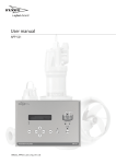
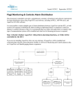
Appendix B: Tag List
Appendix B: Tag List
Appendix B: Tag List
Figure 12
25
26
Object nam e
SYS_AppVerAq v
SYS_Languag e
SYS_PlantNo
SYS_Versio n
D01_Alar m
LEV1_DigHighAlar m
LEV1_HighAlar m
LEV1_SensorAlar m
OF1_Alar m
P1_Blocked
P1_Error
P1_ErrorResponseAlar m
P1_MaxRunAlar m
P1_RemoteRu n
P1_Respons e
P1_Run
P1_ThermAlar m
P1_TripAlar m
P2_Blocked
P2_Error
P2_ErrorResponseAlar m
P2_MaxRunAlar m
P2_RemoteRu n
P2_Respons e
P2_Run
P2_ThermAlar m
P2_TripAlar m
PALR_PersonnelAlar m
PF_Alar m
S1_AutoResetEnabl e
S1_RemoteBloc k
S1_RemoteRese t
S1_RevertToAut o
SYS_ParamErrorAlar m
Addr
226
225
584
295
101
5
2
10
99
15
14
22
26
18
13
12
23
19
31
30
38
42
34
29
28
39
35
87
88
79
77
78
200
97
UNSIGNED
UNSIGNED
UNSIGNED
UNSIGNED
DIGITAL
DIGITAL
DIGITAL
DIGITAL
DIGITAL
DIGITAL
DIGITAL
DIGITAL
DIGITAL
DIGITAL
DIGITAL
DIGITAL
DIGITAL
DIGITAL
DIGITAL
DIGITAL
DIGITAL
DIGITAL
DIGITAL
DIGITAL
DIGITAL
DIGITAL
DIGITAL
DIGITAL
DIGITAL
DIGITAL
DIGITAL
DIGITAL
DIGITAL
DIGITAL
Typ e
INT
INT
INT
INT
0
0
0
0
0
0
0
0
0
0
0
0
0
0
0
0
0
0
0
0
0
0
0
0
0
0
0
0
0
0
0
0
0
0
Raw
min
65535
12
65535
65535
1
1
1
1
1
1
1
1
1
1
1
1
1
1
1
1
1
1
1
1
1
1
1
1
1
1
1
1
1
1
Raw
max
Unit
syste m
SI
SI
SI
SI
Multipl y
by…
1
1
1
1
Scal e
…to get
uni t
R
RW
R
R
R
R
R
R
R
R
R
R
R
RW
R
R
R
R
R
R
R
R
RW
R
R
R
R
R
R
RW
RW
RW
RW
R
RW
Version of the AquaView application .
Chosen language.
Plant identifier number
System version .
Alarm on digital input 1 is active.
Digital high level sensor alarm after delay.
High level alarm is active.
Sensor failure alarm.
Overflow alarm is active.
Pump 1 is blocked.
Pump 1 has an error.
No responce alarm is active on pump 1.
Max run alarm is active on pump 1.
Manual or remote start of pump 1.
Responce from pump 1.
Pump 1 is running.
High temperature alarm is active on pump 1.
Tripped alarm on pump 1.
Pump 2 is blocked.
Pump 2 has an error.
No responce alarm is active on pump 2.
Max run alarm is active on pump 2.
Manual or remote start of pump 2.
Responce from pump 2.
Pump 2 is running.
High temperature alarm is active on pump 2.
Tripped alarm on pump 2.
Personnel alarm.
Power failure alarm is active.
Over current auto reset function enable.
P1/P2 Remote block pump.
Remote reset (resets alarms and pump errors).
Revert to automatic control of the pumps.
Parameter error alarm.
Descriptio n
Appendix B: Tag List
Figure 13
FGC Communication Module Installation Manual
Appendix C: FGC Versions
Appendix C: FGC Versions
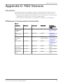
Introduction
This manual describes the configuration when the communication module is used in an
FGC 313/323. If the communication module is used in an FGC series I or FGC Series II:
• Menu names and indications may be different. For more information on menus names
and indications in FGC Series I or II, refer to its User manual.
• All communication functionality is not available. The differences are listed below.
Differences in Communication Functionality
Table 11
Functionality
FGC series I
FGC series II
FGC 313/323
Functionality
described for FGC
313/323
Telephone numbers
for SCADA system
and SMS
1
1
3
Communication
Configuration (page
11)
Alarm
acknowledgement
time
Not available
Not available
Available
Configuration
Options - Alarms Sent
as SMS (page 14)
Sending SMS when
alarms become
passive
Always sent
Always sent
Sending can be
enabled or disabled
Configuration
Options - Alarms Sent
as SMS (page 14)
Alarm code filter
Not available
Not available
Available
Configuration
Options - Alarms Sent
to SCADA System
(page 15)
Service alarm Pump
1 ("Service P1")
Not available
Not available
Available
Alarm list in FGC User
manual
Service alarm Pump
2 ("Service P2")
Not available
Not available
Available
Alarm list in FGC User
manual
Test alarm ("Test
call!")
Not available
Not available
Available
Alarm list in FGC User
manual
FGC Communication Module Installation Manual
27
Xylem |’zīləm|
1) The tissue in plants that brings water upward from the roots
2) A leading global water technology company
We're 12,000 people unified in a common purpose: creating
innovative solutions to meet our world's water needs. Developing new
technologies that will improve the way water is used, conserved, and
re-used in the future is central to our work. We move, treat, analyze,
and return water to the environment, and we help people use water
efficiently, in their homes, buildings, factories and farms. In more than
150 countries, we have strong, long-standing relationships with
customers who know us for our powerful combination of leading
product brands and applications expertise, backed by a legacy of
innovation.
For more information on how Xylem can help you, go to xyleminc.com
Xylem Water Solutions AB
Gesällvägen 33
174 87 Sundbyberg
Sweden
Tel. +46-8-475 60 00
Fax +46-8-475 69 00
http://tpi.xyleminc.com
Visit our Web site for the latest version of this document and
more information
The original instruction is in English. All non-English
instructions are translations of the original instruction.
©
2011 Xylem Inc
896766_2.1_en.GB_2012-01_IOM_FGC_COM_MOD