1
PowerNut
User’s Manual
PowerNut User’s Manual
JK microsystems
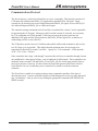
Unless otherwise noted, this document and the information herein disclosed are proprietary to JK
microsystems, Inc. Any person or entity to whom this document is furnished or having
possession thereof, by acceptance, assumes custody thereof and agrees that the document is given
in confidence and will not be copied or reproduced in whole or in part to meet the purposes for
which it was delivered.
The information in this document is subject to change without notice, and should not be
construed as a commitment by JK microsystems, Inc. JK microsystems, Inc. will make every
effort to inform users of substantive errors.
JK microsystems, Inc. disclaims all liability for any loss or damage resulting from the use of this
manual or any software described herein, including without limitation contingent, special, or
incidental liability.
JK microsystems, Inc. recognizes our customer’s need for a consistent product and will make
every effort to provide one. In order to provide the best possible product for all of our customers,
we reserve the right to make incremental improvements in our product designs.
Flashlite is a trademark of JK microsystems, Inc. MS-DOS is a registered trademark of Microsoft
Corporation. XDOS is a copyright of HBS Corporation. All other brand and product names are
trademarks or registered trademarks of their respective companies.
PowerNut User’s Manual Version 1.0
Copyright © JK microsystems, Inc.
All rights reserved
Printed in U.S.A.
Document Part No. 94-0025
Published April 2003
i
JK microsystems
PowerNut User’s Manual
Limited Warranty
JK microsystems, Inc. warrants each PowerNut to be free from defects in material and workmanship
for a period of 90 days from the date of purchase. This warranty shall not apply to any unit which has
been subject to misuse, neglect, accident, or abnormal conditions of operation.
JK microsystems’ obligation under this warranty is limited to repairing or replacing, at JK
microsystems’ option, any unit returned to the factory within 90 days of the date of purchase,
provided that JK microsystems determines that the unit is defective and has been used in
compliance with the terms of this warranty. If the failure has been caused by misuse, neglect,
accident, or abnormal conditions of operation, repairs will be billed at a nominal cost.
The foregoing warranty is exclusive and in lieu of all other warranties, expressed or implied,
including, but not limited to, any warranty of merchantability or fitness for any particular
purpose. JK microsystems shall not be liable for any special, incidental or consequential
damages, whether in contract, tort, or otherwise.
Important Notice
Life Support / Mission Critical Applications
This product is not fault-tolerant and is not designed, manufactured or intended for use or resale
as on-line control equipment in hazardous environments requiring fail-safe performance, such as
in the operation of nuclear facilities, aircraft navigation or communication systems, air traffic
control, direct life support machines, or weapons systems, in which the failure of our hardware or
software could lead directly to death, personal injury, or severe physical or environmental
damage.
ii
Limited Warranty
PowerNut User’s Manual
JK microsystems
Table of Contents
Limited Warranty ............................................................................................................................... i
Table of Contents ............................................................................................................................. iii
Overview ......................................................................................................................................... 1
Features ........................................................................................................................................... 1
Operation ......................................................................................................................................... 2
Getting Started ................................................................................................................................. 2
Getting Oriented ......................................................................................................................... 3
Turning on the PowerNut ............................................................................................................ 5
Controlling the PowerNut ........................................................................................................... 6
Powering a Downstream Controller ............................................................................................. 8
Periodically Running an Application ............................................................................................. 9
Hardware ....................................................................................................................................... 10
General Theory of Operation .................................................................................................... 10
Jumpers and Connectors ........................................................................................................... 15
Communications Protocol ............................................................................................................... 17
Commands and Capabilities ............................................................................................................ 22
Shutdown ................................................................................................................................. 22
Set configuration word .............................................................................................................. 22
Perform Low-Battery Test ........................................................................................................ 24
Guidelines for Reliability .................................................................................................................. 25
Software ........................................................................................................................................ 26
NUTCOMM ........................................................................................................................... 26
WAK10SEC ............................................................................................................................ 27
CNUT ..................................................................................................................................... 27
Specifications ................................................................................................................................. 28
Mechanical Drawing ....................................................................................................................... 28
Contact Information ........................................................................................................................ 29
Table of Contents
iii
JK microsystems
iv
PowerNut User’s Manual
JK microsystems
PowerNut User’s Manual
Overview
The PowerNut gives system developers a clean tool to manage power in battery powered
applications. The PowerNut takes power from the battery and supplies voltage (regulated or raw
battery voltage) to downstream devices. The primary system controller sends commands to the
PowerNut indicating if power should be shutdown to downstream devices, and for how long.
Typically the primary system controller will be downstream of the PowerNut and will therefore
have the ability to shut itself off for a period of time. However, the PowerNut can also be used
as a “smart” solid-state relay to control power to subsystems that do not contain the primary
system controller.
The PowerNut allows any controller or datalogger to gain efficient and reliable control over the
system’s power supply. Many controllers and dataloggers can not shut themselves off or to wake
up after time has elapsed.
The PowerNut uses an ultra-low quiescent current regulator and a low-power PIC processor
running at 32768 Hz to supervise downstream power. The PIC processor has a built-in analog to
digital converter that can be used for low battery detection. Because the PIC never sleeps, the
clocked serial port can be used to wake up downstream devices.
The PowerNut is a reliable and versatile tool that provides complete control over your system’s
power.
Features
Input voltage 5-30 volts (if using the on-board 5 volt regulator, then 7-30 volts)
Capable of switching 1 amp
On-board 5 volt 1-amp high-efficiency switching regulator
Downstream power can be “regulated 5 volts” or “raw input voltage”
On-board programmable low voltage detection and reporting
Simple to use clocked serial interface
On-board “heartbeat” LED with programmable enable
Easy to use screw-terminals for input and downstream power
Compact 2” x 3” footprint
On-board programmable timer allows automatic wake-up of downstream devices
Use of parity and ACK/NACK ensures reliable message exchange
PowerNut consumes 180µA max (58-100µA typical) when downstream devices are off
Overview
1
JK microsystems
PowerNut User’s Manual
Operation
When power is first applied to the PowerNut’s power-in connector (J1), the PowerNut energizes
the downstream connector (J2). This will supply power to downstream devices.
The downstream voltage may be selected to be 5 volts, generated by the PowerNut’s on-board 5
volt regulator, or to be approximately equivalent to the “raw input voltage.”
!
Warning! If you plan to use the PowerNut to supply voltage to a device that
requires a regulated 5 volt supply, then you must set the jumpers on JP3 before
applying power. If the jumpers on JP3 are configured incorrectly then the
downstream device will be provided with a voltage higher than five volts. This
WILL CAUSE DAMAGE to a 5 volt only device.
Commands are sent to the PowerNut over the clocked serial port. The PowerNut ignores
commands sent within one second of a PIC reset (such as occurs when input power is first
applied to J1). The PowerNut also ignores commands sent within one second of turning off or on
the downstream voltage. This ensures the power is stable on downstream devices before
commands are accepted by the PowerNut. This is a technique that rejects the noise that occurs
on the clocked serial interface when a downstream device is making a power transition and
attempting to drive the serial interface.
If a command is sent while the PowerNut is not accepting commands, the PowerNut will not
acknowledge the transaction, and the controller sending the command (hereby referred to as the
“master controller” or the “master”) will need to send the command again.
Getting Started
To begin development you will need the following:
The PowerNut
Power supply between 7 volts and 30 volts capable of delivering 300 mA.
A load that will provide an indication when power is applied
A voltmeter
A controller capable of sending clocked serial messages
Cables to connect the controller to the PowerNut.
If you have a JK microsystem’s PowerNut Development Kit, you will find an LED that can be
used for a load. This LED has an internal current limiting resistor. The Anode (positive leg) will
be marked with red heatshrink. You will also find wires, pins and connector shells that will
allow you to connect the PowerNut to any of JK Microsystems controllers. To crimp the wires
into the pins, you will have to supply a suitable crimp tool.
2
Operation
JK microsystems
PowerNut User’s Manual
This example assumes you will be using is a JK microsystems Flashlite 186. If you have
another controller, you will still be able to follow this example, although when it comes time to
hook up your controller to the PowerNut’s digital interface, you will have to work out the details
specific to your system. In addition, the software provide with the PowerNut is intended to run
on JK microsystems controllers. If you will not be using a JK microsystems controller for your
project, then you will have to write code for your specific controller to talk to the PowerNut over
the clocked serial interface.
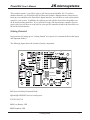
Getting Oriented
In preparation for setting up our “Getting Started” test system, let’s examine the PowerNut layout
and important features.
The following figure shows the location of major components.
C2
C8
+
+
U1
R19
R21
R14
C3
R20
R17
R18
R12
C7
C6
R9
Q4
R1
R22
Q1
Q5
JP1
R3
JP3
R8
C5
D1
Q2
U2
R7
Y1
R10
R6
R13
Q3
R11
WWW.JKMICRO.COM
+
J1
+
C1
R16
R5
C9
U3
DS2
HEARTBEAT
DS1
L1
LOW VOLTAGE
D3
VIN
J3
JP2
C10
+
R2
R15
J2
D2
R4
C4
D1 Reverse Polarity Protection Diode
Q2 and Q3 MOSFETs used to switch power
U2 PIC16LC710
DS1 Low Battery LED
DS2 Heartbeat LED
Getting Started
3
JK microsystems
PowerNut User’s Manual
JP1 Disable Protection Diode Jumper
JP2 not used
JP3 Downstream Voltage Configuration Jumpers
JP3 - Downstream Voltage Configuration Jumpers
Regulated 5 Volts
(Factory Default)
Raw Input Voltage
1-3
2-4
3-5
2-6
J1 Power Input Connector
J2 Downstream Voltage Connector
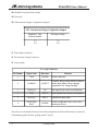
J3 Logic signals
J3 - Logic Connector
Pin Number
Signal Name
Direction
Function
1
GND
POWER
Ground connection
2
LOWBAT
OUTPUT
If enabled, this pin will go HIGH to indicate
that the input voltage is lower than the
programmed "low voltage threshold."
3
DATA_IO
I/O
Data signal for the clocked serial interface
4
CLK
INPUT
Clock signal for the clocked serial interface
5
DATA_IN
INPUT
Optional data input signal.
6
SWITCHED
RAW
POWER
Switched output that can be used to drive
downstream devices
Now that you can identify the major PowerNut components by name and function let’s proceed
with putting together the first “getting-started” system.
4
Getting Started
JK microsystems
PowerNut User’s Manual
Turning on the PowerNut
The first order of business is to configure the PowerNut’s downstream connector voltage to
supply suitable voltage for the target system. Jumpers on JP3 will need to be configured.
The factory default settings for JP3 are for 5 volt downstream operation. For our system, we
need to configure the downstream voltage to be approximately the same as the input voltage.
Configure the jumper blocks on JP3 so the “pins 3 and 5 are shorted” and “pins 2 and 6 are
shorted.”
Second, attach a load to the downstream connector. A digital volt meter (DVM) or digital
multimeter (DMM) is a suitable load. An LED with current limiting resistor is also a suitable
load. If you have the PowerNut development kit, you will find an LED with an internal currentlimiting resistor. The anode (positive leg) has red heatshrink on it.
Third, apply power to PowerNut. The PowerNut’s downstream connector will become
energized. This indicates that the PowerNut’s MOSFET switches (Q2 and Q3) and PIC
processor (U2) are operating correctly. You should use the DMM to verify the downstream
voltage is approximately equal to the input voltage.
A 200 mV to 500 mV drop from the input connector to the downstream connector is normal.
This is mostly caused by D1. In a production setting, D1 can be defeated by installing JP1, or by
installing a zero ohm shunt in an 0805 SMT package in R1.
Next, we setup a controller to talk to the PowerNut.
Getting Started
5
JK microsystems
PowerNut User’s Manual
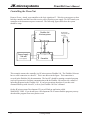
Controlling the PowerNut
Remove Power. Attach your controller to the logic signals on J3. Wire the system power so that
both the controller and the PowerNut receive power from the power supply. Do NOT attach your
controller to the downstream power connector. The following figure shows how the system
should be setup.
Flashlite 186
JK microsystems
J2
1
Downstream
Voltage Indicator
and Load
2
J9
Power Supply
7-30 volts
(user supplied)
+
1 J1
-
2
10
5
DATA IO
CLK
GND
1
1 2 3 4 5 6
J3
J2 2 +
PowerNut
1 -
This example assumes the controller is a JK microsystems Flashlite 186. The Flashlite 186 must
have a serial connection to a host PC. This is not shown in the figure. This connection is
covered in the Flashlite 186 documentation. The host PC should be running a terminal program
(such as Hyperterm) to facilitate communication with the Flashlite 186 and provide a means of
uploading programs to the Flashlite 186. If you have questions about how to set this serial
communication up with a host PC, refer to your Flashlite 186 User’s Manual.
On the JK microsystems Development CD you will find an application called
WAK10SEC.COM. If you do not have a Development CD or can not find the program you may
download the program from www.jkmicro.com.
6
Getting Started
JK microsystems
PowerNut User’s Manual
Use UP.COM on the Flashlite 186 and install WAK10SEC.COM on the Flashlite 186’s B: drive.
WAK10SEC.COM will use the Flashlite 186’s PIO 31 (J9-5) as a CLK for the PowerNut, and
PIO 1 (J9-10) as the DATA_IO line. The astute engineer will note that the Flashlite 186’s
documentation shows J9-5 as INT2. No need to be alarmed. The Flashlite 186 multiplex’s a
number of functions on this single pin and WAK10SEC.COM configures J9-5 as a general
purpose I/O port (PIO bit 31).
WAK10SEC.COM will send a command to the PowerNut to turn off the downstream power for
10 seconds.
When the power is first applied to the system, you should see a BIOS post from the Flashlite 186
on the host PC. You should also see the load LED lighted.
Run WAK10SEC.COM. The load LED should turn off for 10 seconds then turn back on. You
should also see the PowerNut’s heartbeat LED blink briefly every four seconds.
Using a DMM measure the voltage across the load and verify that it is suitable to power the
Flashlite 186 (7-30 volts).
Now that we have confirmed the PowerNut’s ability to shutdown and wake-up a downstream
device we will move on to a system in which the master controller receives power from the
PowerNut.
Getting Started
7
JK microsystems
PowerNut User’s Manual
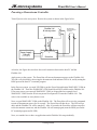
Powering a Downstream Controller
Turn off power to the test system. Rewire the system as shown in the figure below.
Flashlite 186
JK microsystems
J2
1
Downstream
Voltage Indicator
and Load
2
J9
Power Supply
7-30 volts
(user supplied)
+
1 J1
-
2
10
5
DATA IO
CLK
GND
1
1 2 3 4 5 6
J3
PowerNut
J2 2 +
1 -
As before, the figure does not show the serial connection between the host PC and the
Flashlite 186.
Apply power to the system. The PowerNut will turn on downstream power to the Flashlite 186.
You can verify this both by observing the downstream load indicator LED is lit, and by noting the
BIOS post on the host PC’s terminal program.
In the first test system, you used UP.COM to put the PowerNut application WAK10SEC.COM on
the Flashlite 186. Therefore WAK10SEC.COM should be still be available on the Flashlite 186.
If for some reason you removed WAK10SEC.COM (or skipped the last example) load
WAK10SEC.COM from the JK microsystems Development CD onto the Flashlite 186. This
code is also available at www.jkmicro.com.
Next, execute WAK10SEC.COM on the Flashlite 186. The PowerNut will receive the command
to turn off downstream power for 10 seconds. The PowerNut will then do so. The LED will go
dark, and the Flashlite 186 will be tuned off. After 10 seconds, the PowerNut will turn on power
to the downstream connector, and the Flashlite 186 will startup again (note the BIOS post on the
PC terminal program and lit LED).
Next, we consider how to have an application on the Flashlite 186 run periodically.
8
Getting Started
JK microsystems
PowerNut User’s Manual
Periodically Running an Application
The simplest method of running an application periodically is to place a call to the application in
the STARTUP.BAT file on the controller followed by a call to a program that will send a
command to the PowerNut to shutdown and subsequently wake the controller.
To illustrate this technique we will need a sample application. On the JK microsystems
Development CD, in the PowerNut sub-directory, there is a sample application called
SAMPAPP.COM. This is also available at www.jkmicro.com. Upload SAMPAPP.COM to the
Flashlite 186.
Execute SAMPAPP.COM on the Flashlite 186. Some text indicating that the sample application
ran and then terminated will be displayed.
To run SAMPAPP.COM periodically, we will place a call to SAMPAPP.COM in the
STARTUP.BAT file on the Flashlite 186 followed by a call to WAK10SEC.COM.
Using whatever technique you favor, create a STARTUP.BAT file on the Flashlite 186’s B: drive
that looks like:
PROMPT $P$G
PATH A:\;B:\;B:\BIN
SAMPAPP.COM
WAK10SEC.COM
A workable technique for creating this file is to use NOTEPAD on the host computer to create
the file, then use UP.COM to bring it over to the Flashlite 186.
With the new STARTUP.BAT file in place the system will run SAMPAPP.COM approximately
every ten seconds.
On boot the Flashlite 186 will execute AUTOEXEC.BAT from it’s A: drive. The last statement
in AUTOEXEC.BAT calls STARTUP.BAT. This file will execute the SAMPAPP.COM followed
by WAK10SEC.COM. This will cause the PowerNut to shut off the Flashlite 186 for 10 seconds
then turn it back on thus starting the process over again.
To begin the process, simply reset the Flashlite 186 by removing and reapplying power to the
system. Alternatively you can just type “boot” at the command prompt - no quotes.
If everything is functioning properly, you should observe the messages from SAMPAPP.COM
appearing on the host PC about every ten seconds.
Getting Started
9
JK microsystems
PowerNut User’s Manual
There is a small fixed time that is required for the Flashlite 186 to boot (about 400 ms), and for
the PowerNut to receive commands from the Flashlite (about 500 ms). This overhead will make
the actual period deviate from “10-seconds” somewhat. The overhead of booting and
communicating is less significant for longer sleep periods. In applications that require precise
timing the system developer can adjust the sleep-time through experimentation.
!
NOTE The PowerNut does not accept commands for one second after the
downstream connector is energized. This is to eliminate the possibility of
receiving erroneous commands due to noise on the clocked serial interface while
the downstream controller is initializing.
In the above example, the Flashlite 186 must run for at least a second before
executing the call to WAK10SEC.COM. Otherwise, the PowerNut will reject the
command to shutdown as noise associated with the Flashlite 186 powering-up.
The combination of boot code and SAMPAPP.COM provide the requisite one
second delay.
Hardware
General Theory of Operation
The heart of the PowerNut is a PIC16LC710 from Microchip Technology. This is a complete
microcontroller in an 18-pin SOIC package. The PowerNut runs the PIC16LC710 at 32768 Hz.
The PIC16LC710 monitors the CLK and DATA (DATA_IN and DATA_IO) signals for
commands. Each transmission is checked for validity by looking at the parity bit and verifying
the correct number of clock cycles occurred during the transmission. If the message is deemed
valid then during the last clock period of the communication the PowerNut will “turn around” the
DATA_IO signal and drive an ACK (high voltage) on to the DATA line.
Users that want to use a bidirectional signal for DATA can simply use DATA_IO. This was used
in the “getting started” examples.
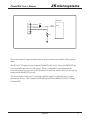
Users that want to use separate signals for data-in and data-out can use DATA_IN as PowerNut’s
data input, and DATA_IO as PowerNut’s data output. A quick glance at the figure on the facing
page shows that DATA_IN is “ORed” with DATA_IO through a diode. The pull-down resistor
ensures DATA_IO is held at a logic zero (LOW voltage) when DATA_IN is driven low and
DATA_IO is not driven.
10
Hardware
JK microsystems
PowerNut User’s Manual
PIC16LC710
J3
6
5
4
3
2
1
D2
DATA_IN
DATA
DATA_IO
R18
The section entitled Communications Protocol spells out the bit-level details of the message
traffic.
The PIC16LC710 supervises the P-channel MOSFETs (Q2 & Q3). These two MOSFETs are
wired in parallel and will act as one switch. When a command is received that tells the
PowerNut to turn on or off power to the Downstream connector, the PIC16LC710 does this by
turning off the MOSFETs on or off.
The PowerNut has a on-board +5 switching regulator capable of supplying up to 1 amp to
downstream devices. This is implemented with National Semiconductor’s LM2575 Simple
Switcher(TM).
Hardware
11
JK microsystems
PowerNut User’s Manual
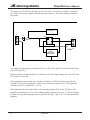
The jumpers on JP3 allow the developer to select between “switched raw voltage” or regulated
five volts as the voltage supplied to the downstream connector. The following figure illustrates
the wiring.
PIC16LC710
J1
D1
JP3
1
2
Q2 & Q3
1
2
3
4
5
6
J2
2
1
J3-6
V
IN
5 VOLT
SWITCHING
REGULATOR
VOUT
To configure the downstream voltage on J2 to be 5 volts, JP3-1 and JP3-3 must be shorted along
with JP3-2 and JP3-4.
If the downstream voltage should be a switched version of the input voltage on J1 then JP3-4 and
JP3-6 must be connected.
If the application requires both five volts and “switched raw” the PowerNut can provide this.
Configure JP3 to provide regulated 5 volts on the downstream connector (J2). The application
will have access to “switched raw” on J3-6.
If the application does not require the 5 volt switching regulator to be active, JP3 pins 1 and 3
should be unconnected so the 5 volt switching regulator consumes no power. To save the jumper
for future use, the physical jumper may be placed on JP3 pins 3 and 5. JP3-5 is not connected to
anything.
12
Hardware
JK microsystems
PowerNut User’s Manual
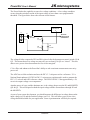
The PowerNut has the capability to sense low voltage conditions. A low voltage condition
occurs when the switched version of the input voltage is lower than a user programmable
threshold. The figure below shows the relevant circuit features.
PIC16LC710
A IN
J1
D1
TO OTHER
DOWNSTREAM
COMPONENTS
1
2
Q2 & Q3
R2
10.0 K
C4
100 NF
R4
1.00 K
The voltage divider composed of R2 and R4 is placed after the downstream control switch (Q2 &
Q3). This means that a low voltage test may only occur when Q2 & Q3 are “closed.” This was
done to save power when downstream devices are de-energized.
C4 is a filter and enhances the PowerNut’s ability to take consistent measurements on a noisy
power rail.
The ADC has an 8-bit resolution and uses the PIC’s 3.3 volt power rail as a reference. U1 is
National Semiconductor’s LP2951ACM-3.3 micropower regulator and is used to generate the
PIC’s 3.3 volt rail and ADC reference voltage. The LP2951ACM-3.3 has approximately a 1%
error in its output voltage over temperature.
Another source of error, and the dominate one, is the voltage drop across the D1 and MOSFETs
(Q2 & Q3). This will depend on both the input voltage and the current drawn through D1 and
the MOSFETs.
As part of your system development, you should measure the difference in voltage between the
input voltage (on J1) and the switched voltage (on J3-6). This will allow you to select a low
voltage threshold suitable for your application. Some experimentation will likely be required.
Hardware
13
JK microsystems
PowerNut User’s Manual
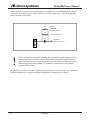
If the voltage drop across reverse polarity protection diode (D1) is problematic the D1 may be
defeated by installing a slip-on jumper on JP1 or an SMT jumper in R1. The following figure
shows relevant circuit details.
R1
Optional
ZERO OHM
0805 SMT resistor
JP1
0.100" slip on jumper
J1
D1
1
To remaining
PowerNut electronics
2
!
If D1 is defeated, it is possible to damage the PowerNut by applying input power of
the wrong polarity. JK microsystems recommends defeating D1 only in systems
where the drop across D1 can not be tolerated, and then only in production systems.
While doing system development, it is prudent to maintain the reverse polarity
protection D1 provides.
Defeating D1 will affect your low voltage threshold settings for the low battery test. Additional
experimentation may be required during development to accommodate the change.
14
Hardware
JK microsystems
PowerNut User’s Manual
Jumpers and Connectors
JP1 is a two pin jumper. If this jumper is installed (shorted) then D1 is defeated and the board
will have no reverse polarity protection. With D1 shorted
it will not contribute a voltage
drop between the input power connector and the downstream connector. JK microsystems
recommends leaving JP1 open during development thus retaining the reverse polarity protection.
During production JP1 can be installed in applications where squeezing millivolts from a battery
is more important than the reverse polarity protection offered by D1.
JP2 is a two pin jumper. It is not used in the current version of the PowerNut.
JP3 contains the Downstream Configuration Jumpers.
JP3 - Downstream Voltage Configuration Jumpers
Regulated 5 Volts
(Factory Default)
Raw Input Voltage
1-3
2-4
3-5
2-6
J1 is the Power Input Connector. J1 is a two position 5 MM screw terminal and is capable of
accepting solid or tinned wire from 14 AWG to 24 AWG.
J1 - Power Input Connector
Pin Number
Signal
Name
Direction
1
V+
POWER
+5 to +30 volts (+7 to +30 if on-board
5 volt regulator is used)
2
GND
POWER
Current Return (GROUND)
Function
Hardware
15
JK microsystems
PowerNut User’s Manual
J2 is the Downstream Voltage Connector. J6 is a two position 5 MM screw terminal and is
capable of accepting wire size from 14 AWG to 24 AWG.
J2 - Downstream Voltage Connector
Pin Number
Signal
Name
Direction
Function
1
GND
POWER
Current Return (GROUND)
2
VDOWNSTREAM
POWER
Downstream Voltage as set by JP3 jumpers
J3 is the PowerNut’s Digital interface.
J3 - Logic Connector
Pin Number
Signal Name
Direction
1
GND
POWER
Ground connection
2
LOWBAT
OUTPUT
If enabled, this pin will go HIGH to indicate
that the input voltage is lower than the
programmed "low voltage threshold."
3
DATA_IO
I/O
Data signal for the clocked serial interface
4
CLK
INPUT
Clock signal for the clocked serial interface
5
DATA_IN
INPUT
Optional data input signal.
6
SWITCHED
RAW
POWER
Switched output that can be used to drive
downstream devices
16
Function
Hardware
PowerNut User’s Manual
JK microsystems
Communications Protocol
The PowerNut uses a clocked serial interface to receive commands. This interface consists of a
CLK input and a bidirectional DATA_IO signal and an optional DATA_IN signal. Target
systems may be developed to use the single bidirectional DATA_IO signal, or to use DATA_IN
as a dedicated input and DATA_IO as a dedicated output.
The controller issuing commands to the PowerNut is considered the “master,” and is responsible
for generating the CLK signal. Messages to the PowerNut consist of a start-bit, an even parity
bit, 3-bit command, and 16-bit operand. Following a message the master generates one
additional CLK pulse and the PowerNut drives the DATA_IO line high or low to indicate an
acknowledge (ACK) or error (NACK).
The CLK pulses must be between 22 milliseconds and 80 milliseconds in duration, and as close
to a 50% duty cycle as possible. This implies that the minimum time for a message to be
transmitted is about half a second (1 start bit + 1 parity bit + 3-bit command + 16-bit operand +
ACK = 22 x 22 ms = 484 ms).
Some controllers have large “ride through” capacitors that will carry a controller through a brown
out condition for a short period of time - tens or hundreds of milliseconds. These controllers can
randomly bounce around CLK and DATA_IO (or DATA_IN) for a fairly long period of time as
power goes down or comes up. For this reason, the PowerNut ignores traffic on the clocked
serial interface for one second after power is turned-off or turned-on to the downstream
connector.
The PowerNut is capable of accepting and processing commands regardless of the state of
downstream power. A master controller capable of controlling power to devices other than itself
may “prematurely” wake-up a device by sending the appropriate command (SHUTDOWN for
ZERO seconds).
Communications Protocol
17
JK microsystems
PowerNut User’s Manual
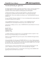
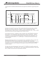
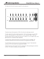
To help visualize communication blackout times the figure below illustrates a typical sleep/wake
cycle.
CLOCKED
SERIAL BUS
READY
BUS IDLE
BLACKOUT
SLEEP
CMD
BLACKOUT
READY
BUS IDLE
BLACKOUT
READY
BUS IDLE
V DOWNSTREAM
V IN
SECONDS
0
1
T_SLEEP
(T_SLEEP+0.5)
(T_SLEEP + 1.5)
T_WAKE
(T_WAKE + 1)
Just prior to 0 seconds, Vin comes up. This resets the PowerNut’s processor and very shortly
thereafter, the downstream connector is energized. At the 0 second mark in the figure,
downstream power is turned on and a 1 second communications blackout starts. At the 1 second
mark the PowerNut will accept commands on the clocked serial bus.
Some arbitrary time later (T_SLEEP) the master controller sends a SHUTDOWN command to
the PowerNut. The command takes approximately half a second to communicate. After the
command is received, the PowerNut de-energizes the downstream devices and imposes a one
second communications blackout. At T_SLEEP plus 1.5 seconds, the PowerNut will accept
commands again.
When the downstream connector is de-energized, the only command that will be executed is the
SHUTDOWN for ZERO seconds command. Other commands maybe sent while the
downstream devices are de-energized, and the PowerNut will provide an ACK indicating that the
command was received, but all commands will be ignored except a SHUTDOWN for ZERO
seconds command..
The figure shows that at the appointed “wake-up time” (T_WAKE) the PowerNut energizes the
downstream connector. This is followed by a one second communications blackout. One second
after T_WAKE, the PowerNut will accept further commands.
18
Communications Protocol
PowerNut User’s Manual
JK microsystems
After the receipt of a message, the PowerNut will be unable to receive another message for a
maximum of one second. This means that for reliable communications the master should send
commands spaced at least one second apart. Most commands are processed in much less than a
second, but a one second spacing of commands ensures reliable operation.
If the target system drives DATA_IN and listens to DATA_IO then the target system doesn’t have
to worry about “releasing” DATA_IO for the PowerNut to be able to drive it for the ACK/NACK
phase. Such a target system only has to read the ACK or NACK on DATA_IO at the appropriate
time. In such a system, DATA_IO will be driven HIGH by driving DATA_IN HIGH. DATA_IO
will be pulled LOW by driving DATA_IN low.
For the remainder of this document, we will speak of driving DATA_IO to a state. The reader
must bear in mind that this can be do by either driving DATA_IO directly, or by driving
DATA_IN.
The master initiates all communications with the PowerNut. The master is responsible for
generating the CLK. The PowerNut looks for a rising edge on CLK and a LOW value on
DATA_IO to mark the start of a transmission. The PowerNut clocks in DATA_IO on subsequent
rising edges or CLK. On the 23rd rising edge of CLK, the PowerNut turns around DATA_IO and
drives an ACK or NACK. On the next falling edge on CLK (the 23rd falling edge) the PowerNut
release DATA_IO.
Communications Protocol
19
JK microsystems
PowerNut User’s Manual
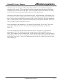
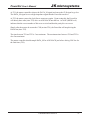
The figure below shows the sequence required for each transaction.
T23
T0
T1
T2
T3
T4
T5
T6
T20
T21
T22
T25
T24
...
CLK
DATA
T19
START
PARITY
CMD0
CMD1
CMD2
DATA0
DATA1
...
DATA15
ACK/
NACK
T0 marks the start of the transaction. DATA_IO is driven low indicating a start-bit.
T1 marks when the PowerNut samples the parity bit. The PowerNut expects to see an EVEN
parity bit. This means that if we count all of the 1’s in the command (CMD0..CMD2) and
operand (DATA0..DATA15) and the parity bit, then we will have an “even” number of bits. Note
that the start-bit is excluded from this computation.
T2 marks the time when the PowerNut receives the first bit of the 3-bit command. The
command is transmitted on the clocked serial interface least significant bit (LSB) first.
T3 and T4 indicate when the next two bits of the command are accepted. Note that the bit
clocked in at T4 is the command’s most significant bit (MSB).
T5 indicates the start of the operand. Like the command, the 16-bit operand appears on the bus
LSB first. T20 marks the sampling of the operand’s MSB.
20
Communications Protocol
PowerNut User’s Manual
JK microsystems
At T21, the master controller releases the DATA_IO signal and causes the CLK signal to go low.
The DATA_IO signal is now a high-impedance signal that the PowerNut can drive.
At T22, the master causes the clock line to assert once again. Upon seeing this, the PowerNut
will shortly there after (time T23) drive an ACK/NACK onto the bus. An ACK (HIGH level)
indicates that the correct number of bits were received and that the parity bit was correct.
Shortly after the master de-asserts the CLK (at time T24), the PowerNut will stop driving the
DATA line (time T25).
The time between T22 and T23 is 5 ms maximum. The maximum time between T24 and T25 is
also 5ms maximum.
The master controller should sample DATA_IO for ACK/NACK just before driving CLK low for
the final time (T24).
Communications Protocol
21
JK microsystems
PowerNut User’s Manual
Commands and Capabilities
The PowerNut has several different commands. This section discusses each command in detail.
Shutdown
CMD: 001 (0x01)
OPERAND: 0x0000 To 0xFFFF
This command will cause the PowerNut to de-energize the output connector and wait the number
of seconds specified in the operand before energizing the output connector again.
The 16-bit field will allow the device powered by the Power Nut to be shutdown for 1 second to
18.2 hours with 1-second resolution.
Note that the operand 0x0000 is allowed. If an operand of 0x0000 is received by the PowerNut,
the output connector will be energized. If the system is designed such that a powered master is
talking to the PowerNut while the downstream connector is de-energized, a “shutdown for zero
seconds” command may be used to reenergize the downstream connector prior to the scheduled
wake up time.
Set configuration word
CMD: 010 (0x02)
OPERAND: 0x0000 To 0x00FF
This command allows the behavior of the PowerNut to be modified through a configuration
word. If this command is received while the downstream power connector is de-energized, then
the command is ignored. The format of the configuration word is shown in the table.
BIT
22
15 14 13 12
11
10
FUNCTION
*
*
*
*
*
Heart-beat
LED
enable
DEFAULT
VALUE
0
0
0
0
0
1
9
8
Low Voltage Low Voltage
LED
SIGNAL
enable
enable
0
0
Communications Protocol
7 6 5 4 3 2 1 0
Low Voltage
Threshold
0x43
10 volts
JK microsystems
PowerNut User’s Manual
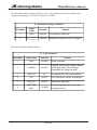
BITs 7..0 The eight-bit Low Voltage Threshold is a binary code corresponding the PowerNut’s
analog to digital converter’s codes. The following codes are typical.
Binary Code Low Voltage Threshold (volts)
0x35
8.0
0x43
10.0
0x99
22.0
Bit7 is the most significant bit, while Bit0 is the least significant. The default value of the low
voltage threshold is set to 0x43 which translates to approximately 10 volts.
BIT 8 Setting this bit enables the Low Voltage signal J3-2. The default value of this bit is
ZERO. If this bit is ZERO, then J3-2 will never be driven high regardless of the low battery
condition. It is good practice to disable this bit before de-energizing the downstream connector
to prevent bleed-through. Bleed-through is a condition in which a downstream device is deenergized but still bleeds power through a signal pin. This condition is also referred to as a
device being parasitically powered, or being powered through a sneak-path. This is an
undesirable condition and should be avoided. See the Guidelines for Reliability section of this
manual.
BIT 9 Setting this bit enables the Low Voltage LED. The default value of this bit is ONE. If
this bit is set to a ONE, the Low Voltage LED will light if the results of the next low voltage test
indicate the measured voltage is below the Low Voltage Threshold. If the LED is in a nonvisible location, this bit can be cleared (to a ZERO) and then the Low Voltage LED will not light
under any circumstances. This will save power. It may be desirable to clear this bit before
putting down stream devices to sleep.
BIT 10 Setting this bit enables the Heartbeat LED. Default Value is ONE. If this bit is set, the
heartbeat LED will flash once every four seconds when the PowerNut has de-energized its output
connector. If a human is present, this provides a visual indication that the PowerNut is operating
properly. If a human is not available under normal operating conditions, then the Heartbeat LED
may be disabled to save battery power.
BIT 11..15 These bits are reserved for future use.
Communications Protocol
23
JK microsystems
PowerNut User’s Manual
Perform Low-Battery Test
CMD: 101 (0x05)
OPERAND: 0x0000 To 0xFFFF
This command initiates a low-battery test. The operand is ignored.
A low-battery test may only be performed when the downstream connector is energized. If this
command is received while the downstream power connector is de-energized, then this command
will be ignored.
A low-battery test compares the voltage after the “main switch” (MOSFETs Q2 & Q3 see the
Hardware section of this manual) to the low voltage threshold in the lower 8-bits of the
PowerNut’s configuration register.
If the measured value is equal to or greater than the threshold voltage set in the configuration
register, then no action is taken.
If the measured voltage is less than the threshold voltage in the configuration register, then the
Low Power LED is lit if enabled, and the Low Power Signal (J3-2) is driven HIGH if enabled.
Both the Low Power LED and the Low Power Signal (J3-2) can be enabled or disabled by bits in
the configuration register.
24
Communications Protocol
JK microsystems
PowerNut User’s Manual
Guidelines for Reliability
To ensure reliable operation of the PowerNut, JK microsystems offers these guidelines.
1. A bit time of 50 ms seems to offer excellent reliability and should be easily generated by any
controller.
2. DATA_IO (or DATA_IN) should make its transition as close to falling edges of CLK as
possible.
3. CLK’s duty cycle should be as close to 50% as possible.
4. DATA_IO (or DATA_IN) line has a minimum setup time of 5 ms before the rising edge of
CLK.
5. DATA_IO (or DATA_IN) line has a minimum hold time of 10 ms after the rising edge of
CLK.
6. Wait two seconds after power is first applied to the PowerNut before sending commands.
This will give the PowerNut’s on-board processor time to reset and initialize.
7. If the low-battery test is going to be used and the Low Voltage Signal J3-2 is connected to the
device receiving power from the downstream connector, you MUST disable the Low Voltage
Signal before de-energizing the downstream connector. Failure to do this will result in a
condition called “bleed through” whereby the device that is supposed to be shut off draws
excessive current from the I/O pin connected to J3-2. This will result in wasted power. This
may result in the downstream device not turning off completely. This may result in the
downstream device not resetting correctly on power-up. In some very rare cases, it may
result in damage to the PowerNut and/or to the downstream device. ALWAYS disable the
Low Voltage Signal before de-energizing the downstream connector, if J3-2 is connected to a
device that is downstream of the PowerNut.
8. Allow one second between messages.
9. The PowerNut ignores messages for one second after turning on or off downstream power.
Avoid sending messages during this time.
10. Check the ACK/NACK on each message. If the master does not receive an ACK, then wait
TWO seconds and send the message again. This will avoid the condition in which the master
requests that power be turned off and then does not check the ACK and enters a loop of some
kind but the message was garbled and the PowerNut ignored it, thus not shutting down
power. This condition can be very difficult to recover from unless there is a watchdog on the
master.
Guidelines for Reliability
25
JK microsystems
PowerNut User’s Manual
Software
Software running on a “master” controller directs the PowerNut’s behavior. This section
describes software that is available from JK microsystems. This section also discusses briefly
how to modify the available software.
All executables and source files are available for all the utilities at www.jkmicro.com.
The files are also available on the PowerNut Development CD.
All other JK microsystems “Development CDs”contain these files in the
\JKmicro\Accessories\PowerNut directory.
NUTCOMM
JK microsystems provides a utility for the Flashlite 186. This utility is called
NUTCOMM.COM. The full source code is also available - NUTCOMM.ASM (also required is
186_IO.asm). This utility was written in assembly language so that the executable’s footprint
would be as small as possible.
Just typing NUTCOMM.COM at the command prompt will generate a few lines of text
explaining how to use this utility. The usage is: NUTCOMM <command> <param>. Both the
command and param field are case insensitive.
NUTCOMM.COM accepts “sleep”, “config” and “lptest” as commands. These correspond to
the PowerNut’s “shutdown”, “set configuration word” and “Perform Low-Battery Test”
commands.
The <param> field is the 16-bit operand to be sent with the command. This field is interpreted
as hexadecimal. This field is at most four digits and contains no “0x” prefix or “h” suffix. There
is no need to add leading numeric digits to alpha characters that are part of the hexadecimal
number.
All of the following are valid parameters {0, 00, 000, 0000, a, 0a, 000a, FED, 0FED). The
following are not valid (0x0000, 0Ah, 0FFFF).
Examples of commands are:
NUTCOMM SLEEP A {sleep for 10 seconds}
NUTCOMM SLEEP 0 {wake up}
NUTCOMM LPTEST 0000 {perform a low battery test}
26
Software
JK microsystems
PowerNut User’s Manual
NUTCOMM will allow a Flashlite 186 to operate a PowerNut from the command line or batch
files. However, NUTCOMM does expect that the Flashlite 186 be connected to the PowerNut in
a prescribed manner. If you have a different controller, or wish to simply use different IO pins,
you can modify NUTCOMM to suit your requirements.
All of the hardware specific subroutines for NUTCOMM can be found in 186_IO.ASM. Simply
by modifying this file, you will be able to change which port pins are used for CLK and DATA.
JK microsystems used MASM (Microsoft Macro Assembler 5.0) to build NUTCOMM.COM.
However, any x86 assembler should be able to handle the code in NUTCOMM.ASM and
186_IO.ASM.
WAK10SEC
WAK10SEC.COM is will send a “shutdown for 10 seconds” command to the PowerNut.
WAK10SEC does expect that the Flashlite 186 be connected to the PowerNut in a prescibed
manner. If you have a different controller, or wish to use different IO pins or wish to modify the
command sent, you can modify the WAK10SEC source code to suit your requirments.
All of the hardware specific subroutines for WAK10SEC can be found in 186_IO.ASM. Simply
by modifying this file, you will be able to change which port pins are used for CLK and DATA.
JK microsystems used MASM (Microsoft Macro Assembler 5.0) to build WAK10SEC.COM.
However, any x86 assembler should be able to handle the code in WAK10SEC.ASM and
186_IO.ASM.
CNUT
Is a utility that allows a controller to send commands to a PowerNut. This utility is functionally
equivalent to the NUTCOMM utility. CNUT was written entirely in C. The drawback of this is
that the footprint of the executable is larger than that of NUTCOMM.COM. The hand coded
assembly of NUTCOMM generates about a 2.3K byte executable and CNUT.EXE is 38K bytes.
However, some users may find modifying a C program, or porting it to another platform easier
than manipulating the NUTCOMM assembly source code.
Software
27
JK microsystems
PowerNut User’s Manual
Specifications
Supply Voltage
5-30 VDC if not using the on-board 5 volt switching regulator
7-30 VDC otherwise
Downstream shutoff : 180µA max (58 to 100µA typical)
Downstream active, on-board 5V disabled, Vin=5V, 3.3mA
Downstream active, on-board 5V disabled, Vin=30V, 7.5mA
Downstream active, on-board 5V active, Vin=7V, 11mA
Downstream active, on-board 5V active, Vin=30V, 15mA
Current Consumption
with no load attached
Operating Temperature
Humidity
-20 to +85 °C
5 - 90% non-condensing
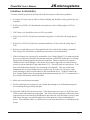
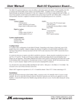
Physical dimensions
mounting holes
2” x 3” x 0.6”
#6 hardware - 4 places
Mechanical Drawing
C2
C8
+
+
U1
C3
R20
R17
R18
R19
R21
R14
R12
C7
C6
R9
Q4
R1
Q1
U2
R7
Q5
JP1
R3
JP3
R8
C5
D1
Q2
R22
Y1
R10
R6
R13
Q3
R11
2.00"
+
J1
1.80"
+
C1
WWW.JKMICRO.COM
R16
R5
C9
U3
DS2
HEARTBEAT
DS1
L1
LOW VOLTAGE
D3
VIN
C4
0.20"
2.80"
3.00"
0.60" TYP
28
Specifications
R15
C10
+
R2
R4
0.20"
J3
JP2
J2
D2
JK microsystems
PowerNut User’s Manual
Contact Information
JK microsystems, Inc.
1403 Fifth Street, Suite D
Davis, CA 95616
Telephone:
Fax:
Email:
Web:
Rev
----1.0
(530) 297-6073
(530) 297-6074
[email protected] (sales inquiries)
[email protected] (technical support)
http://www.jkmicro.com
Date
--------03/03/03
Author
-------BP
Changes
----------------------------------------------------Initial Release
Contact and Revision Information
29