1
DS-CP25
USER’S MANUAL
L IN
R IN
L OUT
R OUT
LCOMP
DS-CP25
R COMP
®
USB
Multi-Band Compressor
19"
(482mm)
DIGITAL
USB
Contents
Introduction..........................................................................................1
Safety Instructions................................................................................ 2
Overview...............................................................................................3
Getting Started with Front Panel Controls........................................ 4 - 31
Using the PC Interface.................................................................. 32 - 37
Specifications..................................................................................... 38
Introduction
Thank you for choosing a Galaxy DSPOT Digital Signal Processor. You have joined
hundreds of thousands of other satisfied Galaxy customers. Since 1977 Galaxy Audio’s
professional experience in design and manufacturing ensure our products’ quality,
performance and reliability.
For the most up to date manual and information
visit www.galaxyaudio.com.
1
Safety Instructions
This symbol indicates that there are important
Operating and maintenance instructions in the
Literature Accompanying This Unit
This symbol indicates that dangerous voltage
Constituting a risk of electric shock is present
within this unit.
! IMPORTANT SAFETY INSTRUCTIONS !
1.
2.
3.
4.
5.
6.
7.
READ these instructions.
KEEP these instructions.
HEED all warnings.
FOLLOW all instructions.
DO NOT use this apparatus near water.
CLEAN ONLY with dry cloth.
DO NOT block any ventilation openings. Install in accordance with the manufacturer's instructions.
8. DO NOT install near any heat sources such as radiators, heat registers, stoves,
or other apparatus (including amplifiers) that produce heat.
9. DO NOT defeat the safety purpose of the polarized or grounding-type plug. A
polarized plug has two blades with one wider than the other. A grounding type
plug has two blades and a third grounding prong. The wider blade or the third
prong are provided for your safety. If the provided plug does not fit into your
outlet, consult an electrician for replacement of the obsolete outlet.
10. PROTECT the power cord from being walked on or pinched, particularly at plugs,
convenience receptacles, and the point where they exit from the apparatus.
11. ONLY USE attachments/accessories specified by the manufacturer.
12.
USE only with a cart, stand, tripod, bracket, or table
Specified by the manufacturer, or sold with the
Apparatus. When a cart is used, use caution when
moving the cart/apparatus combination to avoid
injury from tip-over.
13. UNPLUG this apparatus during lightning storms or when unused for long periods of
time.
14. REFER all servicing to qualified service personnel. Servicing is required when the
apparatus has been damaged in any way, such as power-supply cord or plug is damAged, liquid has been spilled or objects have fallen into the apparatus, the apparatus
has been exposed to rain or moisture, does not operate normally, or has been
dropped.
15. DO NOT expose the apparatus to dripping and splashing. DO NOT put objects filled
with liquids, such as vases, on the apparatus.
16. Remove the batteries from the receiver if the system will not be used for a long
period of time. This will avoid any damage resulting from a defective, leaking
battery.
17. DO NOT throw used batteries into a fire. Be sure to dispose of or recycle used
batteries in accordance with local waste disposal laws.
2
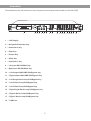
Overview
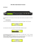
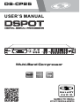
Described below are the functions of the front panel control buttons and encoders for the DS-CP25.
L IN
R IN
DS-CP25
L OUT
R OUT
LCOMP
R COMP
®
USB
1
2 3 4
5
6
1 - LCD Display
2 - Navigation/Parameter Key
3 - Parameter 2 Key
4 - Enter Key
5 - Escape Key
6 - Utility Key
7 - Parameter 3 Key
8 - Left Input EQ Edit/Mute Key
9 - Right Input EQ Edit/Mute Key
10 - Left Output LIM/COMP Edit/Bypass Key
11 - Right Output LIM/COMP Edit/Bypass Key
12 - Left Single Band Comp Edit/Bypass Key
13 - Left 2 Band Comp Edit/Bypass Key
14 - Left 3 Band Comp Edit/Bypass Key
15 - Right Single Band Comp Edit/Bypass Key
16 - Right 2 Band Comp Edit/Bypass Key
17 - Right 3 Band Comp Edit/Bypass Key
18 - USB Port
3
7
8 9
10 11 12 13 14 15 16 17 18
Getting Started
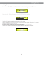
• Getting Started
As soon as the DS-CP25 is turned ON, the device model name will appear in the LCD screen:
Multi-Band Compressor
DSP Processor
And a status bar will show the progress of the DS-CP25 initialization process:
Multi-Band Compressor
The DS-CP25 has the possibility to store/recall up to 20 presets.
After the initialization, the DS-CP25 will show current preset, if any available. Otherwise, if no presets
available, it will start showing “Preset 01”.
Also, the DS-CP25 can work as a 2 or 3 multi band compressor or as Mono band.
By default, the unit is starting as 3 bands stereo compressor.
The first time activation, will default to the following page and 3 band stereo compress.
Multi-Band Compressor
Preset 01
4
• Encoders and ENTER, ESC buttons
The DS-CP25 is equipped with 3 Relative Encoders, “NAV/PM1”, “PM2” and “PM3”. These encoders
allow you to navigate the user interface and edit sections of the processor. They allow the user to
navigate within the screen for the selection of sub-menus, pages and parameters and to select the
values to be assigned during the editing operations.
The “ENTER” and “ESC” buttons allow the user to confirm or NOT confirm the operations performed by the
encoders.
• UTILITY, EQ Edit/Mute [2] and Lim/Comp Edit/Bypass [8] buttons
The UTILITY button allows the User to enter the Sub-menus and set the general characteristics of the
Processor. The EQ Edit/Mute buttons allow the User to enter the Editing Menus of the DS-CP25’s input
Channels EQ Section and Outputs Mute, and buttons Lim/Comp Edit/Bypass allow the User to enter the
Editing Menus of the DS-CP25's RMS Compressors, Output Limiter and Compressors Bypass.
The EQ Edit/Mute buttons as well as the Lim/Comp Edit/Bypass buttons have double functions dependent
on the push and hold time.
When the EQ Edit/Mute buttons are pushed and held for more than two seconds, Input Channels LIN or
RIN are either muted or unmuted. The red LED will illuminate when the Channel is muted.
When the “MUTE” LED is OFF, then the related Input Channel is UN-MUTED.
A momentary push of the EQ Edit/Mute buttons enters the Editing Mode for the DS-CP25’s Input Channels
Eq Section (see later for the Input Channel Editing details). The blue “EDIT” LED will now be ON.
When the Lim/Comp Edit/Bypass buttons are pushed and held for more than two seconds, the related
Compressor’s Output is either muted or unmuted. The red LED will illuminate when the selected
Compressor’s Output is MUTED. When the “MUTE” LED is OFF, then the related Compressor’s Output
Channel is UN-MUTED.
A momentary push of the Lim/Comp Edit/Bypass buttons enters the Editing Menu for the related
Compressor (see later for the Output Channel Editing details). The blue “EDIT” LED will now be ON.
• DS-CP25 Menu and Sub-Menu Structures
As stated above, the start-up default screen is the currently running preset or, if the device is new, the flat
“Preset 01” preset:
Multi-Band Compressor
Preset 01
From this point, sub-menus are accessed using the “UTILITY”, “EQ Edit/Mute”, “Lim/Comp Edit/Bypass”,
“ENTER” and “ESC” buttons and all parameters and values are navigated by the “NAV/PM1”, “PM2” and
“PM3” encoders.
5
MENU “LCOMP/RCOMP” RMS Compressors Editing [Access by pushing the “Lim/Comp” “Edit/Bypass” buttons]
This Menu is related to the editing of the RMS compressors parameters and to the selection of the number
of bands for the DS-CP25 compressor to work with. The DS-CP25 can work as Monoband, 2 or 3 bands
stereo compressor.
If the DS-CP25 has been set as Monoband compressor, no choice is allowed for the X-Over frequencies
used for the band division in Multi band mode, and ONLY the FIRST of the 3 available compressor is
editable.
If the DS-CP25 has been set as 2 bands compressor, the user can set the X-Over frequency used for the 2
bands creation and ONLY the FIRST and SECOND of the 3 available compressors are editable.
If the DS-CP25 has been set as 3 bands compressor, the user can set the X-Over frequencies used for the
3 bands creation and ALL the 3 available compressors are independently editable.
The selection of the Compressor type and the eventual X-Over frequencies can be done from any one of
the compressors’ editable pages and it is linked to the other 2 compressors editing pages.
So, if selected the number of bands in the editing environment of the Compressor 1, the choice will be
replicated on the editing environments of the Compressors 2 and 3. So, if the Monoband Compressor is
selected from the editing environment of the Compressor 3, the environment will be no longer accessible in
the all compressor’s parameters and to edit the Monoband compressor will be necessary to access the
editing environment/pages of the Compressor 1.
• Menu “UTILITY” [access by pushing the “UTILITY” button]
From the “Default Screen”, it is possible to access the “UTILITY” menu by pushing the “UTILITY” button
and the Sub-Menus pages can be selected by rotating clockwise and counter-clockwise the “NAV/PM1”
encoder.
Upon selecting the sub-menu page, using the “ENTER” button, the sub menus can be accessed again
“scrollable” using the “NAV/PM1” encoder and accessible for parameter editing by again pushing the enter
button.
Through the “ESC” button, it is possible at any time to go back to the action and page preceding the
“ENTER” button use.
Once inside the Sub-Menus pages, the several options can be scrolled through using the “PM2” or “PM3”
encoders and selected/confirmed pushing the “ENTER” button.
Note: In every Sub-Menu the option currently selected/running will have an Asterisk “*” showing to the
right of the description on the LCD screen.
Options that are not selected/running will be not be displayed with Asterisk.
Pushing the ENTER button on an unselected option will mean an asterisk will then appear and this option
will now take over as the currently selected/running option.
System Utilities Sub-menu - this sub-menu allows to access several operations related to the DS-CP25
Start Up and General Configuration:
UTILITY MENU:
System Utilities
6
From the “System Utilities Sub-menu”, pushing “ENTER” and then using the “NAV/PM1” encoder for
scrolling will give access to the following pages:
Power-On Procedure - this gives you the ability to select the option that will apply when the DS-CP25
powers up after being switched on:
SYSTEM UTILITY:
Power On Procedure
By pressing “ENTER” and rotating the “PM2” or “PM3” encoder, it is possible to choose between two
options: “Fade In On” or “Fade In Off”.
The currently running option will be displayed with an Asterisk to the right of the option description.
To change the option, simply ENTER on the option not displaying the Asterisk and that option will become
active and an Asterisk will now appear to the right of the option description.
The following two options are available:
FADE-In = Off - when the DS-CP25 is turned on, all Outputs regardless of their status before the Unit was
switched off, will be MUTED or UNMUTED automatically, meaning the DS-CP25 will have no active
Outputs, or active Outputs during the start-up process, depending on the Outputs’ previous status.
FADE-In = On - when the DS-CP25 is turned on, all Outputs not previously muted before the Unit was
switched OFF will be active. Meaning the DS-CP25 outputs will be controlled by a volume ramp to avoid
any sudden sound. If the option “Fade-In = On” is selected, the screen will show the following:
Power-On Procedure
Fade-In: On
Delay Time/Distance - this page allows you to select the measurement unit to be used for the Delays:
Time (in milliseconds “ms”) or Distance (in meters “m”)
SYSTEM UTILITY:
Delay Units
By pressing ENTER and rotating the “PM2” or “PM3” encoder, it is possible to select the measurement unit
to be used for the delay, which will be confirmed by pushing the “ENTER” button.
The following screen that shows the selected delay measurement is Time (milliseconds):
Delay Units
Unit: Time (ms)
7
Input Routing - the DS-CP25 Processor is equipped with 2 Analog Inputs (Balanced Female XLR) and a
stereo S/PDIF Digital Input (RCA connector).
The “Routing Options” page allows you to select the desired Input type:
SYSTEM UTILITY:
Input Routing
By pressing “ENTER” on Input Routing and then rotating the “PM2” or “PM3” encoder, it is possible to
select the Main Inputs for the DS-CP25, allowing the User to choose between Analog or S/PDIF Digital.
The selection can be confirmed by pressing the “ENTER” button.
The following screen shows that the Analog Input has been selected:
Input Routing
Source: Analog
Software Version - this page allows you to confirm the Software Version running on the DS-CP25:
SYSTEM UTILITY:
Software Version
Program Utilities Sub-menu - this sub-menu allows you to access several options related to the DS-CP25
operating mode and to manage the presets stored and recall-able within the Unit:
UTILITY MENU:
Program Utilities
By pressing the “ENTER” button and then using the “NAV/PM1” encoder the following pages can be
accessed:
Recall a Program - this page allows the Loading of a preset program. You can store up to 20 Presets in
the DS-CP25 memory:
PROGRAM UTILITY:
Recall a Program
By pressing “ENTER” and rotating the “PM3” encoder, it is possible to scroll through all current available
user presets. If NO USER PRESETS are stored yet, the screen will show the following:
Recall a Program
No Stored Programs
8
If presets have previously been stored by the user, any one of them can be recalled:
[ENTER] to Recall
01: PRESET 1
By using the “PM3” encoder it is possible to scroll through the stored presets. Once the desired preset
appears on the screen, select it by pressing the “ENTER” button and this will force the DS-CP25 to begin to
load this selected preset and the following transitory screen will appear:
Loading New Program. . . . .
01: PRESET 1
Once loaded the DS-CP25 will exit to the “Recall a Program” screen automatically and the above screen
will disappear:
Multi-Band Compressor
PRESET 1
Save a Program - this page allows you to store a new preset in the DS-CP25’s memory:
Note: At any time it is possible to quit the recall action by pressing the “ESC” button.
PROGRAM UTILITY:
Save a Program
By pressing the “ENTER” button and rotating the “PM3” encoder, it is possible to scroll through the
previously saved presets and the available empty locations (identified by “Empty Memory”).
If no user presets are stored, the “Save a Program” screen will show empty memory locations for all 1-20
presets as shown in the example below for location 10:
Save a Program
10: Program
When storing an edited configuration for the DS-CP25, select the location for a preset from the 20
available by using the “PM3” encoder.
Once the desired location appears on the screen press “ENTER” again to reach the “Edit Name Preset”
page.
In this page, the User can enter a Preset Name (up to 16 Characters) by using the “PM3” encoder to
choose a character and the “NAV/PM1” encoder to move between the 16 available locations for the
character’s positioning.
The current position of the cursor is shown by a “blinking underscore”.
The following is an example of a screen while entering the preset name “Light Comp 3b” in location 10:
9
Save a Program
10: Light Comp 3b
To store the Preset Name, press the “ENTER” button again.
The above action will take you to the “Enter to Save” page showing the selected location for the preset and
the final edited name:
[Enter] to Save
10: Light Comp 3b
Pressing “ENTER” again, will store the preset in the selected location with the chosen name and the
following transitory screen will appear on the LCD:
Saving to Memory . . . . .
10: Light Comp 3b
Once the preset is stored, the above screen will disappear, returning to the following screen:
Multi-Band Compressor
Preset 01
Where “Preset 01” is the one running before storing the new one.
To make the new one the current preset, you need to load it with the “Recall a Program” procedure.
If during the Preset Storing process you want to overwrite an existing memory location, select this location
in the “Save a Program” page, then “ENTER” and you will be asked if you want to overwrite this preset
with the following “[ENTER] to Overwrite” screen displaying the currently stored preset and location:
[Enter] to Overwrite
10: Light Comp 3b
If you wish to proceed, press “ENTER” again and the DS-CP25 will go ahead with the “Edit Name Preset”
page and the subsequent overwrite on completion of the previously described storing process.
Note: At any time it is possible to quit the storing action by pressing the “ESC” button.
Delete a Program - this page allows you to delete a preset already stored in the DS-CP25 Memory:
PROGRAM UTILITY:
Delete a Program
10
By pressing the “ENTER” button and rotating the “PM3” encoder, it is possible to scroll through the
previously saved presets and the available empty locations (identified by “Empty Memory”).
If no user presets are stored, the “Delete a Program” screen will show empty memory locations for all 1-20
presets as shown in the example below for location 10:
Delete a Program
10: Program
If Presets are available, they will be shown in the “Delete a Program” page as follows:
Delete a Program
10: Light Comp 3b
By using the “PM3” encoder, it is possible to select a preset to be deleted.
Pressing the “ENTER” button on a selected preset will bring up the “[Enter] for Delete” page, showing the
selected preset.
For example, if we want to delete the preset 10, “Light Comp 3b”, the screen will be the following:
[ENTER] for Delete
10: Light Comp 3b
Confirming the deletion by pressing “ENTER” again, will force the DS-CP25 to erase the selected preset
and the following transitory screen will appear:
Wait: Deleting . . . . .
10: Light Comp 3b
Once the preset is deleted, the above screen will disappear, returning to the following screen:
Multi-Band Compressor
Preset 01
Where “Preset 01” is the currently running Preset.
Note: At any time it is possible to quit the deleting action by pressing the “ESC” button.
Interface Utilities Sub-menu - this sub-menu allows you to define the remote control interface [USB or
RS485] to be used for controlling the DS-CP25:
UTILITY MENU:
Interface Utilities
11
From “Interface Utilities”, press “ENTER” to access the Interface Setup.
Interface Setup - this screen allows you to choose the remote control protocol for the DS-CP25.
INTERFACE UTILITY:
Interface Setup
By pressing “ENTER” and then using the “PM2” or “PM3” encoder you can choose between the two
possible interfaces (USB or RS485) for the DS-CP25.
Pressing “ENTER” on a selected source will make an Asterisk appear to the right of the description on the
LCD, as in the following example, which shows the selected interface as USB.
Interface Setup
Source: USB
Security Sub-menu - this sub-menu allows the User to set the parameters shown, lock the DS-CP25 and
set a Password, therefore limiting the unit’s functions and controls to those who have access to the
appropriate Password.
UTILITY MENU:
Security Utilities
Press “ENTER” and then use the “NAV/PM1” to scroll between options.
Unit Lock - this sub-menu allows the user to set a PASSWORD for the device to limit access to the
parameters’ editing.
SECURITY UTILITY: . . . . .
Unit Lock
Press “ENTER” to access the “Enter Password” page:
Enter Password
[
]
12
Using the “PM3” encoder to choose a character and the “NAV/PM1” encoder to move between available
locations you can enter a 6 Character Password Name.
The current position of the cursor for the characters to be entered is shown by a “blinking underscore”.
During this editing phase, the display is as follows if we were using “DSCP25” as the password:
Enter Password
[DSCP25]
If decided not to proceed further, press “ESC” and the “Unit Lock” sub-menu and jump to the following page
screen:
UTILITY MENU:
Security Utilities
If the password entered in the “Confirm Password” page matches the one entered in the “Enter Password”
page, the following screen will appear:
Confirm Password
[DSCP25]
If the confirmed PASSWORD is the right one, the following screen will show up:
Locking the Unit
[DSCP25]
The Password is now configured and held in the device’s memory and the DS-CP25 will go back to the
default screen, adding on the lower row at the extreme right of the LCD the icon of a “LOCK”.
To Unlock the DS-CP25, it is enough to enter again the “Unit Lock” Menu and provide the proper Password.
Note: Originally the DS-CP25 is initialized with a default Password which value is “000000”, value that can
be at anytime, reset with a “Factory Reset” (see “Factory Reset” procedure).
13
• Menu “Input LIN/RIN” - Input Channel. Eq. Editing [access by pushing the “EQ Edit/Mute” buttons]
From the “Default Screen”, it is possible to access the “Input LIN/RIN” menu by pushing the “EQ Edit/Mute”
buttons at the bottom of the LIN or RIN LED bars. Once the button is pressed, the related blue “EDIT” LED
will turn ON. The Sub-Menu pages can now be scrolled through by rotating clockwise and
counter-clockwise the “NAV/PM1” encoder.
For parameter editing, it is necessary to press “ENTER” and an arrow will appear on the left of the screen
“->”. Then use the “PM2” and “PM3” encoders for selecting and setting the parameter values. On some
parameters that have three independent values, you will also need to use the “NAV/PM1” encoder, eg filter
parameter settings.
The “EQ Edit/Mute” buttons have also the Channel MUTE function. If pressed for more than 3 seconds, the
related Input will be MUTED and the LED will turn RED.
To UNMUTE the input from the MUTE condition, press the “EQ Edit/Mute” button again for more than 3
seconds.
Note: All parameter editing can be done using the “NAV/PM1”, “PM2”, and “PM3” encoders. The current
shown value of the selected option is AUTOMATICALLY loaded during the encoders’ use, and stored as the
current value. Once leaving, the page is AUTOMATICALLY loaded during the encoders’ use and stored as
current value upon leaving the page.
Note1: Once the desired options have been selected using the 3 encoders, they are automatically saved as
current, and stored in the DS-CP25 system status once leaving the page.
Note2: To exit this page, push the “ESC” button.
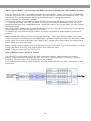
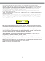
Input (LIN/RIN) Channel. EQ Block Scheme
The DS-CP25 in its input path, before the RMS Compressors section, make available to the user a
powerful 5 Band parametric Equalizer with each one of the 5 Filters selectable as Peaking or Shelving.
In addition, Hp and Lp filters up to 24dB/Oct slope, are available.
In the following block scheme, which shows the DS-CP25 overall structure, the EQ is represented by the
purple block.
14
HPF sub-menu - from this sub-menu, it is possible to set the Input Channels High Pass Filter (HPF),
preceding the bank of 5 Peaking/Shelving filters.
The following is an example of a HPF sub-menu screen with the filter set at 24dB Linkwitz/Riley on Channel
A/Left:
OutputA Left
HPF
-> 40.0 Hz Lnk/Ril 24dB
The filter’s parameters can be modified by use the “PM2” and “PM3” encoders for editing the Filter’s Low
Cut Frequency and the Filter’s Type and Order.
The Low Cut Frequency of the High Pass Filter can be edited using the “PM2” encoder and the Filter’s
Type and Order can be edited by using the “PM3” encoder.
“Low Cut Frequency” - the selectable frequencies range is from 20Hz to 20kHz in steps of 1/12 of an
Octave and can be adjusted by rotating the “PM2” encoder.
“High Pass Type and Order” - allows you to select the EQ’s High Pass Filter Shape and Order.
The available shapes and orders for the High Pass Filter, that are accessible by rotating the “PM3” encoder,
are listed below:
- No Cut-Off (High Pass Filter Bypassed)
- Butwrth 6dB (Butterworth Filter 6dB/Oct Slope)
- Butwrth 12dB (Butterworth Filter 12dB/Oct Slope)
- Lnk/Ril 12dB (Linkwitz/Riley Filter 12dB/Oct Slope)
- Bessel 12dB (Bessel Filter 12dB/Oct Slope)
- Butwrth 18dB (Butterworth Filter 18dB/Oct Slope)
- Butwrth 24dB (Butterworth Filter 24dB/Oct Slope)
- Lnk/Ril 24dB (Linkwitz/Riley Filter 24dB/Oct Slope)
- Bessel 24dB (Bessel Filter 24dB/Oct Slope)
Note1: Once the desired options have been selected using the 2 encoders, they are automatically saved as
current and stored in the DS-CP25 system status once leaving the page.
Note2: To exit this page, push the “ESC” button.
LPF sub-menu - from this sub-menu it is possible to set the Input Channels Low Pass Filter (LPF),
following the bank of 5 Peaking/Shelving filters.
The following is an example of a LPF sub-menu screen with the filter set at 24dB Linkwitz/Riley on Channel
A/Left:
OutputA Left
LPF
-> 12.0 kHz Lnk/Ril 24dB
The filter’s parameters can be modified by use the “PM2” and “PM3” encoders for editing the Filter’s High
Cut Frequency and the Filter’s Type and Order.
The High Cut Frequency of the Low Pass Filter can be edited using the “PM2” encoder and the Filter’s
Type and Order can be edited by using the “PM3” encoder.
“High Cut Frequency” - the selectable frequencies range is from 20Hz to 20kHz in steps of 1/24 of an
Octave and can be adjusted by rotating the “PM2” encoder.
“Low Pass Type and Order” - this page allows you to select the Eq’s Low Pass Filter Shape and Order.
15
The available shapes and orders for the Low Pass Filter that are accessible by rotating the “PM3” encoder
are listed below:
- No Cut-Off (Low Pass Filter Bypassed)
- Butwrth 6dB (Butterworth Filter 6dB/Oct Slope)
- Butwrth 12dB (Butterworth Filter 12dB/Oct Slope)
- Lnk/Ril 12dB (Linkwitz/Riley Filter 12dB/Oct Slope)
- Bessel 12dB (Bessel Filter 12dB/Oct Slope)
- Butwrth 18dB (Butterworth Filter 18dB/Oct Slope)
- Butwrth 24dB (Butterworth Filter 24dB/Oct Slope)
- Lnk/Ril 24dB (Linkwitz/Riley Filter 24dB/Oct Slope)
- Bessel 24dB (Bessel Filter 24dB/Oct Slope)
Note1: Once the desired options have been selected using the 2 encoders, they are automatically saved as
current and stored in the DS-CP25 system status once leaving the page.
Note2: To exit this page, push the “ESC” button.
EQ: [x] sub-menu - from this sub-menu it is possible to set the Input Channels 5 available Peaking or
Shelving Filters.
OutputA Left
EQ-X
1.00KHz BW1.05 0.0dB
The DS-CP25 allows the user to select either Peaking or Shelving Parameters and assign them
independently using the 5 available filters.
In order to select the filter’s type, it is necessary to have the filter’s GAIN=0.0dB, then using the “PM2”
encoder, rotate it “clockwise” in order to decide the Peaking filter’s Bandwidth, or “counter-clockwise” to
select the Shelving filter type (Low or High) and its order (1st or 2nd).
So, in order to define the filter type for the filter number 1 ( “x” = 1), it is necessary from the above screen,
to enter the filter’s editing page pressing the “ENTER” button, and the screen has to appear as follows:
OutputA Left
EQ-1
-> 1.00KHz BQ1.05 0.0dB
In this case, the filter’s GAIN=0.0dB, and being BW=1.05, the current filter selected is a Peaking type.
Now, rotating the “PM2” encoder clockwise, the parameter BW will range from 0.05 up to 3 for identifying a
bandwidth value for a Peaking filter.
If a Peaking filter is selected, then the Gain can be modified from 0.0dB and the BW will range between
0.05 and 3.
If the user wants to select a Shelving filter from the above setting, with the GAIN=0.0dB [if the GAIN is not
0.0dB, it is necessary to set it at 0.0dB using the “PM3” encoder], rotate the “PM2” counter-clockwise. Once
BW reaches the 0.05 value, at the next step of the “PM2” counter-clockwise rotation, the selection of the
Shelving filters will be entered.
16
Still rotating the “PM2” counter-clockwise, the Shelving filters and their order will be selectable in the
following sequence:
1. 1st Order Low Shelving = -6LoSh [on the screen]
2. 2nd Order Low Shelving = -12LoSh [on the screen]
3. 1st Order High Shelving = -6HiSh [on the screen]
4. 2nd Order High Shelving = -12HiSh [on the screen]
Once the desired Shelving filter is selected, the “PM3” can then be used to select the desired GAIN and
when the GAIN is set at a value different from 0.0dB, then the filter type cannot be changed until this GAIN
is returned to 0.0dB.
Peaking Filter - As an example, if we want to set a Peaking filter within EQ-1, then the BW has to be set at
a desired value of say 1.00 using the “PM2” encoder, the GAIN at say +3dB using the “PM3” Encoder and
the center Frequency at say 1.00KHz with the “NAV/PM1” encoder.
The EQ sub-menu screen will show the following:
OutputA Left
EQ-1
-> 1.00KHz BW1.00 +3.0dB
Once in the Peaking Filter’s edit screen, all the filter’s parameters can be modified using the “NAV/PM1”,
“PM2” and “PM3” encoders for editing the Filter’s Center Frequency, Bandwidth BW and Gain.
The Center Frequency of the Parametric Filter can be edited using the “NAV/PM1” encoder, the BW the
“PM2” encoder and the Gain the “PM3” encoder.
“Center Frequency” - the selectable frequencies range is from 20Hz to 20kHz in steps of 1/12 of an
Octave and can be adjusted by rotating the “NAV/PM1” encoder.
“Bandwidth BW” - the selectable BW range is from 0.05 Octave to 3 Octave in steps of 0.05 Octave and
can be adjusted by rotating the “PM2” encoder.
“Gain” - the selectable Gain range is from -15dB to +15dB in steps of 0.5dB and can be adjusted by
rotating the “PM3” encoder.
Low Shelving Filter - As an example, if we want to set a Low Shelving filter within EQ-1, then the “PM2”
encoder has to be rotated counter-clockwise until the desired Low Shelving filter say -6LoSh appears on
the screen, the GAIN at say +3.0dB using the “PM3” encoder and the High Cut Frequency at say 1.00KHz
with the “NAV/PM1” encoder.
The EQ sub-menu screen will show the following:
OutputA Left
EQ-1
-> 1.00KHz BW1.00 +3.0dB
Note: Once the desired Low Shelving filter is selected, the “PM3” can then be used to select the desired
GAIN and when the GAIN is set at a value different from 0.0dB, then the filter type cannot be changed until
this GAIN is returned to 0.0dB.
17
Once in the Low Shelving Filter’s edit screen, all the filter’s parameters can be modified using the
“NAV/PM1”, “PM2” and “PM3” encoders for editing the Filter’s High Cut Frequency, Filter’s Order and Gain.
The Hi Cut Frequency of the Low Shelving Filter can be edited using the “NAV/PM1” encoder, the Filter’s
Order can be adjusted by the “PM2” encoder and the Gain the “PM3” encoder:
“Hi Cut Frequency” - the selectable frequencies range is from 20Hz to 20kHz in steps of 1/12 of an
Octave and can be adjusted by rotating the “NAV/PM1” encoder.
“Low Shelving Order” - the selectable Low Shelving Filter’s range can be selected between the 1st
(Lo-1st.) and the 2nd (Lo-2nd.) one.
“Gain” - the selectable range of the Gain is from -15dB to +15dB in steps of 0.5dB and can be adjusted by
rotating the “PM3” encoder.
High Shelving Filter - As an example if we want to set a High Shelving filter within EQ-1 then the “PM2”
encoder has to be rotated counter-clockwise until the desired High Shelving filter say -6HiSh appears on
the screen, the GAIN at say +3dB using the “PM3” encoder and the Low Cut Frequency at say 1000KHz
with the “NAV/PM1” encoder.
OutputA Left
EQ-1
-> 1.00KHz -6HiSh +3.0dB
Note: Once the desired High Shelving filter is selected, the “PM3” can then be used to select the desired
GAIN and when the GAIN is set at a value different from 0.0dB, then the filter type cannot be changed until
this GAIN is returned to 0.0dB.
Once in the High Shelving Filter’s edit screen, all the filter’s parameters can be modified using the
“NAV/PM1”, “PM2” and “PM3” encoders for editing the Filter’s Low Cut Frequency, Filter’s Order and Gain.
The Lo Cut Frequency of the High Shelving Filter can be edited using the “NAV/PM1” encoder, the Filter’s
Order can be adjusted by the “PM2” encoder and the Gain the “PM3” encoder:
“Lo Cut Frequency” - the selectable frequencies range is from 20Hz to 20kHz in steps of 1/12 of an
Octave and can be adjusted by rotating the “NAV/PM1” encoder.
“High Shelving Order” - the selectable High Shelving Filter’s range can be selected between the 1st
(Lo-1st.) and the 2nd (Lo-2nd.) one.
“Gain” - the selectable range of the Gain is from -15dB to +15dB in steps of 0.5dB and can be adjusted by
rotating the “PM3” encoder.
Note1: Once the desired options have been selected using the 3 encoders, they are automatically saved as
current and stored in the DS-CP25 system status once leaving the page.
Note2: To exit this page, push the “ESC” button.
18
• Menu “AGC and Output Limiter” Editing [access by pushing “Lim/Comp - Edit/Bypass” buttons]
From the “Default Screen”, it is possible to access the “AGC and Output Limiter” menu by pressing the
“Lim/Comp - Edit/Bypass” buttons at the bottom of the LOUT or ROUT LED bars. Once pressed, the related
blue “EDIT” LED will turn ON. The Sub-Menus pages can now be scrolled through by rotating clockwise
and counter-clockwise the “NAV/PM1” encoder.
For parameter editing, it is necessary to press “ENTER” and an arrow will appear on the left of the screen
“->”. Then use the “PM2” and “PM3” encoders for selecting and setting the Parameter values. On some
parameters that have three independent values, you will also need to use the “NAV/PM1” encoder, for
example, for the filter’s parameter setting.
The “Lim/Comp - Edit/Bypass” buttons have also, the AGC BYPASS function. If pressed for more than 3
seconds, the AGC of the related Channel will be BYPASSED and the LED will turn RED.
To ACTIVATE the AGC again, from the BYPASSED condition, press the “Lim/Comp - Edit/Bypass” button
again for more than 3 seconds.
Note: All parameter editing can be done using the “NAV/PM1”, “PM2”, and “PM3” encoders and the current
shown value of the selected option is AUTOMATICALLY loaded during the encoders’ use, and stored as the
current value once leaving the page.
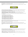
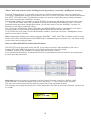
AGC and LIM (LOUT/ROUT) location Block Scheme
The DS-CP25 on its input path, before the EQ, Comp and Lim section, make available to the user a
powerful AGC with RMS Peak detection, and a Peak Limiter before the final Output.
In addition, a Delay is also available, as well as Gain and Polarity controls.
In the following block scheme, showing the DS-CP25 overall structure, the AGC and Lim are represented
by the purple and pink blocks.
Gain page - from this screen it is possible to set the Output Channels Level from -12dB to +6dB.
Press “ENTER”, an arrow will appear on the left of the screen “->”, then use the “PM3” encoder.
The value set on this screen will only affect the input level of the selectable Channel.
The following is an example screen for the “Gain” page where the Gain of the Output Channel 1 [Left] is set
to +0.0dB
OutputA Left
-> Gain = + 0.0dB
19
Gain
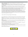
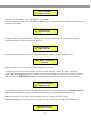
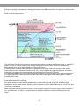
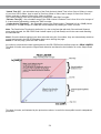
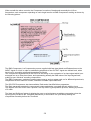
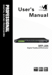
Before proceeding to illustrating the editing and setting of the AGC parameters, it is good to remember how
an AGC (Automatic Gain Controller) works.
Refer to the following picture:
The AGC is an Expansion/Compression process applied with slow Attack and Release times, to the INPUT
signal of a Unit, in order to maintain the average amplitude of the OUTPUT signal at a defined level,
independently from the average amplitude of the input sources.
For this purpose, the AGC has to be able to expand the input signal, where the average of the related
output signal is below a defined Threshold (Exp Thr), and to maintain the expanded signal at a constant
expansion level when the averaged signal is beyond a defined Threshold (Thr Hold).
The AGC implemented in the DS-CP25 acts on the evaluation of an input signal which is an averaged one
on a 50ms time frame, and represents the RMS Value of the input signal itself, making a more “Musical”
sounding AGC action.
If the output signal of the AGC process will exceed a defined Threshold (Cmp Thr), becoming too loud, a
compression process is occurring.
The speed and the amount of the Expansion can be defined through the “Exp Time” and “Exp Ratio”
parameters, as the speed and the amount of the Compression can be defined through the “Cmp Time” and
“Cmp Ratio” parameters.
When the Signal coming out from the AGC process (Output), applied to the AGC input, is above the “Exp
Thr” and below the “Thr Hold”, it is expanded up to the max expansion coefficient defined by the “Exp
Ratio”.
20
When the Signal coming out of the AGC process (Output), applied to the AGC input, is above the “Cmp
Thr”, it is compressed up to the minimum compression coefficient defined by the “Cmp Ratio”.
When the AGC output is comprised within the “Thr Hold” and the “Cmp Thr” Thresholds, no further
expansion or compression actions will be taken and the expansion/compression coefficient, will be
maintained with its current value.
Particularly, if the averaged AGC output level is “entering” the signal “hold” area coming from the expansion
area, then the Coefficient computed by the AGC for multiplying the input level in order to get the proper
output signal, will be higher than one (if the “Exp Ratio” will be set at 1:2), so as the coefficient will be lower
than one (if the “Cm Ratio” will be set between 2:1 and 16:1) if the averaged AGC output level is “entering”
the signal “hold” area coming from the compression area.
AGC Bypass Page - from this screen it is possible to set the AGC On or OFF, so to activate it or not
without resetting the all parameters. Press “ENTER”, an arrow will appear on the left of the screen “->” then
use the “PM3” encoder.
The following is an example screen for the “AGC Bypass” page where the AGC is set Active:
OutputA Left
AGC
-> AGC Bypass = Off
AGC Exp Time Page - from this screen it is possible to set the AGC Expansion time from 0.057 seconds
up to 14.4 seconds. Press “ENTER”, an arrow will appear on the left of the screen “->” then use the “PM3”
encoder.
The following is an example screen for the “AGC Exp Time” page where the Expansion Time is set to 1.5s:
OutputA Left
AGC
-> AGC Exp Time = 1.500S
AGC Cmp Time Page - from this screen it is possible to set the AGC Compression time from 0.014
seconds up to 6 seconds. Press “ENTER”, an arrow will appear on the left of the screen “->” then use the
“PM3” encoder.
The following is an example screen for the “AGC Cmp Time” page where the Compression Time is set to
0.5s:
OutputA Left
AGC
-> AGC Cmp Time = 0.500S
AGC Exp Thr Page - from this screen it is possible to set the AGC Expansion Threshold from -50dBu up to
0dBu. Press “ENTER”, an arrow will appear on the left of the screen “->” then use the “PM3” encoder.
The following is an example screen for the “AGC Exp Thr” page where the Expansion Threshold is set to
-50dBu:
OutputA Left
AGC
-> AGC Exp Thr = -50dBu
21
AGC Cmp Thr page - from this screen, it is possible to set the AGC Compression Threshold from -10dBu
up to +20dBu. Press “ENTER”, an arrow will appear on the left of the screen “->” then use the “PM3”
encoder.
The following is an example screen for the “AGC Cmp Thr” page where the Compression Threshold is set
to +3dBu:
OutputA Left
AGC
-> AGC CmpThr = +3dBu
AGC Thr Hold page - from this screen, it is possible to set the AGC Threshold of the AGC Signal “Hold”
area, from -30dBu up to +20dBu. Press “ENTER”, an arrow will appear on the left of the screen “->” then
use the “PM3” encoder.
The following is an example screen for the “AGC Thr Hold” page where the Threshold of the Signal “Hold”
area is set to -40dBu:
OutputA Left
AGC
-> AGC Thr Hold = -40dBu
AGC Exp Ratio page - from this screen, it is possible to set the AGC Expansion Ratio from 1, up to 2.
Press “ENTER”, an arrow will appear on the left of the screen “->” then use the “PM3” encoder.
When the Expansion Ratio is set to 1, actually there is no possibility to expand the signal, meaning that the
signal amplitude can be multiplied for a coefficient not higher than 1.
If the Expansion Ratio is set to 2, the signal can be expanded up to a max amplitude that is twice the
original one.
The following is an example screen for the “AGC Exp Ratio” page where the Expansion Ratio is set to 2
and the Signal can be expanded up to double of its original amplitude:
OutputA Left
AGC
-> AGC Exp Rto = 1:2
AGC Cmp Ratio page - from this screen, it is possible to set the AGC Compression Ratio from 1 up to 16.
Press “ENTER”, an arrow will appear on the left of the screen “->” then use the “PM3” encoder.
When the Compression Ratio is set to 1, actually there is no possibility to compress the signal, meaning
that the signal amplitude can be multiplied for a coefficient not smaller than 1.
If the Compression Ratio is set to 2 or more, the signal can be expanded up to a min amplitude that is
depending from the ratio and can reach 1/16th of the original signal amplitude.
The following is an example screen for the “AGC Cmp Ratio” page where the Compression Ratio is set to 4
and the Signal can be compressed up to 1/4th of its original amplitude:
OutputA Left
AGC
-> AGC Cmp Rto = 4:1
22
Delay page - from this page, it is possible to set the Output Channels Delay Time from 000.0000ms up to
848.9984mS, by steps of 1mS or 20.8uS.
To set the Delay time, press “ENTER”, an arrow will appear on the left of the screen “->” then use the “PM2”
encoder to set the Delay Time in steps of 1mS and the “PM3”, for setting the “fine” Delay Time in steps of
20.8 microseconds.
The following is an example screen for the “Delay” page where the Delay time of Output Channel 1 is set to
160.1872mS:
OutputA Left
Delay
-> Delay = 160.1872mS
Polarity page - from this page, it is possible to set the Output Channels Polarity, by using the “PM3”
encoder.
The polarity can be “Normal” or “Inverted”.
The following is an example of a “Polarity” screen where the Polarity of Output Channel is set to “Normal”:
OutputA Left
Polarity
-> Polarity = Normal
Peak Limiter sub-menu - from this page, it is possible to set the Output Channels Peak Limiter.
The following is an example screen for the Peak Limiter page where the Attack Time of the Peak Limiter is
set at 5ms, the Release Time is set at 0.2Sec and the Peak Limiter Active Threshold is set at +15dB:
OutputA Left
Limiter
A: 5ms R: 0.2s +15.0dB
Upon pushing “ENTER”, the Peak Limiter’s parameters can be modified using the “NAV/PM1”, “PM2” and
“PM3” encoders for editing the Peak Limiter’s Attack Time [A], Release Time [R] and Active Threshold.
Once pushing “ENTER”, the above screen will change as follows:
OutputA Left
Limiter
-> A: 5ms R: 0.2s +15.0dB
The Attack Time [A] can be edited using the “NAV/PM1” encoder, the Release Time [R] using the “PM2”
Encoder and the Peak Limiter Active Threshold using the “PM3” encoder.
23
“Attack Time [A]” - the selectable range of the Peak Limiter’s Attack Time is from 5ms to 200ms, in steps
of 1ms from 5ms to 20ms, then in steps of 5ms from 20ms to 30ms, then in steps of 10ms from 30ms to
100ms, and then in steps of 20ms from 100ms to 200ms.
The Limiter’s Attack Time can be adjusted by rotating the “NAV/PM1” encoder.
“Release Time [R]” - the selectable range of the Peak Limiter’s Release Time is from 0.1s to 3s in steps of
0.1s and can be adjusted by rotating the “PM2” encoder.
“Limiter Active Threshold” - the selectable range of the Peak Limiter’s Threshold is from +20dB (Limiter
not active) to -10.0dB in steps of 0.2dB and can be adjusted by rotating the “PM3” encoder.
Note: The Peak limiter Threshold is defined in Vp, due to the fact that with both, Sinusoid and Squared
wave testing signals, the DS-CP25 Peak Limited output Vp (Peak-Peak) Level is the same and matching
the selected one.
Note1: Once the desired options have been selected using the 3 encoders, they are automatically saved as
current and stored in the DS-CP25 system status once leaving the page.
Note2: to exit this page, push the “ESC” button.
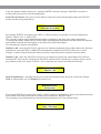
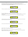
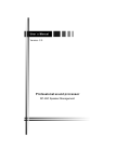
It’s useful to note that the Limiter implemented on the DS-CP25 before the final output is a PEAK LIMITER.
This kind of Limiter acts upon the Signal Peak detection and therefore the limitation is on the Output Peak
value.
This kind of Limiter, as illustrated by the picture here above, is useful for the amplifier’s and Loudspeakers’
protection.
24
Ÿ
Menu “RMS Compressors” Editing [Access by pushing the “Lim/Comp - Edit/Bypass” buttons]
From the “Default Screen”, it is possible to access the “RMS Compressors” menu by pressing the
“Lim/Comp - Edit/Bypass” buttons at the bottom of the 3xLCOMP or 3xRCOMP LED bars. Once pressed,
the related blue “EDIT” LED will turn ON.
The Sub-Menus pages can now be scrolled through by rotating clockwise and counter-clockwise, the
“NAV/PM1” encoder.
For parameter editing, it is necessary to press “ENTER” and an arrow will appear on the left of the screen
“->”. Use the “PM2” and “PM3” encoders for selecting and setting the parameter values. On some
parameters that have three independent values, you will also need to use the “NAV/PM1” encoder, for
example for the filter’s parameter setting.
The “Lim/Comp - Edit/Bypass” buttons also have the RMS COMPRESSOR BYPASS function. If pressed for
more than 3 seconds, the RMS COMPRESSOR of the related Channel will be BYPASSED and the LED will
turn RED.
To ACTIVATE the RMS COMPRESSOR again, from the BYPASSED condition, press the “Lim/Comp Edit/Bypass” button again for more than 3 seconds.
Note: All parameter editing can be done using the “NAV/PM1”, “PM2”, and “PM3” encoders and the current
shown value of the selected option is AUTOMATICALLY loaded during the encoders’ use and stored as the
current value once leaving the page.
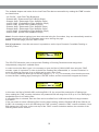
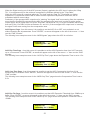
RMS Compressors (LCOMP/RCOMP) Block Scheme
The DS-CP25 processing core is based on 3 powerful RMS compressors on each channel, that can be
applied to 3 sub bands definable by the user.
The DS-CP25 is very flexible allowing you to set the compression process as a 3 band, 2 band or Mono
band.
On its input path, after the AGC and EQ, and before the final Peak Limiter, the DS-CP25 makes available to
the user, a powerful “up to 3 band” RMS Compressor, which is editable independently on each one of its 3
RMS “Sub” Compressors (if set as the 3 bands mode) or 2 of them (if set as the 2 bands mode) or just one
(when in Mono band mode).
In addition to a control for setting the Compressor Mode (2, 3 or Mono band), there is a control for setting
the crossover frequencies.
In the following block scheme, showing the DS-CP25 overall structure, the RMS Compressor section is
represented by the purple block.
25
The DS-CP25 multi band compressor, can operate as 3 bands, 2 bands or Mono band compressor unit.
Because of that, within the Compressors Menu there are up to 3 common control pages, allowing the user
to set the number of bands for the compressor and, independently from this selection, to set the X-Over
frequencies for the definition of the 3 or 2 bands.
The setting of any one of these common controls is replicated on each editing Menu of each of the active
bands, independently from where (within what band's editing Menu) the controls have been set.
When the DS-CP25 is set as 3 bands compressor, each single band compressor can be accessed for an
independent editing session by just entering each one of the 3 compressors’ editing pages, by pressing the
“Lim/Comp - Edit/Bypass” button set at the bottom of the first, second and third LED row, at the left side of
the LCOMP/RCOMP labels.
If the DS-CP25 is set for a number of bands less than 3, then accordingly with the bands number, only the
first or second button will allow the access to the single or to the 2 bands.
Band Mode Page - from this page, it is possible to set the DS-CP25 in terms of sub-bands process by an
independent RMS compressor.
To set the Band Mode, press “ENTER”. An arrow will appear on the left of the screen “->”, then use the
“PM3” encoder to set the desired number of Bands.
If selecting 3, the DS-CP25 will work as 3 band stereo compressor and all three bands will be processed by
an independent RMS compressor, which parameters can be edited by 3 different menus, accessed through
the “Lim/Comp - Edit/Bypass” buttons at the bottom of the LCOMP/RCOMP LED bars.
If selecting 2, the number of bands will be 2, and the editing menu closer to the LCOMP/RCOMP labels will
be not accessible.
If selecting 1, the DS-CP25 will be a powerful MONO BAND compressor. The only accessible Editing Menu
for setting the RMS compressor parameters will be the one accessed by the buttons “Lim/Comp Edit/Bypass” buttons at the bottom of the LCOMP/RCOMP LED bars located at the most far left position
from the LCOMP/RCOMP labels.
The following is an example screen for the “Band Mode” page where the Band Mode is set as 3:
OutputA Left
Cmp
-> Band Mode = 3 Band
26
CrossOver 1 page - when the DS-CP25 is set in Mono Mode, “1 band”, this page is not available and the
RMS single compressor will act on the overall input band.
When the DS-CP25 is set as “2 band” compressor, then from this page it is possible to set the Cross Over
frequency, separating the 2 bands, dividing the full one.
On each of the 2 bands, below and above the selected frequency, 2 independent RMS compressors will
act.
When the DS-CP25 is set as “3 band” compressor, then from this page it is possible to set the Cross Over
frequency, separating the 2 lower bands of the 3, dividing the full one .
On each of the 3 bands, 3 independent RMS compressors will act.
To set the “band 1” (Low) and the “band 2” (High) Cross Over Frequency, press “ENTER”. An arrow will
appear on the left of the screen “->”, then use the “PM2” encoder to set the desired number of bands.
The range of the selectable frequencies is from 20Hz up to 20kHz by steps of 1/12th of octave.
Care must be taken by the user that when selecting the “3 band” mode, the CrossOver 1 selected
frequency does not overlap the one selected on the CrossOver 2 editing page.
The following is an example screen for the “CrossOver 1” page where the Cross Over frequency is set to
250Hz:
OutputA Left CrossOver1
->
250 Hz
CrossOver 2 page - when the DS-CP25 is set in Mono Mode, “1 band”, or in “2 band” Mode, this page is
not available and the RMS single compressor (1 band mode selection) or the 2 RMS compressors (2 band
mode selection), will act on the overall or on the 2 selected input bands.
When the DS-CP25 is set as “3 band” compressor, then from this page it is possible to set the Cross Over
frequency, separating the 2 higher bands of the 3, dividing the full one.
On each of the 3 bands, 3 independent RMS compressors will act.
To set the “band 2” (Mid) and the “band 3” (High) Cross Over Frequency, press “ENTER”. An arrow will
appear on the left of the screen “->”, then use the “PM2” encoder to set the desired number of bands.
The range of the selectable frequencies is going from 20Hz up to 20kHz by steps of 1/12th of octave.
Care must be taken by the user that when selecting the “3 band” mode, the CrossOver 2 selected
frequency does not overlap the one selected on the CrossOver 1 editing page.
The following is an example screen for the “CrossOver 2” page where the Cross Over frequency is set to
2500Hz:
OutputA Left CrossOver2
->
2500 Hz
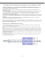
27
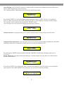
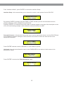
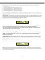
When set with the above controls, the Compressor’s number of bands and eventually the X-Over
frequencies, each compressor operating on each single band is an RMS Compressor working as shown by
the following picture:
The RMS Compressor is a Compression process, applied with fast slow Attack and Release times to the
INPUT signal of a Unit, in order to maintain the amplitude of the OUTPUT signal at a defined level, when
input level is exceeding a defined intervention Threshold.
The Compressors implemented in the DS-CP25 are acting on the evaluation of an input signal which is an
averaged one on a 50ms time frame, and representing actually the RMS value of the input signal itself,
making a more “Musical” sounding compression.
The RMS Compressor, maintains constant output energy and not output peak, so for different inputs levels,
independent of their harmonic content, maintains constant output RMS level.
The DS-CP25 Compressor also has available, Ratio and a Hard/Soft Knee parameters.
The Ratio parameter controls the compressed output maintaining a constant dB ratio with the input.
This feature in the DS-CP25 uses a precise Look Up Table Log Computation process, allowing a precision
of 0.1dBu.
The Hard and Soft knee feature is allowing the user to select between a sudden compression when the
input signal is just above the Threshold (Hard Knee) or a smoother one {Soft Knee} starting the
compression smoothly before the Threshold.
28
Attack Time page - from this page, it is possible to set the Attack Time parameters of the RMS
Compressor.
Upon pushing “ENTER”, the RMS Compressor’s Attack Time editing page can be entered and using the
“PM3” encoder, the “Attack Time” parameter can be set.
OutputA Left
Cmp1
-> Attack Time = 50ms
“Attack Time” - the selectable range of the RMS Compressor’s Attack Time is from 5ms to 200ms, in
steps of 1ms from 5ms to 20ms, then in steps of 5ms from 20ms to 30ms, then in steps of 10ms from 30ms
to 100ms, and then in steps of 20ms, from 100ms to 200ms.
Release Time page - from this page, it is possible to set the Release Time parameters of the RMS
Compressor.
Upon pushing “ENTER”, the RMS Compressor’s Release Time editing page can be entered, and using the
“PM3” encoder, the “Release Time” parameter can be set.
OutputA Left
Cmp1
-> Release Time = 250ms
“Release Time” - the selectable range of the RMS Compressor’s Release Time is from 0.1s to 3s in steps
of 0.1s.
Threshold page - from this page, it is possible to set the Threshold parameters of the RMS Compressor.
Upon pushing “ENTER”, the RMS Compressor’s Threshold editing page can be entered and using the
“PM3” encoder, the “Threshold” parameter can be set.
OutputA Left
Cmp1
-> Threshold = 50ms
“Threshold” - the selectable range of the RMS Compressor’s Threshold is from +20dBu (OFF) to -5dBu in
steps of 0.2dBu.
Ratio page - from this page, it is possible to set the Ratio parameters of the RMS Compressor.
Upon pushing “ENTER”, the RMS Compressor’s Ratio editing page can be entered and using the “PM3”
encoder, the “Ratio” parameter can be set.
OutputA Left
-> Ratio [I/O] = 4:1
Cmp1
“Ratio” - the selectable range of the RMS Compressor’s Ratio is from 1:1 (Off) up to 32:1 (Lim) in steps of
0.2.
29
Ratio page - from this page, it is possible to set the “Knee” type of the RMS Compressor.
Upon pushing “ENTER”, the RMS Compressor's Knee editing page can be entered and using the “PM3”
encoder, the “Ratio” parameter can be set.
OutputA Left
CMP1
-> Knee Soft-Hard = 0%
“Hard/Soft Knee” - the selectable range of the RMS Compressor’s Knee type is from 0% (Hard) up to
100% (Soft) by steps of 1.
Drive page - from this page, it is possible to set the “Drive” parameter of the RMS Compressor, which is
useful for modifying the level of the Compressor input signal.
Upon pushing “ENTER”, the RMS Compressor’s Knee editing page can be entered and using the “PM3”
encoder, the “Ratio” parameter can be set.
OutputA Left
-> Drive = +0.0dB
Cmp1
“Drive” - the selectable range of the RMS Compressor’s Drive is from -12dB up to +6dB by steps of 0.5dB.
OutGain page - from this page, it is possible to set the “Output Level” of the RMS Compressor.
Upon pushing “ENTER”, the RMS Compressor’s Knee editing page can be entered and using the “PM3”
encoder, the “Output Level” parameter can be set.
OutputA Left
-> OutGain = +0.0%
Cmp1
“OutGain” - the selectable range of the RMS Compressor’s Drive is from -12dB up to +6dB by steps of
0.5dB.
30
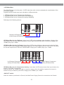
• LED Meter Bars
The DS-CP25 has on its front panel, 10 LED meter bars, able to show constantly the overall status of the
processed signals.
Logically, the LED meter bars can be divided in 2 different blocks:
1. LED Meter Bars for the Clip/lnput level displaying
2. LED Meter Bars for the Limiter/Output level displaying
3. LED Meter Bars for the Compressors activity displaying
Referring to the following pictures:
L IN
L OUT
R IN
R OUT
Clip/Input LED Meter Bars
Limiter/Output LED Meter Bars
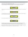
LED Meter Bars for the Clip/Input - these bars of LED meters indicates, when turned on, clipping of the
input signal, with the other LEDs showing the current input level BEFORE ANY PROCESS, ranging from
+20dBu (Clip) up to -20dBu.
LED Meter Bars for the Lim/Output: these bars of LED meters indicates, when turned on, that the Peak
Limiter is active and limiting the output signal, clipping of the output signal, with the other LEDs is showing
the current output level AFTER ALL PROCESSES, ranging from +20dBu (Clip) up to -15dBu.
LCOMP
Cmp1
Cmp2
Cmp3
R COMP
Cmp1
Lch
Cmp2
Cmp3
Rch
Right Channel Compressor
Activity LED Meter Bars
Left Channel Compressor
Activity LED Meter Bars
LED Meter Bars for the Compressors Activity - these bars of LED meters shows from top to bottom, the
activity of the RMS Compressors.
When not active, the +20dBu LED will be turned on orange, when the activity is present, its amount is
shown from top to bottom by the LEDs, ranging from +20dBu up to -10dBu.
•GND LIFT switch
When the switch is positioned on Ground, the Main Power Supply Ground is connected to the Chassis.
31
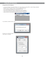
Using the PC Interface
Using the DS-CP25 Software.
l
l
l
l
l
l
Load the Software “SetupDS-CP25V1.0.0” either with the included CD or via the Galaxy Website.
Double click on “Setup”, choose “Run” the software will load.
Go to programs and double click on DS-CP25V1.0.0
Connect the SDS-CP25 with the USB cable to your computer.
Turn on the DS-CP25, the driver software will load automatically.
When the driver has finished loading, click once on “connect”.
If you want to continue select “Yes”
Choose your connection type.
Then Click on Connect.
32
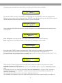
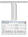
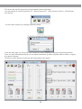
The software will look for active devices and show them in a list.
To edit Double click on the desired device in the ID list.
The Main Page will load.
33
The device will also be locked out from front panel control at this point.
You may choose to “Load Preset from PC”, “Save Preset to PC”, “Store Preset to Device”, “Read Preset
from Device”
You can name a device by selecting edit device name.
From the main page you can choose the section you want to adjust by clicking on the associated block.
Once you have accessed the block you can adjust parameters by either using the sliders, arrows, or typing
the values in directly.
Select the volume block to access the gain and polarity of the inputs.
34
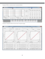
Select the PEQ or crossover block to access the filters.
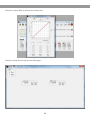
Select the Compressor Block to access the Compressor page.
35
Select the Limiter Block to access the Limiter page.
Select the Delay block to access the delay page.
36
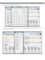
Select the AGC Block to access the AGC page.
You can copy parameters between channels by selecting the copy channel block and then selecting the source
parameters and the destination.
37
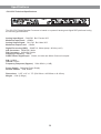
Specifications
• DS-CP25 Technical Specifications
Made in China
The DS-CP25 Digital Speaker Processor is based on a powerful analog and digital DSP platforms having
the following specifications:
Analog Input Signal: ChA/ChB Bal. Female XLR
Maximum Input Level: +20dBu
Analog Output Signal: Ch1/Ch2 Bal. Male XLR
Maximum Output Level: +20dBu
Digital Processing (DSP): SAM3716, 24bits (data) x 96 bits (coeff.)
A/D Converters: AKM5392, 24bits
D/A Converters: AKM4396, 24bits
Sampling Frequency: 48kHz
S/PDIF Stereo Digital Input: 32kHz, 44.1kHz and 48kHz Sources Accepted
S/N: 110dBA
THD+N: 0.005%
Frequency Response (Bypass): 20Hz-20kHz (+-1dB)
Power Supply: Switching Power Supply
Remote Control: USB, RS485
Dimensions: 9.25" x 19" x 1.75" (234.95mm x 482.60mm x 44.45mm)
Weight: 6.3lb (2.86kgs)
38
THREE YEAR LIMITED WARRANTY
WARRANTY Information can be viewed online at
http://www.galaxyaudio.com/warranty.php
DS-CP25
Specifications in this manual are subject to change without notice.
For the most up to date manual and information
visit www.galaxyaudio.com.
1-800-369-7768
www.galaxyaudio.com
© Copyright Galaxy Audio 2014
Printed in China
V02062014