1
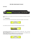
ACHAT DSP24 Digital Speaker Processor ENGLISH USER’S MANUAL Introduction Thank you very much for expressing your confidence in our products by purchasing the ACHAT DSP24, our high-quality Digital Speaker Processor, designed specifically for both live and studio applications. Please read the manual carefully and keep it for future reference. Important Safety Instructions For your own safety you must read this section in full first! Intended use This manual explains the intended use of the device. Using it in any other way invalidates the warranty and you risk a lifethreatening electric shock. Warning: This symbol, wherever it appears, alerts you to important operating and maintenance instructions in the accompanying literature. So read the manual. Risk of electrical shock! • Connect the device only to a properly wired and earthed electrical wall socket providing a mains voltage of 230 V~/ 50 Hz. • NEVER operate the device if the device itself, the power plug, or the power cord is damaged. • NEVER submerse the device in water or any other fluid. Wipe it only with a slightly damp cloth. • NEVER expose the device to rain or moisture and never use it in a damp or wet environment. This device was developed for indoor use only. Do not use it outdoors. • Ensure that the power cord does not become wet during operation. 2 • You must NEVER open the housing of the device or try to repair it. There are no user serviceable parts inside. Warranty will become void if you open the housing and you face the risk of electric shock. • Do not place objects containing fluids, e.g. flower vases or beer bottles, on or near the device. • Notice regarding power disconnection: To disconnect the device from the power source the power plug must be removed from the power socket. For this reason the device must be placed in a position where a constant unobstructed access to the power socket is assured, thus in an emergency situation you are able to immediately pull out the power plug. To eliminate the risk of fire you must completely disconnect the power plug from the power socket when the device is not in use. • Always grasp the power cord by the plug. Do not pull on the cord itself and never touch the power cord with wet hands as this could result in a short circuit or an electrical shock. Do not place the device, speaker cabinets or anything else on the power cord and make sure that it does not become clamped. Place the power cord in a position where it can not be trod on. A damaged power cord can cause a fire or an electrical shock. Check the power cord from time to time. Should it become damaged contact our customer service centre to have it replaced. • Never manipulate the power cord or the plug. If a power cord is provided with an earth lead, this is mandatory to ensure safe operation! Risk of fire! • NEVER leave the device unattended while it is switched on. • Never cover any ventilation slots of the device while it is switched on. Avoid placing this device in locations that provide insufficient ventilation or hot locations and do not ACHAT DSP24 • OWNER’S MANUAL place the device in direct sunlight or under strong artificial light sources. Otherwise, it may overheat and become irreparably damaged. • Do not operate or store the device in hot locations or near heat sources like stoves, radiators, power amplifiers, or the like. • Do not place any open sources of fire, like candles, on the device. • When a thunderstorm with the risk of lightening threatens disconnect the device from the mains power. Risk of personal injury! • This appliance is not intended for use by individuals (including children) with restricted physical, physiological or intellectual abilities or deficiencies in experience and/ or knowledge unless they are supervised by a person responsible for their safety or receive from this person instruction in how the appliance is to be used. • Keep the power cord and device away from children, as they often underestimate the dangers of electrical equipment. • Ensure a safe location for the device. • Do not operate the device if it has sustained a fall or is damaged. Arrange for the device to be checked and/or repaired by qualified technicians. Installation • Select a location with sufficient circulation of air. Permanent overheating can damage the device. • NEVER operate the unit under the following conditions: > In places subject to vibrations or bumps. > In places with a temperature of over 40 °C or less than 2 °C. > In places subject to excessive dryness or humidity (ideal conditions are between 35% and 80%). This unit is designed to be fitted into a 19” rack. Secure the device with screws to the rack. ACHAT DSP24 • OWNER’S MANUAL When installing into a 19” rack please ensure that warm air can escape from the rack and that there is adequate distance between the individual devices. The rear wall of the rack should be opened when operating the devices. Cleaning and Maintenance Never immerse the device into water or any other liquid! Never let any liquid get into the housing. This would damage the device and/or cause a short circuit. Clean the surface of the housing with a damp cloth. Never use cleaning agents that contain alcohol, petrol, solvents, or any aggressive substance. Do not use chemical fibre cloth to wipe the cover to avoid the fading of the painting. Disposal For the transport and protective packaging, environmentally friendly materials have been chosen that can be supplied to normal recycling. Ensure that plastic bags, packaging, etc. are properly disposed of. Do not just dispose of these materials with your normal household waste, but make sure that they are collected for recycling. Please follow the notes and markings on the packaging. This product is subject to the European Waste Electrical and Electronic Equipment Directive (WEEE) in its currently valid version. Do not dispose of your old device with your normal household waste. Dispose of this product through an approved waste disposal firm or through your local waste facility. Comply with the rules and regulations that apply in your country. If in doubt, consult your local waste disposal facility. 3 Described below are the functions of the front panel control buttons and encoders for DSP24. B allow the user to enter the editing menus of the processor’s input channels. Buttons 1, 2, 3, and 4 allow the user to enter the editing menus of the processor’s output channels. Buttons A and B as well as the 1, 2, 3, and 4 buttons have double functions dependent on the push and hold time. Getting started As soon as the unit is turned ON the device model name will appear in the display: After the initialization, the unit will show the name of the previously selected program on the LCD prior to the unit being turned off. Encoders and ENTER, ESC buttons The DSP24 is equipped with 3 relative encoders, “NAV/PM1”, “PM2” and “PM3”. These encoders allow you to navigate the user interface and edit sections of the processor. They allow the user to navigate within the screen for the selection of submenus, pages and parameters and to select the values to be assigned during the editing operations. The “ENTER” and “ESC” buttons allow the user to confirm or NOT confirm the operations performed by the encoders. UTILITY, A/B and 1/2/3/4 buttons The UTILITY button allows the user to enter the sub-menus and to set the general characteristics of the processor. Buttons A and 4 When buttons A and B are pushed and held for more than one second, input channels A or B are either muted or un-muted. The red LED will illuminate when the channel is muted. When the “MUTE” LED is off, then the related input channel is un-muted. A brief push of the A and B buttons enters the editing mode for the input channels (see later for the input channel editing details). The blue “EDIT” LED will now be on. When the 1, 2, 3, and 4 buttons are pushed and held for more than one second the output channels 1, 2, 3, and 4 are either muted or un-muted. The red LED will illuminate when the channel is muted. When the “MUTE” LED is off, then the related output channel is un-muted. A brief push of the 1, 2, 3 and 4 buttons enters the editing menu for the output channels (see later for the output channel editing details). The blue “EDIT” LED will now be on. DSP24 menu and sub-menu structures From the default display, sub-menus are accessed using the “UTILITY”, “A/B”, “1/2/3/4”, “ENTER” and “ESC” buttons and all parameters and values are navigated by the “NAV/PM1”, “PM2” and “PM3” encoders. Please refer to the following menu structures: ACHAT DSP24 • OWNER’S MANUAL The “UTILITY MENU” [access by pushing the “UTILITY” button] NAV/PM1 Encoder [to navigate within the menus] 1 UTILITY MENU:...... << System Utilities >> 1.1 SYSTEM UTILITY: <<Input routing>> 1.2 SYSTEM UTILITY: <<Power-on procedure>> 1.3 SYSTEM UTILITY: <<Delay units>> 1.4 SYSTEM UTILITY: <<Ramps on changes>> 1.5 SYSTEM UTILITY: <<Software version>> PM2 or PM3 Encoder [to choose option, then ENTER to load it; (*) indicates the selected option] PROGRAM UTILITY: << Recall a program >> 2.2 PROGRAM UTILITY: << Save a program >> 2.3 PROGRAM UTILITY: << Delete a program >> 3 UTILITY MENU:...... << Interface utilities >> ACHAT DSP24 • OWNER’S MANUAL 3.1 PM2 or PM3 Encoder [to choose option, then ENTER to load it; (*) indicates the selected option] Interface Setup Source: USB Source: RS485 INTERFACE UTILITY: Interface Setup 4 UTILITY MENU:...... << Security Utilities >> Input routing Source: Analog * Source: Digital Power-on procedure Fade-In: On * Fade-In: Off Delay units Unit: Time (ms) * Unit: Distance (m) Ramps on changes Ramps: Off * Ramps: On Software version Version: V1.00 * 2 UTILITY MENU:...... << Program Utilities >> 2.1 NAV/PM1 Encoder [to navigate within the menus] 4.1 SECURITY UTILITY: User Password User Password [ ] 4.2 SECURITY UTILITY: Enable Password Enable Password Password: Enable Password: Disable * (more about this later) MENU ‘Input A/B’, input channel editing (not editable) [access by pushing A/B buttons] NAV/PM1 Encoder [to navigate within the menus] 1 Recall a program 01: Preset 01 : : 16: Preset 16 Save a program 01: Preset 01 : : 16: Preset 16 Delete a program 01: Preset 01 : : 16: Preset 16 (For the details about the Password setting/ enable and unit lock, refer to the section “Utility menus use” ) Input A/B Gain Gain = +0.0 dB –> Gain = +0.0 dB 2 PAR1 N/A Input A/B Delay Delay = 0.000ms (or m) –> Delay = 0.000ms 3 NAV/PM1 Enc PM2 Enc. PM3 Enc. [to choose values for the parameters, no need to confirm the chosen values, which are automatically loaded during the encoders use] Input A/B 1.00 kHz PEQ/SHV BW/SHV_ +0.0dB slope=1.00/ up to -12dB PAR1 N/A -12dB : +6dB 000.0000ms [1 ms steps] 848.0000ms Same as PAR2 000.0000ms [20.8 µs steps] 000.9984ms (when the filter’s gain = 0.0dB ONLY, through the PM2 it is possible to choose and select between a bell or a shelving filter) 5 NAV/PM1 Encoder [to navigate within the menus] 3.1 3.2 3.3 6 If through the PM2, being the filter’s gain = 0.0dB, with a bell filter selected, just defining its Bandwidth BW to be greater then 0, then the bell filters can be set by the following parameters: Input A/B EQ-X (up to 5 filters available) –>1.00 kHz BW=1.00 +0.0dB If through the PM2, being the filter’s gain = 0.0dB, has been selected a low shelving filter, just defining its Slope (1st or 2nd order available, -6dB or -12dB), then the low shelving filter can be set by the following parameters: Input A/B EQ-X (up to 5 filters available) –>1.00 kHz (-6/-12) LoSh +0.0dB If through the PM2, being the filter’s gain = 0.0dB, with a high shelving filter selected, just defining its Slope (1st or 2nd order available, -6dB or -12dB), then the high shelving filter can be set by the following parameters: Input A/B EQ-X (up to 5 filters available) –>1.00 kHz (-6/-12) HiSh +0.0dB NAV/PM1 Enc PM2 Enc. PM3 Enc. [to choose values for the parameters, no need to confirm the chosen values, which are automatically loaded during the encoders use] MENU ‘1/2/3/4’, output channel editing [access by pushing 1/2/3/4 buttons] NAV/PM1 Encoder [to navigate within the menus] 1 Out-[X] 20.0 Hz –> 20.0 Hz [Freq.] 20Hz : 20kHz [BW] 0.05 : 3.00 [Amp.] -15.0dB : +15.0dB 2 Out-[X] 20.0 Hz –> 20.0 Hz 3 [Freq.] 20Hz : 20kHz [Freq.] 20Hz : 20kHz PM2 N/A PM2 N/A [Amp.] -15.0dB : +15.0dB [Amp.] -15.0dB : +15.0dB 3.1 Out-[X] 1.00 kHz [Name] HPF No cut-off No cut-off NAV/PM1 Enc PM2 Enc. PM3 Enc. [to choose values for the parameters, no need to confirm the chosen values, which are automatically loaded during the encoders use] PAR1 N/A [Freq.] 20Hz : 20kHz [Name] LPF No cut-off No cut-off [Name] PEQ/ BW/SHV SHV slope=1.00/ - 1/7 up to -12dB +0.0dB If through the PM2, being the filter’s gain = 0.0dB, has been selected a Bell filter, just defining its Bandwidth BW to be greater then 0, then the Bell filters can be set by the following parameters Out-[X] [Name] EQ-X –>1.00 kHz BW=1.00 (up to +0.0dB 7 filters available) If through the PM2, being the filter’s gain = 0.0dB, has been selected a low shelving filter, just defining its Slope (1st or 2nd order available, -6dB or -12dB), then the low shelving filter can be set by the following parameters [Type/Slope] No Cut-Off : Bessel 24dB/Oct PAR1 N/A [Freq.] 20Hz [Type/Slope] No Cut-Off : : 20kHz Bessel 24dB/Oct (when the filter’s gain = 0.0dB ONLY, through the PM2 it is possible to chose and select between a bell or a shelving filter) [Freq.] 20Hz : 20kHz [BW] 0.05 : 3.00 [Amp.] -15.0dB : +15.0dB ACHAT DSP24 • OWNER’S MANUAL NAV/PM1 Encoder [to navigate within the menus] 3.2 3.3 4 Out-[X] ->1.00 kHz [Name] EQ-X (-6/-12) (up to LoSh 7 filters +0.0dB available) If through the PM2, being the filter’s gain = 0.0dB, has been selected a high shelving filter, just defining its Slope (1st or 2nd order available, -6dB or -12dB), then the high shelving filter can be set by the following parameters Out-[X] [Name] EQ-X –>1.00 kHz (-6/-12) (up to HiSh 7 filters +0.0dB available) Out-[X] [Name] VU-Meter VU-Meter = Level –> VU-Meter = Level 5 Out-[X] [Name] Name = [Name] Out-[X] [Name] Source = InA Source Out-[X] [Name] Gain = +0.0 dB –> Gain = +0.0 dB PM2 N/A [Amp.] -15.0dB : +15.0dB NAV/PM1 Encoder [to navigate within the menus] 8 9 [Freq.] 20Hz : 20kHz PM2 N/A [Amp.] -15.0dB : +15.0dB Level Limiter Act. Same as PAR2 Out-[X] A: 5ms [Name] R: 0.2s Limiter +20dB –> A: 5ms R: 0.2s +20dB Out-[X] [Name] Delay = 0.000ms Delay –> Delay = 0.000ms 10 Name –> Source = InA 7 [Freq.] 20Hz : 20kHz PAR1 N/A –> Name = – 6 NAV/PM1 Enc PM2 Enc. PM3 Enc. [to choose values for the parameters, no need to confirm the chosen values, which are automatically loaded during the encoders use] Out-[X] [Name] Polarity = Normal –> Polarity = Normal NAV/PM1 Enc PM2 Enc. PM3 Enc. [to choose values for the parameters, no need to confirm the chosen values, which are automatically loaded during the encoders use] [Atk time] 5ms : 200ms [Rel time] 0.1s : 3.0s [Amp.] -10.0 dB : +20.0dB (OFF) PAR1 N/A 000.0000ms [1 ms steps] 848.0000ms 000.0000ms [20.8 µs steps] 000.9984mS PAR1 N/A Normal Invert Same as PAR2 Polarity (For editing the device’s name, refer to the details in chapter “Utility menus use”) PAR1 N/A Gain PAR1 N/A ACHAT DSP24 • OWNER’S MANUAL InA (Channel A) Same as PAR2 InB (Channel B) InA+InB (Channel A+ Channel B) -12dB : + 6dB Same as PAR2 7 Menu “UTILITY” [access by pushing the “UTILITY” button] From the “Default Screen”, it is possible to access the “UTILITY” menu by pushing the “UTILITY” button. Then the sub-menu pages can be selected. Just rotate the “NAV/PM1” encoder clockwise and counter-clockwise. Once you’ve selected a sub-menu page, use the “NAV/PM1” encoder to scroll through its options. Press the ENTER button to call up a desired menu item. Use the PM2 or PM3 encoders to change parameters and confirm by pushing the ENTER button. Through the “ESC” button, it is any time possible to go back to the action and page preceding the “ENTER” button use. Note: In every sub-menu the option currently selected/running will have an asterisk “*” showing to the right of the description on the LCD screen. Options that are not selected/running will be displayed without asterisk. Pushing the ENTER button on an unselected option lets the asterisk appear and this option will now take over as the currently selected/running option. System utilities sub-menu – this sub-menu allows to access several operations related to the DSP24 start up and general configuration: From the “System Utilities Sub-menu”, pushing “ENTER” and then using the “NAV/PM1” encoder for scrolling will give access to the following pages: 8 •Input Routing: the DSP24 Processor is equipped with 2 analog inputs (balanced female XLR) and a stereo S/PDIF digital input (RCA connector). This page allows you to select the desired Input type: By pressing ENTER on “Input Routing” and then rotating the “PM2” or “PM3” encoder, it is possible to select the main inputs for the DSP24, allowing you to choose between analog or S/ PDIF digital. The selection can be confirmed by pressing the “ENTER” button. The following screen shows that the analog input has been selected: •Power-On Procedure: this gives you the ability to select the option that will apply when the DSP24 powers up after being switched on: By pressing ENTER and rotating the “PM2” or “PM3” encoder, it is possible to choose between two options: “Fade In : On” or “Fade In : Off”. The currently running option will be displayed with an asterisk to the right of the option description. To change the option simply ENTER on the option not displaying the asterisk and that option will become active and an asterisk will now appear to the right of the option description. ACHAT DSP24 • OWNER’S MANUAL The following two options are available: FADE-In : Off ... when the DSP24 is turned on all outputs with regard of their status before the unit was switched off, will be muted or un-muted automatically, meaning the DSP24 will have ‘no active outputs’ or ‘active outputs’, during the start-up process, depending on the outputs’ previous status. FADE-In : On ... when the DSP24 is turned on all outputs not previously muted before the unit was switched off will be active, meaning the DSP24 outputs will be controlled by a volume ramp to avoid any sudden sound. If the option “Fade-In=On” is selected, the screen will show the following: •Delay Units: this page allows you to select the measurement unit to be used for the delays: time (in milliseconds “ms”) or distance (in meters: “m”) By pressing ENTER and rotating the “PM2” or “PM3” encoder, it is possible to select the measurement unit to be used for the delay, which will be confirmed by pushing the ENTER button. The following screen shows the selected delay measurement (unit = time, displayed in milliseconds) •Ramps on changes: this page allows you to activate or de-activate fading-in and fading-out ramps on the input/ output volumes when any parameter changes: ACHAT DSP24 • OWNER’S MANUAL When connected to the DSP24 by the PC remote control software, it is possible to request sudden parameter changes where the difference between the old parameter and the new one can cause unwanted “click” noises (big differences in volume changes) or “bumps” (big differences in HP/LP filters cutting frequency values) as the DSP reconfigures. The fading-in and fading-out ramps eliminate any potential clicks and bumps. This function can be de-activated when the unit needs to be used in “live” conditions and small parameter adjustments are requested “on the fly” during live performance. The following screen shows the fading ramps function is “OFF” and therefore de-activated: •Software Version: this page allows you to confirm the Software Version running on the DSP24: Program Utilities sub-menu – this sub-menu allows you to access several options related to the DSP24 operating mode and to manage the presets stored and recallable within the unit: By pressing the ENTER button and then using the “NAV/PM1” encoder the following pages can be accessed: 9 •Recall a Program: this page allows the loading of a preset program. You can store up to 16 presets in the DSP24 memory: By pressing ENTER and rotating the “PM2” or “PM3” encoders, it is possible to scroll through all user presets currently available. If NO USER PRESETS are stored yet, the screen will show the following: If presets have previously been stored by the user, anyone of them can be recalled: By using the “PM2” or “PM3” encoder it is possible to scroll through the stored presets. Once the desired preset appears on the screen select it by pressing the “ENTER” button twice. This will make the DSP24 start loading the selected preset and the following transitory screen will appear: Once loaded the DSP24 will exit to the “Recall a Program” screen automatically and the above screen will disappear: 10 •Save a Program: this page allows you to store a new preset in the DSP24’s memory: By pressing the ENTER button and rotating the “PM2” or “PM3” encoder, it is possible to scroll through the previously saved presets and the available empty locations (identified as “Empty Memory”). If no user presets are stored, the “Save a Program” screen will show empty memory locations for all 1-16 presets as shown in the example below for location 10: When storing an edited configuration for the DSP24, select the location for a preset from the 16 available by using the “PM2” or “PM3” encoders. Once the desired location appears on the screen press ENTER again to reach the “Set Program Name” page. In this page you can enter a preset name (with up to 16 characters) by using the “PM2” or “PM3” encoder to choose a character. Use the “NAV/PM1” encoder to move between the 16 available locations for the character positioning. The current position of the cursor is shown by a “blinking underscore”. The following is an example of a screen while entering the preset name “Stage 1 2x2” in location 10: ACHAT DSP24 • OWNER’S MANUAL To store the preset name press the “ENTER” button again. The above action will take you to the “Enter to Save” page showing the selected location for the preset and the finally edited name: Pressing “ENTER” again will store the preset in the selected location with the chosen name. The following transitory screen will appear on the LCD: Once the preset is stored, the above screen will disappear returning to the following screen: If during the preset storing process you want to overwrite an existing memory location, select this location in the “Save a Program” page. Then press ENTER and you will be asked if you want to overwrite this preset with the following “[ENTER] to Overwrite” screen, displaying the currently stored preset and location: If you wish to proceed press “ENTER” again and the DSP24 will go ahead with the “Program Name” page and then subsequently overwrite on completion of the previously described storing process. ACHAT DSP24 • OWNER’S MANUAL •Delete a Program: this page allows you to delete a preset already stored in the DSP24 memory: By pressing the ENTER button and rotating the “PM2” or “PM3” encoder, it is possible to scroll through the previously saved presets and the available empty locations (identified as “Empty Memory”). If no user presets are stored, the “Delete a Program” screen will show empty memory locations for all 1-24 presets as shown in the example below for location 10: If presets are available they will be shown in the “Delete a Program” page as follows: By using the “PM2” or “PM3” encoder it is possible to select a preset to be deleted. Pressing the “ENTER” button on a selected preset will bring up the “[Enter] to Delete.” page showing the selected preset. For example, if you want to delete the preset 10, “Stage 1 2x2”, the screen will show the following: Confirming the deletion by pressing “ENTER” again, will force the DSP24 to erase the selected preset and the following transitory screen will appear: 11 Once the preset is deleted, the above screen will disappear returning to the following screen: Note: You can not delete the currently active program. Interface Utilities sub-menu – this sub-menu allows you to define the remote control interface [USB or RS485] to be used for controlling the DSP24: Security sub-menu – this sub-menu allows the user to set a password to limit the unit’s functions and controls to those who know the correct password. Press ENTER and then use the “NAV/PM1” to scroll between options. •User Password: from the “User Password” sub-menu: Press “ENTER” to access the “User Password” page: From “Interface Utilities”, press “ENTER” to access the Interface Setup. •Interface Setup: this screen allows you to choose the remote control protocol for the DSP24. By pressing “ENTER” and then using the PM2 or PM3 encoders you can choose between the two possible interfaces (USB or RS485 ) for the DSP24. Pressing ENTER on a selected source will make an asterisk appear to the right of the description on the LCD as in the following example which shows the selected interface as USB. 12 Use encoder PM2 or PM3 to select numbers, characters, or symbols. Move the cursor position with encoder NAV/PM1. The blinking underscore shows the current position. To enter a new password you first have to enter the factory preset password [000000] followed by pressing the ENTER button. If you succeeded you can now enter your own new six-digit password (New Password [ ]). Subsequently you have to re-enter that password for confirmation. (Confirm Password). Finish your input by pressing the ENTER button. The LCD returns to the previous display and the new password has been saved in the unit’s memory. The password protection limits the access to various functions depending on the setting of the parameter ACHAT DSP24 • OWNER’S MANUAL “Password Enable/Disable”, explained in the following paragraph. If the display shows “Password wrong!” you have inputted the required password incorrectly and have to re-enter. •Enable Password: In this submenu you can activate or deactivate the password protection for the unit (“Enable” = access restricted, “Disable” = access granted). Press ENTER button to subsequently input the password. Finish by pressing ENTER again. The LCD shows: Use encoder PM2 or PM3 to toggle the display to “Password: Enable”. If you press the ENTER button now, password protection is active. In this condition (the default LCD shows a lock symbol) the following functions of the DSP24 are locked: Displaying and editing of output parameters “Gain”, “Limiter”, “Polarity”, “HPF”, “LPF”, “EQ1 - EQ7” and “VU meter”; Saving presets. To regain full access to the unit enter the sub menu “Enable Password” to deactivate password protection by entering the correct password “Password: Disable *”. Menu “Input A/B” input channels editing [access by pushing “A/B” buttons] From the “Default Screen”, it is possible to access the “Input A/B” menu by pushing the “A” or “B” button. Once the button is pressed, the related blue “EDIT” LED will turn ON. The submenu pages can now be scrolled through by rotating the “NAV/ ACHAT DSP24 • OWNER’S MANUAL PM1” encoder clockwise and counter-clockwise. For parameter editing it is necessary to press ENTER and then an arrow “->” will appear on the left of the screen. Then use the “PM2” and “PM3” encoders for selecting and setting the parameter values. On those parameters that have three independent values, you will also need to use the PAR1 encoder, e.g. filter parameter settings. Note: All parameter editing can be done using the “NAV/PM1”, “PM2”, and “PM3” encoders and the currently shown value of the selected option is AUTOMATICALLY loaded during the encoders’ use and stored as the current value once leaving the page. Audio signal input (A/B) path block scheme Gain page – from this screen it is possible to set the input channel level from -12dB to +6dB. Press ENTER and an arrow “->”will appear on the left of the screen. Then use the “PM1” or “PM2” buttons. The value set on this screen will only affect the input level of the selected channel A or B. The following is an example screen for the “Gain” page, that has set the gain of input channel A to +0.0dB: Delay page – from this page it is possible to set the input channel delay time from 000.0000 ms up to 848.9984 ms, by steps of 1ms or 20.8 µs. To set the delay time press ENTER, an arrow “->” will appear on the left of the screen then use the “PM2” encoder to set the delay time in steps of 1ms and the “PM3” for setting the “fine” delay time in steps of 20.8 microseconds. 13 The following is an example screen for the “Delay” page where the delay time of input channel A is set to 160.1872 ms: EQ: [x] sub-menu – from this sub-menu it is possible to set five available parametric or shelving filters for the input channels. The DSP24 allows the user to select either bell or shelving Parameters and assign them independently using the 5 available filters. In order to select the filter type, it is necessary to have the filters GAIN=0.0dB. Then using the PM2 encoder, rotate it “clockwise” in order to set the bell filters bandwidth, or rotate it “counter-clockwise” to select the shelving filter type (low or high) and its order (1st or 2nd). So, in order to define the filter type for the filter number 1 (“x”=1), it is necessary from the above screen, to enter the filters editing page pressing the ENTER button, and the screen has to appear as follows: In this case, the filters GAIN=0.0dB, and being BW=1.05, the current filter selected is a bell type now. Rotating the PM2 encoder clockwise, the parameter BW will range from 0.05 up to 3 for identifying a bandwidth value for a bell filter. If a bell filter is selected, then the gain can be modified from 0.0dB and the BW will range between 0.05 and 3. If the user wants to select a shelving filter from the above setting, with the GAIN=0.0dB [if the GAIN is not 0.0dB, it is 14 necessary to set it at 0.0dB using the PM3 encoder], rotate the PM2 counter-clockwise. Once BW reaches the 0.05 value, at the next step of the PM2 counter-clockwise rotation, the selection of the shelving filters will be entered. Still rotating the PM2 counter-clockwise, the shelving filters and their order will be selectable in the following sequence: 1. 2. 3. 4. 1st order Low Shelving = 2nd order Low Shelving = 1st order High Shelving = 2nd order High Shelving = –6LoSh [on the screen] –12LoSh [on the screen] –6HiSh [on the screen] –12HiSh [on the screen] Once the desired shelving filter is selected, the PM3 can then be used to select the desired GAIN and when the GAIN is set at a value different from 0.0dB, then the filter type cannot be changed until this GAIN is returned to 0.0dB. BELL Filter: As an example, if you want to set a bell filter within EQ-1, then the BW has to be set at a desired value of say 1.00 using the PM2 encoder, the GAIN at say +3dB using the PM3 encoder and the centre frequency at say 1.00kHz with the NAV/PM1 encoder. The EQ sub-menu screen will show the following: Once in the bell filters edit screen all the filters parameters can be modified using the “NAV/PM1”, “PM2” and “PM3” encoders for editing the filters centre frequency, bandwidth BW and gain. The centre frequency of the parametric filter can be edited using the “NAV/PM1” encoder, the BW the “PM2” encoder and the gain the “PM3” encoder: ACHAT DSP24 • OWNER’S MANUAL “Centre frequency”: the selectable frequency range is from 20Hz to 20kHz in steps of 1/24 of an octave and can be adjusted by rotating the “NAV/PM1” encoder. “Bandwidth BW”: the selectable BW range is from 0.05 octave to 3 octave in steps of 0.05 octave and can be adjusted by rotating the “PM2” encoder. “Gain”: the selectable gain range is from -15dB to +15dB in steps of 0.5 dB and can be adjusted by rotating the “PM3” encoder. Low Shelving Filter: As an example, if you want to set a low shelving filter within EQ-1 then the PM2 encoder has to be rotated counter-clockwise until the desired low shelving filter, say -6LoSh, appears on the screen, the GAIN at say +3.0dB using the PM3 encoder and the high cut frequency at say 1.00KHz with the NAV/PM1 encoder. The EQ sub-menu screen will show the following: Note: Once the desired low shelving filter is selected, the PM3 can then be used to select the desired GAIN and when the GAIN is set at a value different from 0.0dB, then the filter type cannot be changed, until this GAIN is returned to 0.0dB. Once in the low shelving filters edit screen all the filter parameters can be modified using the “NAV/PM1”, “PM2” and “PM3” encoders for editing the filter’s high cut frequency, filter order and gain. The hi-cut frequency of the low shelving filter can be edited using the “NAV/PM1” encoder, the filters order can be adjusted by the “PM2” encoder and the gain the “PM3” encoder: “Hi Cut Frequency”: the selectable frequency range is from 20Hz ACHAT DSP24 • OWNER’S MANUAL to 20kHz in steps of 1/24 of an octave and can be adjusted by rotating the “NAV/PM1” encoder. “Low Shelving Order”: the selectable low shelving filter range can be selected between the 1st (Lo-1st.) and the 2nd (Lo-2nd.) one. “Gain”: the selectable range of gain is from -15dB to +15dB in steps of 0.5 dB and can be adjusted by rotating the “PM3” encoder. High shelving filter: As an example if you want to set a high shelving filter within EQ-1 then the PM2 encoder has to be rotated counter-clockwise until the desired high shelving filter say -6HiSh appears on the screen, the GAIN at say +3dB using the PM3 encoder and the low cut frequency at say 1.00KHz with the NAV/PM1 encoder. The EQ sub-menu screen will show the following: Note: Once the desired high shelving filter is selected, the PM3 can then be used to select the desired GAIN and when the GAIN is set at a value different from 0.0dB, then the filter type cannot be changed until this GAIN is returned to 0.0dB. Once in the high shelving filter edit screen all the filter parameters can be modified using the “NAV/PM1”, “PM2” and “PM3” encoders for editing the filter’s low cut frequency, filter’s order and gain. The ‘Lo Cut Frequency’ of the high shelving filter can be edited using the “NAV/PM1” encoder, the filter order can be adjusted by the “PM2” encoder and the Gain the “PM3” encoder: “Lo Cut Frequency”: the selectable frequencies range is from 20Hz to 20kHz in steps of 1/24 of an octave and can be adjusted by rotating the “NAV/PM1” encoder. 15 “High Shelving Order”: the selectable high shelving filter’s range can be selected between the 1st (Lo-1st.) and the 2nd (Lo-2nd.) one. “Gain”: the selectable range of gain is from -15dB to +15dB in steps of 0.5 dB and can be adjusted by rotating the “PM3” encoder. Note 1: once the desired options have been selected using the 3 encoders, they are automatically saved as current and stored in the DSP24 system status once leaving the page. Note 2: to exit this page, push the “ESC” button. Input channels last edited parameter return function Once you have escaped out of parameter editing within the individual input channels, the DSP24 will remember this last editing action on that channel. When you return for your next editing action pressing the EDIT button on that channel, the unit will immediately return you to the screen related to this last editing action. This function makes fine tuning or modifying easier when it is necessary to make a number of adjustments to the same parameter in a short time sequence. Menu “Output 1/2/3/4” output channels editing [access by pushing the “1/2/3/4” buttons] From the “Default Screen”, it is possible to access the “Output Channel” menu by pressing the “1”, “2”, “3”, or “4” button. Once pressed, the related blue “EDIT” LED will turn ON. The sub-menu pages can now be scrolled through by rotating clockwise and counter-clockwise the “NAV/PM1” encoder. For parameter editing it is necessary to press ENTER. Then an arrow “->” will appear on the left of the screen. Then 16 use the “PM2” and “PM3” encoders for selecting and setting the parameter values. On some parameters that have three independent values, you will also need to use the NAV/PM1 encoder, for example for the filters parameter setting. Note: All parameter editing can be done using the “NAV/PM1”, “PM2”, and “PM3” encoders and the currently shown value of the selected option is AUTOMATICALLY loaded during the encoders use and stored as the current value once leaving the page. IMPORTANT! When the preprogrammed output presets 01-15 have been selected, you can only edit the parameters „Source“ and „Delay“. When selecting presets 16-25 all parameters „Source“, „Gain“, „Limiter“, „Polarity“, „HPF“, „LPF“, „EQ1 - EQ7“, „VU Meter“ and „Delay“ can be edited. Audio signal output (1/2/3/4) path block scheme Source: Here you can choose the signal input source for the respective output channel: InA (input A), InB (input B), or InA+InB (both inputs). Gain: from this screen it is possible to set the output channel level from -12dB to +6dB, press ENTER an arrow “–>” will appear on the left of the screen. Then use the “PM1” or “PM2” buttons. The value set on this screen will only affect the input level of the selected channel 1/2/3/4. The following is an example screen for the “Gain” page where the gain of the output channel 1 is set to +0.0dB ACHAT DSP24 • OWNER’S MANUAL Limiter: from this page it is possible to set the output channel limiter. The following is an example screen for the limiter page where the attack time of the limiter is set at 5ms, the release time is set at 0.2 sec and the limiter active threshold is set at +5dB: Once pushing ENTER the limiter’s parameters can be modified using the “NAV/PM1”, “PM2”, and “PM3” encoders for editing the limiters attack time [A], release time [R] and active threshold. threshold is from +20dB (limiter not active) to -10.0dB in steps of 0.2 dB and can be adjusted by rotating the “PM3” encoder. Note 1: once the desired options have been selected using the 3 encoders, they are automatically saved as current and stored in the DSP24 system status once leaving the page. Note 2: to exit this page, push the “ESC” button. Polarity: from this page it is possible to set the output channels polarity, by using the “PM1” or “PM2” encoders. The polarity can be “Normal” or “Inverted” (which means rotated of 180 degrees). The following is an example of a “Polarity” screen where the polarity of output channel 1 is set to “Normal”. Once pushing ENTER the above screen will change as follows: The attack time [A] can be edited using the “NAV/PM1” encoder, the release time [R] by using the“PM2” encoder and the limiter active threshold by using the “PM3” encoder. “Attack time [A]”: the selectable range of the limiters attack time is from 5ms to 200ms in steps of 1ms (from 5ms to 20ms) then 5ms (from 20ms to 30ms) then 10ms (from 30ms to 100ms) and 20ms (from 100ms to 200ms). The limiters attack time can be adjusted by rotating the “NAV/ PM1” encoder. “Release time [R]”: the selectable range of the limiters release time is from 0.1s to 3s in steps of 0.1s and can be adjusted by rotating the “PM2” encoder. “Limiter Active Threshold”: the selectable range of the limiters ACHAT DSP24 • OWNER’S MANUAL HPF: from this sub-menu it is possible to set the output channel high pass filter (HPF). The following is an example of a HPF sub-menu screen with the filter set at 24dB Linkwitz/Riley on output 1, using the name “High” (see later for assigning a name to the outputs): The filter parameters can be modified by using the “PM2” and “PM3” encoders for editing the filters low cut frequency and the filter type and order. The low cut frequency of the high pass filter can be edited using the “PM2” encoder and the filters type and order can be edited by using the “PM3” encoder. “Low cut frequency”: the selectable frequencies range is from 20Hz to 20kHz in steps of 1/24 of an octave and can be adjusted 17 by rotating the “PM2” encoder. “High pass type and order”: allows you to select the X-Over’s high pass filter shape and order. The available shapes and orders for the high pass filter, that are accessible by rotating the “PM3” encoder, are listed below: - No cut-Off (high pass filter bypassed) - Butwrth 6dB (Butterworth filter 6dB/Oct slope) - Butwrth 12dB (Butterworth filter 12dB/Oct slope) - Lnk/Ril 12 dB (Linkwitz/Riley filter 12dB/Oct slope) - Bessel 12 dB (Bessel filter 12dB/Oct slope) - Butwrth 18 dB (Butterworth filter 18dB/Oct slope) - Butwrth 24 dB (Butterworth filter 24dB/Oct slope) - Lnk/Ril 24 dB (Linkwitz/Riley filter 24dB/Oct slope) - Bessel 24 dB (Bessel filter 24dB/Oct slope) Note 1: once the desired options have been selected using the 2 encoders, they are automatically saved as current and stored in the DSP24 system status once leaving the page. Note 2: to exit this page, push the “ESC” button. LPF: from this sub-menu it is possible to set the output channels low pass filter (LPF). The following is an example of a LPF sub-menu screen with the filter set at 24dB Linkwitz/Riley on output 1, using the name “Low” (see later for assigning a name to the outputs): The filters parameters can be modified by use the “PM2” and “PM3” encoders for editing the filter’s high cut frequency and the filters type and order. The high cut frequency of the low pass filter can be edited using the “PM2” encoder and the filters type and order can be edited by using the “PM3” encoder. 18 “High cut frequency”: the selectable frequency range is from 20Hz to 20kHz in steps of 1/24 of an octave and can be adjusted by rotating the “PM2” encoder. “Low pass type and order”: this page allows you to select the X-Over’s low pass filter shape and order. The available shapes and orders for the low pass filter that are accessible by rotating the “PM3” encoder are listed below: - No cut-Off Butwrth 6dB Butwrth 12dB Lnk/Ril 12 dB Bessel 12 dB Butwrth 18 dB Butwrth 24 dB Lnk/Ril 24 dB Bessel 24 dB (low pass filter bypassed) (Butterworth filter 6dB/Oct slope) (Butterworth filter 12dB/Oct slope) (Linkwitz/Riley filter 12dB/Oct slope) (Bessel filter 12dB/Oct slope) (Butterworth filter 18dB/Oct slope) (Butterworth filter 24dB/Oct slope) (Linkwitz/Riley filter 24dB/Oct slope) (Bessel filter 24dB/Oct slope) Note 1: once the desired options have been selected using the 2 encoders, they are automatically saved as current and stored in the DSP24 system status once leaving the page. Note 2: to exit this page, push the “ESC” button. EQ1-EQ7: from this sub-menu it is possible to set seven available parametric or shelving filters for the output channels. The DSP24 allows the user to select either bell or shelving parameters and assign them independently using the 7 available filters. ACHAT DSP24 • OWNER’S MANUAL In order to select the filters type, it is necessary to have the filters GAIN=0.0dB, then using the PM2 encoder, rotate it “clockwise” in order to decide the bell filters bandwidth, or “counter-clockwise” to select the shelving filter type (low or high) and its order (1st or 2nd). So, in order to define the filter type for the filter number 1 (“x”=1), it is necessary from the above screen, to enter the filters editing page pressing the ENTER button, and the screen has to appear as follows: In this case, the filters GAIN=0.0dB, and being BW=1.05, the current filter selected is a bell type. Now, rotating the PM2 encoder clockwise, the parameter BW will range from 0.05 up to 3 for identifying a bandwidth value for a bell filter. If a bell filter is selected, then the gain can be modified from 0.0dB and the BW will range between 0.05 and 3. If the user wants to select a shelving filter from the above setting, with the GAIN=0.0dB [if the GAIN is not 0.0dB, it is necessary to set it to 0.0dB using the PM3 encoder], rotate the PM2 counter-clockwise. Once BW reaches the 0.05 value, at the next step of the PM2 counter-clockwise rotation, the selection of the shelving filters will be entered. Still rotating the PM2 counter-clockwise, the shelving filters and their order will be selectable in the following sequence: 1. 2. 3. 4. 1st order low shelving = 2nd order low shelving = 1st order high shelving = 2nd order high shelving = –6LoSh [on the screen] –12LoSh [on the screen] –6HiSh [on the screen] –12HiSh [on the screen] Once the desired shelving filter is selected, the PM3 can then be used to select the desired GAIN and when the GAIN is set ACHAT DSP24 • OWNER’S MANUAL at a value different from 0.0dB, then the filter type cannot be changed until this GAIN is returned to 0.0dB. BELL filter: As an example, if you want to set a bell filter within EQ-1, then the BW has to be set at a desired value of say 1.00 using the PM2 encoder, the GAIN at say +3dB using the PM3 encoder and the centre frequency at say 1.00KHz with the NAV/PM1 encoder. The EQ sub-menu screen will show the following: Once in the bell filters edit screen all the filter parameters can be modified using the “NAV/PM1”, “PM2”, and “PM3” encoders for editing the filters centre frequency, bandwidth (BW) and gain. The centre frequency of the parametric filter can be edited using the “NAV/PM1” encoder, the BW by using the “PM2” encoder and the gain by using the “PM3” encoder: “Centre frequency”: the selectable frequency range is from 20Hz to 20kHz in steps of 1/24 of an octave and can be adjusted by rotating the “NAV/PM1” encoder. “Bandwidth BW”: the selectable BW range is from 0.05 octave to 3 octaves in steps of 0.05 octave and can be adjusted by rotating the “PM2” encoder. “Gain”: the selectable gain range is from -15dB to +15dB in steps of 0.5 dB and can be adjusted by rotating the “PM3” encoder. Low shelving filter: As an example if you want to set a low shelving filter within EQ-1 then the PM2 encoder has to be rotated counter-clockwise until the desired low shelving filter say -6LoSh appears on the screen, the GAIN at say +3.0dB using the PM3 encoder and the high cut frequency at say 1.00KHz with the NAV/PM1 encoder. 19 The EQ sub-menu screen will show the following: Note: Once the desired low shelving filter is selected, the PM3 can then be used to select the desired GAIN and when the GAIN is set at a value different from 0.0dB, then the filter type cannot be changed until this GAIN is returned to 0.0dB. Once in the low shelving filters edit screen all the filters parameters can be modified using the “NAV/PM1”, “PM2” and “PM3” encoders for editing the filters high cut frequency, filters order and gain. The Hi cut frequency of the low shelving filter can be edited using the “NAV/PM1” encoder, the filters order can be adjusted by the “PM2” encoder and the gain the “PM3” encoder: “Hi cut frequency”: the selectable frequency range is from 20Hz to 20kHz in steps of 1/24 of an octave and can be adjusted by rotating the “NAV/PM1” encoder. “Low shelving order”: the selectable low shelving filters range can be selected between the 1st (Lo-1st.) and the 2nd (Lo-2nd.) one. “Gain”: the selectable range of the gain is from -15dB to +15dB in steps of 0.5 dB and can be adjusted by rotating the “PM3” encoder. VU-Meter – Here you can use the PM2 or PM3 encoder to select the function of the output channel LEDs: indicating the corresponding signal level („Level“), or indicating the limiter activation and the resulting signal attenuation („Limiter Act.“). 20 Delay: from this page it is possible to set the output channels delay time from 000.0000ms up to 848.9984ms, by steps of 1ms or 20.8µs. To set the delay time press ENTER. An arrow “->” will appear on the left of the screen. Then use the “PM2” encoder to set the delay time in steps of 1ms and the “PM3”, for setting the “fine” delay time in steps of 20.8 microseconds. The following is an example screen for the “Delay” page where the Delay time of output channel 1 is set to 160.1872ms: Input channels and output channels LINK function The DSP24 is able to perform a unique LINK MODE between input channels as well as a link between output channels to enable quick and immediate editing (you cannot link output to input channels). To link channels when editing, you will need to select a “Master” channel, that will be the one to and have its parameters displayed on the LCD screen. You can then select and link other channels (slaves) that you wish to apply the same changes to. To enter a link mode session, select the master channel edit mode, then link the slaves by pressing their related edit buttons. All linked channels will be selected ready for adjustment when their “Blue” LED is lit in the editing mode. Now all slave channels and only those selected will modify their parameters accordingly as you edit the master channel. All other existing parameters will stay the same within the slave channels unless edited by this link with the master channel. ACHAT DSP24 • OWNER’S MANUAL Note: The LINK function is NOT a COPY function. If you want to edit the limiter of the output channels 1/2/4, you can enter the editing mode of output channel 1 by pressing the related edit button and turning on the blue LED below the output channel 1 LED meters. This assigns the “role” of master and displays this channels parameters on the LCD: Then press the edit button of output channels 2/4, turning on their related blue LEDs. Now all parameters edited on output channel 1, will also be applied to channels 2 and 4. If you want to remove one of the linked channels from the link, press the related edit button. Exiting the editing of the master channel during a link session will automatically terminate that session. The link will also be automatically terminated if, during the editing of output channels you jump across to begin editing an input channel or vice versa. • Use the following procedure to perform the factory reset: 1.While the DSP24 is switched OFF, simultaneously press the ENTER+ESC+UTILITY buttons on the front panel. 2.Maintain pressure on all three buttons as you turn the power switch to ON and the following LCD screen appears on the DSP24: 3.Release the buttons and wait for the DSP24 to re-initialize. Once completed, the DSP24 will resume regular operation as though it was a new unit from the factory and no previously changed parameters will be available for use any more. Factory reset In the event of the password being lost or any other reason the user may require the unit to be reset to the original factory settings, a “Factory Reset” that will clear all settings of the DSP24 and return the device to the original factory setting, is available to the user. Note: Continuing with this process will mean the DSP24 will re-initialize to the original factory settings and any previously stored information and changed parameters will be permanently lost. ACHAT DSP24 • OWNER’S MANUAL 21 USB/RS485 remote control protocol for preset changing and gain/volume RX: The following is the HEX Code for controlling the DSP24 recall presets and master volume control: STX ID_M ID_N CMD D0 D1 D2 D3 D4 D5 D6 D7 ETX FOH C1H XX 1BH FFH 00H 00H 00H 00H 00H 00H 00H F7H Preset Changing: CMD_RECALL_PRESET: CMD=1BH A.The User has to send the following Command, including the number of the preset to load on the unit: TX: STX ID_M FOH C1H ID_N CMD XX 1BH D0 D1 D2 D3 D4 D5 D6 D7 ETX NPreset 00H 00H 00H 00H 00H 00H 00H F7H XX = 0,..,31 (ID device) Npreset=01,...,25 Presetnumber The DSP24’s micro controller will check if the preset is initialized (available or not yet created...) B.If YES, then the micro controller will send back to the user (eg Crestron/AMX Remote Control..) the same frame used by the command RX: STX ID_M FOH C1H ID_N CMD XX 1BH D0 D1 D2 D3 D4 D5 D6 D7 ETX NPreset 00H 00H 00H 00H 00H 00H 00H F7H So in this case, if the user gets back EXACTLY what was sent, the preset is existing and loaded on the unit. Input gain and output volume control: UPDATE GAINS-PHASE: CMD=01H A.The user has to send the following command, including the value to be assigned to “Vol”, for modifying the input gain (Chn = 0, 1) or the output volume (Chn = 2, 3, 4, 5). Also the output signal phase can be modified: TX: STX ID_M ID_N CMD D0 D1 D2 D3 D4 D5 D6 D7 ETX FOH C1H XX 01H Chn 00H 00H 00H 00H 00H Phs Vol F7H XX = 0,..,31 (ID device) Chn=0,...,5: channel selected, 0, 1=In1, In2; 2,...,5=Out1,..,Out4; when channel 0, 1 selected, then Vol=Input gain, when channel 2, 3, 4, 5 selected, then Vol=output Vol. Phs= Phase only if the Chn>1; Value=0, 1 where 0=direct, 1=inverse (180°) Vol= gains from 0 to 180 (-12dB/ +6dB step 0.1dB) B.If the command has been properly executed and the gain/ Volume modified, then the micro controller will send back to the User (eg Crestron/AMX Remote Control.) the same frame used by the command: RX: STX ID_M ID_N CMD D0 D1 D2 D3 D4 D5 D6 D7 ETX FOH C1H XX 01H Chm 00H 00H 00H 00H 00H Phs Vol F7H C.If the preset that the user wanted to load is NOT YET INITIALIZED (not yet created, so not available...). the micro controller will notify that to the user, sending back the following frame: 22 ACHAT DSP24 • OWNER’S MANUAL Specifications The DSP24 Digital Speaker Processor is based on a powerful analog and digital DSP platform: Analog Input Signal Maximum Input Level Analog output Signal Maximum output Level : : : : ChA/ChB Bal. Female XLR +20dBu Ch1/Ch2/Ch3/Ch4 Bal. Male XLR +20dBu Digital Processing (DSP) A/D Converters D/A Converters Sampling frequency S/PDIF Stereo Digital Input S/N THD+N frequency Response (Bypass) : : : : : : : : SAM3716, 24bits (data) x 96 bits (coeff.) AKM5392, 24bits AKM4396, 24bits 48kHz 32kHz, 44.1kHz and 48kHz sources accepted 110dBA 0.005% 20Hz – 20kHz (+/- 1 dB) Power Supply Remote Control : : Switching Power Supply USB, RS485 Our products are subject to a process of continual further development. Therefore modifications to the technical features remain subject to change without further notice. ACHAT DSP24 • OWNER’S MANUAL 23 WWW.THOMANN.DE © 2011 • Thomann GmbH • Hans-Thomann-Str. 1 • 96138 Burgebrach • Germany • www.thomann.de DocID: 254998_14.09.15