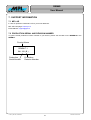
1
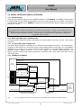
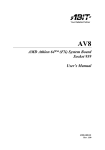
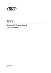
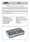
REMMI User Manual General Information This document describes the REMMI (REmote Man Machine Interface) modules. Its purpose is to give all the needed information to the users to set up and install the board successfully. The REMMI concept gives the user the opportunity to connect a remote MMI (Man Machine Interface) to the xIP – Product Family made by MPL. The Product includes two modules that are listed bellow: REMMI-T REMMI-R Transmitter Print Receiver Print General technical features • • • • • • • • ® PanelLink transmission Pixel clock 25MHz up to 86MHz (XGA resolution) PS/2 mouse and keyboard RS232 interface USB interface Panel brightness and/or contrast adjustment through software or on board. Color depth: 24bit/pixel (RGB 3 x 8bit/pixel = 16M colors) 36bit/2pixels (RGB 3 x 6bit/pixel = 256k colors) Optional, power supply from host, up to 10W 2000 by MPL AG, Switzerland 1 REMMI User Manual TABLE OF CONTENTS 1. INTRODUCTION........................................................................................................... 5 1.1 ABOUT THIS MANUAL...................................................................................................................... 5 1.2 SAVETY PRECAUTIONS AND HANDLING...................................................................................... 5 1.3 EQUIPMENT SAFETY........................................................................................................................ 5 2. REMMI CONCEPT........................................................................................................ 6 2.1 BLOCKDIAGRAM .............................................................................................................................. 6 2.2 FEATURES ......................................................................................................................................... 6 2.2.1 Interface........................................................................................................................................... 6 2.2.2 Visibility............................................................................................................................................ 6 2.2.3 Special features ............................................................................................................................... 6 3. REMMI-T....................................................................................................................... 7 3.1 GENERAL INFORMATION ................................................................................................................ 7 3.2 TECHNICAL FEATURES ................................................................................................................... 7 3.3 PARTS LOCATION ............................................................................................................................ 7 3.4 DIP SWITCH 1 SETTINGS ................................................................................................................. 8 ® 3.4.1 PANELLINK INTERFACE.............................................................................................................. 8 3.4.2 RS232 INTERFACE ........................................................................................................................ 8 3.5 CONNECTORS................................................................................................................................... 9 3.5.1 INPUT CONNECTOR...................................................................................................................... 9 3.5.2 OUTPUT CONNECTOR................................................................................................................ 10 3.6 MOUNTING....................................................................................................................................... 11 3.6.1 ELECTRICAL CONSIDERATIONS ............................................................................................... 11 3.6.2 PARTS NEEDED FOR MOUNTING ............................................................................................. 11 3.6.3 MOUNTING DESCRIPTION ......................................................................................................... 11 3.6.4 MECHANICAL DIMENSIONS ....................................................................................................... 12 4. REMMI-R .................................................................................................................... 13 4.1 GENERAL INFORMATION .............................................................................................................. 13 4.2 TECHNICAL FEATURES ................................................................................................................. 13 4.3 CONNECTOR LOCATIONS ............................................................................................................. 14 4.4 DIP SWITCH SETTINGS .................................................................................................................. 15 4.4.1 DIP Switch 1 .................................................................................................................................. 15 4.4.2 DIP Switch 2 .................................................................................................................................. 16 2001 by MPL AG, Switzerland 2 MEH-10074-001 Rev. B REMMI User Manual 4.5 EXTERNAL CONNECTORS ............................................................................................................ 17 4.5.1 INPUT CONNECTOR.................................................................................................................... 17 4.5.2 LCD PANEL CONNECTOR 1 (color depth up to 24bit / pix) ........................................................ 18 4.5.3 LCD PANEL CONNECTOR 2 (color depth up to 36bit / 2 pix) ..................................................... 19 4.5.4 BACKLIGHT INVERTER CONNECTOR....................................................................................... 20 4.5.5 LCD PANEL POWER CONNECTOR............................................................................................ 20 4.5.6 REMMI-R POWER CONNECTOR................................................................................................ 20 4.5.7 USB SINGLE TYPE A CONNECTOR........................................................................................... 21 4.5.8 USB DOUBLE TYPE A CONNECTOR 1 ...................................................................................... 21 4.5.9 USB DOUBLE TYPE A CONNECTOR 2 ...................................................................................... 21 4.5.10 KEYBOARD CONNECTOR ....................................................................................................... 22 4.5.11 MOUSE CONNECTOR .............................................................................................................. 22 4.5.12 SERIAL CONNECTOR .............................................................................................................. 23 4.6 BUTTONS ......................................................................................................................................... 23 4.7 INTERNAL CONNECTORS ............................................................................................................. 24 4.7.1 PASSIVE LCD PANEL CONNECTOR.......................................................................................... 24 4.7.2 TOUCH OPTION CONNECTOR................................................................................................... 25 4.7.3 REMOTE BUTTON CONNECTOR ............................................................................................... 25 4.7.4 GENERAL PURPOSE SIGNALS CONNECTOR.......................................................................... 26 4.8 MOUNTING....................................................................................................................................... 27 4.8.1 ELECTRICAL CONSIDERATIONS ............................................................................................... 27 4.8.2 MECHANICAL DIMENSIONS ....................................................................................................... 28 4.8.2.1 CONNECTOR POSITION ON REMMI-R (FIGURE 1) ........................................................... 28 4.8.2.2 CONNECTOR POSITION ON REMMI-R (FIGURE 2) ........................................................... 29 4.8.2.3 HOLE POSITIONS ON REMMI-R .......................................................................................... 30 4.8.2.4 HEIGHT OF THE REMMI-R WITH SINGLE USB CONNECTOR.......................................... 31 4.8.2.5 HEIGHT OF THE REMMI-R WITH DUAL USB CONNECTORS ........................................... 31 4.9 SERIAL INTERFACE (RS232) FEATURES..................................................................................... 32 4.9.1 INTRODUCTION ........................................................................................................................... 32 4.9.2 RS232 VOLTAGE LEVEL CONNECTORS................................................................................... 32 4.9.3 TTL VOLTAGE LEVEL CONNECTOR.......................................................................................... 32 4.9.4 SCHEMATIC DIAGRAM................................................................................................................ 32 4.10 BRIGHTNESS AND CONTRAST ADJUSTMENT ........................................................................... 33 4.10.1 INTRODUCTION........................................................................................................................ 33 4.10.2 ELECTRICAL CONSIDERATIONS............................................................................................ 33 4.10.3 ADJUSTMENT POSSIBILITIES................................................................................................. 33 4.10.3.1 ON BOARD BUTTONS ON REMMI-R .................................................................................. 33 4.10.3.2 FROM REMOTE BUTTONS TO CONNECTOR ON REMMI-R............................................ 33 4.10.3.3 FROM REMOTE HOST......................................................................................................... 33 4.11 VARIABLE VOLTAGE SELECTION................................................................................................ 34 4.11.1 INTRODUCTION........................................................................................................................ 34 4.11.2 ELECTRICAL CONSIDERATIONS............................................................................................ 34 4.11.3 SCHEMATIC DIAGRAM ............................................................................................................ 34 4.11.4 INTENDED APPLICATION ........................................................................................................ 35 4.12 TOUCH OPTION............................................................................................................................... 36 4.12.1 INTRODUCTION........................................................................................................................ 36 4.12.2 ELECTRICAL CONSIDERATIONS............................................................................................ 36 4.13 FEATURE FLASH CONTROLLER .................................................................................................. 36 5. TRANSMISSION CABLE ........................................................................................... 37 2001 by MPL AG, Switzerland 3 MEH-10074-001 Rev. B REMMI User Manual 5.1 PARTS .............................................................................................................................................. 37 5.2 LENGTH............................................................................................................................................ 37 5.3 ELECTRICAL SPECIFICATION....................................................................................................... 37 ® 5.3.1 PANELLINK INTERFACE............................................................................................................ 37 5.3.2 USB INTERFACE .......................................................................................................................... 37 5.3.3 SERIAL INTERFACE (RS232) ...................................................................................................... 38 5.3.4 PS/2 INTERFACE (MOUSE AND KEYBOARD) ........................................................................... 38 5.3.5 REMMI-R POWER SUPPLY ......................................................................................................... 39 5.3.6 VARIABLE POWER SUPPLY ....................................................................................................... 39 6. INTERNET LINKS*1 .................................................................................................... 40 7. SUPPORT INFORMATION ........................................................................................ 41 7.1 MPL AG............................................................................................................................................. 41 7.2 PRODUCTION SERIAL AND REVISION NUMBER........................................................................ 41 COPYRIGHT AND REVISION HISTORY ......................................................................... 44 MANUAL REVISION INFORMATION ......................................................................................................... 44 DISCLAIMER.................................................................................................................... 44 TRADEMARKS................................................................................................................. 44 2001 by MPL AG, Switzerland 4 MEH-10074-001 Rev. B REMMI User Manual 1. INTRODUCTION 1.1 ABOUT THIS MANUAL This manual is written for use by technical personal responsible for integrating the REMMI modules into their system. The manual assists the installation procedure by providing the necessary information to handle, configure and install the REMMI modules. The REMMI modules are designed to work with the MIP, PIP and IPC from MPL as well as any other IPC’s. It is a easy procedure to set up the REMMI modules, nevertheless, before attempting any installation, please read through all applicable sections of this manual and follow the instructions herein. 1.2 SAVETY PRECAUTIONS AND HANDLING For your personal safety and the save operation of the REMMI products, follow all the safety procedures here and in other sections of the manual. • Power must be removed from the computer system before installing (or removing) any REMMI modules to prevent the possibility of personal injury (electrical shock!) and/or damage to the units. • Handle the units carefully, i.e. dropping or mishandling can damage the modules. • Read and follow all the instructions and warnings described herein. • Keep the REMMI modules away from all sources of liquids, such as coffee cups, drinking glasses, washing facilities etc. • Protect the REMMI modules from humidity. • Keep this manual available for reference. For your protection and that of the REMMI modules, disconnect the power input of the used PIP immediately if any of the following conditions exists: • The power input cable has been damaged. • Something has been spilt onto the modules. • One of the REMMI modules has been damaged in any way, e.g. through dropping. • You suspect that any module requires servicing or repair. WARNING There are no user-serviceable components on any of the REMMI modules! 1.3 EQUIPMENT SAFETY Great care is taken by MPL that all its products are thoroughly and rigorously tested before leaving the factory to ensure that they are fully operational and conform to specification. However, no matter how reliable a product, there is always the remote possibility that a defect may occur. The occurrence of a defect on this device may, under certain conditions, cause a defect to occur in adjoining and/or connected equipment. It is the users responsibility to ensure that adequate protection for such equipment is incorporated when installing this device. MPL accepts no responsibility whatsoever for such kind of defects, however caused. 2001 by MPL AG, Switzerland 5 MEH-10074-001 Rev. B REMMI User Manual 2. REMMI CONCEPT The REMMI (REmote MMI) concept is a Man Machine Interface that serves today needs. In industry the host system may not be at the same place as the MMI, because of the rugged environment. There REMMI concept brings a lot of flexibility with the remote MMI up to 15m. The host system can be placed in a save environment to protect the product and extend its life cycle. The concept consists of two modules, the REMMI-T (transmitter, fitted into the host system) and the REMMIR (receiver, placed near the LCD-Panel). and a connection cable to transmit the signals. 2.1 BLOCKDIAGRAM PANEL INTERFACE PANEL INTERFACE HOST HOST SYSTEM SYSTEM USB USB CONTROL SIGNALS CONTROL SIGNALS RS232 REMMI-T REMMI-T LCD-SIGNALS RS232 TOUCH INTERFACE TOUCH INTERFACE MOUSE INTERFACE MOUSE INTERFACE REMMI-R REMMI-R KEYBOARD KEYBOARD INTERFACE INTERFACE PANELLINK® INTERFACE RS232 INTERFACE RS232 INTERFACE USB INTERFACE USB INTERFACE 2.2 FEATURES 2.2.1 Interface • • • • • PS/2 Interface for mouse PS/2 Interface for keyboard RS232 Interface (only RxD, TxD) USB V1.0 Interface (for cable length up to 5m) Optional, USB(V1.1) Hub 1:4*1 2.2.2 Visibility • • • • • • Up to XGA resolution (1024x768 pixel) Up to 24bit/pix RGB for 16M colors Up to 36bit/2pix RGB for 260K colors Supports TFT, DSTN panels Adjustable brightness 3.3V and 5V LCD panel supported 2.2.3 Special features • • • Option. external power supply for large panel; (power requirement > 10W) Option, flash controller for customer applications*2 Option, touch panel*3 Note: *1: USB Hub 1:4, (one upstream, 4 downstream) *2: Flash controller is also used by MPL *3: The touch panel controller can either use the RS232 lines (RxD, TxD) or the PS/2 mouse interface for communication with the host system 2001 by MPL AG, Switzerland 6 MEH-10074-001 Rev. B REMMI User Manual 3. REMMI-T 3.1 GENERAL INFORMATION The REMMI-T is the transmitter board that can be used with the MPL Products and the REMMI connector or other systems with accurate wiring. The input signals from the VGA controller are converted and sent to the receiver using the PanelLink technology*1. 3.2 TECHNICAL FEATURES • • • • • • • • • Input signals; 3.3V and 5V compatible Up 24bit color/pixel input signals Variable voltage selection*2 Hardware on/off RS232 lines to receiver ESD protected PanelLink signals; by pairs ESD protected USB lines; by pairs ESD protected RS232 lines; RxD, TxD ESD protected PS/2 lines for mouse and keyboard Board dimensions (65 x 75mm) 3.3 PARTS LOCATION Top view Note: *1: For more information please refer to the Silicon Image homepage in section 6 “INTERNET LINKS”. *2: For more information please refer to section: VARIABLE VOLTAGE SELECTION” 4.11. 2001 by MPL AG, Switzerland 7 MEH-10074-001 Rev. B REMMI User Manual O N 3.4 DIP SWITCH 1 SETTINGS 1 2 3 4 5 6 7 8 Default switch settings are in brackets. ® 3.4.1 PANELLINK INTERFACE SW1-1 Latching Edge Data And Control Signals (ON) Latching on falling edge of clock OFF Latching on rising edge of clock SW1-2 Reserved Function ON Reserved (OFF) Reserved SW1-3 Hardware Power down Mode PanelLink Controller ON *1 ® Enabled (OFF) Disabled (normal operation) SW1-4 Software Power down Mode PanelLink Controller *2 ® ON Enabled (OFF) Disabled SW1-5 Reserved Function ON Reserved (OFF) Reserved SW1-8 Adjustable Voltage Swing For PanelLink Transmission ® ON High voltage swing (OFF) Low voltage swing *3 3.4.2 RS232 INTERFACE SW1-6 Enabled OFF Disabled SW1-7 Note: RS232 Transmitter Line (TxD) Connection To Output Connector (ON) RS232 Receiver Line (RxD) Connection To Output Connector (ON) Enabled OFF Disabled *1: If the “Hardware Power down Mode” is enabled, the PanelLink® Controller is turned off. *2: If the “Software Power down Mode” is enabled, the PanelLink® Controller is turned off, while the PD# input signal is LOW. *3: For more information about the “Voltage Swing For PanelLink® Transmission”, please refer to the Datasheet (DS-0001-B) on the Silicon Image Homepage; see “INTERNET LINKS” section 6. 2001 by MPL AG, Switzerland 8 MEH-10074-001 Rev. B REMMI User Manual 3.5 CONNECTORS 3.5.1 INPUT CONNECTOR The input connector is a 50pin (1,27 x 2,54mm) female connector. Pin Signal 1 RE_D6 2 Description Pin Signal Description Color red data bit 6 26 HSYNC Control signal horizontal sync RE_D7 Color red data bit 7 (MSB) 27 CLOCK Data clock 3 RE_D4 Color red data bit 4 28 DE Control signal data enable 4 RE_D5 Color red data bit 5 29 CTRL2 GPIO signal for future use 5 RE_D2 Color red data bit 2 30 CTRL3 GPIO signal for future use 6 RE_D3 Color red data bit 3 31 VCC3 +3.3V 7 RE_D0 Color red data bit 0 (LSB) 32 PD# Power down signal 8 RE_D1 Color red data bit 1 33 VCC +5V 9 GR_D6 Color green data bit 6 34 VCC +5V 10 GR_D7 Color green data bit 7 (MSB) 35 KCLK Keyboard clock 11 GR_D4 Color green data bit 4 36 KDATA Keyboard data 12 GR_D5 Color green data bit 5 37 MCLK Mouse clock 13 GR_D2 Color green data bit 2 38 MDATA Mouse data 14 GR_D3 Color green data bit 3 39 PG Power good signal 15 GR_D0 Color green data bit 0 (LSB) 40 PD0 Control signal 1 for voltage selection 16 GR_D1 Color green data bit 1 41 PD1 Control signal 2 for voltage selection 17 BL_D6 Color blue data bit 6 42 USB+ USB+ signal 18 BL_D7 Color blue data bit 7 (MSB) 43 USB- USB- signal 19 BL_D4 Color blue data bit 4 44 VCC_VAR Variable power line 20 BL_D5 Color blue data bit 5 45 VCC_VAR Variable power line 21 BL_D2 Color blue data bit 2 46 VCC_VAR Variable power line 22 BL_D3 Color blue data bit 3 47 VCC_VAR Variable power line 23 BL_D0 Color blue data bit 0 (LSB) 48 VCC_VAR Variable power line 24 BL_D1 Color blue data bit 1 49 RXD RS232 host receiver 25 VSYNC Control signal vertical sync 50 TXD RS232 host transmitter 1 49 2 50 Samtec RSM-125-02-L-D 50pin (1,27 x 2,54mm) female connector Special signal description: • The two general purpose signals (CTRL2, CTRL3) are not usable for time critical functions, because they are transmitted to the receiver over the PanelLink® interface. For more information please refer to the Silicon Image Homepage; see “INTERNET LINKS” section 6. • PD# (active low signal) can be used either to turn off the REMMI-T PanelLink® Controller (SW1-4 = On) or to shutdown the backlight inverter connected to the REMMI-R board. • The signals PD0, PD1 and PG are used for the function “VARIABLE VOLTAGE SELECTION” section 4.11. 2001 by MPL AG, Switzerland 9 MEH-10074-001 Rev. B REMMI User Manual 3.5.2 OUTPUT CONNECTOR The output connector is a HD-SUB 26 pin female connector. Pin number Signal Description Pinout 1 PL_G- PanelLink green- signal 2 PL_B- PanelLink blue- signal 3 GND Signal ground 4 KDATA Keyboard data line 5 KCLOCK Keyboard clock line 6 MDATA Mouse data line 7 MCLOCK Mouse clock line 8 VCC_VAR Variable power supply 9 RXD 10 PL_R- PanelLink red- signal 11 PL_G+ PanelLink green+ signal 12 PL_CL- PanelLink clock- signal 13 VCC + 5V 14 VCC + 5V 15 GND_VAR Variable ground 16 VCC_VAR Variable power supply 17 GND_VAR Variable ground 18 TXD 19 PL_R+ PanelLink red+ signal 20 PL_B+ PanelLink blue+ signal 21 PL_CL+ PanelLink clock+ signal 22 GND Signal ground 23 USB- USB- line 24 USB+ USB+ line 25 GND_VAR Variable ground 26 VCC_VAR Variable power supply RS232 host receiver line (DTE) 9 18 1 10 26 19 RS232 host transmitter line (DTE) HD-Sub 26 pin female connector Special signal description: • VCC_VAR is the output voltage for the function described in “VARIABLE VOLTAGE SELECTION” section 4.11. 2001 by MPL AG, Switzerland 10 MEH-10074-001 Rev. B REMMI User Manual 3.6 MOUNTING This chapter provides the procedure for mounting the REMMI-T module. If you mount the REMMI-T module yourself into a system, MPL accepts no responsibility for any damage that results to that system or the REMMI-T module. WARNING Before commencing, verify that the host system is switched off and disconnected from the main power. Review and observe the safety precautions description at the beginning of this manual to avoid personal injury or damage to equipment. 3.6.1 ELECTRICAL CONSIDERATIONS There are four holes to mount the REMMI-T module to a base board. The same are also used for GROUND connection. Therefore, the distance pieces to the base board must be electrical conductive. For proper operation use all four mounting holes and connect them to the correct ground potential. IMPORTANT If you don’t connect all four mounting holes to the appropriate ground potential on the base board, the REMMI-T and / or the REMMI-R can be damaged. M1 GND for onboard logic voltage; +5V M2 GND_VAR M3 ESD – GND M4 ESD – GND *1 3.6.2 PARTS NEEDED FOR MOUNTING • • • REMMI-T module 4 x M2.5 x 4mm security screws 4 x Distant connector pieces 3.6.3 MOUNTING DESCRIPTION *2 1. Plug the REMMI-T module to its place . 2. Insert and secure the screws at the mounting holes. All 4 mounting holes must be screwed tight. 3. Insert and secure the screws at the mounting holes. All 4 screws must be tighten well because the GND, GND_VAR and ESD_GND connections are made via the screw connection. Note: *1: Refer to “VARIABLE VOLTAGE SELECTION”, section 4.11 for more information. *2: Please refer to the PIP manual for the REMMI-T mounting location. 2001 by MPL AG, Switzerland 11 MEH-10074-001 Rev. B REMMI User Manual 3.6.4 MECHANICAL DIMENSIONS 73,50mm. 68,00mm. 41,00mm. 7,00mm. 25,32mm. 2 M3 1 J1 58,00mm. 51,00mm. 25,50mm. 7,00mm. M1 50 J2 49 M4 F2 18.60mm. 14.10mm. 7.70mm. 1.60mm. 4.00mm. M2 F2 J1 J3 7,00mm. 41,00mm. 51.50mm. 56.66mm. 67.66mm. 73,50mm. J1 J3 F2 = INPUT CONNECTOR = OUTPUT CONNECTOR = FUSE VCC_VAR 2001 by MPL AG, Switzerland 12 MEH-10074-001 Rev. B REMMI User Manual 4. REMMI-R 4.1 GENERAL INFORMATION The REMMI-R is the receiver board, generally used together with the REMMI-T, to complete the REmote MMI concept. However the REMMI-R can also be used with limited functionality in connection with other ® ® PanelLink Transmitters as well. The received data from the transmitter board, using the PanelLink technology for transmission, is transformed and send to the LCD-Panel. 4.2 TECHNICAL FEATURES • • • • • • • • • • • • Board dimensions (122 x 168mm) No extern power supply needed for panels up to 10W max. power Extern power supply for panels with more than 10W PS/2 mouse and keyboard interface USB interface, connector type A (cable length restricted to 5m, USB Specification 1.0) RS232 interface Supports 3.3V and 5V LCD panels Supports TFT panels up to XGA resolution Supported color resolution: max. 24bit color (3 x 8bit RGB/pixel) one pixel/clock max. 36bit color (3 x 6bit RGB/pixel) two pixel/clock Brightness and contrast adjustment possibilities: on board with push buttons remote and connected to the right connector on the REMMI-R from the host system (Option) *1 Selectable backlight inverter voltage *2 15W max. power consumption Options: • Flash controller AT89S8252 (2kB EEPROM, 8kB Flash, 256Byte RAM, 11GPIO) • USB hub 1:4 with four USB connectors type A (cable length restricted to 5m, USB Specification 1.1) • Supports STN, DSTN • Contrast voltage adjustment from either 0 to –20V or from 0.5 to 20V Note: *1: Refer to the Section ”VARIABLE VOLTAGE SELECTION” section 4.11. *2: Attached periphery: PS/2 mouse and keyboard, lg.philips LCD, LP064V1 (640 x 480) panel 2001 by MPL AG, Switzerland 13 MEH-10074-001 Rev. B REMMI User Manual 4.3 CONNECTOR LOCATIONS Top view 2001 by MPL AG, Switzerland 14 MEH-10074-001 Rev. B REMMI User Manual O N 4.4 DIP SWITCH SETTINGS 1 2 3 4 5 6 7 8 Default switch settings are in brackets. 4.4.1 DIP Switch 1 SW1-1 SW1-2 ON ON (ON) (OFF) OFF ON TxOUT = Tri-state; RxOUT = Tri-state OFF OFF TxOUT = Active; RxOUT = Tri-state SW1-3 TxOUT = Tri-state; RxOUT = Active *1 *2 TxOUT = Active; RxOUT = Active Reserved Function ON Reserved (OFF) Reserved SW1-4 RS232 to TTL Converter, Control Select *3 ON Flash controller controlled (Option) (OFF) DIP switch controlled (SW1-1, SW1-2) SW1-5 TTL Serial Interface (ON) Connection to “General Purpose Signals Connector” OFF Connection to flash controller (DCE) SW1-6 Note: Mode Select of the RS232 to TTL Converter, Hardware Control Reserved Function ON Reserved (OFF) Reserved SW1-7 SW1-8 Voltage VCC_VAR Selection ON ON 5V ±5% ON OFF TBD OFF ON 8V – 28V ±10% (OFF) (OFF) *4 TBD *1: The switch SW1-1 and SW1-2 select the mode of the RS232 to TTL converter on the REMMI-R if the switch SW1-4 is OFF. Otherwise the mode is selected through the flash controller (future option). *2: TxOUT TTL to RS232 conversion, RxOUT RS232 to TTL conversion; TxOUT = RxD direction DTE, RxOUT = TxD direction DTE ( Data Terminal Equipment, host controller) *3: The mode selection of the RS232 to TTL converter can be done, either through the DIP switch SW1-1 and SW1-2 or the flash controller (future option), according to the SW1-4 setting. *4: Refer to the Section ”VARIABLE VOLTAGE SELECTION” for more information. 2001 by MPL AG, Switzerland 15 MEH-10074-001 Rev. B REMMI User Manual 4.4.2 DIP Switch 2 SW2-1 (ON) Falling edge (normal operation) OFF Rising edge SW2-2 Pixel Per Clock Selection (ON) One pixel/clock (up to 24 bit/pixel) OFF Two pixel/clock (up to 18 bit/pixel) SW2-3 Panel Type Selection (ON) TFT panels OFF DSTN panels SW2-4 *1 Output Driver Strength (ON) Low OFF High SW2-5 Note: LCD Panel Data Latch Reserved Function ON Reserved (OFF) Reserved SW2-6 Reserved Function ON Reserved (OFF) Reserved SW2-7 Reserved Function ON Reserved (OFF) Reserved SW2-8 Reserved Function ON Reserved (OFF) Reserved *1: For more information refer to the Datasheet (Sil/DS-0004-B) on the Silicon Image Homepage; see “INTERNET LINKS” section 6. 2001 by MPL AG, Switzerland 16 MEH-10074-001 Rev. B REMMI User Manual 4.5 EXTERNAL CONNECTORS 4.5.1 INPUT CONNECTOR Pin number Signal Description Pinout ® 1 PL_G- PanelLink green- signal 2 PL_B- PanelLink blue- signal 3 GND Signal ground 4 KDATA Keyboard data line 5 KCLOCK Keyboard clock line 6 MDATA Mouse data line 7 MCLOCK Mouse clock line 8 VCC_VAR Variable power supply 9 RXD 10 PL_R- ® RS232 host receiver line (DTE) ® 9 PanelLink red- signal 11 PL_G+ PanelLink green+ signal 12 PL_CL- PanelLink clock- signal 13 VCC + 5V 14 VCC + 5V 15 GND_VAR Variable ground 16 VCC_VAR Variable power supply 17 GND_VAR Variable ground 18 TXD 19 PL_R+ PanelLink red+ signal 20 PL_B+ PanelLink blue+ signal 21 PL_CL+ PanelLink clock+ signal 22 GND Signal ground 23 USB- USB- line 24 USB+ USB+ line 25 GND_VAR Variable ground 26 VCC_VAR Variable power supply 2001 by MPL AG, Switzerland 1 ® ® 18 10 26 19 RS232 host transmitter line (DTE) ® ® ® HD-Sub 26 pin female connector 17 MEH-10074-001 Rev. B REMMI User Manual 4.5.2 LCD PANEL CONNECTOR 1 (color depth up to 24bit / pix) Pin Signal Description Pin Signal Description 1 BL0_E Color blue bit 0 (LSB) pix even 18 GR7_E Color green bit 7 (MSB) pix even 2 BL1_E Color blue bit 1 pix even 19 VCC_PANEL Panel signal power 3 BL2_E Color blue bit 2 pix even 20 GND_PANEL Panel signal ground 4 BL3_E Color blue bit 3 pix even 21 RE0_E Color red bit 0 pix even 5 BL4_E Color blue bit 4 pix even 22 RE1_E Color red bit 1 pix even 6 BL5_E Color blue bit 5 pix even 23 RE2_E Color red bit 2 pix even 7 BL6_E Color blue bit 6 pix even 24 RE3_E Color red bit 3 pix even 8 BL7_E Color blue bit 7 (MSB) pix even 25 RE4_E Color red bit 4 pix even 9 VCC_PANEL Panel signal power 26 RE5_E Color red bit 5 pix even 10 GND_PANEL Panel signal ground 27 RE6_E Color red bit 6 pix even 11 GR0_E Color green bit 0 pix even 28 RE7_E Color red bit 7 (MSB) pix even 12 GR1_E Color green bit 1 pix even 29 CONTRAST Analog contrast voltage 13 GR2_E Color green bit 2 pix even 30 GND_PANEL Panel signal ground 14 GR3_E Color green bit 3 pix even 31 HSYNC Horizontal synch. 15 GR4_E Color green bit 4 pix even 32 VSYNC Vertical synch. 16 GR5_E Color green bit 5 pix even 33 CLK Pixel clock 17 GR6_E Color green bit 6 pix even 34 DE Data enable *1 33 31 29 27 25 23 21 19 17 15 13 11 9 7 5 3 1 34 32 30 28 26 24 22 20 18 16 14 12 10 8 6 4 2 Male header 34 pin (2.54 x 2.54mm) 2001 by MPL AG, Switzerland 18 MEH-10074-001 Rev. B REMMI User Manual 4.5.3 LCD PANEL CONNECTOR 2 (color depth up to 36bit / 2 pix) Pin Signal Description Pin Signal Description 1 BL0_O Color blue bit 0 (LSB) pix odd 14 GR3_O Color green bit 3 pix odd 2 BL1_O Color blue bit 1 pix odd 15 GR4_O Color green bit 4 pix odd 3 BL2_O Color blue bit 2 pix odd 16 GR5_O Color green bit 5 pix odd 4 BL3_O Color blue bit 3 pix odd 17 GR6_O Color green bit 6 pix odd 5 BL4_O Color blue bit 4 pix odd 18 GR7_O Color green bit 7 (MSB) pix odd 6 BL5_O Color blue bit 5 pix odd 19 RE0_O Color red bit 0 pix odd 7 BL6_O Color blue bit 6 pix odd 20 RE1_O Color red bit 1 pix odd 8 BL7_O Color blue bit 7 (MSB) pix odd 21 RE2_O Color red bit 2 pix odd 9 VCC_PANEL Panel signal power 22 RE3_O Color red bit 3 pix odd 10 GND_PANEL Panel signal ground 23 RE4_O Color red bit 4 pix odd 11 GR0_O Color green bit 0 pix odd 24 RE5_O Color red bit 5 pix odd 12 GR1_O Color green bit 1 pix odd 25 RE6_O Color red bit 6 pix odd 13 GR2_O Color green bit 2 pix odd 26 RE7_O Color red bit 7 (MSB) pix odd 25 23 21 19 17 15 13 11 9 7 5 3 1 26 24 22 20 18 16 14 12 10 8 6 4 2 Male header 13 pin (2.54 x 2.54mm) Note: *1: For more information refer to: “BRIGHTNESS AND CONTRAST ADJUSTMENT” section 4.10. 2001 by MPL AG, Switzerland 19 MEH-10074-001 Rev. B REMMI User Manual 4.5.4 BACKLIGHT INVERTER CONNECTOR Pin number Signal Description Pinout 1 VCC_BL Backlight inverter power supply 2 VCC_BL Backlight inverter power supply 3 VCC_BL Backlight inverter power supply 4 ON / OFF_BL Backlight inverter ON/OFF 5 ON / OFF_BL Backlight inverter ON/OFF 6 NC 7 BRIGHTNESS 8 GND_BL Backlight inverter ground 9 GND_BL Backlight inverter ground 10 GND_BL Backlight inverter ground *1 Analog brightness adjustment 9 7 5 3 1 10 8 6 4 2 *2 Male header 10 pin bolted 4.5.5 LCD PANEL POWER CONNECTOR If the panel exceeds 10W, the power supply must be provided from an external source. If you connect an external power supply, be aware, that the applied power is connected right to the backlight inverter (pin 1 and 2) and the LCD panel (pin 3 and 4). WARNING The backlight inverter as well as the LCD panel may be damaged if the wrong voltage level is applied. MPL is not liable for any damage to the system or the attached peripherals resulting from the wrong applied voltage level to this connector. Pin number Signal Description Pinout 1 VCC_BL Input power backlight inverter 2 GND_BL Input ground backlight inverter 3 RESERVED Reserved for future use 4 RESERVED Reserved for future use 1 2 3 4 LCD panel power connector 4.5.6 REMMI-R POWER CONNECTOR The VCC_VAR and the GND_VAR signal are used to supply the backlight inverter with power up to 10W. For further information see section 4.11“ VARIABLE VOLTAGE SELECTION ”. Pin number Signal 1 VCC_VAR Variable power supply 2 GND_VAR Variable ground 3 VCC +5V 4 GND Ground Note: Description Pinout 1 2 3 4 REMMI-R power connector *1: The backlight inverter is turned on if ON / OFF_BL is at 5V. *2: For more information please refer to: “BRIGHTNESS AND CONTRAST ADJUSTMENT” in section 4.10. 2001 by MPL AG, Switzerland 20 MEH-10074-001 Rev. B REMMI User Manual 4.5.7 USB SINGLE TYPE A CONNECTOR The USB interface is according to the USB specification Rev.1.0 implemented. The cable length of the USB connection is up to 5m, according to the USB specification. Pin number Signal Description 1 VCC Cable Power +5V 2 -Data Balanced Data Line - 3 +Data Balanced Data Line + 4 GND Cable Ground Pinout 1 2 3 4 USB Type A 4.5.8 USB DOUBLE TYPE A CONNECTOR 1 Pin number Signal Description 1 VCC1 Port 0 Cable Power +5V 2 -Data1 Port 0 Balanced Data Line - 3 +Data1 Port 0 Balanced Data Line + 4 GND1 Port 0 Cable Ground 5 VCC2 Port 1 Cable Power +5V 6 -Data2 Port 1 Balanced Data Line - 7 +Data2 Port 1 Balanced Data Line + 8 GND2 Port 1 Cable Ground Pinout 5 6 7 8 1 2 3 4 Dual USB (Type A) 4.5.9 USB DOUBLE TYPE A CONNECTOR 2 Pin number Signal 1 VCC3 Port 3 Cable Power +5V 2 -Data3 Port 3 Balanced Data Line - 3 +Data3 Port 3 Balanced Data Line + 4 GND3 Port 3 Cable Ground 5 VCC4 Port 4 Cable Power +5V 6 -Data4 Port 4 Balanced Data Line - 7 +Data4 Port 4 Balanced Data Line + 8 GND4 Port 4 Cable Ground 2001 by MPL AG, Switzerland Description Pinout 5 6 7 8 1 2 3 4 Dual USB (Type A) 21 MEH-10074-001 Rev. B REMMI User Manual 4.5.10 KEYBOARD CONNECTOR PS/2 keyboard interface. Pin number Signal Description 1 KDAT Keyboard data 2 NC Not connected 3 GND Ground 4 VCC +5V Pinout 5 6 3 4 5 KCLK 2 1 MiniDIN6 Keyboard clock 4.5.11 MOUSE CONNECTOR *1 PS/2 mouse interface. Do not connect a device to this connector, if the touch option over PS/2 is used. Pin number Signal 1 MDAT 2 NC 3 GND Ground 4 VCC +5V 2 5 MCLK Mouse clock MiniDIN6 Note: Description Pinout Mouse data 5 6 Not connected 3 4 1 *1: For more information see the section 4.12“TOUCH OPTION”. 2001 by MPL AG, Switzerland 22 MEH-10074-001 Rev. B REMMI User Manual 4.5.12 SERIAL CONNECTOR The serial interface (RS232 interface) has no handshake and control signals. Do not connect a device to this *1 connector if the onboard RS232 controller is used with the host system. Pin number Signal Description 1 NC 2 RXD Receive data 3 TXD Transmit data 4 NC Not connected 5 GND 6 NC Not connected 7 NC Not connected 8 NC Not connected 9 NC Not connected Pinout Not connected *2 1 5 Ground 6 9 DSUB9 male connector 4.6 BUTTONS *3 The buttons 1 – 4 are used for contrast and/or brightness adjustment. Button number Signal Description Button 1 BRI_POS Increase brightness Button 2 BRI_NEG Decrease brightness Button 3 CON_POS Increase contrast (used mainly for DSTN panels) Button 4 CON_NEG Decrease contrast (used mainly for DSTN panels) Note: *1: For more information about all the possible features using the serial interface refer to section 4.9 “SERIAL INTERFACE (RS232) FEATURE”. *2: RxD and TxD for DTE (Data Terminal Equipment). *3: See “BRIGHTNESS AND CONTRAST ADJUSTMENT” section 4.10. 2001 by MPL AG, Switzerland 23 MEH-10074-001 Rev. B REMMI User Manual 4.7 INTERNAL CONNECTORS 4.7.1 PASSIVE LCD PANEL CONNECTOR Pin number Signal Description 1 VCC 2 VCC_PANEL Power LCD panel 3 VCC_PANEL Power LCD panel 4 RESERVED Do not connect 5 RESERVED Do not connect 6 RESERVED Do not connect 7 RESERVED Do not connect 8 SDA Flash controller port0 pin1 9 SCL Flash controller port0 pin2 10 RESERVED Do not connect 11 RESERVED Do not connect 12 RESERVED Do not connect 13 GND Ground 14 GND Ground 15 GND Ground 16 GND Ground + 5V 2 4 6 8 10 12 14 16 1 3 5 7 9 11 13 15 Passive LCD panel connector 2001 by MPL AG, Switzerland 24 MEH-10074-001 Rev. B REMMI User Manual 4.7.2 TOUCH OPTION CONNECTOR Pin number Signal Description 1 NC Not connected 2 NC Not connected 3 RxD Receive data 4 MCLK 5 TxD 6 MDATA 7 VCC 8 NC 9 GND 10 NC *1 PS/2 mouse clock Transmit data *1 PS/2 mouse data + 5V Not connected Ground Not connected 2 4 6 8 10 1 3 5 7 9 Touch option connector 4.7.3 REMOTE BUTTON CONNECTOR Pin number Signal Description 1 BRI_POSEXT Remote, increase brightness 2 BRI_NEGEXT Remote, decrease brightness 3 CON_POSEXT Remote, increase contrast 4 CON_NEGEXT Remote, decrease contrast 5 VCC + 5V 6 GND Ground 7 VCC3 + 3.3V 8 GND Ground 9 SDA Flash controller port0 pin1 10 SCL Flash controller port0 pin2 2 4 6 8 10 1 3 5 7 9 Remote button connector Note: *1: RxD and TxD for DTE (Data Terminal Equipment). 2001 by MPL AG, Switzerland 25 MEH-10074-001 Rev. B REMMI User Manual 4.7.4 GENERAL PURPOSE SIGNALS CONNECTOR Pin number Signal Description 1 VCC + 5V 2 VCC3 + 3.3V 3 FP3.2 Flash controller port3 pin2 4 FP3.3 Flash controller port3 pin3 5 FP3.4 Flash controller port3 pin4 6 FP3.5 Flash controller port3 pin5 7 FP3.6 Flash controller port3 pin6 8 FP3.7 Flash controller port3 pin7 9 TxD RS232 transmit signal TTL level (DCE) 10 RxD RS232 receive signal TTL level (DCE) 11 FTxD Flash controller port3 pin1 12 FRxD Flash controller port3 pin0 13 RESERVED Do not connect 14 RESERVED Do not connect 15 RESERVED Do not connect 16 GND Ground 17 VCC + 5V 18 MPL USE ONLY Do not connect 19 MPL USE ONLY Do not connect 20 MPL USE ONLY Do not connect 21 MPL USE ONLY Do not connect 22 FMOSI Flash controller port1 pin5 23 FMISO Flash controller port1 pin6 24 FCLK Flash controller port1 pin7 25 FRST Flash controller reset 26 GND Ground 2 4 6 8 10 12 14 16 18 20 22 24 26 1 3 5 7 9 11 13 15 17 19 21 23 25 General purpose signals connector 2001 by MPL AG, Switzerland 26 MEH-10074-001 Rev. B REMMI User Manual 4.8 MOUNTING This chapter provides the procedure for mounting the REMMI-R module. The mounting holes are placed in a way, that the REMMI-R module fits direct on the back of the LP064V1, a 6.4” TFT panel from Lucky Goldstar (LG). Other LCD displays can be certainly mounted as well. If you mount the REMMI-R module yourself into a system, MPL accepts no responsibility for any damage that result to that system or the REMMI-R module. WARNING Before commencing, verify that REMMI-R is switched off and disconnected from all powers. Review and observe the safety precautions description at the beginning of this manual to avoid personal injury or damage to equipment. 4.8.1 ELECTRICAL CONSIDERATIONS There are six holes on the REMMI-R to be used for mounting the module. The other four holes are either connected to ground (shouldn’t be used because of possible ground loop connections) or are reserved for future use. IMPORTANT Do not use the holes connected to the ground for mounting the REMMI-R modules. A resulting ground loop can disturb the data transmission and result in a nonfunctioning system. M1 ESD – GND connection, mounting hole M2 ESD – GND connection, mounting hole M3 ESD – GND connection, mounting hole M4 Not connected, reserved for future use M5 Not connected, reserved for future use M6 GND connection, no mounting hole M7 GND connection, no mounting hole M8 ESD – GND connection, mounting hole M9 ESD – GND connection, mounting hole M10 ESD – GND connection, mounting hole 2001 by MPL AG, Switzerland 27 MEH-10074-001 Rev. B REMMI User Manual 4.8.2 MECHANICAL DIMENSIONS 22.00mm. 4.8.2.1 CONNECTOR POSITION ON REMMI-R (FIGURE 1) M9 M4 M1 3.00mm. M6 5.00mm. 18.50mm. 45.50mm. 60.00mm. 99.00mm. 105.00mm. 12.00mm. M2 M5 M7 24.00mm. 13.00mm. M8 M10 M3 35.00mm. 46.00mm. 69.16mm. 94.30mm. 110.80mm. 132.30mm. 149.30mm. 165.00mm. Connector position on REMMI-R, figure 1 2001 by MPL AG, Switzerland 28 MEH-10074-001 Rev. B REMMI User Manual 4.8.2.2 CONNECTOR POSITION ON REMMI-R (FIGURE 2) 172.00mm. 124.40mm. 74.40mm. 28.00mm. 22.00mm. 39.00mm. 71.30mm. M9 M1 M4 M6 5.00mm. 15.32mm. 60.00mm. 34.25mm. 79.45mm. 73.74mm. 99.00mm. 82.63mm. 22.40mm. 12.00mm. 3.00mm. 2.08mm. M2 M5 M7 M8 M3 M10 44.63mm. 68.76mm. 165.00mm. Connector position on REMMI-R figure 2 2001 by MPL AG, Switzerland 29 MEH-10074-001 Rev. B REMMI User Manual 18.50mm. 22.00mm. 4.8.2.3 HOLE POSITIONS ON REMMI-R M9 M1 M4 5.00mm. 15.32mm. 60.00mm. 64.00mm. 64.85mm. 93.50mm. 92.50mm. 99.00mm. M6 40.00mm. 53.52mm. 3.00mm. M2 M5 M7 M8 M3 M10 2.85mm. 40.00mm. 83.36mm. 121.30mm. 162.00mm. 165.00mm. Hole positions on REMMI-R 2001 by MPL AG, Switzerland 30 MEH-10074-001 Rev. B REMMI User Manual 4.8.2.4 HEIGHT OF THE REMMI-R WITH SINGLE USB CONNECTOR 172.00mm. 167.00mm. 165.00mm. 132.31mm. 124.40mm. 110.80mm. 94.30mm. 69.16mm. 46.00mm. 44.36mm. 35.00mm. 24.00mm. 13.00mm. 2.08mm. 3.00mm. J30 7.32mm. 10.97mm. 12.47mm. 13.97mm. 11.00mm. 12.50mm. 14.00mm. 16.00mm. 1.67mm. 4.00mm. 7.00mm. 8.50mm. 10.00mm. Distance under the board min. 4mm Height of the REMMI-R with single USB connector 4.8.2.5 HEIGHT OF THE REMMI-R WITH DUAL USB CONNECTORS 172.00mm. 167.00mm. 165.00mm. 149.31mm. 132.31mm. 124.40mm. 110.80mm. 94.30mm. 69.16mm. 46.00mm. 44.36mm. 35.00mm. 24.00mm. 13.00mm. 2.08mm. 3.00mm. J30 1.67mm. 4.00mm. 7.00mm. 8.50mm. 10.00mm. Distance under the board min. 4mm Height of the REMMI-R with dual USB connectors 2001 by MPL AG, Switzerland 31 MEH-10074-001 Rev. B REMMI User Manual 4.9 SERIAL INTERFACE (RS232) FEATURES 4.9.1 INTRODUCTION There are many different options to use the RS232 interface on the REMMI-R. The REMMI concept support the signals RxD and TxD. Hardware handshake or the other modem signals are not available. The RxD and TxD signals are available on the REMMI-R on different connectors and with different voltage levels (RS232 level and TTL level). IMPORTANT Be aware that the RS232 serial interface is a point to point interface. Therefor only one device from the REMMI-R can be connected to the host system. If you use of the flash controller or the TTL signals on the “General Purpose Signals Connector”, no other device can be attached on the RS232 voltage level connectors, and vice versa. 4.9.2 RS232 VOLTAGE LEVEL CONNECTORS The serial interface signals are always connected to the “Serial Interface Connector” and the “Touch Option Connector”. 4.9.3 TTL VOLTAGE LEVEL CONNECTOR *1 The serial interface signals are available on the “General Purpose Signals Connector”. The onboard flash controller can also be used to communicate over the serial interface with the host system. The “SCHEMATIC DIAGRAM 4.9.4” shows how to connect either the flash controller or the serial interface signals on the “General Purpose Signal Connector” to the host system. The signals RS232_RxD_DTE and RS232_TxD_DTE are the serial interface signals also connected to the “Touch Option Connector” and the “Serial Connector”. 4.9.4 SCHEMATIC DIAGRAM TTL_TxD_DCE TTL_RxD_DCE Flash Controller SW1-4 = ON RS232_SHDN SW1-4 = OFF SW1-4 = ON 1 O 2 N RS232_EN SW1-4 = OFF SW1 3 SW1-4 4 SW1-5 5 6 7 RS232_EN = 0 8 RS232_TxD_DTE RS232_EN = 1 RS232_SHDN = 1 RS232_RxD_DTE SW1-5 = OFF TTL_TxD_DTE SW1-5 = ON 10 General Purpose Signals Connector SW1-5 = OFF TTL_RxD_DTE SW1-5 = ON RS232_SHDN = 0 TTL_TxD_DCE 9 SWITCH RS232 TO TTL CONVERTER Note: TTL_RxD_DCE *1: For using the flash controller with the serial interface some software has to be written for the flash controller. 2001 by MPL AG, Switzerland 32 MEH-10074-001 Rev. B REMMI User Manual 4.10 BRIGHTNESS AND CONTRAST ADJUSTMENT 4.10.1 INTRODUCTION Depending on the light of the surrounding where the LCD display is used, the brightness eventually needs to be adjusted. For the TFT-panel the backlight is used to adjust the brightness. With the STN / DSTN there is also a “Contrast” signal used to select the brightness. Today TFT panels are far more often used and therefore we describe TFT panels in this manual. 4.10.2 ELECTRICAL CONSIDERATIONS The “ BRIGHTNESS” signal on the Backlight Inverter Connector can be adjusted from 0 to 5V. The default setting is 2.5V. 4.10.3 ADJUSTMENT POSSIBILITIES 4.10.3.1 ON BOARD BUTTONS ON REMMI-R With the on board buttons the brightness can be adjusted easily. While keeping the button pressed, after a delay time the brightness in-/decreases automatically. For fine tuning press the specific button repeatedly until the right brightness is set. 4.10.3.2 FROM REMOTE BUTTONS TO CONNECTOR ON REMMI-R The remote buttons work alike the once on board. See the scheme below for connection information: REMOTE BUTTONS +5V REMOTE BUTTON CONNECTOR BRIGHTNESS INCREASE 1 REM_BRI_POS 2 REM_BRI_NEG 3 REM_CON_POS 4 REM_CON_NEG 5 BRIGHTNESS DECREASE CONTRAST INCREASE +5V CONTRAST DECREASE 6 7 +3.3V 8 9 FLASH CONTROLLER PORT0 PIN1 10 FLASH CONTROLLER PORT0 PIN2 GND 4.10.3.3 FROM REMOTE HOST This option can only be used if supported by the host system. For this reason there a two general purpose signals available on the REMMI-T. CTRL2 and CTRL3 are used to adjust the panel contrast and/or brightness from the host system. The signals are edge sensitive and are assigned as following: CTRL2 0 0 1 ↑ ↓ 1 CTRL3 0 ↑ ↓ 0 1 1 Action No change brightness + brightness contrast + contrast No change REMARK: That an edge is detected the signals have to be stable in the new state for at least 0.5ms. No edge is detected if the signals change together within 100us. 2001 by MPL AG, Switzerland 33 MEH-10074-001 Rev. B REMMI User Manual 4.11 VARIABLE VOLTAGE SELECTION 4.11.1 INTRODUCTION Besides the +5V voltage (used for REMMI-R, REMMI-T) and the 3.3V voltage (used only for REMMI-T), the REMMI modules uses a variable voltage. There is the possibility to give a selection of up to four different voltage levels, supported from the host system. From those, the right voltage level can be chosen on the REMMI-R. See the scheme diagram below for more information. 4.11.2 ELECTRICAL CONSIDERATIONS The voltage selection is initialized after reset. After a delay of 3sec, either the right voltage is applied from the host system to the REMMI-R or no voltage is applied and the feature is turned off. The voltage selection circuit on the host side has to control the selected voltage applied. The max. power supplied by the host system for the VCC_VAR voltage is 10W. IMPORTANT Be aware that if you use the REMMI modules in an other system than the xIP from MPL, that your voltage selection circuit has to control, if the right voltage is applied according to the selection. The variable voltage from the host, has to be turned off if the selected voltage doesn’t have the proper level. The following voltage level are defined: SW1-7 SW1-8 Voltage VCC_VAR Selection ON ON 5V ±5% ON OFF TBD OFF ON 8V – 28V ±10% (OFF) (OFF) TBD 4.11.3 SCHEMATIC DIAGRAM 1 O 2 N 3 PD0 4 PD1 5 6 POWER GOOD LOGIC PG 7 5V / 1.5A PD0 = ON PD1 = ON TBD PD0 = ON PD1 = OFF 8V.. 28V / 1A..0.25A PD0 = OFF PD1 = ON TBD PD0 = OFF PD1 = OFF PG = 1 VCCVAR VCCVAR GNDVAR GNDVAR SELECTABLE INPUT VOLTAGES PIN 1 PIN 2 GNDVAR HOST SYSTEM REMMI-T TRANSMISSION LINES REMMI-R POWER CONNECTOR 8 REMMI-R If the PG (Power Good) signal is high, the selected VCC_VAR (REMMI-T input) voltage is put through to the REMMI-R. 2001 by MPL AG, Switzerland 34 MEH-10074-001 Rev. B REMMI User Manual 4.11.4 INTENDED APPLICATION This feature has mainly built in the system to supply the LCD display backlight inverter with power from the host system. This solution allows to supply the whole REmote MMI (REMMI) interface from the host system if the needed power is less than 10W. This feature can also be used for many other application that use less than 10W total power. 2001 by MPL AG, Switzerland 35 MEH-10074-001 Rev. B REMMI User Manual 4.12 TOUCH OPTION 4.12.1 INTRODUCTION The “Touch Option” can be used to attach a touch screen to the system. 4.12.2 ELECTRICAL CONSIDERATIONS There are many different kind of touch controllers, using also many different kind of interface protocols to connect the touch screen to the system. The REMMI-R supports two of those: • Touch controller interface over RS232 (if touch controller only uses RxD and TxD signals) • Touch controller interface over PS/2 (mouse) If you use the serial interface (RS232), the Serial Connector can’t be used and the DIP-switch has the following setting: • SW1-4 = OFF • SW1-2 = ON • SW1-3 = OFF If you use the PS/2 (mouse) interface, the external Mouse Connector can not be used. For more information please refer to the touch controller manual. 4.13 FEATURE FLASH CONTROLLER The on board flash controller is mainly used for the panel brightness and contrast adjustment. However there is still the possibility to use it for other applications as well. The serial TTL level interface, allows communication to the host or, if the flash controller is used as a host, to the General Purpose Signals Connector. For customer applications, the flash controller may be usable, if the it doesn’t interfere with the main program. 2001 by MPL AG, Switzerland 36 MEH-10074-001 Rev. B REMMI User Manual 5. TRANSMISSION CABLE 5.1 PARTS The parts needed to connect the REMMI-T and the REMMI-R together are listed bellow: • Two HD-Sub 25 pin male connector in a conductive cover 5.2 LENGTH The cable length is restricted to 15m for the LCD displays with a resolution up to 1024x768 (XGA). If the USB interface is used, the max. length is 5m, according to the USB specification V1.0. Because of the different cable quality, MPL can not be made reliable of pixel errors on the LCD display. To solve those problems, reduce the cable length or us a better cable quality from another manufacturer. 5.3 ELECTRICAL SPECIFICATION ® 5.3.1 PANELLINK INTERFACE • • • • • • 4 twisted pairs Each pair single shielded Shielded as a hole cable CAT5 cable AWG 28 Characteristic impedance Z0 = 100 Ohm +/- 15% SIGNAL PAIR DEFINITION Pair Signal Description ® 1 PL_G- PanelLink green- signal 1 PL_G+ PanelLink green+ signal 2 PL_R- PanelLink red- signal 2 PL_R+ PanelLink red+ signal 3 PL_B- PanelLink blue- signal 3 PL_B+ PanelLink blue+ signal 4 PL_CL- PanelLink clock- signal 4 PL_CL+ PanelLink clock+ signal ® ® ® ® ® ® ® REMARK: It is important to stay to the „SIGNAL PAIR DEFINITION“ to increase signal immunity against interferences and improve picture quality. 5.3.2 USB INTERFACE • • • • 1 twisted pair shielded CAT5 AWG 28 Characteristic impedance Z0 = 90 Ohm +/- 15% SIGNAL PAIR DEFINITION Pair Signal Description 1 USB- USB- line 1 USB+ USB+ line REMARK: It is important to stuck to the „SIGNAL PAIR DEFINITION“ to increase signal immunity against interferences and transmission quality. 2001 by MPL AG, Switzerland 37 MEH-10074-001 Rev. B REMMI User Manual 5.3.3 SERIAL INTERFACE (RS232) • • 1 twisted pair AWG 24 SIGNAL PAIR DEFINITION Pair Signal Description 1 RxD Receive line RS232 (DTE) 1 TxD Transmission line RS232 (DTE) REMARK: It is important to stuck to the „SIGNAL PAIR DEFINITION“ to increase signal immunity against interferences and transmission quality. 5.3.4 PS/2 INTERFACE (MOUSE AND KEYBOARD) • • 2 twisted pairs AWG 24 SIGNAL PAIR DEFINITION Pair Signal Description 1 KCLOCK Keyboard clock line 1 KDATA Keyboard data line 2 MCLOCK Mouse clock line 2 MDATA Mouse data line REMARK: It is important to stuck to the „SIGNAL PAIR DEFINITION“ to increase signal immunity against interferences and transmission quality. 2001 by MPL AG, Switzerland 38 MEH-10074-001 Rev. B REMMI User Manual 5.3.5 REMMI-R POWER SUPPLY Each twisted pair includes a VCC and a GND signal. • 2 twisted pairs • AWG 22 • Current load: min. 1A a pair SIGNAL PAIR DEFINITION Pair Signal Description 1 VCC + 5V power 1 GND Ground 2 VCC + 5V power 2 GND Ground 5.3.6 VARIABLE POWER SUPPLY Each twisted pair includes a VCC_VAR and a GND_VAR signal. • 3 twisted pairs • AWG 22 • Current load: min. 1A a pair SIGNAL PAIR DEFINITION Pair 2001 by MPL AG, Switzerland Signal Description 1 VCC_VAR Variable power supply 1 GND_VAR Variable ground 2 VCC_VAR Variable power supply 2 GND_VAR Variable ground 3 VCC_VAR Variable power supply 3 GND_VAR Variable ground 39 MEH-10074-001 Rev. B REMMI User Manual 6. INTERNET LINKS*1 • MPL AG http://www.mpl.ch • ATMEL AT98S8252 http://www.atmel.com/products/prod71.htm • SILICON IMAGE http://www.siimage.com • LG.PHILIPS LCD http://www.lgphilips-lcd.com:8888/English/product/p.html Note: *1: Links may have changed in the meantime. The latest links can also be found on the MPL homepage http://www.mpl.ch/ 2001 by MPL AG, Switzerland 40 MEH-10074-001 Rev. B REMMI User Manual 7. SUPPORT INFORMATION 7.1 MPL AG In case of questions contact MPL AG or your local distributor. MPL AG homepage: www.mpl.ch Email address: [email protected] 7.2 PRODUCTION SERIAL AND REVISION NUMBER To get the actual production revision number of your device, please see the label on the REMMI-R or the REMMI-T. Product Name REMMI-T-1 SN: 109 ( B ) Production Serial Number 2001 by MPL AG, Switzerland Production Revision Number 41 MEH-10074-001 Rev. B REMMI User Manual This page is intentionally left blank. 2001 by MPL AG, Switzerland 42 MEH-10074-001 Rev. B REMMI User Manual This page is intentionally left blank. 2001 by MPL AG, Switzerland 43 MEH-10074-001 Rev. B REMMI User Manual COPYRIGHT AND REVISION HISTORY Copyright © 2001 by MPL AG Elektronikunternehmen. All rights are reserved. Reproduction of this document in part or whole, by any means is prohibited, without written permission from MPL AG Elektronikunternehmen. MANUAL REVISION INFORMATION Date Revision No. June 2000 A December 2001 B Remarks This manual reflects the following revisions of the REMMI modules: REMMI-R Rev. A REMMI-T Rev. A REMMI-5 Rev. A REMMI-RS Rev. A This manual reflects the following or higher revisions of the REMMI modules: REMMI-R Rev. B REMMI-T Rev. B DISCLAIMER All implied warranties on the product and manuals, including implied warranties or merchantability and fitness for a particular purpose, are limited in duration to twelve (12) months from the date of the original retail purchase of this product. MPL has fully tested the REMMI modules and reviewed the documentation. However, MPL makes no warranty or representation, either expressed, or implied, with respect to this product, its quality, performance, merchantability, or fitness for a particular purpose. In no event will MPL be liable for direct, indirect, special, incidental, or consequential damages resulting from any defect in the product or its documentation, even if advised of the possibility of such damages. In particular MPL shall have no liability for any parts connected to this product. MPL AG reserves the right to make changes to any product herein to improve reliability, function or design. TRADEMARKS Brand or product names are trademarks and registered trademarks of their respective holders. 2001 by MPL AG, Switzerland 44 MEH-10074-001 Rev. B