1
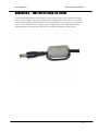
iScan plusv2
User Manual
i Scan Plus User Manual
Table of Contents
TABLE OF CONTENTS
2
INTRODUCTION
4
IN A NUTSHELL
5
INSTALLATION
OPERATION
5
6
INSTALLATION AND SETUP
7
TYPICAL CONFIGURATION
SYSTEM REQUIREMENTS
CONNECTIONS
COLOR SPACE S ELECTION
SYNCHRONIZATION SIGNALS
7
8
8
10
10
OPERATION
12
INPUT S ELECTION
ASPECT RATIO CONTROL / SQUEEZE M ODE
PROCESSING MODE INDICATORS
POWER USAGE AND ENVIRONMENTAL R EQUIREMENTS
12
12
13
13
TROUBLESHOOTING
14
HOW IT WORKS
17
B ACKGROUND
DEINTERLACING
VIDEO PROCESSING
17
18
19
TECHNICAL SPECIFICATIONS
20
WARRANTY INFORMATION
21
2
i Scan Plus User Manual
SAFETY INFORMATION:
22
SAFEGUARDS
PRECAUTIONS :
22
22
APPENDIX A – INTERNAL JUMPER SETTINGS
23
REMOVING THE ISCAN P LUS V2 MOTHERBOARD
MODIFYING COMPOSITE SYNC J UMPER S ETTING
MODIFYING S YNC-ON -GREEN J UMPER S ETTING
MODIFYING VCR MODE J UMPER S ETTING
REASSEMBLING THE ISCAN P LUS V2
23
23
24
24
24
APPENDIX B – EMI FERRITE SNAP-ON COLLAR
26
Note:
♦
DVDO, PureProgressive, i Scan, iScan, iScan Plus and iScan Plus v2 are
trademarks of Silicon Image, Inc. This product is covered by pending U.S.
and foreign patents.
3
Silicon Image, Inc.
i Scan Plus v2 User Manual
Introduction
Your iScan Plus v2 package contains:
•
•
•
•
•
•
•
iScan Plus v2 Line Doubling Upconverter
Universal power supply module
Power cable
Composite input cable
S-Video input cable
Warranty card
User Manual
Your iScan Plus v2 package does not contain an output cable. You will need to get an output
cable that works with your display device. There is more information on these cables in the
Installation section.
The iScan Plus v2 is designed to interface to 31.5 kHz progressively scanned display devices such
as:
♦
♦
♦
♦
♦
HDTVs
Progressive scan and Multimedia TVs
Plasma TVs
Data projectors
Home Theater video projectors (31.5KHz scan rate required)
If you are not sure if your display will work with the iScan Plus v2, check the compatibility list on
our web site (www.dvdo.com).
4
Silicon Image, Inc.
i Scan Plus v2 User Manual
In a Nutshell
If you already know about line doublers and have had experience installing these devices, here’s
a summary of what is unique about the iScan Plus v2.
Installation
The iScan Plus v2 has 3 input ports and 1 output port. The inputs are auto-sensing and switching
which means that they will automatically switch to whichever input is active. The “Input
Priority” switch allows you to select which input should be used when more than one is active.
We recommend using S-Video inputs for DVD players, satellite receivers and/or digital cable
boxes. For VCRs or laserdisc players, chances are good that using the composite video input will
give you a better picture because of the very good Y/C separator in the iScan Plus v2. However,
you should try both composite and S-Video to see which works better in your system.
There are two switches that are of interest during installation. The first, the “Input Priority”
switch was described above. The second is the “Colorspace” select switch on the back panel and
is used to change the output colorspace from RGB to component video (YPrPb), to match the
characteristics of your display device. If your display supports progressive 31.5kHz signals on
both RGB and YPrPb inputs, we generally recommend using YPrPb due to the increase color
controls available.
The iScan Plus v2 has a single video output connector which is the same connector used by the
computer industry to connect computer monitors to computers. This connector is called an HD15, or VGA connector and has Red, Green, Blue, H Sync and V Sync signals. However, if
Component Video (YPrPb) colorspace is selected using the colorspace switch, Y, Pr and Pb
signals are placed on the Green, Red and Blue signal pins, respectively.
A high quality VGA-to-VGA computer monitor cable should be used to connect the iScan Plus
v2’s output to devices that can only accept progressive signals through a VGA connector.
A standard VGA-to-BNC breakout cable can be used to attach the iScan Plus v2 to any projector
or television that has BNC connectors. Your iScan dealer may stock these cables or, if not, they
should be able to recommend a store that does carry them.
A set of three BNC-to-RCA adapters can be used with this same cable for connecting to
televisions with component video RCA inputs. In this case, no sync signals are required so the
gray (or white) and black wires can be left unconnected. These are available at higher-end video
houses or electronics supply stores like Radio Shack.
For RGB devices, the iScan Plus v2 defaults to separate H and V syncs whereas for YPrPb syncon-Y is used. Inside of the iScan Plus v2 there are two jumpers that can be set to enable sync-ongreen and composite sync signals. These are described in Appendix A. These are only needed for
high-end RGB projectors, not for television sets. They are never needed if your display has a
YPrPb input.
A small gray ferrite is shipped with the iScan Plus v2 power supply module. It should be
installed on the end of the small cable coming from the power supply to the iScan Plus v2.
Looping the wire through the ferrite twice in the same direction is an easy way of securing it in
5
Silicon Image, Inc.
i Scan Plus v2 User Manual
position and will cause the ferrite to be more effective in removing high frequency noise from the
system.
Operation
The only switch on the iScan Plus v2 that is not typically limited to installation usage is the
“Aspect Ratio” switch. It is only required for widescreen televisions that have no aspect ratio
control when using the iScan Plus v2.
There are three positions on the Aspect Ratio switch: Normal, Squeeze (black) and Squeeze
(gray). The Normal setting will pass any video input through with no modifications to the aspect
ratio. The two squeeze settings will horizontally compress the video image so that it fits into a
smaller portion of the frame. This will allow a 4:3 aspect ratio image to be displayed in a 4:3
portion of a 16:9 screen. When squeezing the image, the iScan Plus v2 will put either black or
gray bars on the side of the video. To avoid burn-in, it is strongly recommended that gray bars be
used for all CRT-based, front and rear-screen projectors and normal tube-type televisions. LCD or
DLP-based displays can use the Squeeze (black) setting.
The iScan Plus v2 can be left plugged in and powered-up for years. The V2 has a low-power
(sleep) mode which is activated when there are no video signals that are active at the input
connectors. This mode significantly reduces the power used by the iScan Plus v2.
6
i Scan Plus v2 User Manual
Silicon Image, Inc.
Installation and Setup
Typical Configuration
Figure 1 shows a typical configuration for a home theater system. In this setup, an iScan Plus v2
is being used to enhance the output from a DVD player, satellite receiver and a VCR before the
selected signal is sent to a rear screen projection TV, or other progressively scanned display
device. Your configuration may be significantly different from this but the basic functional
blocks – input devices, input cables, iScan Plus v2, output cable and display device – will exist in
your system.
One common deviation from this configuration is to use an A/V Receiver or other video
switching device to switch the video signals from the input devices. In this case, the input devices
shown below will be connected to the inputs of the A/V Receiver. The output of the A/V
Receiver will be then be the only input device to the iScan Plus v2.
Input Devices
Cable TV
Antenna
VCR
Satellite Receiver
Input
Cables
DVD Player
iScan Plus v2
Power Supply
Output Cable
Progressively
scanned Rearscreen TV or other
display
AC
Power
Display Device
Figure 1: Example Home Theater setup
7
i Scan Plus v2 User Manual
Silicon Image, Inc.
System Requirements
The iScan Plus v2 is designed to interface to progressively scanned display devices that can draw
horizontal scan lines at a rate of 31.5 KHz. Normal televisions operate only at 15.75 KHz but
HDTVs, data projectors, high-frequency video projectors and computer monitors typically
operate at the higher frequency. You should verify that your display is capable of operating at
this horizontal scan rate. Your dealer should be able to help answer this question.
The iScan Plus v2 accepts input from virtually any NTSC video source since it can be driven with
either an S-Video or composite video connection.
Connections
Inputs
There are three available inputs on the iScan Plus v2. Inputs 1 and 2 connect to devices with SVideo outputs. These connections are sometimes called S-VHS. Input 3 accepts input from any
device with an NTSC video output (also called composite video), such as a typical VCR. To
connect a cable or antenna input, we recommend running that cable to a VCR and using the
composite video output from the VCR to the iScan Plus v2.
We recommend using an S-Video input for a DVD player, satellite receiver and/or digital cable
box. For VCRs or laserdisc players, chances are good that using the composite video input will
give you a better picture because the iScan Plus v2 typically has better Y/C separation circuitry
than most of these devices. However, you should try both composite and S-Video to see which
works better in your system.
The iScan Plus v2 will automatically search for and select whichever of the three input ports is
active. You can also specify a priority-input choice so that if two or more of the inputs are active,
the priority switch indicates which input to use. See the Operation Section for more detail.
Output
In order to connect the iScan Plus v2 to your progressive scan TV, video monitor or projector, you
will need to determine what type of connector and what type of color space is used by your set.
For some types of connections, you will also need to know which wire of the cable needs to be
plugged into which connector on the display device. It is recommended that you also consult
your display owner’s manual for more details about your particular configuration requirements.
The iScan Plus v2 uses a single 15-pin VGA-style connector for its output. This is the same type of
connector that most computers use to drive computer monitors. A wide variety of monitors and
projectors can be used with the iScan Plus v2 but you will need to determine which connector
your display device requires, either VGA, BNC, or RCA connectors as described below.
Typical Display Connectors
VGA Connector: One type of input connector that can be found on some
TVs and projectors is the same VGA connector used by the iScan Plus v2.
This type of connector is typically found on monitors and projectors that
are designed to accept input from a computer. High quality male VGAto-maleVGA cables are available through retailers specializing in home
8
Silicon Image, Inc.
i Scan Plus v2 User Manual
theater or high-end computer stores.
9
i Scan Plus v2 User Manual
Silicon Image, Inc.
BNC Connectors: Another type of input that is found on many display
devices is the BNC connector. There are usually either 3, 4 or 5 BNC
connectors depending on how your display device handles
synchronization signals. These connectors are used on higher-end TVs,
monitors and CRT projectors. These connectors are most commonly used
for RGB but are sometimes used for Y-Pr-Pb signals as well.
RCA Connector: The most common plug used for Component Video
connections consists of 3 RCA-type jacks. These are the same connectors
that are used for many types of audio connections. VGA-to-RCA cables
are very rare so we recommend using a VGA-to-BNC cable (above) in
combination with a set of three BNC-to-RCA adapters. These adapters are
available through retailers specializing in high-end audio and video
equipment or from electronics supply houses such as Radio Shack.
Power Supply
The iScan Plus v2 comes with a universal power supply module that accepts 100–240 VAC at
50/60 Hz. Plug the power supply into the wall outlet and then plug the small round connector
into the “DC-In” jack on the back of the iScan Plus v2. There is a small gray ferrite that is
designed to snap over the wire near the end of the small power cable that leads from the power
supply to the iScan Plus v2. Looping the end of the cable through the ferrite twice in the same
direction will secure it in place.
Color Space Selection
The iScan Plus v2 can output video in one of two different color spaces. The first is the RedGreen-Blue (RGB) color space that is commonly used for projectors, displays and monitors that
are designed to accept computer video output.
The second is Component Video, but is more accurately called Y-Pr-Pb though you may hear it
referred to as Y-Pb-Pr, YUV, Y-Cr-Cb or Y/B-Y/R-Y (read “Y, B minus Y, R minus Y”). This color
space is commonly used for newer digital TV sets, displays and projectors that are designed for
use with Digital TV (DTV) tuners.
You will need to determine which color space is used by your progressively scanned display and
move the Color Space switch on the back panel of the iScan Plus v2 to the appropriate position.
Typically, inputs on display devices that are labeled “Component Video”, “DTV” or “HDTV” are
Y-Pr-Pb whereas inputs that are labeled “Computer” or “VGA” are RGB. Once set up, this switch
should not need to be changed unless you are changing display devices.
Synchronization Signals
All video devices require one or more synchronization signals that tell the device when to start a
new line and/or a new field. For Y-Pr-Pb devices, this sync information is embedded in the Y
signal.
10
i Scan Plus v2 User Manual
Silicon Image, Inc.
For RGB devices, there are a variety of ways that this sync information can be conveyed and the
iScan Plus v2 can support most of these. The iScan Plus v2 generates separate H (horizontal) and
V (vertical) sync signals in addition to the RGB outputs. This results in a total of five signals
(RGB/HV). For many configurations, these five signals will be part of a single VGAàVGA
output cable and there will be no need to worry about the individual signals. For some devices
you may need to connect all five of these signals to individual BNC or possibly RCA type
connectors. See Table 1 below for more specific connection info.
Some display devices require that the two H and V sync signals be combined into a single
“composite sync” signal, resulting in a total of 4 signals (RGB/S). Devices requiring composite
sync typically accept the three video signals as well as the composite sync signal on BNC type
connectors.
Other devices require that the composite sync signal be further combined with the RGB Green
signal. This is referred to as “sync on green” and is typically connected to the device using 3 BNC
connectors, though 3 RCAs may also be used.
If your output device falls into either of these last two categories – composite sync or sync on
green – the iScan Plus v2 will need to be internally configured to output the appropriate type of
sync signal. To do this you will need to follow the directions in Appendix A.
With Y-Pr-Pb connections, the composite sync is always combined with the Y signal. The iScan
Plus v2 will automatically do this whenever the color space switch is set to Y-Pr-Pb. It is not
required to configure any of the internal jumpers for any Y-Pr-Pb device.
Wire Color
Red
Green
Blue
White (or
Gray)
Yellow (or
Black)
RGB/HV
R (Red)
G (Green)
B (Blue)
H (Horizontal)
RGB/S(comp)
R (Red)
G (Green)
B (Blue)
C-Sync
Y-Pr-Pb
Pr
Y
Pb
no connect
Other
Cr or R-y
Y
Cb or B-y
no connect
V (Vertical)
no connect
no connect
no connect
Table 1: Wire Color Cross-Reference
11
Silicon Image, Inc.
i Scan Plus v2 User Manual
Operation
Input Selection
The iScan Plus v2 has been designed to detect which of the three possible input devices are
turned on and are generating video signals and then to automatically switch to this input. With
this capability, you can switch inputs simply by turning one input device on or by turning
another device off.
To improve this functionality we have included an “Input Priority” switch, found on the front of
the iScan Plus v2, which specifies which of the inputs to use when there are multiple active
inputs. This can be used if there is one particular input that you prefer to leave on at all times. For
instance, you may wish to leave your VCR on but would like the iScan Plus v2 to switch to your
DVD player whenever it is on. In this case, you would set your Input Priority switch to the
number of the input that is connected to your DVD player (such as S-Video 1). Since the VCR is
always on, it will be selected when neither of the other two inputs are active. When the DVD
player is turned on, the iScan Plus v2 will automatically switch to that input.
The iScan Plus v2 searches for active inputs in the following order. First it checks the “Input
Priority” switch selection. If no active video signal is found on that input, it then checks the SVideo 1 input, then S-Video 2 then Composite Video 3. This search is continuous so if the iScan
Plus v2 is processing an input which becomes inactive, the iScan Plus v2 will then automatically
switch to the next active input. Likewise, if the iScan Plus v2 is processing video from one input
when a higher priority input becomes active, it will automatically switch to using the new input.
If there is no active input, the iScan Plus v2 will slowly flash between the three inputs. After a
while, the iScan Plus v2 will turn off all of the indicators on the front panel except for Power. This
indicates that the iScan Plus v2 is in Sleep mode and is consuming less power. As soon as any
video input becomes active, the iScan Plus v2 will wake up and begin processing the input.
Aspect Ratio Control / Squeeze Mode
Most widescreen television sets will provide a button on the remote control that allows you to
change the aspect ratio of the displayed image. This will allow the user to view normal material
(4:3) in a smaller region in the center of the screen with black or gray bars to the left and right of
the image. However, some of these sets disable this control when receiving a high definition
(HDTV) signal or a signal that has been upconverted.
If you have a widescreen TV, you will be able to determine the function of the Aspect Ratio
control switch simply by moving it up and down into the three positions and watching the
output. In the top position, video material is passed though the iScan Plus v2 with no change in
aspect ratio. This is perfect for anamorphic DVDs but will cause regular 4:3 pan-and-scan or 4:3
letterboxed material to look too wide, with all of the people and buildings appearing too short
and too fat.
The bottom two settings will correct this aspect ratio problem. The only difference between these
two settings is that one will use black bars on the sides of the image whereas the other will use
gray bars. We strongly recommend that if your display is a CRT or plasma based unit that you
use the gray bars. If you were to use the black bars instead, you are guaranteed to cause some
display burn-in. This is an effect that is caused by the phosphor or plasma slowly wearing out in
12
Silicon Image, Inc.
i Scan Plus v2 User Manual
the center of the screen (where the video is) at a different rate than on the edges (where the black
bars are). This would leave a visible dark area in the center when you return to widescreen mode.
Since nearly all televisions sold are CRT-based, it is likely that the gray bar setting is the safest for
your display. However, LCD and DLP-based projectors and displays do not suffer from burn-in
so it is safe to use the black bar setting.
Processing Mode Indicators
There are three LED indicators on the iScan Plus v2 front panel that roughly indicate which
processing mode is currently active.
The “Film” mode LED indicates that the iScan Plus v2 has recognized a 3:2 pulldown sequence
from a video sequence that was originally captured from film.
The next LED, “Graphics” indicates that iScan Plus v2 has determined that the input video was
generated at 30 frames per second. This is most commonly the case with material that was
created using computer graphics.
The leftmost LED is labeled “Video” but is more accurately thought of as “Video or Still.” This
indicator will light whenever the video is from a regular 60 field per second video camera or
when there is very little movement in the scene. This LED may also appear briefly during normal
processing of film sources.
When processing video from certain video game consoles or occasionally from other devices, you
may notice that all three mode indicators are lit. This indicates a fourth processing mode – single
field sources. In this mode, the iScan Plus v2 is optimizing its processing in order to create a high
quality output signal for these special signal types.
In order to avoid distracting you with random lights flashing, the iScan Plus v2 changes these
indicators much more slowly than the processing mode actually changes. For instance, even
though the iScan Plus v2 may be able to detect and switch modes dozens of times per second, the
indicators will change at most once every second or two.
Power Usage and Environmental Requirements
Your iScan Plus v2 is designed to operate in an ambient temperature environment of 0oC to 35 oC
(32oF to 95oF). In normal operation at a room temperature of 25oC (77oF), the top of the unit will
be warm to the touch. This is completely normal and is due the fact that the iScan Plus v2 was
designed to use the enclosure as a heat dissipater in order to keep the components inside cooler.
As with most consumer electronics devices, we suggest that the iScan Plus v2 not be placed in a
small enclosure with no venting for heat to dissipate.
The iScan Plus v2 can be left plugged in and powered-up for years. The V2 has a low-power
(sleep) mode, which is activated when there are no video signals that are active at the input
connectors. This mode significantly reduces the power used by the iScan Plus v2. However, if
you prefer to have the iScan Plus v2 on a switched outlet, that is OK as well.
13
Silicon Image, Inc.
i Scan Plus v2 User Manual
Troubleshooting
♦
What do I do if no LEDs light when I plug the power supply?
The iScan Plus v2 should automatically come “on” when plugged in. Check the
connections to the iScan Plus v2, and to the power source. If all of these look good, you
may have a failed power supply.
♦
What do I do if the power is on but I get no picture on the screen?
The basic troubleshooting procedure is:
1) Check the Power indicator. If it’s not lit, you may have a bad power supply.
2) If the Power indicator is lit, check the Input indicators. Does the iScan Plus v2
indicate that the input is active?
3) If so, try plugging that same input cable directly into your display to see if that
works.
4) If it’s OK, plug it back into the iScan Plus v2 and make sure that, again, the input
indicator switches to that input.
5) If it’s an S-Video signal, try using the other S-Video input on the iScan Plus v2.
6) In order to test the output, we generally recommend hooking up the iScan Plus v2 to
any inexpensive computer monitor using a standard VGAàVGA computer monitor
cable. Make sure that you use a different cable than the one that you are using for
your display. Also make sure that the “Colorspace” switch on the back of the iScan
Plus v2 is set to the RGB position. Since all but the most ancient computer monitors
are capable of displaying a VGA type signal, and since the iScan Plus v2 generates
nearly an identical signal, this should allow you to reliably check the output of the
iScan Plus v2.
7) If the computer monitor displays the video OK, then the problem is either in the
original video output cable, it’s connection to the display, the colorspace setting or in
the display itself.
8) Try a different output cable with your display to see if that’s the problem.
9) Try flipping the colorspace switch back and forth to see if that helps.
10) If neither of these helps, verify once again that your display is capable of accepting a
31.5 KHz input. Beyond this, you may wish to contact the dealer where you bought
the iScan Plus v2 and/or the display.
11) Are one or all three of the Processing Mode indicators lit? If none of them are lit but
the Input indicators show a stable active source, then there is something wrong with
the iScan Plus v2.
12) If the computer monitor doesn’t show the video output and a different cable was
used then it sounds like there might be something wrong with the iScan Plus v2. In
these cases, you should talk to your dealer or distributor and ask for a replacement
iScan Plus v2.
♦
What do I do if the power is on and I get a stable image but my colors are screwed up?
Using a DVD or VCR in pause mode do the following:
Flip the color space switch on the back panel of the iScan Plus v2 to see if that fixes it.
If not, try wiggling the output cable at the iScan Plus v2 and at the display to see if it
has any effect.
If you are using an RGB device with BNC, try removing all three color signals (Red,
Green, Blue) and reinserting them one at a time. First insert the Red wire into the Red
input connector and see if the image appears but is red.
14
Silicon Image, Inc.
-
-
-
♦
i Scan Plus v2 User Manual
Then remove the Red signal and insert the Blue signal into the Blue connector and
verify that the picture is blue.
Then repeat with only the Green.
If all three of these work, then plug them all back in again.
Still messed up? It may be that the colors on the cable are mislabeled. Using a source
with colors that you are familiar with, try to determine if two of the colors are
swapped.
If you are not using RGB but are using Y-Pr-Pb inputs, then try removing the Pr and
Pb (red and blue) connectors from your display. This should result in a black and
white picture.
Insert just the Pr (red) signal into the Pr connector. This should result in a red picture.
Remove the Pr and insert the Pb into the Pb connector. This should give you a blue
picture.
If one or the other of these combinations does not give the expected results, it may be
a problem with the output cable or the input connectors on the display. Try plugging
the Pr connector into the Pb input and verify that the video is blue. If it is, that means
that the Pr signal on the output cable is OK and the Pb input on the television is OK.
Try the same with the Pb signal and the Pr input connector to verify the Pb cable
connection and the Pr input.
Beyond this, we don’t know what to suggest other than to try calling your dealer.
My display looks great except when I’m playing a video tape. Then it slants to the right or
has a strange bowing at the top of the screen.
This is typically due to the display’s inability to handle the erratic timing of a VCR. The
same display may be able to handle this timing on the lower frequency inputs (composite
or S-Video) but when that same signal is doubled using the iScan Plus v2, the display
cannot track the timing.
We have included a TBC (time base correction) circuit in the iScan Plus v2 to try to help
these types of displays. Check out Appendix A, make the change to the VCR Mode
jumper and see if that helps. When enabled, VCR Mode may slightly increase the level of
video noise in the picture so we do not recommend making this change unless you are
having trouble playing tapes on your VCR.
♦
Where can I get information to determine if the iScan Plus v2 is a good match for my display
device?
The iScan Plus v2 will provide superior decoding, deinterlacing, 3:2 pulldown detection
and motion compensation. However many display devices have poor quality scaling
which takes place after the iScan Plus v2 processing, and may in fact degrade the video
that will be viewed.
♦
In addition to the iScan, I also have an HDTV decoder. How do I hook them both up to my
TV set, which only has one YPrPb input?
There are a variety of video switchers available for <$150 that are very high quality. Most
of these are designed to allow the use of one computer monitor with more than one
computer. We recommend finding one that can handle at least SXGA type signals. These
devices use a standard female VGA connector for the display connection but sometimes
use two male VGA connectors to connect to the computers. Since the iScan has a female
15
Silicon Image, Inc.
i Scan Plus v2 User Manual
VGA connector, you will need a VGA “Extender” cable, not a regular VGA cable to hook
it up to the input of the switcher.
This type of switcher could be used for either RGB or YPrPb type displays.
If you are still having problems or have more involved questions, you should contact your
authorized iScan Plus v2 dealer or distributor. They will be happy to help you.
16
Silicon Image, Inc.
i Scan Plus v2 User Manual
How it Works
Background
On a normal television, the video image is made by sweeping an electron beam across the face of
the set where it excites phosphors causing them to glow. While repeated scanning across the
tube, the television changes the intensity of the beam to vary the brightness of the image. If you
look closely at the picture on a television set, you will see the horizontal scan lines that make up
the image.
The standard video signal in North America (officially referred to as the NTSC standard) consists
of approximately 240 visible horizontal scan lines per video field, with fields occurring 60 times
per second. When this standard was originally conceived, the average television was relatively
small so a typical viewer would not be able to pick out the individual scan lines but would
instead see what appears to be a smooth picture. As televisions have grown larger however, these
lines have become more noticeable and with large televisions and projectors, they have become
an annoying element of the image. Video Line Doublers were originally conceived to try to
address this issue by increasing the number of lines scanned across the face of the display.
It is not simply a matter of drawing more lines. To understand how a modern line doubler works,
it is necessary to understand the difference between interlace and progressive scanning.
Interlace scanning is used in today’s standard analog televisions. An interlaced TV “paints” the
lines of a frame in two separate passes. Half of the lines are drawn in the first pass (the even
lines), and the other half (the odd lines) are drawn in the second pass. First devised so that early
TVs could have decent resolution with the limited transmission technologies available at the
time, interlaced scanning has several unfortunate side effects that are discussed below.
The first major problem with interlaced scanning is that the image may visibly flicker if the screen
is large enough that it represents a significant portion of the viewing angle. Even with small
screens, sharp edges on objects may flicker. This effect is due to the fact that only every other line
is drawn on each pass causing hard edges to appear to move up and down on each field.
In addition, more problems are caused by the fact that horizontal lines that are one above the
other are from two different fields, that is, they were not captured by the video camera at the
same time and they are not drawn on the screen at the same time. If motion occurs during the
time between these two fields, the edge of the moving object will appear to be very jagged. This
jagged edge is usually not noticeable to most television viewers because as the new field is being
drawn, the “older” field is fading in intensity. However, on high-resolution displays or on
devices such as Liquid Crystal Displays (LCD’s) or plasma panels that do not fade, an interlaced
image will contain noticeable motion artifacts.
These types of effects are the reason that a line doubler can’t simply repeat each of the incoming
lines and expect the output image to be acceptable. Instead a doubler will first have to fully
“deinterlace” the image, removing the motion artifacts described above while still retaining as
much detail as possible.
17
Silicon Image, Inc.
i Scan Plus v2 User Manual
Deinterlacing
Deinterlacing is the process by which interlaced video is converted to progressively scanned
video. Progressive scanning paints all of the lines of a frame in one top to bottom pass. This is
used where transmission bandwidth is not an issue and where the highest quality image is
required. None of the interlaced side effects are present with progressive scanning.
Devices for performing deinterlacing are available for tens of dollars for low quality techniques
or for many thousands of dollars for very sophisticated techniques. The low cost techniques are
frequently used in progressively scanned TVs or projectors. High quality algorithms capable of
generating very high quality video are typically used in Line Doublers designed for high-end
home theater markets.
Some very inexpensive deinterlacers simply put fields together, creating an output frame
containing even lines from one point in time and odd lines from 1/60 second later. Any motion
between these two fields will result in the motion artifacts illustrated above.
To avoid these artifacts, some deinterlacers simply scale each of the fields up to the entire frame
size, interpolating between the existing lines. Unfortunately, this also significantly reduces the
vertical resolution of the image, resulting in softening of the picture with loss of image detail.
One method of avoiding this softening is to determine if there is any movement between fields
by comparing each of the fields with its counterpart in a previous frame. Further refinement of
this algorithm would be to apply the softening filter only to portions of the image that are in
movement. This is referred to as “motion adaptive” deinterlacing.
The most advanced and best quality Line Doublers are designed to also take advantage of the
“3:2 pulldown” technique that is used to transfer film to video. During this transfer, the first film
frame is captured onto 2 video fields (first even, then odd lines are scanned) then the second film
frame is captured onto 3 video fields (even, odd, even). As this is repeated, you can see that two
24Fps film frames (for a total of 1/12 of a second) are captured onto five 60fps video fields (for a
total of 1/12 of a second). A deinterlacer can examine a series of fields to detect this sequence and
thereby determine that the original, pre-video source of this sequence was film. It can then
reassemble the original progressive frames from the partial interlaced fields with no loss of
resolution or with no introduction of motion artifacts.
Silicon Image’s DVDO technology performs even more advanced techniques than those
described above. Performing over six billion arithmetic operations per second on the incoming
video stream, the iScan Plus v2 uses the data from four video fields during its processing. It can
determine not only which portions of the image are in motion, but also what type of movement
this is, and how best to generate a progressive image with maximum picture detail and minimum
motion artifacts.
The iScan Plus v2 also performs excellent 3:2 pulldown detection. In addition, it also recognizes
the 2:2 pulldown sequence used for converting computer graphics to video. For these film and
computer graphics sources, the iScan Plus v2 will reassemble the original progressive frames
with no unnecessary filtering of image detail.
18
i Scan Plus v2 User Manual
Silicon Image, Inc.
iScan Plus V2
Video
Source
Analog to
Digital
Conversion
Deinterlacing
480i to 480p
Decoding
NTSC to
Component
SiI502
Chip
Digital to
Analog
Conversion
Display
or
Projector
Figure 4: System Block Diagram
Video Processing
All of the processing steps in the signal chain between your video source and the display
influence the quality of the image.
The following are brief descriptions of the series of steps shown in Figure 4.
1.
2.
3.
4.
5.
A signal is generated by a source (DVD player, Laser Disc, VCR, Cable Box, DSS Receiver…)
The signal is converted from analog to digital.
The digital video signal is decoded from NTSC composite or S-Video (Y/C) to its basic
components of Y, Cr and Cb.
The component signal is converted from interlace to progressive by the SiI502 chip.
The progressive signal is converted back to analog RGB or Y-Pb-Pr and sent over a cable to
the display.
The iScan Plus v2 processes steps 2, 3, 4, and 5, but the final quality of the displayed image
depends both on the quality of the source and the display device.
19
Silicon Image, Inc.
i Scan Plus v2 User Manual
Technical Specifications
Video Inputs
• Two S-Video (Y/C) inputs on standard mini-DIN connectors
• One Composite video input on standard RCA connector
• Auto sensing and switching with input priority switch
• Accepts standard NTSC interlace scan video signals
Video Output
• 15-pin VGA-type HD-15 connector
• User-selectable RGB or Y-Pr-Pb output color space
• Signal levels 0-700mV
• Separate H, V synchronization standard; user-selectable composite sync and sync on green
• Sync pulses –300mV
• Outputs 480p progressive scan video, 31.5kHz scan rate
• 525 total video lines per frame, 480 active lines
• 10-bit video DACs
Controls
• Input select priority switch (1/2/3)
• Color space select (RGB or Y-Pr-Pb)
• Squeeze mode control (Squeeze w/black borders, Squeeze w/Gray borders, Normal)
• Sync-on-Green, Composite Sync, VCR mode jumpers inside of unit
Input Stage
• High-detail low noise video decoder
• High quality adaptive Y/C comb filter
Source Detection
• Film (3:2 pulldown)
• Computer Graphics (30 Fps, or 2:2 pulldown)
• Video camera
• Video game consoles (single-field sources)
• Advanced Transition Management (smooth handling of source sequence changes)
• Auto-dynamic thresholds enable reliable 3:2 pulldown detection even with noisy sources
Video Processing
• Four input fields used to determine contents of each output frame
• Progressive Source Detection and reassembly of original frames
• Motion detection on fine-grained cell basis
• Motion-adaptive video deinterlacing
• Cubic interpolation for pixel calculations
• Diagonal processing reduces "jaggies"
Cables (included)
• S-Video and Composite Video
Power
• 100-240VAC 50/60Hz
• Automatic sleep (low-power mode) when all inputs inactive
20
Silicon Image, Inc.
i Scan Plus v2 User Manual
Warranty Information
Silicon Image warranties the iScan Plus v2 for 12 months starting from the date of shipment. In
order to make the repair/replacement process as painless as possible for our customers, Silicon
Image has asked our licensed distributors and dealers to administer this warranty.
The iScan Plus v2 was designed to operate continuously for many years. If you have any
problems with the unit, please call or visit the dealer where you purchased the iScan Plus v2.
They will be happy to assist you. Should your iScan Plus v2 need repair or replacement, your
dealer will be able to handle that for you as well.
21
Silicon Image, Inc.
i Scan Plus v2 User Manual
Safety Information:
Safeguards
♦
♦
To reduce the risk of electric shock, do not expose this appliance to rain or moisture, do not
operate the iScan Plus v2 with the cover removed.
If the wall plug does not fit into your local power socket, then ask your electrician to replace
your obsolete outlet. Do not modify the wall plug. To do so will void the safety feature.
Precautions:
Warning – FCC Regulations state that any unauthorized changes or modifications to this
equipment not expressly approved by the manufacturer could void the user’s authority to
operate this equipment.
Only operate your iScan Plus v2 using the included external power supply. Use of
other supplies could impair performance or damage your iScan Plus v2 or could
cause fires.
♦ As a safety feature, the included external power supply is equipped a 3-wire grounded plug
(a third pin for grounding). The 3-wire grounded plug will fit only into a grounding-type
outlet.
♦ Protect and route power cords so they will not be stepped on or pinched by anything placed
on or against them. Be especially careful at plug-ins, or cord exit points from the iScan Plus
v2.
Do not cover or block ventilation holes in the iScan Plus v2 cabinet. Doing so may
damage the unit or cause improper operation.
Avoid excessive humidity, sudden temperature changes or temperature extremes.
Keep your iScan Plus v2 away from wet locations such as bathtubs, sinks laundries,
wet basements and swimming pools.
Use only accessories recommended by the manufacturer to avoid fire, shock or other
hazards.
Unplug your iScan Plus v2 before cleaning. Use a damp cloth for cleaning. Do not
use cleaning fluids or aerosols which could enter the unit and cause damage, fire or
electrical shock. These substances may also mar the finish of your iScan Plus v2.
♦ Never open or remove covers or make any adjustments not described in this manual.
Attempting to do so could expose you to dangerous electrical shock or other hazards. It may
also cause damage to your iScan Plus v2.
♦ Do not attempt to service this unit. Instead, disconnect it and contact your authorized Silicon
Image dealer or distributor or Silicon Image directly.
-
“WARNING – FCC Regulations state that any unauthorized changes
or modifications to this equipment not expressly approved by the
manufacturer could void the user’s authority to operate this
equipment.”
22
i Scan Plus v2 User Manual
Silicon Image, Inc.
Appendix A – Internal Jumper Settings
These modifications are only required in very rare circumstances. Composite Sync and Sync-onGreen are only required in RGB mode (never Component video/Y-Pr-Pb mode) and typically
only with older, large front projectors. The rule of thumb is, if you are seeing a picture on your
display, then you have the sync settings correct. VCR mode is only needed for the few displays
that are unable to handle the erratic timing of a VCR.
To modify these internal settings, you will need to change a jumper that is only available after
opening up your iScan Plus v2 unit. Read through these instructions first and if you feel that you
are not comfortable with performing this type of operation, please ask your dealer to make the
modification for you. They are generally happy to do so.
Removing the iScan Plus v2 motherboard
13) Find an electrostatic-free environment to work at. Having no carpeting or static-free
carpeting is strongly recommended. If you can find an area with some heavy metal parts
within easy reaching distance, touching these will allow you to discharge yourself before
beginning work.
14) Turn the iScan Plus v2 unit so that the
back of the unit is facing you.
Remove the two screws on the back
of the unit and set aside in a safe
place – you will definitely need these
screws later!
15) Discharge yourself by touching some
grounded, heavy metal object nearby.
16) Pull the back panel and EMI gasket
off of the unit. The iScan Plus v2
Rear Panel Screws
printed circuit board is seated in the
bottom slot in the chassis housing.
17) Notice the small metal clip straddling the board below the power input connector. You will
need to remove this clip and put it aside
for replacement later so pay careful
Rear of board
attention to how it is mounted on the
board. (See picture on next page).
18) Pull the board all of the way out of the
housing.
19) There are three sets of jumpers on the
board shown on the figure at right. Each
Composite Sync
of these locations should have three pins
sticking straight up out of the board with
a little plastic jumper straddling two of
these pins.
Modifying Composite Sync
Jumper Setting
Sync-on-Green
VCR Mode
20) To configure the unit to output
Composite Sync, you should work with
the jumper labeled “C-SYNC”. A little
23
Front of board
Silicon Image, Inc.
i Scan Plus v2 User Manual
plastic jumper should already be straddling the two pins labeled “NORMAL” which are
nearest the front of the iScan board.
21) Remove this jumper from its current position by grabbing the top of the jumper and pulling
directly away from the PC board.
22) Push the jumper onto the two pins closest to the rear of the iScan board, labeled “C-SYNC.”
Modifying Sync-on-Green Jumper
Setting
23) To configure the unit to merge sync with Green,
you should work with the jumper labeled
“SYNC-ON-G.” There should already be a
jumper on two of the pins, labeled “NORMAL.”
24) Remove this jumper and push onto the two pins
closest to the rear of the iScan board, labeled
“SYNC-ON-G.”
Modifying VCR Mode Jumper
Setting
Jumper is on NORMAL pins
25) To enable the iScan Plus v2’s time base corrector, you will need to modify the setting of a
jumper which is not labeled. See the diagram above for the location. A plastic jumper should
already be straddling the two pins that are closest to the rear of the board.
26) Remove this jumper from its current position by grabbing the top of the jumper and pulling
directly away from the PC board.
27) Push the jumper onto the two pins closest to the front of the board. Note that this is the
opposite convention from the other two jumpers which are in NORMAL mode when on the
two rear-most pins.
Reassembling the iScan Plus v2
The iScan board sits in the bottom slot
28) Push the PC board back into the
unit slowly, being careful that the
bottom slots in the housing are
used to guide the board and that
the front LEDs appear through
the front panel. Verify that the
front panel switches protrude
fully through the panel.
29) Replace the copper grounding
clip so that it tucks between the
power connector and the PC
board and so that it makes contact
with the metal enclosure. (See below).
30) Place the EMI gasket and the back panel over the
connectors and make sure that it is flush with the
sides of the housing.
31) Screw the two screws into the rear panel of the
unit.
24
Silicon Image, Inc.
i Scan Plus v2 User Manual
You may want to attach a note to the iScan Plus v2 specifying which internal setting you have
changed. This will be helpful at a later time when you may need to reconfigure your iScan Plus
v2 to work with a new display device.
25
Silicon Image, Inc.
i Scan Plus v2 User Manual
Appendix B – EMI Ferrite Snap-on Collar
To meet FCC EMI guidelines, the iScan Plus v2 power supply comes with a snap-on ferrite collar
similar to those supplied with laptop computers and other portable electronic devices. The ferrite
collar should be snapped on the end of the cable leading from the power supply to the iScan Plus
v2 as shown in the illustration. Looping the power supply cable twice through the ferrite and
placing the ferrite as near the end of the cable as possible will maximize its effectiveness.
26
i Scan Plus v2 User Manual
Silicon Image, Inc.
Silicon Image, Inc.
1060 E. Arques Avenue
Sunnyvale CA 94085
408-616-4000
E-mail: [email protected]
iScan Plus V2 User Manual Rev. 2.3, August 2000.
27