1
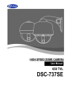
HIGH SPEED DOME CAMERA
- 27X OPTICAL ZOOM
- 37X OPTICAL ZOOM
USER MANUAL
If the product is to be put out of operation definitively, take it to a local
recycling plant for a disposal which is not harmful to the environment.
Please read the instructions carefully for correct use of the product and preserve it for
reference purposes. This specification is subject to change without any prior notice to
improve the quality.
<Chapter 1. Warning and Cautions>
1.1 FEATURES ............................................................................................................. 6
1.2 WARNING AND CAUTIONS ..................................................................................... 7
1.3 WARNING .............................................................................................................. 8
1.4 CAUTIONS ............................................................................................................. 9
<Chapter 2. Overview and How to install>
2.1 ACCESSORIES ...................................................................................................... 11
2.2 OVERVIEW 1 ........................................................................................................ 12
2.2.1 DIMENSION ............................................................................................................... 12
2.2.2 DESIGNATION ........................................................................................................... 13
2.2.3 CAMERA CONFIGURATION ...................................................................................... 14
2.3 OVERVIEW 2 ....................................................................................................... 17
2.3.1 TERMINAL CONFIGURATION .................................................................................... 17
2.4 HOW TO INSTALL ................................................................................................. 19
2.4.1 CONNECTING THE CABLE TO TERMINAL BLOCK .................................................. 19
2.4.2 SWITCH SETTING ..................................................................................................... 19
2.4.3 CAMERA INSTALLATION .......................................................................................... 20
2.5 SPECIFICATION ................................................................................................... 24
<Chapter 3. Menu configuration and operating >
3.1 PTZ CONTROL ..................................................................................................... 27
3.1.1 PRESET ..................................................................................................................... 27
3.1.2 MOTION DETECTION ................................................................................................ 29
3.1.3 AUTO SCAN .............................................................................................................. 31
3.1.4 SEQ SCAN ............................................................................................................... 33
3.1.5 RANDOM SCAN ...................................................................................................... 34
3.1.6 PATTERN SCAN ....................................................................................................... 35
3.1.7 TIME SCHEDULE ...................................................................................................... 36
3
3.2 TIME SET ............................................................................................................ 38
3.2.1 TIME SET SETTING .................................................................................................. 38
3.3 PRIVACY ZONE .................................................................................................... 39
3.3.1 PRIVACY MASK SETTING ........................................................................................ 39
3.4 ALARM IN ........................................................................................................... 41
3.4.1 ALARM IN SETTING ................................................................................................. 41
3.5 ALARM OUT ....................................................................................................... 42
3.6 SETUP ................................................................................................................ 43
3.6.1 CAMERA SETUP ...................................................................................................... 43
3.6.2 PAN/TILT SETUP ...................................................................................................... 47
3.6.3 DISPLAY SETUP ...................................................................................................... 49
3.6.4 AUTO PARKING ........................................................................................................ 51
3.7 SYSTEM .............................................................................................................. 52
3.7.1 REBOOT SYSTEM ..................................................................................................... 52
3.7.2 RESET ..................................................................................................................... 52
3.7.3 PASSWORD SET ..................................................................................................... 53
3.7.4 SYSTEM INFORMATION ........................................................................................... 54
4
Chapter 1.
Warning and Cautions
1.1 FEATURES ......................................................... 6
1.2 WARNING AND CAUTIONS ................ 7
1.3 WARNING .......................................................... 8
1.4 CAUTIONS
........................................................
9
Chapter 1. Warning and Cautions
1.1 FEATURES
1) High Speed
- This is the high speed dome camera which has wide speed range
(Min. 0.05deg/sec ~ Max. 400deg/sec)
- Speed is controlled by user's option or the zoom magnification.
2) Preset & Motion Detection
- A maximum of 128 preset positions and 8 tour functions can be set. It also
supports motion detection function.
3) Pattern
- This camera supports a maximum of 4 patterns which operate for 1 minute
~ 2 hours according to their complexity.
4) Time set & Schedule
- Inside the camera adopted RTC function and battery, it can be save &
display current time.
- Schedule enables you to schedule a sequencing action by day and time.
- A maximum of 8 schedule can be set.
5) Privacy Zone
- Area masking can be set up for up to 8 points. For privacy, this camera
provides a function for hiding the points for which area masking is
selected from screen.
6) Alarm input/Alarm output
- Sensor can connect to alarm input to detect motion from outside.
- Alarm output supports "relay out" and "Open collector output".
7) Digital Auto Flip
- For monitoring an object moving below a camera , by running Auto Flip,
moving objects can be monitored without screen reverse.
8) RS-485/422
- The function of the camera can be controlled by RS-485/422.
9) Mounting bracket for easy installation
- It is easy to install the camera by using the mounting bracket provided as
accessories.
6
Chapter 1. Warning and Cautions
1.2 WARNING AND CAUTIONS
Please carefully check these particulars for the safe use.
1.2.1 EXAMPLES OF SIGN
WARNING
This symbol indicates the cause of death or serious
injury to the user.
CAUTION
This symbol indicates the cause of equipment
damage.
1.2.2 EXAMPLES OF SIGN
This symbol indicates the warning of electric shock.
This symbol indicateds the prohibition of disassembly.
This symbol indicates to observe plug off.
7
Chapter 1. Warning and Cautions
1.3 WARNING
WARNING
Install the product on firm and durable position.
Use a recommended adaptor by the manual.
Unplug the unit when there is any sign of electric leakage,
short circuit or smog by burn.
Do not disassemble or remodel the product.
Please check the external terminal before connecting the
signal cables
8
Chapter 1. Warning and Cautions
1.4 CAUTION
Caution
This product should be installed by expert installer.
Do not install the product at the position exposed to the direct sun.
Do not install the product where lighting is unstable.
Do not drop, hit strongly nor vibrate the product.
Please use the product at the proper environment as follow.
- Temperature : 0℃ ~ 50℃(32℉ ~ 122℉)
- Humidity : below 90%
This product is produced only for the power as follow.
*Be sure to connect power after all installation are completed.
- Current consumption : 24V AC ±10%, Max 1.5A
- Power Consumption : 18W
Unplug it when any inflammable or conductive material
goes into the product.
9
Chapter 2.
Overview and How to install
2.1 ACCESSORIES ............................................. 11
2.2 OVERVIEW 1
................................................
12
2.3 OVERVIEW 2
................................................
17
2.4 HOW TO INSTALL
2.5 SPECIFICATION
....................................
........................................
19
24
Chapter 2. Overview and How to install
2.1 ACCESSORIES
FIXING SCREW : SCREW 4x25 Tp1 BIND BK, 3EA
ANCHOR : 6x30, 3EA
MOUNT BRACKET
CORE
ACCESSORY RING
TERMINAL BLOCK
TERMINAL 15EDGR-3.81 - 2P, FMALE
USER MANUAL
TERMINAL 15EDGR-3.81 - 3P, FMALE
TERMINAL 15EDGR-3.81 - 9P, FMALE
TERMINAL 15EDGR-3.81 - 10P, FMALE
11
Chapter 2. Overview and How to install
2.2 OVERVIEW 1
2.2.1 Dimension
Ø220
Ø150
Ø161
12
Chapter 2. Overview and How to install
2.2.2 Designation
MOUNTING BRACKET
ACCESSORY RING
TERMINAL PART
BODY PART
DOME COVER
13
Chapter 2. Overview and How to install
2.2.3 Camera configuration
①ADDRESS switch
- It is to set camera ID to connect multiple cameras.
- Max. 255 of camera IDs(as binary notation) are available.
- Camera ID setting is as described on <Table. 5>.
②PROTOCOL switch
- Protocol can be set manually or automatically.
- Upon selecting "Protocol Auto Detection" function, protocol will be selected automatically.
- PROTOCOL setting is as described on <Table.1>.
③BAUDRATE switch
- Select baud rate.
- Baud rate setting is as described on <Table 2>.
④RS-422/RS-485 switch
- RS-422 or RS-485 is selectable for remote control between camera and controller.
- RS-422/RS-485 switch setting is as described on <Table 3>.
⑤TERMINATION switch : Used for RS-485/RS-422 connection
- ON : Set on the last camera for 1:1 or multi communication between Camera and
PC or a controller.
- OFF : Set on all cameras except for the last camera for multi-communication.
- TERMINATION setting is as described on <Table 4>.
⑥SAFETY FUSE : It prevents overflow of electricity for safety.(250V, 3A)
⑥
"A"
①
⑤
③
②
DETAIL "A"
[Pic 1] DIP SWITCH
14
④
Chapter 2. Overview and How to install
Protocol
SW1
SW2
Auto
OFF
OFF
SK-P
ON
OFF
Pelco-D
OFF
ON
[Table 1] PROTOCOL SETTING
Baudrate
SW3
SW4
2400 bps
OFF
OFF
4800 bps
ON
OFF
9600 bps
OFF
ON
19200 bps
ON
ON
[Table 2] BAUDRATE SWITCH
Communication
SW6
RS-485
OFF
RS-422
ON
[Table 3] RS485 / 422 SETTING
Termination
SW7
SW8
ON
ON
OFF
OFF
ON
ON
[Table 4] TERMINATION SETTING
Camera ID
1
2
3
4
5
6
7
8
9
SW1
ON
OFF
ON
OFF
ON
OFF
ON
OFF
ON
SW2
OFF
ON
ON
OFF
OFF
ON
ON
OFF
OFF
SW3
OFF
OFF
OFF
ON
ON
ON
ON
OFF
OFF
15
SW4
OFF
OFF
OFF
OFF
OFF
OFF
OFF
ON
ON
SW5
OFF
OFF
OFF
OFF
OFF
OFF
OFF
OFF
OFF
SW6
OFF
OFF
OFF
OFF
OFF
OFF
OFF
OFF
OFF
SW7
OFF
OFF
OFF
OFF
OFF
OFF
OFF
OFF
OFF
SW8
OFF
OFF
OFF
OFF
OFF
OFF
OFF
OFF
OFF
Chapter 2. Overview and How to install
10
11
12
13
14
15
16
17
18
19
20
21
22
23
24
25
26
27
28
29
30
31
32
33
34
35
36
37
38
39
40
41
42
43
44
OFF
ON
OFF
ON
OFF
ON
OFF
ON
OFF
ON
OFF
ON
OFF
ON
OFF
ON
OFF
ON
OFF
ON
OFF
ON
OFF
ON
OFF
ON
OFF
ON
OFF
ON
OFF
ON
OFF
ON
OFF
ON
ON
OFF
OFF
ON
ON
OFF
OFF
ON
ON
OFF
OFF
ON
ON
OFF
OFF
ON
ON
OFF
OFF
ON
ON
OFF
OFF
ON
ON
OFF
OFF
ON
ON
OFF
OFF
ON
ON
OFF
OFF
OFF
ON
ON
ON
ON
OFF
OFF
OFF
OFF
ON
ON
ON
ON
OFF
OFF
OFF
OFF
ON
ON
ON
ON
OFF
OFF
OFF
OFF
ON
ON
ON
ON
OFF
OFF
OFF
OFF
ON
ON
ON
ON
ON
ON
ON
OFF
OFF
OFF
OFF
OFF
OFF
OFF
OFF
ON
ON
ON
ON
ON
ON
ON
ON
OFF
OFF
OFF
OFF
OFF
OFF
OFF
OFF
ON
ON
ON
ON
ON
OFF
OFF
OFF
OFF
OFF
OFF
ON
ON
ON
ON
ON
ON
ON
ON
ON
ON
ON
ON
ON
ON
ON
ON
OFF
OFF
OFF
OFF
OFF
OFF
OFF
OFF
OFF
OFF
OFF
OFF
OFF
ㆍ
ㆍ
The rest is omitted.
[Table 5] CAMERA ID SETTING
16
OFF
OFF
OFF
OFF
OFF
OFF
OFF
OFF
OFF
OFF
OFF
OFF
OFF
OFF
OFF
OFF
OFF
OFF
OFF
OFF
OFF
OFF
ON
ON
ON
ON
ON
ON
ON
ON
ON
ON
ON
ON
ON
OFF
OFF
OFF
OFF
OFF
OFF
OFF
OFF
OFF
OFF
OFF
OFF
OFF
OFF
OFF
OFF
OFF
OFF
OFF
OFF
OFF
OFF
OFF
OFF
OFF
OFF
OFF
OFF
OFF
OFF
OFF
OFF
OFF
OFF
OFF
OFF
OFF
OFF
OFF
OFF
OFF
OFF
OFF
OFF
OFF
OFF
OFF
OFF
OFF
OFF
OFF
OFF
OFF
OFF
OFF
OFF
OFF
OFF
OFF
OFF
OFF
OFF
OFF
OFF
OFF
OFF
OFF
OFF
OFF
OFF
Chapter 2. Overview and How to install
2.3 OVERVIEW 2
2.3.1 Terminal configuration
①POWER TERMINAL : Use AC24V ±10%, Max 1.5A
②AUX2 : ALARM OUTPUT(OPEN COLLECTOR)
③AUX1 : ALARM OUTPUT(RELAY)
④RX+/RX- :
- Terminal for receiving the data on RS-422 communication.
- Terminal for data communication on RS-485.
⑤TX+/TX- : Terminal for transporting the data on
RS-422 communication.
⑥VIDEO+/- : For video signal output.
⑦SENSOR 1/2/3/4/5/6/7/8 : For alarm input.
[Pic 2] TERMINAL PART
⑦
"B"
"C"
①
②
③
④
⑤
⑥
Detail "B"
Detail "C"
RS-485 CABLE
Open the CORE as
the followed picture.
Wind RS-485 cable
on the CORE one time.
[Pic 3] TERMINAL BLOCK
17
Close the CORE.
Chapter 2. Overview and How to install
1
POWER
(AC 24V, 1.5A)
2
AC 24V
3
External
1
2
NC
3
COM
4
NO
5
ALARM OUT
(5V, Logic)
RELAY
(AC 120V, 2A. DC 24V )
6
Half Duplex Type A(+)
7
Controller
B(-)
8 Rx -
Full Duplex Type Rx(+)
9 Tx +
10 Tx -
Controller
Rx +
CONTROLLER INTERFACE
RS-422 / RS-485
Rx(-)
Tx(+)
Tx(-)
1
VIDEO +
2
VIDEO -
VIDEO OUT
1
ALARM OUT
sensor1
2
sensor2
3
sensor3
4
sensor4
5
GROUND
6
sensor5
7
sensor6
8
sensor7
9
sensor8
[Pic 4] TERMINAL BLOCK DIAGRAM
18
Chapter 2. Overview and How to install
2.4 HOW TO INSTALL
2.4.1 Connecting the cable to terminal block.
Please refer to [Pic. 3&4] for the connection.
[Pic 5] INSTALLATION 1
2.4.2 Switch setting
Please refer to [Table 1~5] for switch setting.
19
Chapter 2. Overview and How to install
2.4.3 Camera installation
2.4.3.1 Remove the protective sheet from the inner dome.
1) Pull out the outer dome cover.
2) Remove the protective sheet from the inner dome.
3) Twist the outer dome cover clockwise.
※Remove the protective sheet of the outer dome cover before operating camera.
Protective sheet
Outer dome cover
Protective
sheet
Inner dome
[Pic 6] FIXED DOME COVER
2.4.3.2 Separate terminal part from body part.
1) Loosen the fixing screw on the bottom of the body.
2) Turn the body part clockwise and pull the terminal part.
Terminal part
Fixing screw
Body part
[Pic 7] SEPARATION
20
Chapter 2. Overview and How to install
2.4.3.3 Mount the terminal part on the ceiling.
Fixing screw 4x35
Mount bracket
Terminal part
1) Make a hole of 90 ~ 110mm in diameter.
2) Using the mounting bracket as a template drill three holes in the ceiling to
mount the bracket.
3) Fasten three screws to fix the terminal
part on the ceiling.
<Caution> Don't block the ventilation hole.
It may cause malfunction.
Anchor 6x30
[Pic 8] USING SAFETY WIRE
2.4.3.4 Use the safety wire to prevent the camera from falling.
1) Pull the wire on the bottom of the body
part.
2) Hook the wire over the terminal part
as followed picture.
3 hasps for safety wire
Safety wire
[Pic 9] INSTALLATION TERMINAL PART
2.4.3.5 Connect the terminal block
1) Open the cover of the terminal part to connect terminal block.
<Caution> Be sure to connect power after all installation are completed.
2) Refer to terminal block diagram for connection.(Pic.6&7)
3) Close the cover of the terminal part and fasten the screw.
21
Chapter 2. Overview and How to install
2.4.3.6 Address and Setup switch setting
1) Set the switch on the bottom of the body part.
2) Refer to [Table 1~5] for switch setup.
3) Check if D-SUB Connector"Open".
D-SUB CONNECTOR
POSITION CHECK
[Pic 10] SWITCH SETUP
2.4.3.7 Restore the safety wire
1) Restore the satety wire to the original position.(Push the wire to the wire hole.)
[Pic 11] SAFETY WIRE
22
Chapter 2. Overview and How to install
2.4.3.8 Combine the terminal part and body part
1) Place the summit of a triangle on the body part to the center of "U" groove on the
terminal part.
2) Turn the body part clockwise.
3) Fasten the fixing screws on the body part.
Match the summit of a triangle to the
center of U type groove.
Fixing screw
[Pic 12] SWITCH SETUP
2.4.3.9 Combine the bottom ring
1) Combine two parts of the bottom ring at the bottom of the body part.
2) Place the square groove to logo of the body part as followed picture and turn the
ring anticlockwise.
Match the logo in a single file.
[Pic 13] COMBINE RING
23
Chapter 2. Overview and How to install
2.5 SPECIFICATION
Item
Specification
Type 2
Type 1
Zoom
CCD
27X Optical, 16X Digital
TV Type
Effective Pixel
Resolution
Min. Illumination
Focal Length
37X Optical, 16X Digital
1/4" COLOR SONY SUPER HAD CCD
NTSC, PAL
768(H) X 494(V) PIXEL(NTSC), 752(H) X 582(V) PIXEL(PAL)
Color : 600 TV-Line, B/W : 700 TV-Line
Color : 0.2Lux/F1.6(50IRE), B/W : 0.02Lux/F1.6(50IRE)
f = 3.5 ~ 95mm
Day&Nighit
f = 3.5 ~ 129.5mm
ICR(AUTO/COLOR/BW)
Preset
128points
Pattern
4patterns(210sec ~ 2 hours : depends on complexity)
Privacy Zone
8zones
Tour
8tours
Auto Scan
CW/CCW/Custom mode
Pan Angle
360deg(Endless)
Tilt Angle
180deg(Auto Flip)
Pan/Tilt Speed
0.05 ~ 120deg/sec(Manual), Max. 400deg/sec(Preset)
Alarm Input
Alarm Output
8
Open Collector(5V DC, 40mA) / Relay(30V DC, 2A / 125V AC, 0.5A)
Address(ID)
255
Remote Control
RS-485 or RS-422
Protocol
AUTO, SK-P, PELCO-D
Power
24V AC / 18W 1.5A
Operation Temp.
0℃ ~ 50℃
Preservation Temp.
-20℃ ~ 60℃
Dimension
Ø150mm X 252mm
Approx. 2.2Kg
Weight
Bracket(option)
SK-AB04, AB05, AB06, Ab07
24
Chapter 3.
Menu configuration
and operating
3.1 PTZ CONTROL ........................................... 27
3.2 TIME SET ....................................................... 38
3.3 PRIVACY ZONE ......................................... 39
3.4 ALARM IN ....................................................... 41
3.5 ALARM OUT
3.6 SETUP
...............................................
42
..............................................................
43
3.7 SYSTEM
...........................................................
52
Chapter 3. Menu configuration and operating
Not only basic function such as Pan/Tilt/Zoom but additional functions are available for this
camera. Additional functions are as follow.
PRESET
Setting functions of speed dome such as Preset and Motion
detection
MOTION CONTROL
Setting function of speed dome such as Sequence/Random
Scan, Custom/CW/CCW Scan and Pattern/Schedule
TIME SET
Set current time
PRIVACY ZONE
Hide the points for which area masking is selected from the
screen
ALARM IN
Set regarding sensor input
ALARM OUT
Set operation of the connected sensor
SETUP
Set up for camera, motor and display
SYSTEM
System setting such as Password, Reboot, Reset and System
Information
SCHEDULE
Schedule enables you to schedule a sequencing by day and
time.
These functions are set on OSD.
OSD menu setup by the specialty controller
1) MENU : Press "MENU" button to go to the menu(P/T/Z function would be stopped.)
2) IRIS OPEN : Move to the sub menu or select the menu.
3) IRIS CLOSE : Move to the above menu or move the cursor to "EXIT"
4) Joystick
ㆍRight: Move the cursor to the right or the sub menu.
ㆍLeft: Move the cursor to the left or the previous menu.
ㆍUP: Move the cursor to the above or increase the value.
ㆍDown: Move the cursor to the below or decrease the value.
26
Chapter 3. Menu configuration and operating
This is first page of the OSD menu.
MAIN MENU -------------------------------Preset
Motion Control
Time Set
Privacy Zone
Alarm In
Alarm Out
Setup
System
Exit
3.1 PTZ CONTROL
3.1.1 PRESET(Path : MAIN MENU / PRESET)
This function is to save, delete, or call the specific position of Pan, Tilt, Zoom or Focus
by user's option.
PRESET ------------------------------------Number:
Name:
Dwell Time:
Speed:
Group:
Edit Position
Motion Detection
Clear
Set
Back
001*
PRESET
005
20
1
3.1.1.1 SAVE PRESET POSITION
1) Number : Change the number on "NUMBER".(If you already set the number, the
camera would move to the saved position.)
2) Name : Press "IRIS OPEN" or "MENU" button of the controller to set the name of preset.
3) Dwell Time : Set staying time in each position for preset.(Default : 5sec, The range
is 1~250.)
27
Chapter 3. Menu configuration and operating
ID SETUP -----------------------------------ABCDEFGHIJKLMNOPQRSTUVYXYZ
abcd efgh i jklmn o pqrs tuv wx y z
1 234 5 67 8 9 0
+ - 4 / ! # * ~, . : - ~ < > [] $ % &
<<
>>
Del
Clear
Display:[…………………………………]
Set
Back
4) Speed : Set the moving speed to preset position.(The range of speed is 1~20)
5) Group : Set the group number of SEQ SCAN function.
6) Edit Position : To change PTZ of the preset position.
7) Motion & Detection : Motion detection is compatible with preset.(Please refer to
3.1.2 "MOTION DETECTION")
8) Clear : This is to delete one or all preset position.
CLEAR PRESET --------------------------Number:
‘Press Enter To Erase’
001*
Clear All
BACK
9) Set : Save current value. If you don't run "set", the value will not save. After saving
is completed, The " * " appeared beside number.
3.1.1.2 CALL THE PRESET POSITION
1) Input the preset number you want to move on "NUMBER".
2) Incase " * " appears at the right of the number, press "IRIS CLOSE" button.
[TIP] With special controller(option), you can use "PRESET" function easily.
28
Chapter 3. Menu configuration and operating
3.1.2 MOTION DETECTION(Path : MAIN MENU / PRESET / MOTION DETECTION)
This is the sub menu for preset. You can set eight specific zones on the screen and
upon detection of motion on the zones, the camera would operate as what you set.
MOTION DETECT -------------------------AUX Active:
Dome Action:
Sensitivity:
AUX1
Off
1
Edit Area
Set
Back
3.1.2.1 MOTION DETECTION SETTING
1) AUX Active :
ㆍOff : No action.
ㆍAUX1 : Relay upon detection of motion.
ㆍAUX2 : Activate output of "Open collector".
2) Dome Action :
ㆍOff : No action.
ㆍPTRN1 ~ PTRN4 : The camera move as PTRN1~PTRN4 upon detection of motion.
ㆍCW : Scan clockwise automatically upon detection of motion.
ㆍCCW : Scan counterclockwise automatically upon detection of motion.
ㆍCUSTOM : Patrol the area set by the user on "Custom set".
3) Sensitivity : Set the sensitivity of detecting motion. Higher number means higher sensitivity.
Please set the proper sensitivity to prevent from operating abnormally.
High sensitivity may cause malfunction of the camera.
4) Edit Area : You can set the maximum of 4 zones as follow.
29
Chapter 3. Menu configuration and operating
EDIT AREA --------------------------------Zone Enable
├ Zone1:
├ Zone2:
├ Zone3:
└ Zone4:
Off
Off
Off
Off
Set Position
Back
3.1.2.2 MOTION DETECTION AREA SETTING
1) Zone Enable : Select 4 Motion Detection Zones On/Off
2) Set Position : Set the position and size the selected zone.
Zone1(Red)
Zone1(Red)
Decide To Left Top.
Move P/T Command & Press
Iris Open Or Enter.
Decide To Right Top.
Move P/T Command & Press
Iris Open Or Enter
: ①Move to where you want place as shown on the picture. After that press the IRIS
OPEN or MENU key to move next step.
②Set the size of zone as shown on the right picture. After that press the IRIS OPEN
or MENU key.
30
Chapter 3. Menu configuration and operating
3.1.3. AUTO SCAN(Path : MAIN MENU / MOTION CONTROL / AUTO SCAN)
This function is to make the camera panning automatically at the fixed speed.
"TILT" or "ZOOM" function can be set by user's option on AUTO SCAN mode.
<Notice> Move joystick to the right or the left to stop AUTO SCAN mode but after few seconds the auto
scan action again. If you want to stop this function, send "STOP" command by the controller.
AUTO SCAN -------------------------------Scan Mode:
Scan Speed:
Custom
01
Custom Set
Run Auto Scan
Back
Exit
3.1.3.1 AUTO SCAN SETTING
1) Scan Mode :
ㆍCW : Clockwise Auto scan
ㆍCCW : Counterclockwise Auto scan.
ㆍCustom : Patrol the area set by the user on "CUSTOM SET"
2) Scan Speed : Max. 20 levels are selectable. Higher number means higher speed.
Default value is "5"
3) Custom Set : Limits the range of movement in the PAN direction. Determine the
left/ right end position using the joystick and press "IRIS OPEN" or "MENU" key to
complete custom set.
31
Chapter 3. Menu configuration and operating
Move Pan To Set R. Position
Press Iris Open Or Menu
Move Pan To Set L. Position
Press Iris Open Or Menu
4) Run Auto Scan : Start the Auto scan by user setting mode.
<Notice> Move the joystick to stop the auto scan, after few seconds the auto scan again.
Send the command of Auto Scan Stop or menu key to move out the Auto scan.
32
Chapter 3. Menu configuration and operating
3.1.4 SEQ SCAN(Path : MAIN MENU / MOTION CONTROL / SEQ SCAN)
This function is to move the camera to the memorized positions one by one.
SEQ SCAN ---------------------------------Seq Group:
1
Run Seq Scan
Back
Exit
3.1.4.1 SEQ SCAN SETTING
1) Seq Group : The camera moves to the memorized positions one by one according
to the group. Please refer to [3.1.1 PRESET] to set group. Max. 8 groups are
available.
2) Run Seq Scan : Run SEQ SCAN by user set group.
<Notice> Move the joystick to stop the seq scan, after few seconds the seq scan again.
Send the command of Sequential Scan Stop or menu key to move out the Sequential scan.
33
Chapter 3. Menu configuration and operating
3.1.5 RANDOM SCAN(Path : MAIN MENU / MOTION CONTROL / RANDOM SCAN)
This function is to move the camera to the memorized positions randomly.
RANDOM SCAN -------------------------Random Group:
1
Run Random Scan
Back
Exit
3.1.5.1 RANDOM SCAN SETTING
1) Random Group : Register up to 8 groups. The camera move s to the memorized
positions randomly according to the group. Please refer to "4.1 PRESETS" to set
group.
2) Run Random Scan : Run random scan user set group
<Notice> Move the joystick to stop the auto scan, after few seconds the auto scan again.
Send the command of Random Scan Stop or menu key to move out the Random scan.
34
Chapter 3. Menu configuration and operating
3.1.6 PATTERN SCAN(Path : MAIN MENU / MOTION CONTROL / PATTERN SCAN)
This function is to memorize the position by panning, tilting , or zooming for a while and
move the camera to the memorized positions. Save up to 4 patterns .
"PATTERN SCAN" repeats until user moves joystick or press "STOP" on the controller.
<Notice> Pattern Scan Setting / Playback, AUTO FLIP feature is automatically disabled.
PATTERN SCAN --------------------------Pattern Num:
1
Start Pattern Learn
Run Pattern
Back
Exit
3.1.6.1 PATTERN SCAN SETTING
1) Pattern Num : Set pattern number.(1~4) Default value is 1.
2) Start Pattern Learn : Start Pattern Learn : To move P/T/Z to memorize pattern.
Press IRIS OPEN Or Menu To Stop
Memory Left:
000
: Memory Left - Display the available number of memory.
3) Run Pattern : Run pattern.
<Notice> Move the joystick to stop the pattern scan, after few seconds the pattern scan again.
Send the command of pattern Stop or menu key to move out the pattern scan.
35
Chapter 3. Menu configuration and operating
3.1.7 TIME SCHEDULE(Path : MAIN MENU / MOTION CONTROL / TIME SCHEDULE)
Schedule enables you to schedule a sequencing by day and time. Up to 8 timeline
can be selected for a day.
TIME SCHEDULE ------------------------Number:
Enable:
1
Off
Start Time:
End Time:
Time Act:
00:00
00:00
SEQ1
Set
Back
Exit
3.1.7.1 TIME SCHEDULE SETTING
1) Number : Select number of schedule. Up to 8 timeline can be selected for a day.
Default value is 1.
2) Enable : Determine whether to use this function or not.
3) Start Time : Set start time. Press the IRIS OPEN or MENU key to select hour and
then press again the IRIS OPEN or MENU key to select minute. After that you
should press the 'IRIS CLOSE' key to escape this menu.
4) End Time : Set end time.
5) Time Act : Select the sequencing action to schedule the action.
ㆍOFF : No action.
ㆍPTRN 1~4 : The camera move as PTRN1~PTRN4.
ㆍSEQ 1~8 : The camera move as SEQ1~SEQ8.
ㆍCW : Scan clockwise automatically.
ㆍCCW : Scan counterclockwise automatically.
ㆍCustom : The camera working Auto Scan mode by custom mode.
6) Set : Set : Save the value and then move out this menu.
36
Chapter 3. Menu configuration and operating
TIME TABLE -------------------------------No
1.
2.
3.
4.
5.
6.
7.
8.
Ena
On
Off
Off
Off
Off
Off
Off
Off
Act
Custom
SEQ3
SEQ3
SEQ3
SEQ3
SEQ3
SEQ3
SEQ3
Start
End
13:30 ~ 14:55
00:00 ~ 00:00
00:00 ~ 00:00
00:00 ~ 00:00
00:00 ~ 00:00
00:00 ~ 00:00
00:00 ~ 00:00
00:00 ~ 00:00
Press Menu To Exit
: When turning ON this menu, the timetable appears as shown on the picture.
37
Chapter 3. Menu configuration and operating
3.2 TIME SET(Path : MAIN MENU / TIME SET)
Customize the camera clock; you can schedule sequence actions to perform
automatically.
<Notice> If the time error occurs, you should replace the battery in the camera.
TIME SET ----------------------------------Time Format:
Date Format:
Format Save
24H
yy/dd/mm
Time Set:
Date Set:
Time Save
00:00:00
00/00/00
Back
Exit
3.2.1 TIME SET SETTING
1) Time Format : Change the display format of the camera time 24H or 12H.
<Notice> Time set 12hours/24hours will be affected only on a screen. The function of "Time set"
and "Time schedule" you must set 24 hours standard.
2) Date Format : Change the display format of the camera date.(DD/MM/YYYY or
MM/DD/YYYY)
3) Format Save : Save the display format of the camera date and time.
4) Time Set : Enter a time.
5) Date Set : Enter a date.
6) Time Save : Save current value.
38
Chapter 3. Menu configuration and operating
3.3 PRIVACY ZONE(Path : MAIN MENU / PRIVACY ZONE)
For privacy, this camera provides a function for hiding the points for which area
masking is selected from screen. Area masking can be set up for up to 16 points.
Setting up more than 5 points may cause masks to move slow.
<Notice> In case of saving zones with auto-flip condition, auto-flip will be released.
PRIVACY ZONE --------------------------Zone Number:
Display
01
Off
Mask Adjust
Mask Color
Clear Mask
Gray
Back
Exit
3.3.1 PRIVACY MASK SETTING
1) Zone Number : Up to 16 points.
2) Display : To determine whether to be privacy zone visible.
3) Mask Adjust : Set the position and size the selected privacy zone.
①Please move to where you want place as shown on the ① picture. After that press
the IRIS OPEN or MENU key to move next step.
②Set the size of privacy zone as shown on the ② picture. After that press the IRIS
OPEN or MENU key to move next step.
③Set the position of privacy zone as shown on the ③ picture. After that press the
IRIS OPEN or MENU key to finish this function.
4) Mask Color : To change the color of Privacy zone. 5 color are selectable.(Gray/Blue/
Red/Black/White)
5) Clear Mask : Delete the set mask.
39
Chapter 3. Menu configuration and operating
①
②
Decide To Mask Size
INC: ↑→ DEC: ↓←
Move To Adjust Position
Move : P/T/Z Command
③
Decide To Mask Position
Move: P/T Command
40
Chapter 3. Menu configuration and operating
3.4 ALARM IN(Path : MAIN MENU / ALARM IN)
This function is to activate alarm upon detection of sensor..
ALARM IN ---------------------------------Sensor Num:
Priority:
Input Contact:
Activate
├ AUX:
├ Preset:
└ Dome Act:
Set
Back
Exit
1
1
Off
Off
Off
Off
3.4.1 ALARM IN SETTING
1) Sensor Num : Set the alarm numbers up to 8 numbers. Please refer to Pic.3 Terminal
configuration for alarm input.
2) Priority : Set the priority of 8 alarm inputs and react to the alarm input in accordance
with the priority.
Lower number means higher priority. Operation by the alarm with higher priority
takes precedence over the alarm with lower priority. In case of the alarms with the
same priority, the camera would be operated by the alarm in turns. On operating
by the alarm with higher priority, the alarm with lower priority would be ignored.
3) Input Contact : Set according to the connected sensor.
ㆍOff : "No sensor" connected
ㆍN.O : "Normally Open"
ㆍN.C : "Normally Closed"
<Notice> In case there is no sensor connected, please set "OFF", otherwise it might cause
malfunction.
4) Activate : Set "On" to activate "ALARM", "PRESET" or "DOME ACTION". Operation by
"PRESET" would be just one time, and after that, operation by "DOME ACTION"
would repeat.
ㆍAUX : Enables selecting an alarm output method.(Off/1/2) Off is not support alarm
output. 1 is Relay. 2 is Open collector.
ㆍPreset : Enables setting up a Preset action.
ㆍDome Action : Enables setting up a Dome action.
41
Chapter 3. Menu configuration and operating
3.5 ALARM OUT(Path : MAIN MENU / ALARM OUT)
To set the output against the alarm input.
ALARM OUT ------------------------------AUX1 Set
├ Mode:
└ Dwell Time:
AUX2 Set
├ Mode:
└ Dwell Time:
Off
05
Off
05
Set
Back
Exit
1) Mode :
ㆍOff : No action.
ㆍP_Act : Output until canceling the alarm regardless dwell time.(Permanent activation)
ㆍM_Act : Output for dwell time.(Momentary activation)
2) Dwell Time : Set dwell time from 1 to 60 sec
42
Chapter 3. Menu configuration and operating
3.6 SETUP(Path : MAIN MENU / SETUP)
This is setup for camera function such as display, Pan/Tilt and etc.
SETUP --------------------------------------Language :
English
Camera Setup
Pan/Tilt Setup
Display Setup
Auto Parking
Back
Exit
: The camera supports multi-language..
<Notice> The language might be different according to the F/W.
3.6.1 CAMERA SETUP(Path : MAIN MENU / SETUP / Camera Setup)
Set the camera's option.
CAMERA SETUP ----------------------
CAMERA SETUP ----------------------
DZoom Limit :
Day&Night :
SSDR :
Backlight :
White Balance :
-Manual Red :
-Manual Blue :
Brightness :
AGC :
SSNR :
Shutter :
Senseup :
Saturation :
Sharpness :
Sync :
-Phase :
Focus Set :
Reverse :
DIS Mode :
Back
Off
Auto
On
BLC
AWC
128
129
015
Low
Off
Auto
Off
015
010
L.L
154
Auto
Off
Off
Off
: The page of menu is seperated as 2 pages. You can move to next page on the end
of first page.
1) DZoom Limit : Enables the maximum digital zoom.(Off ~ 16X)
2) Day&Night : The Day & Night function allows the camera to switch between the
Color and B/W modes.
43
Chapter 3. Menu configuration and operating
ㆍAuto : The picture switches automatically color to B/W as the light level changes.
ㆍNight : The picture switches to B/W.
ㆍColor : The picture switches to color.
3) SSDR : SSDR illuminates darker spots of an image while retaining the same light
level for brighter spots to even out the overall brightness of the image with high
contrast between bright and dark spots.(On/Off : Enables or disables SSDR.)
ㆍRange : Defines a range of SSDR.(Narrow / Wide)
ㆍLevel : Changes the contrast between bright and dark spots by the level.(00~15)
SSDR SETUP -----------------------------Range :
Level :
Wide
15
Save&Back
Back
4) Backlight : This camera is designed to deliver a distinctive subject and background
at the same time, even when the subject is backlight.
ㆍOff : Disables this function
ㆍBLC : Enables a user to directly select a desired area from a picture, and to view
the area more clearly.
USER BLC SETUP -----------------------Mode :
Level :
On
Low
Top :
Bottom :
Left :
Righjt :
025
025
025
025
Save&Back
Back
44
Chapter 3. Menu configuration and operating
- Mode : Activate / Deactivate BLC
- Level : Adjust the level
- Top : Determines the upper end of BLC area is to be used.(000 ~ 100)
- Bottom : Determines the lower end of BLC area is to be used.(000 ~ 100)
- Left : Determines the left end of BLC area is to be used.(000 ~ 100)
- Right : Determines the right end of BLC area is to be used.(000 ~ 100)
ㆍHLC : If the scene contains extremely bright light areas such as; from car headlight,
the light can mask out much of the on-screen detail.
USER HLC SETUP -----------------------Mode :
Level :
Color :
On
Low
10
Save&Back
Back
- Mode : Enables or disables HLC.
- Level : Adjust level of the HLC function.(LOW / MIDDLE / HIGH)
- Color : Change the color of highlight mask.(00 ~ 15)
5) White Balance : The White Balance menu adjusts the balance of the screen colors
under different lighting conditions.
ㆍATW/IN : Adjusts the screen color to be optimal in an indoor environment.
ㆍATW/OUT : Adjusts the screen color to be optimal in an outdoor environment.
ㆍAWC : To obtain the optimal condition for the current lighting, put the focus of the
camera to a white paper and press the SET button. If the lighting environment is
changed, you should readjust the settings accordingly.
ㆍMANUAL : Select this to fine-tune White Balance manually. Enables customization
the Red and Blue gains.
6) Brightness : Adjusts the screen brightness.(0 ~ 100)
7) AGC : AGC(Automatic Gain Control) adjusts the camera's gain control and the
screen brightness if the camera has captured an object under low-light conditions.
(Low / Medium / High / Manual)
If user choose the 'Manual' mode, user can adjust gain value(00 ~ 36)
45
Chapter 3. Menu configuration and operating
8) SSNR : SSNR significantly reduces the amount of low luminance noise.(Off / Low /
Middle / High)
9) Shutter : Control image brightness by adjusting shutter speed.
ㆍESC : Automatic shutter speed setting.(optimal)
ㆍAnti_FLK : Flicker-free mode.(NTSC : 1/100, PAL : 1/120)
ㆍMANUAL : Manual shutter speed setting.(1/60 ~ 512X)
10) Sense Up : Automatically detects light levels and maintains a clear picture at night
or under low-light conditions. The user can configure the SENS-UP limit by
increasing/decreasing the shutter speed(e.g. : X2, X4....... X32, X64, X128, X256,
X512).
11) Saturation : Control image saturation.(000 ~ 100)
12) Sharpness : Sharpness level adjustable.(00 ~ 30)
13) Sync : This function is to select video sync. The Internal and Line Lock modes are
available.
ㆍPhase : Control the Phase of the image.
14) Reverse : Flip the image horizontally, vertically or both on the screen.
15) Focus Set : You can select the most suitable zoom mode
ㆍAuto : The focus automatically adjusts when the lens zooms in and out.
ㆍManual : Changes the camera mode to Manual Focus.
ㆍZ.Trigg : Auto-focuses the camera once after the Zoom function is used.
16) DIS Mode : Compensates for any small movements of the camera caused by due
to the wind and other reasonable causes.(On / Off)
46
Chapter 3. Menu configuration and operating
3.6.2 PAN/TILT SETUP(Path : MAIN MENU / SETUP / PAN/TILT SETUP)
This is to set the functions related to PAN/TILT.
PAN/TILT SETUP ------------------------Auto Flip:
Prop.Pan:
Preset Freeze:
Manual Stop Limit:
└ Limit Set
Set Front
Power On Act:
Tilt Offset:
Back
Exit
On
On
Off
Off
Off
01
1) Auto Flip : For monitoring an object moving below a camera , by running Auto Flip,
moving objects can be monitored.
2) Prop.Pan(Proportional Pan) : Pan and tilt speed compensation function linked to
zoom position allows fine manual operation even during zooming.
3) Preset Freeze : On running preset function, the previous preset position will be shown
until the camera reaches a specified preset position to reduce the unnecessary
memories and to show clean pictures.
4) Manual Stop Limit : To activate "MANUAL STOP LIMIT".
Move Pan To Set Left Limit
Press Iris Open Or Menu
Move Pan To Set Right Limit
Press Iris Open Or Menu
: Manual stop limit set - Set the limit of panning range.
47
Chapter 3. Menu configuration and operating
5) Set Front : To memorize the front of the camera.
Move P/T/Z To Set Position
Press Iris open To Set
Press Iris Close To Cancel
: Move P/T/Z to set front direction and then press the IRIS OPEN key to finish the setup.
6) Power On Act : Set the program to operate when the camera turns on.
7) Tilt Offset : Tilt range would be limited by the setting degree at both end.
48
Chapter 3. Menu configuration and operating
3.6.3 DISPLAY SETUP(Path : MAIN MENU / SETUP / DISPLAY SETUP)
Set the displays of camera name, camera address, preset label or zoom label.
DISPLAY SETUP -------------------------Cam Name>
Cam Name Disp:
Cam ADDR Disp:
Preset Label Disp:
Zoom Label Disp:
Clock Display:
Set Positions
SPEED.DOME.CAM
On
On
LBL+NUM
On
On
Back
Exit
1) Cam Name : Set or change the camera name.
ID SETUP -----------------------------------ABCDEFGHIJKLMNOPQRSTUVYXYZ
a bcd efghi j klmno pqrs t uv wx y z
1 234 5 67 89 0
+ - 4 / ! # * ~ , . : - ~ <> [] $ % &
<<
>>
Del
Clear
Display:[…………………………………]
Set
Back
: Max. 14 characters are available. Default name is 'SPEED.DOME.CAM'
2) Cam Name Disp : Determines whether to display the camera ID.
3) Cam ADDR Disp : Determines whether to display the camera's address.
4) Preset Label Disp : Select the position of preset name and whether preset name
displays or not.
5) Zoom Label Disp : Select the position of the zoom magnification and whether
magnification of zoom displays or not.
6) Clock Display : Determines whether to display the time and date.
49
Chapter 3. Menu configuration and operating
7) Set Positions : Move joy stick left or right to select the position of label and press
"IRIS OPEN" button to confirm.
ADD SPEED.DOME.CAM
P.NAME
DATE DSP
TIME DSP
XZOOM
: Setting a positon of ID in order of precedence(Cam Name → Cam Addr → Preset
Name → Zoom → Date → Time).
Press the IRIS OPEN or MENU key to move next step.
50
Chapter 3. Menu configuration and operating
3.6.4 AUTO PARKING(Path : MAIN MENU / SETUP / AUTO PARKING)
If auto parking is set to ON, the camera runs assigned funtion automatically if there is
no PTZ command during assigned dwell time.
AUTO PARKING --------------------------A.P ON/OFF
A.P Dwell
A.P RUN
ON
001
RETURN
Back
Exit
1) A.P ON/OFF : Auto parking function activate / deactivate
2.) A.P Dwell : Set the waiting time
3) A.P Run : Select the action to run with the passing of dwell time.(Return / Preset 1~5)
51
Chapter 3. Menu configuration and operating
3.7 SYSTEM(Path : MAIN MENU / SYSTEM)
Set the camera's option.
SYSTEM ------------------------------------Reboot System
Reset
Password Set
├ Lock Enable:
└ New Password
System Information
Set
Back
Exit
3.7.1 REBOOT SYSTEM
Reboot system without any deletion of setting.
3.7.2 RESET
Factory reset.
<Notice> Time is not change even the camera has reset.
52
Off
Chapter 3. Menu configuration and operating
3.7.3 PASSWORD SET
Password Set : To prevent from changing the setting values by other users, an user
can use password to lock the camera. Factory default is "1 2 3 4".
<Notice> Default password is "1234"
ㆍLock Enable : Locked with password.
ㆍNew Password : To change the previous password.
PASSWORD INPUT ----------------------ABCDEFGHIJKLMNOPQRSTUVYXYZ
abcd efgh i jklmn o pqrs tuv wx y z
1 234 5 67 8 9 0
+ - 4 / ! # * ~, . : - ~ < > [] $ % &
<<
>>
Del
Clear
Display:[…………………………………]
Set
Back
: To save the changed password, input the previous password as below picture.
INPUT PREVIOUS PASSWORD ------ABCDEFGHIJKLMNOPQRSTUVYXYZ
abc defgh i jklmn o pqr s tuv w x y z
1 234 5 67 8 9 0
+ - 4 / ! # * ~, . : - ~ < > [] $ % &
<<
>>
Del
Clear
Display:[…………………………………]
Set
Back
: If you selected functon of the "Lock Enable" is On, You should input the password
when you enter the menu
53
Chapter 3. Menu configuration and operating
PASSWORD COMPARE ----------------ABCDEFGHIJKLMNOPQRSTUVYXYZ
abcd efgh i jklmn o pqrs tuv wx y z
1 234 5 67 8 9 0
+ - 4 / ! # * ~, . : - ~ < > [] $ % &
<<
>>
Del
Clear
Display:[…………………………………]
Set
Back
: If the password is corrected you can enter the menu.
3.7.4 SYSTEM INFORMATION
Currently the system is set for Speed Dome information(Model / Model Version /Camera
/ Camera Version, Protocol / Baudrate / TV Type) shows.
SYSTEM INFORMATION ---------------Model
: S200R1
Version
: 1.04
Camera
: Z937
Camera Ver : 2.80
Protocol
: SK-P
Baudrate : 2400
TV Type
: PAL
Press Menu To Exit………
: MENU / IRIS OPEN key to return to the previous menu.
54
Chapter 3. Menu configuration and operating
PELCO-D Extended Command
Hot Key description for Pelco-D Protocol user.
PELCO-D PROTOCOL EXTENDED COMMAND SET for 36X SPEED DOME CAMERA
Preset60 Move
SET PATTERN STOP
Preset61 Move
SET PATTERN START 1
Preset62 Move
SET PATTERN START 2
Preset63 Move
SET PATTERN START 3
Preset64 Move
SET PATTERN START 4
Preset70 Move
PATTERN STOP
Preset71 Move
PATTERN RUN 1
Preset72 Move
PATTERN RUN 2
Preset73 Move
PATTERN RUN 3
Preset74 Move
PATTERN RUN 4
Preset80 Move
SEQUENTIAL STOP
Preset81 Move
SEQUENTIAL RUN 1
Preset82 Move
SEQUENTIAL RUN 2
Preset83 Move
SEQUENTIAL RUN 3
Preset84 Move
SEQUENTIAL RUN 4
Preset85 Move
SEQUENTIAL RUN 5
Preset86 Move
SEQUENTIAL RUN 6
Preset87 Move
SEQUENTIAL RUN 7
Preset88 Move
SEQUENTIAL RUN 8
Preset92 Move
SET LEFT LIMIT AT AUTO SCAN(CUSTOM)
Preset93 Move
SET RIGHT LIMIT AT AUTO SCAN(CUSTOM)
Preset94 Move
RESET(REBOOT SYSTEM)
Preset95 Move
MENU
Preset96 Move
STOP SCAN
Preset97 Move
AUTO SCAN(CUSTOM)
Preset98 Move
SEQUENTIAL RUN 1
Preset99 Move
AUTO SCAN(CUSTOM)
55
<Supplement> Troubleshooting
[Troubleshooting]
Problem
Solution
Initial operation is not working.
ㆍCheck the power cord and line connection.
ㆍCheck the adaptor for the camera.
ㆍIs there no fuse or disconnected fuse?
Check the current consumption and use the recommended fuse.
ㆍCheck the video cable and line connection.
Nothing appears on the screen.
ㆍIs dome stained with dirt?
The image on the screen is dim.
ㆍAdjust the lens ' focus properly.
The image on the screen flickers.
ㆍIs the camera facing to fluorescent lighting?
Change the camera position.
The image is not clear.
ㆍAdjust the sharpness feature of the camera.
ㆍPlease make sure your monitor status.
The image on the screen is dark. ㆍAdjust the contrast feature of the monitor.
The color of the picture is not ㆍAdjust the brightness feature of the camera.
ㆍAdjust the white balance feature of the camera.
matched.
PTZ operation is not working.
ㆍCheck the communication cable and line connection.
ㆍCheck the number & protocol setting between the camera and
controller.
Aux output is not working.
ㆍDid you connect some equipment with the camera during NC
or NO?
Please recheck your equipment.
The time is not matched current
time.
ㆍCheck the battery.
56
<Supplement> Warranty Card
[Warranty Card]
PRODUCT NAME
SPEED DOME CAMERA
MODEL NO.
TERM OF
THE GUARANTEE
FOR ONE YEAR
AFTER THE DATE OF
PURCHASE
DATE OF PURCHASE
NAME
P/N
CUSTOMER
ADDRESS
NAME
P/N
SELLER
ADDRESS
THE HISTORY OF AFTER-SALES SERVICE
YEAR
PROBLEM
PERSON IN
CHARGE
※This product will be under warranty for one year after the date of purchase.
57
Please read this manual carefully before installing and using the camera.
Be sure to keep the manual handy for later reference.