1
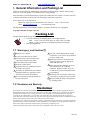
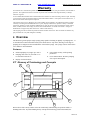
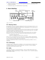
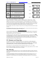
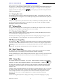
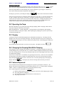
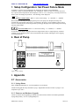
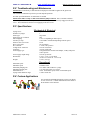
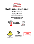
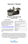
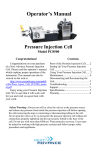
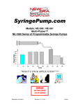
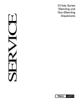
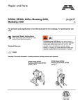
NEXT>>>ADVANCE www.nextadvance.com SP300 “Just Infusion” Programmable Syringe Pump Infusion Rate 60 50 40 30 20 10 0 0 10 20 30 40 50 60 70 80 90 Time WARNING NOT FOR CLINICAL USE ON HUMANS Doc: 1200-02 . Rev. 11 V3.7 03/23/10 www.nextadvance.com NEXT>>>ADVANCE SP300 Programmable Syringe Pump Quick Start Instructions Plug in the pump. Press the power switch to turn on power. Press any key to stop the display from blinking. Setup Pumping Parameters To Change Numbers: Use the arrow keys to increment individual digits. To move the decimal point: Press and hold the left-most arrow key for at least 1 second. When the digit increments from 9 to 0, the decimal point will begin to shift. Release the key when the decimal point is correct. Press any non-arrow key, or wait 2 seconds, to enter the new setting. The display will blink when a new value is entered and stored in memory. Set the Syringe Inside Diameter: Momentarily press the ‘Diameter’ key. Set the inside diameter of the syringe in millimeters (mm). Set the Pumping Rate. Momentarily press the ‘Rate’ key. To change the pumping rate units: Momentarily press the ‘Rate’ key again. The display will show: Press any arrow key to select the next available rate units. Press any non-arrow key, or wait 2 seconds, to set the rate units. Set the pumping rate. If the pumping rate is out of range, the display will show: Load the Syringe Press in the white drive-nut button to move the pusher block. Lift and turn the syringe clamp away from the syringe holder block Position the syringe on the pump with the flange to the left of the syringe holder block. Lift and turn the syringe clamp onto the syringe body. Move the pusher block next to the syringe plunger. Purge: Press and hold the ‘Start/Stop’ key for one second. Release to stop. Press and hold the direction button to reverse the pump and release the pusher block if jammed. Start the Pump: Press and release the ‘Start/Stop’ key to start or stop the pump. When Pumping The pumping rate can be changed. PUMP RESET: Press and hold the right-most up arrow key while turning on power to the pump. Need more pumping features? Visit www.nextadvance.com to see our full-featured syringe pumps. i 03/23/10 NEXT>>>ADVANCE www.nextadvance.com SP300 Programmable Syringe Pump Table of Contents 1. GENERAL INFORMATION AND PACKING LIST ................................................... 1 1.1 1.2 2. WARNINGS ! AND CAUTIONS ! .............................................................................. 1 DISCLAIMER AND WARRANTY ....................................................................................... 1 OVERVIEW ...................................................................................................................... 2 2.1 GLOSSARY OF TERMINOLOGY AND CONCEPTS ............................................................ 2 3. SETUP ................................................................................................................................ 3 4. LOADING SYRINGES..................................................................................................... 3 5. USER INTERFACE.......................................................................................................... 4 5.1 ENTERING VALUES ......................................................................................................... 4 5.2 LCD DISPLAY ................................................................................................................. 4 5.3 LEDS ............................................................................................................................... 4 5.4 ARROW AND DECIMAL POINT KEYS ............................................................................. 5 5.5 ‘DIAMETER’ AND ‘SETUP’ KEY...................................................................................... 5 5.6 ‘RATE’ KEY ..................................................................................................................... 5 5.6.1 PUMPING RATE UNITS .............................................................................................. 6 5.7 ‘VOLUME’ KEY ............................................................................................................... 6 5.7.1 CLEARING “VOLUME DISPENSED” ........................................................................... 6 5.8 REVERSE PURGE KEY .................................................................................................... 6 5.9 ‘START’/’STOP’ KEY ...................................................................................................... 6 5.10 ‘SETUP’ KEY ................................................................................................................ 6 5.11 SPECIAL POWER-UP FUNCTIONS ............................................................................... 7 5.11.1 FIRMWARE VERSION DISPLAY .................................................................................. 7 5.11.2 RESET PUMPING PARAMETERS ................................................................................. 7 5.12 ERROR AND STATUS MESSAGES ................................................................................ 7 6. OPERATION..................................................................................................................... 7 6.1 SYRINGE INSIDE DIAMETER........................................................................................... 7 6.1.1 VOLUME UNITS: DEFAULT AND HOW TO CHANGE.................................................. 7 6.2 OPERATING THE PUMP ................................................................................................... 8 6.3 PURGING.......................................................................................................................... 8 6.4 CHANGING THE PUMPING RATE WHILE PUMPING ...................................................... 8 6.5 VOLUME DISPENSED....................................................................................................... 8 7. SETUP CONFIGURATION: SET POWER FAILURE MODE .................................. 9 8. REAR OF PUMP............................................................................................................... 9 9. APPENDIX ........................................................................................................................ 9 9.1 ACCESSORIES .................................................................................................................. 9 9.1.1 SYRINGE HEATER ..................................................................................................... 9 9.1.2 FIRMWARE AND HARDWARE UPGRADE ................................................................... 9 9.2 TROUBLESHOOTING AND MAINTENANCE ................................................................... 10 9.3 SPECIFICATIONS ........................................................................................................... 10 9.4 CUSTOM APPLICATIONS............................................................................................... 10 9.5 SYRINGE DIAMETERS AND RATE LIMITS .................................................................... 11 ii 03/23/10 NEXT>>>ADVANCE www.nextadvance.com SP300 Programmable Syringe Pump 1. General Information and Packing List Thank you for purchasing the Model SP300 “Just Infusion”™ Syringe Pump. With the SP300 syringe pump you will be able digitally set an infusion rate for steady pumping. Please familiarize yourself with the SP300’s operation by reading this user's manual. For future reference, record the serial number, located on the rear of the pump, and the date of purchase. Next Advance Inc. can be contacted at: Phone USA: (800) 738-1681 International: (518) 674-3510 FAX: (518) 674-0189 Email: [email protected] www.nextadvance.com This Operating Manual, and the SP300’s hardware, electronics and firmware are copyrighted. Copyright 1999-2009, all rights reserved. Packing List Included with the SP300 Syringe Pump are the following items: One of the following external unregulated power supply adapters: Input: One of: 120V AC 60 Hz, 220V AC 50 Hz, 240V AC 50 HZ Output: 12V DC @ 800 mA (or compatible regulated power supply) This Operating Manual 1.1 Warnings ! ! ! ! ! ! ! ! ! and Cautions ! ! Read the user’s manual No user serviceable parts are inside. Disconnect power from the pump when connecting or disconnecting cables. Do not immerse the pump in liquid Install on a stable surface. Keep hands and loose clothing away from the pump's moving parts. The pump can automatically start when the Pumping Parameters is operating or when attached to an external control device. Prevent liquids from entering openings in the rear of the pump. ! ! ! ! Use only with the supplied power supply connected to a power source as specified on the power supply label. Do not push objects of any kind into the chassis openings, except for appropriate cables and connectors. If the pump becomes damaged, do not use unless certified safe by a qualified technician. Damage includes, but is not excluded to, frayed cords and deterioration in performance. Discharge static from control cables before connecting by touching the cable to ground. Before touching the pump, discharge static by touching ground. 1.2 Disclaimer and Warranty Disclaimer Next Advance Inc. makes no representations or warranties, expressed, statutory or implied, regarding the fitness or merchantability of this product for any particular purpose. Further, Next Advance Inc. is not liable for any damages, including but not limited to, lost profits, lost savings, or other incidental or consequential damages arising from ownership or use of this product, or for any delay in the performance of its obligations under the warranty due to causes beyond its control Next Advance Inc. also reserves the right to make any improvements or modifications to the product described in this manual at any time, without notice of these changes. Next Advance Inc. products are not designed, intended, or authorized for use in applications or as system components intended to support or sustain human life, as a clinical medical device for humans, or for any application in which the failure of the product could create a situation where personal injury or death may occur. All brand and product names used in this manual are the trademarks of their respective owners. 1 03/23/10 NEXT>>>ADVANCE www.nextadvance.com SP300 Programmable Syringe Pump Warranty Next Advance Inc. warranties this product and accessories for a period of two year, parts and labor, from the date of purchase. The repaired unit will be covered for the period of the remainder of the original warranty or 90 days, whichever is greater. A return authorization number must be obtained from Next Advance Inc. before returning a unit for repair. Warranty covered repairs will not be performed without a return authorization number. At the option of Next Advance Inc., a defective unit will be either repaired or replaced. This warranty does not cover damage by any cause including, but not limited to, any malfunction, defect or failure caused by or resulting from unauthorized service or parts, improper maintenance, operation contrary to furnished instructions, shipping or transit accidents, modifications or repair by the user, harsh environments, misuse, neglect, abuse, accident, incorrect line voltage, fire, flood, other natural disasters, or normal wear and tear. Changes or modifications not approved by Next Advance Inc. could void the warranty. The foregoing is in lieu of all other expressed warranties and Next Advance Inc. does not assume or authorize any party to assume for it any other obligation or liability. 2. Overview The SP300 is a general purpose single syringe pump capable of infusing at digitally set pumping rates. It is controlled from a microcontroller based system which drives a step motor, allowing a wide range of pumping rates configured to the inside diameter of the loaded syringe. The syringe is driven from a drivescrew and drive-nut mechanism. Features: Infusion pumping of syringes up to 140 cc. Pumping rates from 0.73 l/hr with a 1 cc to 1500 ml/hr with a 60 cc. Non-volatile memory of all operating parameters. Power Failure Mode: Re-starts pumping after a power interruption. Display of infused volume. 2.1 Glossary of Terminology and Concepts 3 4 5 6 7 2 1 8 10 9 When a device has as many features as the NE-1000 family, understanding its operation could be a daunting task at first. By understanding the key concepts and terminology used in this manual, the 2 03/23/10 www.nextadvance.com NEXT>>>ADVANCE SP300 Programmable Syringe Pump operation of the SP300 will become quite intuitive. Every effort has been made to design the SP300 with a consistent and intuitive user interface. To facilitate and enhance your understanding of the SP300’s operation, please take the time to familiarize yourself with the basic concepts below: Parts of the Pump 1) Pusher Block 5) Drive-Screw 8) Syringe Clamp 2) End Plate 6) Syringe Holder Block 9) Keypad / User Interface 3) Power On/Off Switch 7) ‘V’ Slot (on Syringe Holder Block) 10) Guide Rod (2 guide rods) 4) Drive-Nut Button Parts of a Syringe Plunger Flange Plunger Barrel Flange Barrel Terminology Momentary Press: A quick press, less then 1 second, then release of a key on the keypad. Display Blink: A momentary blanking of the LCD display. This indicates that the new data entered by the user is valid and has taken affect. 3. Setup Place the pump on a stable surface. Plug the round connector end of the supplied power supply adapter into the power plug located on the lower right of the pump's rear. See section 8, Rear of Pump, for a diagram of the rear of the pump. Plug the other end of the power supply adapter into an appropriate electrical outlet. The pump will be powered when the bottom of the power switch, located on the upper right of the rear of the pump, labeled ‘1’, is pressed. The red indicator on the switch is visible when the power switch is in the ‘on’ position. After power is applied to the pump, the pump’s display will flash. Next the Pumping Parameters can be entered. Before the pump can be started, the pump needs the measurement of the inside diameter, in millimeters, of the syringe that will be loaded. The syringe diameter can be entered using the keypad on the front panel of the pump. Finally, the syringe can be loaded and the pump started. 4. Loading Syringes The syringe is loaded by securing the barrel and the pusher flange as follows: 1: Press in fully the white drive-nut button on the pusher block, releasing the block. Taking care not to drag the drive-nut on the drive-screw, slide the block away from the syringe holder, providing sufficient space for the loaded syringe. Then release the white button. 2: Lift the syringe holder above the syringe holder block. Turn it 1/4 turn and then lower it onto the syringe holder block. The syringe holder should be out of the ‘V’ slot. 3: Load the syringe with the barrel over the syringe holder and the syringe plunger towards the middle of the pump. Place the barrel on the syringe holder, in the ‘V’ slot, with the barrel flange to the left of the syringe holder block. 4: Lift the syringe holder to slightly above the height of the syringe barrel and turn the syringe holder 1/4 turn back to its original position and then lower it onto the syringe barrel. 3 03/23/10 NEXT>>>ADVANCE 5: www.nextadvance.com SP300 Programmable Syringe Pump Then press the white drive-nut button and slide the pusher block against the syringe plunger. Release the white drive-nut button. To unload the syringe, reverse the instructions for syringe loading. 5. User Interface Volume Dispensed Units Reverse Purge Indicators Indicator Indicator mm ml l Rate Program Phase # Dispensed min Withdraw hr Motor Operating Pumping Volume Diameter Start Program Function Setup Stop Reverse Purge Key Unused Functions Figure 1: Front Panel 5.1 Entering Values When applicable, values can be changed by displaying the current value, then using the arrow keys. The new value will be stored in the pump’s non-volatile memory, meaning that the new value will not be lost the next time that power is applied to the pump. A displayed value can be changed by pressing the arrow keys below each digit. If the value to be changed is not currently displayed, when applicable, press the key associated with the required value. The display will show the setting’s current value and its units, if any. While the current value is being changed, the units LEDs associated with the value, if any, will blink. Except where noted, the new value is stored, and/or the selected operation takes affect, when either 1) A non-arrow key is pressed or 2) After a 2 second delay since the last arrow key was pressed. If the new value is valid and different from the original value, the display will blink, indicating that the new value was stored. Otherwise, if the value was invalid, an error message will be displayed. Pressing any key clears the error message and restores the original value. In general, if a parameter has 2 values, ‘off’ and ‘on’, they are represented by the numbers ‘0’ and ‘1’, respectfully. 5.2 LCD Display The display consists of a 4 digit reflective LCD display. This is the general purpose user display device for displaying floating point values, functions and parameters. The colon (:) is used for separating function abbreviations from their parameter values. 5.3 LEDs To the right of the LCD are 8 red, round, LED indicators. The first 2 columns display the units of the displayed values. Units are expressed using 1 or 2 LEDs. For instance, ‘ml / hr’ is expressed by lighting the ‘ml’ and the ‘hr’ LEDs. Publication #1200-01 4 03/23/10 NEXT>>>ADVANCE www.nextadvance.com LED Description mm Millimeters ml Milliliters min Minutes l Microliters hr Hours Withdraw Pumping Direction: Lit: Withdraw Purge Pumping Dispensed Displayed volume is dispensed volume Pumping Lit: Not lit: SP300 Programmable Syringe Pump Pumping rate units are expressed using 2 LEDs: ‘ml/min’ = ‘ml/hr’ = ‘l/min’ = Motor is operating The Pump is stopped ‘l/hr’ = ml min l hr ml min l hr ml min l hr ml min l hr 5.4 Arrow and Decimal Point Keys Each of the four digits in the display is associated with the up arrow key directly below it. When applicable, the arrow key is used to increment the value of that digit, or advance to the next setting. Each press of an up arrow key will increase the digit by 1, up to 9, and then back to 0. The arrow keys may also be held down for continuous incrementing of numbers. Some parameters have a fixed range of values, such as some setup parameters that are either turned on or off. In these cases, the arrow key will only scroll up to the maximum value for that parameter, then back to the minimum value. When changing a value’s units, each press of any arrow key will change the units LEDs to the next units selection. When the display blinks, the new value is stored and takes affect. This will occur when a non-arrow key is pressed or after a 2 second delay since the last key press. Decimal Point Key There are 4 decimal point positions on the LCD display. Each decimal point position is to the right of a digit in the display. The last decimal point position, to the right of the right-most digit is not displayed, indicating whole numbers with no decimal point. To change the position of the decimal point, use the left-most up arrow key / decimal point key (/). Press and hold this key for at least 1 second and wait until the left-most digit scrolls from ‘9’ to ‘0’. While continuing to hold this key, the decimal point will shift 1 position to the right. After the right-most decimal point position, the decimal point will shift to the first decimal point position. Release the key when the decimal point is in the required position. 5.5 ‘Diameter’ and ‘Setup’ Key The ‘Diameter’ key allows the syringe inside diameter to be viewed and set. While displaying the diameter, the ‘mm’ LED is lit. With the Pump stopped, momentarily pressing this key will display the current diameter setting. Pressing the arrow keys will change the current diameter (see sec. 5.4, Arrow and Decimal Point Key). The ‘mm’ LED will blink while the diameter is being changed. If the ‘Diameter’ key is pressed and held, ‘Setup’ mode will be entered. (see sec. 5.10, ‘Setup’ ). When the Pump is operating, pressing this key will display the current syringe diameter for review. When the key is released, the display returns to its previous display. 5.6 ‘Rate’ Key The ‘Rate’ key allows the pumping rate to be viewed or changed while pumping or stopped. While the pump is stopped, momentary presses of this key will switch between the ‘Rate’ display and the select rate units mode. To change the pumping rate displayed, while pumping or stopped, use the up arrow keys (see sec. 5.4, Arrow and Decimal Point Key). The rate units will blink while the rate is being changed. The new pumping rate is entered and takes affect immediately when the display blinks after a 2 second delay or Publication #1200-01 5 03/23/10 NEXT>>>ADVANCE www.nextadvance.com SP300 Programmable Syringe Pump when a non-arrow key is pressed. The new pumping rate is stored in memory. See section 9.5, “Syringe Diameters and Rate Limits”, for a list of minimum and maximum pumping rates. A pumping rate of 0.0 will stop the pump. When the pumping rate is changed, if it is out of range of the . Pressing any key clears the message and returns pumping rate limits, the display will show to the previous pumping rate. 5.6.1 Pumping Rate Units The pumping rate units can only be changed when the Pump is stopped. A momentary press of the ‘Rate’ key will enter Rate Units Change mode. The 2 LEDs representing the units will blink and the display will show: . Each press of any up arrow key selects the next rate units, as indicated by the blinking units LEDs. When the required rate units are blinking, press any non-arrow key or wait 2 seconds. The display will blink, indicating the rate units are stored in memory. 5.7 ‘Volume’ Key Pressing this key will display the “Volume Dispensed”, as indicted by the ‘Dispensed’ LED. The units of the volume are set according to the syringe diameter, but can be changed. 5.7.1 Clearing “Volume Dispensed” With the pump stopped and displaying the “Volume Dispensed”, pressing and holding any up arrow key for one second will reset the dispensed volume to 0. Immediately after entering a new syringe diameter and before starting the pump, pressing any up arrow key while displaying the “Volume Dispensed” will enter the “Set Volume Units” mode. 5.8 Reverse Purge Key The direction key, ‘ ’, is used to un-jam the pusher block after an over infusion, making it difficult to release the nut block. Press and hold this button for at least 1 second to reverse purge the pump until the pusher block is released. Release this key to stop the pump. While this key is held, the display will show: . The Withdraw and Pumping LED’s will be lit during the reverse purge. 5.9 ‘Start’/’Stop’ Key The ‘Start/Stop’ key starts or stops the Pump’s operation. Pressing this key switches between Pumping and the Pump stopped. The ‘Pumping’ LED will indicate that the Pump is pumping. Pressing and holding this key while starting the Pump will start the purge mode. Purge will begin after the key is held for one second, and continue until the key is released. The pump stops after the key is released. 5.10 ‘Setup’ Key The secondary function of the ‘Diameter’ key is ‘Setup’. While the Pump is stopped, press and hold the n ‘Diameter’ key until the setup configuration parameter, “Power Failure Mode”, is displayed: . The display will consecutively display, for about 2 seconds, each Setup Configuration parameter and its current setting. Pressing any non-arrow key will immediately advance to the next Setup Configuration parameter, if any. To change a Setup Configuration parameter, press an arrow key under the parameter’s value. To store the new value, press any non-arrow key or wait 2 seconds. If the parameter value differs from its previous value, the display will blink. The new parameter value will be stored and the next parameter will be displayed, if any. See section 7, Setup Configuration for a complete description of the Setup Configurations. After the last configuration parameter is displayed, the display reverts back to displaying the syringe Publication #1200-01 6 03/23/10 www.nextadvance.com NEXT>>>ADVANCE SP300 Programmable Syringe Pump diameter. Any new parameter value will take affect immediately upon being stored. 5.11 Special Power-Up Functions The following special functions are accessed by pressing the relevant key, while turning on power to the pump. 5.11.1 Firmware Version Display To display the pump’s firmware version, press the left-most up arrow key (/) while turning on , or similar. Pressing any key will clear the power to the pump. The display will show: display. 5.11.2 Reset Pumping Parameters To clear out the current Pump setups, press the right-most up arrow key () while turning on power to the pump. The display will show . Pressing any key will clear the display. With pumps having as many complex features as the NE-1000 family, it is easy for a novice user experimenting with the pump's setup to get the pump into a 'weird' state. Performing this reset function will bring the pump out of a 'weird' state. 5.12 Error and Status Messages Value entered is ‘Out Of Range’ of the pump’s operational limits. Check the pumping rate and/or the syringe inside diameter setting is correct. Key pressed is not currently applicable. Indicates pumping rate or volume units change mode. The units LED's will also be blinking. Press any up arrow key to change the units. Indicates that the pump is purging. Displayed while holding down the 'Start/Stop' key. Displayed while holding down the direction key and performing a reverse purge. 6. Operation Before the pump can be operated, the pumping data must be setup. The syringe inside diameter and a non-zero pumping rate needs to be set. The operation of the pump can then be started by pressing the ‘Start / Stop’ key. 6.1 Syringe Inside Diameter The syringe inside diameter can only be set while the Pump is stopped. Use the up arrow keys to set the diameter value. While the diameter value is being set, the ‘mm’ LED will blink. The new diameter value is stored after pressing any non-arrow key, or after a 2 second delay. Valid syringe diameters are from 0.1 mm to 50.0 mm. If the diameter is out of this range, the display will show ‘oor’. Pressing any key restores the diameter display to its previous value. Changing the syringe diameter will not zero the pumping rate. Section 9.5, “Syringe Diameters and Rate Limits”, is a representative list, for reference, of syringe diameters for various syringe manufacturers and syringe sizes. 6.1.1 Volume Units: Default and How to Change The units of the accumulated infusion volume is set according to the syringe diameter setting. If the default volume units are changed (see next section), the selected volume units will remain in affect until a reset function is performed. From 0.1 to 14.0 mm From 14.01 to 50.0 mm Publication #1200-01 Syringes smaller than 10 ml: Syringes greater than or equal to 10 ml: 7 Volume units are ‘l’ Volume units are ‘ml’ 03/23/10 NEXT>>>ADVANCE www.nextadvance.com SP300 Programmable Syringe Pump Changing Volume Units The volume units used for the accumulated volume can be changed to either ‘ml’ or ‘l’. NOTE: Volume units can only be changed immediately after setting the syringe diameter and before the pump is started. After the syringe diameter is entered, display the “Volume Dispensed” by pressing the “Volume” key. The current volume units and the “Dispensed” LED will be lit. and the current volume units will blink. Pressing any up arrow key will change the display to Then, press any up arrow key to switch the volume units between ‘ml’ and ‘l’. Press any non-arrow key or wait 2 seconds to enter the new volume units. The display will blink when entered. The selected volume units will remain in affect and override the default volume units. Changing the diameter will no longer change the volume units. Performming a system reset will cancel the override and allow the volume units to change to the default volume units when setting the syringe diameter. 6.2 Operating the Pump When the “Start/Stop” key is pressed, the Pump will begin pumping, and the ‘Pumping’ LED will be lit. The pump will pump continuously until stopped. Either the pumping rate, “Volume Dispensed”, or syringe diameter can be displayed while pumping. Press the relevant key to change the display. While displaying the pumping rate, press the up arrow keys to change the pumping rate. 6.3 Purging To purge the syringe, with the Pump stopped, press and hold the 'Start/Stop' key. The Pump will start pumping, then, after one second, purge will begin. The pump will pump at its top speed. Purging will continue until the 'Start/Stop' key is released, and then the pump will stop. While purging the display will show: . Press and hold the direction button, to perfrom a reverse purge. The display will show: 6.4 Changing the Pumping Rate While Pumping The pumping rate can be changed while the pump is operating. To change the pumping rate, display the current pumping rate by pressing the ‘Rate’ key, if needed. With the pumping rate displayed, press the up arrow keys to change the rate. The rate units will blink while the rate is being changed. Rate units can not be changed while pumping. The new rate is stored after a 2 second delay or by pressing a non-arrow key. If the new rate is within the operating range of the pump, the display will blink and the new rate will be stored in memory and the pump will begin pumping at the new rate. If the new rate is out of the operating range of the pump, the display will show . Pressing any key clears the message and restores the previous rate. 6.5 Volume Dispensed The accumulated Volume Dispensed can be displayed at any time by pressing the Volume key. The display will show the total accumulated volume pumped with the ‘ml’ or ‘l’ LED lit and the ‘Dispensed’ LED lit. Volume is computed based upon the syringe inside diameter setting. The “Volume Dispensed” accumulation is reset to 0 when: A) B) C) D) With the pump stopped, pressing and holding any up arrow key while displaying the volume. The syringe diameter is changed. The accumulated Volume Dispensed rolls over from 9999 to 0. The pump is powered on. Publication #1200-01 8 03/23/10 NEXT>>>ADVANCE www.nextadvance.com SP300 Programmable Syringe Pump 7. Setup Configuration: Set Power Failure Mode To change or view the setup configuration, the Pump must be stopped. Press and hold the ‘Diameter’/‘Setup’ key until the parameter, ‘PF’ is displayed. After 2 seconds, or when any non-arrow key is pressed, the next parameter will be displayed . (See sec. 5.10, ‘Setup’ Key). Pressing an arrow key under a value will change the parameter. The following will be displayed: n Power Failure Mode. Where ‘n’ is the current setting.: ‘0’ = Disabled, ‘1’ = Enabled. When enabled, if the Pump was pumping when power to the pump was disrupted, the Pump will automatically start pumping when power is reconnected to the pump. The accumulated volume will be reset to 0. Pressing any key on the keypad while powering up the pump will stop the Pump from starting in Power Failure Mode. n Low Noise Mode, Where ‘n’ is the current setting.: ‘0’ = Disabled, ‘1’ = Enabled. A side affect of the SP300’s high precision micro-stepped motor driver is a high frequency resonance sound at very low pumping speeds. This mode minimizes this sound by reducing the micro-stepping, increasing pulsations. 8. Rear of Pump NEW ERA PUMP SYSTEMS, Inc. WWW.SYRINGEPUMP.COM (631) 249-1392 Farmingdale, NY [email protected] NE-300 Figure 2: Rear of Pump 9. Appendix 9.1 Accessories 9.1.1 Syringe Heater Part#: SYRINGE-HEATER, see www.SyringeHeater.com for details. Flexible heating pad that wraps around the syringe. Digital PID controller will heat a syringe to a set temperature up to 100 C. 9.1.2 Firmware and Hardware Upgrade Contact your dealer about upgrading your pump with other features from the NE-1000 Programmable Syringe Pump family. See www.SyringePump.com Publication #1200-01 9 03/23/10 NEXT>>>ADVANCE www.nextadvance.com SP300 Programmable Syringe Pump 9.2 Troubleshooting and Maintenance Maintenance: Periodically, a small amount of all-purpose oil should be applied to the guide rods. The mechanism should be kept clean to prevent impeded operation. No other special maintenance or calibrations are needed Pusher block makes a snap or click sound when the pump is started: This is a normal condition. When the pusher block is manually moved, the drive-nut may not have been fully engaged on the drive screw. The sound heard is the drive-nut engaging on the drive screw. 9.3 Specifications Mechanical & Electrical Syringe sizes: Number of syringes: Motor type: Motor steps per revolution: Microstepping: Advance per step: Motor to drive screw ratio: Drive screw pitch: DC connector: Voltage at DC connector: Amperage: Power supply type: Power supply output rating: Dimensions: Weight: Up to 140 cc 1 Step motor 400 1/8 to 1/2 depending on motor speed 0.2126 uM to 0.8504 uM depending on motor speed 15/28 20 revolutions/” 2.1 mm, center positive 12V DC at full load 750 mA at full load Unregulated linear external wall adapter, country and power source specific 12V DC @ 800 mA 8 3/4” x 5 3/4” x 4 1/2” High (22.86 cm x 14.605 cm x 11.43 cm) 3.6 lbs. (1.63 kg) Operational Maximum speed: Minimum speed: Maximum pumping rate: Minimum pumping rate: Maximum force: Syringe inside diameter range: 3.7742 cm/min 0.004205 cm/hr 1257 ml/hr with a B-D 60 cc syringe 0.73 l/hr with a B-D 1 cc syringe 35 lbs. at minimum speed, 18 lbs. at maximum speed 0.100 to 50.00 mm 9.4 Custom Applications For specialized and OEM applications, contact your dealer or Next Advance Inc. Custom modifications can be made to the mechanics or the firmware. Publication #1200-01 10 03/23/10 NEXT>>>ADVANCE www.nextadvance.com SP300 Programmable Syringe Pump 9.5 Syringe Diameters and Rate Limits Next Advance www.nextadvance.com Model: SP300 syringe pump Maximum and minimum flow rates Syringe (cc) Inside Diameter (mm) Maximum Rate (mL/hr) Minimum Rate (µl/hr) Maximum Rate (mL/min) B-D 1 3 5 10 20 30 60 4.699 8.585 11.99 14.43 19.05 21.59 26.59 39.27 131 255.6 370.3 645.4 829 1257 0.73 2.434 4.748 6.876 11.99 15.4 23.35 0.6545 2.184 4.261 6.172 10.75 13.81 20.95 HSW Norm-Ject 1 3 5 10 20 30 50 4.69 9.65 12.45 15.9 20.05 22.9 29.2 39.11 165.6 275.6 449.6 714.9 932.6 1516 0.727 3.076 5.119 8.349 13.28 17.32 28.16 0.6519 2.76 4.594 7.493 11.91 15.54 25.27 1 3 6 12 20 35 60 140 5.74 8.941 12.7 15.72 20.12 23.52 26.64 38.00 58.59 142.1 286.8 439.4 719.9 983.8 1262 1.088 2.64 5.326 8.161 13.37 18.27 23.44 47.69 0.9766 2.369 4.78 7.324 11.99 16.39 21.03 42.80 Terumo 1 3 5 10 20 30 60 4.7 8.95 13 15.8 20.15 23.1 29.2 39.28 142.4 300.5 443.9 722.1 949 1516 0.73 2.646 5.581 8.244 13.41 17.63 28.16 0.6547 2.374 5.009 7.399 12.03 15.81 25.27 Air-Tite 10 20 30 50 15.9 20.25 22.5 29 449.6 729.2 900.3 1495 8.349 13.55 16.72 27.78 7.493 12.15 15 24.92 Syringe (µL) Inside Diameter (mm) Maximum Rate (µl/hr) Minimum Rate (µl/hr) Hamilton Microliter 0.5 1 2 5 0.103 0.146 0.206 0.326 18.86 37.91 75.47 189 0.001 0.001 0.002 0.004 SGE 0.5 1 0.1 0.15 17.78 40.01 0.001 0.001 Syringe Manufacturer Monoject Publication #1200-01 11 03/23/10