Download User Manual UT
Transcript
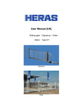
User Manual Sliding gate drives UT DELTA ODYSSEUS English Version: 1.1 September 2013 Translation of the Original User Manual English 2 CONTENTS 1 GENERAL ...................................................................................................... 4 1.1 1.2 1.3 1.4 1.5 1.6 1.7 2 MANUFACTURER / SUPPLIER ...................................................................... 4 SERVICE / MAINTENANCE .......................................................................... 4 TYPE ...................................................................................................... 4 HOW TO USE THIS MANUAL ....................................................................... 4 DEFINITIONS: USER / OPERATOR / ENGINEER .............................................. 5 EXPLANATION OF THE SYMBOLS ................................................................. 5 CONFORMITY WITH EUROPEAN DIRECTIVES................................................. 5 SAFETY ......................................................................................................... 5 2.1 2.2 3 GENERAL SAFETY INSTRUCTIONS ............................................................... 5 SAFETY DURING INSTALLATION, DISASSEMBLY, USE AND MAINTENANCE ........ 6 INSTALLATION DRIVE .................................................................................. 7 3.1 3.2 3.3 MOUNTING THE RACK ............................................................................... 7 INSTALLING THE MOTOR UNIT ................................................................... 8 ADJUSTING THE MOTOR UNIT .................................................................... 8 4 INSTALLATION ............................................................................................. 9 5 COMMISSIONING ......................................................................................... 9 5.1 6 INTENDED USE ........................................................................................ 9 MANUAL OPERATION IN THE EVENT OF FAULTS ......................................... 10 6.1 DISENGAGING THE MOTOR ...................................................................... 10 7 EMERGENCY STOP ...................................................................................... 10 8 MAINTENANCE INSTRUCTIONS .................................................................. 10 8.1 8.2 8.3 9 GATE MAINTENANCE ............................................................................... 10 PERSONAL SAFETY AND REGULAR INSPECTION........................................... 10 CLEANING ............................................................................................. 11 DECOMMISSIONING AND REMOVAL ........................................................... 11 10 TECHNICAL DATA .................................................................................... 12 10.1 10.2 SLIDING GATE DESCRIPTION ................................................................ 12 TECHNICAL DETAILS............................................................................ 12 APPENDIX A: INSTALLATION OF PERSONAL PROTECTION DEVICE................... 13 APPENDIX B: WIRING DIAGRAM ISK UNIT ....................................................... 14 APPENDIX C: DECLARATION OF CONFORMITY .............................................. 15 English 3 1 GENERAL 1.1 MANUFACTURER / SUPPLIER Manufacturer: Heras B.V. Hekdam 1, 5688 JE Oirschot Netherlands Tel.: +31(0)499-551225 www.heras.com Technical Construction File Heras B.V. manager, R&D Department 1.2 SERVICE / MAINTENANCE In the event of problems, failures or questions you can contact: Heras Service Tel. 0900 202 0499* Fax 0900 202 4550 * local rate Only available from the Netherlands. If you are located elsewhere, please contact your dealer for assistance. 1.3 TYPE The UT is intended for the following types of Heras sliding gate: Delta Odysseus The UT is available in 2 versions: Cardin SL100/1524 [for active anti-crushing safety protection device] Cardin SL100/1524HER [for passive anti-crushing safety protection device] 1.4 HOW TO USE THIS MANUAL Carefully read this User Manual before using the sliding gate and save it for future reference. This description was made for the people who operate the gate. Fitters use a separate installation manual. There is also a separate installation diagram for fitters to install the drive in question in compliance with the applicable norms and standards. If any faults occur, consult a Heras-certified engineer. This manual is an addition to the manuals enclosed with the HMD230/IGD drive and control units. English 4 1.5 DEFINITIONS: USER / OPERATOR / ENGINEER User: Anyone using the gate. Operator: A user who is familiar with all safety aspects dealt with in this manual. Operators are not allowed to carry out any installation work on the gate unless explicitly specified. Engineer: The engineer is a Heras fitter (or an engineer employed by the customer who has been given explicit permission in writing from Heras) who is qualified to perform technical interventions on the gate. 1.6 EXPLANATION OF THE SYMBOLS 1.7 Caution!: To prevent personal injury, you must observe the safety instructions below. Note!: To prevent material damage, you must observe the safety instructions below. Information: This is followed by further information or by a reference to other documents. Warning: Risk of limbs getting crushed Warning: Risk of injury to hands by gear wheels CONFORMITY WITH EUROPEAN DIRECTIVES The installation complies with the following EU Directives: 2006/42/ EC Machine Directive 2004/108 EC EMC Directive (electromagnetic compatibility) The EC Declaration of Conformity can be found in appendix C. The CE mark is located on the rear of the bottom rail of the gate 2 SAFETY 2.1 GENERAL SAFETY INSTRUCTIONS The operator must read the entire user manual before the gate is used for the first time. The instructions stated in the user manual must be observed and complied with. All other forms of use can cause unexpected hazards and are forbidden. It is forbidden to apply the drive unit to gates other than those stated in this manual, English 5 2.2 without Heras' permission. Applying a third-party drive unit and/or anti-crushing safety protection device may affect safety and will invalidate the CE mark. The gate must only be put into use if all safety facilities are in place and connected, and work properly. All faults which might present a source of danger to the user or to third persons must be eliminated immediately. All warnings and safety notices on the equipment must be in place and clearly legible at all times. The gate must be able to move freely without there being obstacles in the gate opening passage or anywhere else on the moving trajectory of the gate. Do not stick any objects through, over or under the gate which might block the gate. The gate running surface must always be free from snow, ice or dirt that might affect its sliding behavior. In the event of frost, check this before commissioning the gate. If the running surface is blocked, the gate will not move at all or will not complete its movement. An irregular running surface may cause damage to the drive and/or road wheels. Climbing the gate is strictly forbidden as people climbing the gate could be hurt if the gate is started unexpectedly. Closing the gate infill openings in any way, such as by means of banners, advertising signs etc, is not allowed as this may negatively affect the safe operation of the gate. All alterations or extensions to the gate must be carried out by qualified personnel using parts which the manufacturer has defined as suitable for such alterations or extensions. Any failure to comply with these instructions will be considered as non-compliant behavior and will invalidate the manufacturer's guarantee, as a result of which the risk entirely transfers to the user. Improper usage or servicing or ignoring the operating instructions can be a source of danger for persons, and/or result in material damage. If the meaning of any part of these installation and operating instructions is not clear, then please contact your supplier before you use the equipment. SAFETY DURING INSTALLATION, DISASSEMBLY, USE AND MAINTENANCE English When work is carried out on the gate, the power supply to the system must be switched off and it must be ensured that it cannot be switched on unexpectedly. Interrupt the power supply while cleaning the gate. Use the necessary personal safety equipment. Keep a safe distance from the moving gate. Warning icons to this effect have been installed in various locations. The gate has safety facilities such as anti-crushing safety protection devices. The anti-crushing safety protection devices serve as emergency facilities to immediately stop and reverse the gate movement. Using them as a regular gate stop feature is not allowed. Since the head stiles of the gate have anti-crushing safety protection devices that cannot cover their full height, there is still some risk of people getting trapped by the gate here. The gate is driven by means of a gear wheel. This is located under the beam and it is partly screened off by the drive unit cabinet. Beware of moving parts when carrying out maintenance under the gate at the drive unit cabinet. To move the gate manually, first switch the automatic fuse in the drive unit cabinet to “off” and make sure it cannot be switched on again (e.g. by locking the cabinet). Always lock the drive unit cabinet during use. The drive unit cabinet may only be opened by an electrical engineer. The EN 13241-1, EN 12453 and EN 12445 standards must be taken into consideration during installation. To achieve a good safety level, both the above standards and the national regulations must be taken into account in non-EC countries. 6 The Delta, uGate and iGate have highly tensioned cables fitted in the bottom rail. If these cables are damaged, they can snap with great force. This can lead to serious injury. Therefore, it is prohibited to drill into or grind these rails. !! Only people trained by Heras are allowed to disassemble the bottom rail. If the gate is damaged, always contact the supplier for an inspection. 3 INSTALLATION DRIVE End stoppers (slam support front and rear) must be used at the ”open“ and “closed“ positions. The stopper for the closed position will also prevent the existing safety contact profiles from being actuated. 3.1 MOUNTING THE RACK The plastic rack is delivered as loose elements in lengths of approx. 500 mm. Connect these elements and insert them into the aluminium profile. Bij de begrenzing ’poort dicht’ moet voorkomen worden dat deze een eventueel aanwezig contactprofiel (persoonsbeveiliging) activeert. Delta English Odysseus 7 3.2 INSTALLING THE MOTOR UNIT The motor unit is fixed to the support provided. This support is attached to the post by means of clamping brackets. motor support principle 3.3 ADJUSTING THE MOTOR UNIT Position the toothrack holder in such a way that it can be slid upwards/downwards (Odysseus). Position the gate leaf in a central position. Adjust the height of the motor unit so that the toothed wheel falls into place in the toothrack. Caution: The toothrack must allow approx. 1mm movement tolerance for the toothed wheel! The motor must be connected. Check that the motor unit runs parallel with the gate leaf and is level. Tighten the nuts on the motor support. Check that the toothed wheel runs along the centre of the toothrack. Slide the gate open and closed all the way and check that the tolerance distance is approx. 1mm in all places. If necessary, adjust the height of the motor unit/toothrack holder. Check again that the toothrack has been installed correctly and that all screws, the toothrack holder and the motor unit have been tightened. Caution: English The emergency release operation must work in all gate positions. 8 4 INSTALLATION The sliding gate and the gate drive and control unit must be installed, connected, set up and tuned by a fitter or an engineer who also connects and programs any accessories. Active safety edges must be connected to the ISK unit. See Appendix B for wiring diagram. ISK unit The gate control unit is adjusted to the options/accessories agreed with the user. The relevant options are laid down during hand-over. Of course, you can add optional/accessories afterwards. Contact your supplier for this. Gates are always delivered fully tested. 5 COMMISSIONING 5.1 INTENDED USE The gate is intended to control access to a specific plot, premises or site. The gate is intended for both industrial and private use. The gate drive and control unit is adjusted to the options agreed with the user. The relevant options are laid down during hand-over. Carefully read this user manual before operating the gate. You must always be familiar with the operating mode the gate is in. See manual with Cardin SL100/1524 English 9 6 MANUAL OPERATION IN THE EVENT OF FAULTS 6.1 DISENGAGING THE MOTOR The gate can be opened by hand in emergency situations. The gear wheel of the drive unit will have to be disengaged from the toothed bar for this. See manual with Cardin SL100/1524 7 EMERGENCY STOP The UT does not have an emergency stop system. According to the Machine Directive 2006/42/EC, annex 1, article 1.2.4.3., this is not necessary if the emergency stop system would not lower the risk. However, an emergency stop system can be connected to the HMD230. 8 MAINTENANCE INSTRUCTIONS 8.1 GATE MAINTENANCE To ensure the optimum operation of the gate, Heras recommends having maintenance performed by a qualified engineer at least once a year or after every 7000 cycles. See the chapter “SERVICE /MAINTENANCE” 8.2 PERSONAL SAFETY AND REGULAR INSPECTION Depending on the configuration of the gate and the adjacent fencing, safety strips will be affixed at various points where there is a risk of entrapment. (See appendix APPENDIX A: INSTALLATION OF PERSONAL PROTECTION DEVICE). The gate is available with passive or active safety edges. By passive safety edges the gate will stop at a certain force. These forces must comply with EN 12453 and EN 12445. When exceeding the forces the CE marking expires. With active safety edges the gate stops immediately after pressing these edges. The safety strips must be regularly inspected visually (once a month) to check that they are undamaged and work properly. Switch off the gate if these safety facilities do not work properly, since optimum safety cannot be guaranteed. Contact Fout! Verwijzingsbron niet gevonden. English 10 8.3 CLEANING The gate and the outside of the drive unit cabinet can be cleaned using a non-aggressive detergent and a soft cloth, brush or sponge. Avoid using a pressure cleaner as this might damage the gate and the drive unit cabinet. Lubricating the running surface of the gate is not allowed. 9 DECOMMISSIONING AND REMOVAL At the end of their service lives the products must be disposed of in accordance with all local, regional and national rules and instructions. The sliding part is mainly made of aluminum parts. The guideposts are made of steel. Heras is also happy to take the products back and then dispose of them in an appropriate manner. The Delta, uGate and iGate gates have highly tensioned cables fitted in the bottom rail. If these cables are cut, they can snap with great force. This can lead to serious injury. Therefore, it is prohibited to disassemble the bottom rail yourself. !! Only people trained by Heras are allowed to disassemble the bottom rail. There is no hidden danger associated with dismantling the bars, top rail and stiles. The points that are fitted to some sliding gates are sharp. There is a danger of being cut when disassembling such a gate. Wear suitable gloves. Disposing of batteries as domestic waste is not allowed. Spent batteries can be handed in for free at the public municipal collection facilities and at all points of sale where batteries are sold. You can also return any batteries bought from us to us after use. In this way you will be making an important contribution to conserving the environment! English 11 10 TECHNICAL DATA 10.1 SLIDING GATE DESCRIPTION The gate was designed to enable an area to be automatically sealed off and made accessible again. This User Manual deals with the powered (cantilever) sliding gates listed below. Gate leaf Odysseus Delta Length [m] [5.05-11.55] [5.15-12.5] Height [m] [1.0-2.5] [1.0-2.5] Max. weight [kg] 725 120 Runner wheels Steel PA6G210 cantilever cantilever 10.2 TECHNICAL DETAILS See manual with Cardin SL100/1524 English 12 APPENDIX A: INSTALLATION OF PERSONAL PROTECTION DEVICE Below are the guidelines for the installation of the personal protection devices on Odysseus and Delta sliding gates. The diagram shows the sliding gate when viewed from above. Explanation of symbols: Personal protection strip Motor unit Line of Odysseus gate with gateposts (5x passive or active) Outside open Delta gate with gateposts (9x passive or active) Outside open English 13 APPENDIX B: WIRING DIAGRAM ISK UNIT English 14 APPENDIX C: DECLARATION OF CONFORMITY English 15


![User Manual [UK]](http://vs1.manualzilla.com/store/data/005991569_1-3b3b29e023250702c09408f0279394a4-150x150.png)


![User Manual [UK]](http://vs1.manualzilla.com/store/data/005698634_1-91739311a55a3b64211d9cd4e7c53c37-150x150.png)
