1
André Häggman
Bachelor´s thesis
Building Engineering
Vaasa 2012
BACHELOR’S THESIS
Author: André Häggman
Degree Programme: Building Engineering, Vaasa
Specialization: Structural Design
Supervisor: Kennet Kurman
Title: Application for calculating materials included in wall panel details in Tekla
Structures
_________________________________________________________________________
2.5.2012
16 pages
2 appendices
_________________________________________________________________________
Summary
In my Bachelor´s thesis for Citec, I have developed an application for Tekla Structures that
calculates the amount of materials used in the installation of light-weight sandwich wall
panels. Tekla Structures is a 3D-based modeling program that includes material data in its
model, which makes it superb for making both drawings and material lists. Tekla
Structures is mostly used in designing steel and concrete structures.
The application consists of custom components, a report template and a macro that makes
the final calculation and writes the result in a report. The result of this application is an
accurate and time-saving calculation of the materials.
_________________________________________________________________________
Language: English
Key words: Tekla Structures, custom component, template report, wall panels
_________________________________________________________________________
EXAMENSARBETE
Författare: André Häggman
Utbildningsprogram och ort: Byggnadsteknik, Vasa
Inriktningsalternativ: Byggnadskonstruktion
Handledare: Kennet Kurman
Titel: Applikation som räknar ut material inkluderade i väggpanel detaljer i Tekla
Structures
_________________________________________________________________________
2.5.2012
16 sidor
2 bilagor
_________________________________________________________________________
Sammanfattning
I detta examensarbete har jag på begäran av Citec utarbetat en applikation för
Structures som räknar ut materialåtgången för montering av lätta sandwichpaneler.
Structures är ett 3D-modelleringsprogram som inkluderar materialdata i modellen,
gör att programmet är ypperligt för att få fram både ritningar och materiallistor.
Structures används främst för planering av stål- och betongkonstruktioner.
Tekla
Tekla
vilket
Tekla
Applikationen är uppbyggd av custom componenter, en report template samt ett makro
som gör den slutliga beräkningen och sedan kör ut resultatet till en rapport. Applikationen
utför en noggrann beräkning av materialmängder samtidigt som tidsåtgången förminskas
väsentligt jämfört med manuella beräkningar.
_________________________________________________________________________
Språk: engelska
Nyckelord: Tekla Structures, custom component, template rapport, väggpaneler
_________________________________________________________________________
OPINNÄYTETYÖ
Tekijä: André Häggman
Koulutusohjelma ja paikkakunta: Rakennustekniikka, Vaasa
Suuntautumisvaihtoehto: Rakennesuunnittelu
Ohjaaja: Kennet Kurman
Nimike: Applikaatio joka laskee materiaaleja seinäpaneelien detaljien liittyen Tekla
Structuresissa
_________________________________________________________________________
2.5.2012
16 sivua
2 liitettä
_________________________________________________________________________
Tiivistelmä
_________________________________________________________________________
Kieli: englanti
Avainsanat: Tekla Structures, custom component, template raportti, seinäpaneeli
_________________________________________________________________________
Contents
List of appendices
Foreword
1
2
3
Introduction ................................................................................................................... 1
1.1
Citec ........................................................................................................................ 1
1.2
Tekla ....................................................................................................................... 1
Background of the project ............................................................................................. 2
2.1
Planning of the application ..................................................................................... 2
2.2
Custom components ................................................................................................ 3
Implementation .............................................................................................................. 4
3.1
Creating the Custom Component ............................................................................ 4
3.1.1
Modifying custom component settings ........................................................... 6
3.1.2
Editing of input file ....................................................................................... 10
3.2
Loading of detail materials ................................................................................... 11
3.3
Template editor ..................................................................................................... 12
3.3.1
Making of the template report ....................................................................... 13
4
Reflections and developments ..................................................................................... 15
5
Sources ........................................................................................................................ 16
Appendices
List of appendices
Appendix 1
Input file for detail EW_-1
Appendix 2
Detail Modelling with Custom Components, User manual
Foreword
Work efficiency is today highly emphasized. Developing working methods and software to
maximize profit and minimize time consumption and costs has become increasingly
important for companies in order to stay competitive on the customer market. Especially
when thinking about cheap foreign manpower, it is highly important to constantly keep on
doing development work for the purpose of producing services of high quality at a low
price. My thesis has been all about automatizing the work for the envelope design team at
Citec, by making an application that removes all manual calculations of materials included
in the wall panel design.
I have not done any kind of software programming before, so this has been something
totally new and exciting to me. At the beginning it felt like quite a big task to dig into, but I
have got invaluable help from coworkers and also from Tekla Helpdesk. The result
complies with what the customer wanted and the envelope team has been very pleased with
the application.
At last I want to thank all the people who have helped me through the practical part of my
Bachelor´s thesis and made it possible for me to make the application good and easy-touse. I want to send special thanks to Kennet Kurman (envelope team Design Manager),
Markus Vikström (Senior Application Specialist) and Peter Johansson (Project Manager) at
Citec and also to the employees at Tekla Helpdesk. I have been in contact with these
people throughout my thesis regarding challenges that I have not been able to meet by
myself.
André Häggman
1 Introduction
1.1 Citec
Citec is a global company founded in 1984 with its headquarter in Vaasa. They provide
multi-disciplined engineering and information management services for industry, and they
specialize in the energy and power section. Citec is also well up in many other areas, for
example rail vehicles, marine and process industries. The company has offices in Finland,
Sweden, the UK, France, Germany, Russia and India. (Citec 2009).
Due to the fact that Citec has designed over 1000 power plants around the world since
1984, energy and power industry is truly Citec´s expert area. The company has
approximately 1100 employees and had a turnover of about 60 million euros in 2011.
(Citec 2009).
From the former companies Citec Engineering Oy Ab and Citec Information Oy Ab, the
company was merged into one Citec Group in 2011. At this time, the fund management
Sentica Partners stepped into the company as a new majority shareholder with 67 percent
of the shares. (Citec 2009).
1.2 Tekla
Tekla Corporation was established in Finland in 1966 and has its headquarters in Espoo,
Finland. The company also has offices in Sweden, Denmark, Germany and U.S.A among
others. Tekla had a net sale of nearly 58 million euros in 2010 and an operating result of 10
million euros. The company employs more than 500 people and has customers in
approximately 100 countries. (Tekla 2012).
Tekla describe themselves on their homepage like this: ”Tekla develops model-based
software products for the architectural, engineering, and construction (AEC) market, for
local government use and for power companies.” Tekla Structures is one of the software
developed by Tekla. This software is a Building Information Modeling (BIM) software,
which makes it possible to exchange and visualize building information between all
building disciplines through the same 3D model. Tekla Structures includes material data in
its model, which makes it possible to get information about material weights, lengths and
areas from the model. Tekla Structures is developed for designing steel and concrete
structures. (Tekla 2012).
2 Background of the project
As I was working as a summer trainee at Citec in summer 2011, I also discussed with my
superiors about the possibility of doing my thesis work for Citec. After a few discussions it
became clear that my thesis wo k should be about program development. One requirement
was to develop and facilitate the calculation of detail materials.
Calculation of materials used in the assemblage of wall panels has been a time-consuming
part of the designing of Wärtsilä power plants. Detail materials have been calculated with
an Excel template and a lot of manual work has been included. All details and their total
lengths had to be inserted in the Excel template. The template had pre-defined materials for
standard details and it calculated the materials from the given details. Still, all flashings
had to be checked from the detail drawings and added to the calculation, since these were
not predefined.
It became my task to develop an application for Tekla Structures that calculates all the
materials automatically and then gives an output to an Excel list. I dicussed with my
supervisor Kennet Kurman and we came to the conclusion that the best solution is to create
custom components representing wall panel details.
At the kick-off meeting it was decided that my thesis should include the creation of
predefined custom components for all standard details used in Wärtsilä projects. My thesis
should also include a template report that calculates the amounts and then gives an output
in the form of a material list which can be opened in Excel. The application had to be both
quick and easy to use, and of course it had to make correct calculations.
2.1 Planning of the application
To make the application easy to use I decided to create different custom components for
each wall panel type. There are four different wall thicknesses for external walls and one
thickness for internal wall panels, and each of these has its own details. After I had created
the custom components and customized them for wall panel detail materials, I saved all
details including their materials so that the details could be found in a drop-down list. With
this solution I attained an organized system where you first choose the custom component
according to which wall panels that are used, and then you choose the detail from a dropdown list in the custom component dialog box.
To be able to calculate the amounts for different details I had to add a part to the
component that symbolized the actual detail. This made it possible to define the length of
the detail and in that way calculate the quantity of material needed on the basis of the total
length.
It was decided that I should create a template report to calculate the materials for every
detail separately and then write the amounts in a list. This is done by Tekla´s built-in
application, Template Editor. Since the template report cannot separate between different
attributes in order to sum up equal materials, a macro had to be produced. The macro´s
purpose is to read the report in order to select the wanted values from the report. The
macro then sums up the amounts and writes them to a list which can be opened in Excel.
This list is used for copying all the wanted information and then the information is pasted
to the real material list template. The macro included in this application was created by
Markus Vikström since I am not very familiar with programming. This would have been
too big a task for me to include in my thesis work.
2.2 Custom components
For defining parts, connections, seams and details, Tekla Structures contains a set of tools
called custom components. System components are also included in Tekla Structures by
default and often used for different kinds of connections between parts. Components can
for example include fastening plates, cuts, welds and bolts for connecting two beams
together. Custom components can be used in the same way as system components but they
are customized by the user.
On the basis of the needs, the user chooses which type of custom component is going to be
created. The custom component type decides how the custom component is going to work
and handle the parts selected as included parts. The different types of custom components
that can be created are: connection, detail, part and seam. (Tekla Corporation 2012, pp.715).
When a custom component is created, an input file with the same name as the custom
component is inserted in the model folder under CustomComponentDialogFiles. This file
defines the appearance of the custom component´s dialog box. By opening this text file in
for example Notepad, the file can be easily edited and tabs, fields, drop-down lists and
even pictures can be added to the dialog box by using C programming language. (Tekla
Corporation 2012, pp.49-55).
3 Implementation
To give a clear picture of what I have achieved in my thesis, I am in this chapter going to
go through every stage of making the application. This will also be a kind of user manual
for making a similar application. I have divided this chapter into several subchapters to
make it as clear as possible.
3.1 Creating the Custom Component
To be able to define multiple materials in one part, I had to make a custom component. To
make it easy to define details and their materials, all materials were written as a simple
text. This means that no parts were inserted from the object or the part catalog.
First I had to create a part that represented the actual detail. I made it as a beam to be able
to model it both vertically, horisontally and diagonally. In this case I used a PL50*50 that
was placed in the middle of the panel joint (see picture 1.). In this way it will not disturb
the appearance of the wall panels in general arrangement drawings. The beam properties
are not significant since the only actual function of the beam is to define the length of the
detail. Also, the name of the beam will function as a detail mark in general arrangement
drawings. This is described in chapter 3.1.1.
Picture 1. Making of custom component part.
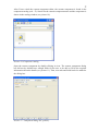
After I had created the part it was time to add it to a custom component. Custom
components are created with the Custom Component Wizard (see picture 2). To open the
wizard, go to Detailing in the main toolbar and select Component and Define Custom
Component.
Picture 2. Custom component wizard.
1/5
Choose from the drop-down list what type of custom component you want to
create, then fill in the name of the component. In this case, Seam is chosen and the
name EW_-1 is given to details for 100 mm wall panels.
2/5
Select the objects that will form the custom component. The two lowest wall panels
and the steel profile are chosen as objects of the custom component.
3/5
Select one of the wall panels as the main part of the custom component.
4/5
Pick the other wall panel as the secondary part.
5/5
The start and end points of the steel profile are chosen as insertion points of the
custom component.
Click finish and the custom component is created. As shown in picture 3 a green
cone is inserted at the bottom of the profile, which illustrates the custom
component.
Picture 3. Created custom component.
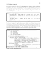
3.1.1 Modifying custom component settings
By opening the custom component editor I could define the custom component in the way
I wanted it to be. To open the custom component editor, first mark the custom component,
right-click and choose Edit Custom Component (see picture 4).
Picture 4. Opening the custom component editor.
The custom component editor shows all parts included in the custom component, the
custom component editor toolbar and the custom component browser. In picture 5, I show
what the custom component editor looks like.
Picture 5. Custom component editor, the beam as main part and the two
wall panels as reference parts.
To be able to define the length of the component profile, I had to bind the insertion points
to the component planes. By doing this, the profile´s nodes became the same as the
insertion points of the custom component. In other words, I can define the profile to be
placed between the given insertion points.
1. Select component planes from the drop-down list in the Custom component editor
toolbar (picture 6).
Picture 6. Custom component editor.
2. Mark the start point of the profile and right-click. Select ´bind to plane´ and choose
the XY-plane at the position of the chosen point (see picture 7). Interrupt the
command and repeat with end point.
Picture 7. Custom component editor, binding insertion points to component planes.
3. When the variables menu in the custom component editor toolbar is opened, rows
D1 and D2 have been added to component parameters.
To link the profile name to custom component name, add a new row and select
component name as value type (see picture 8).
Picture 8. Custom component editor, variables menu.
4. In the custom component browser, go to ´Component objects´ – ´Part´ – ´General
properties´. Right-click on ´Name´ and select ´Add equation´, then fill in P1_name
as equation (see picture 9). The part name is then bound to the custom component
name (Parameter1) and will automatically be linked to the name typed for the
component.
Picture 9. Custom component browser, link profile name.
After I have exited the custom component editor, the custom component is found in the
component catalog (ctrl + F). Search for the custom component name and the component is
shown in the catalog window (see picture 10).
Picture 10. Component catalog.
Open the custom component by double-clicking its icon. The custom component dialog
box did not by default have enough fields for the user to be able to fill in the required
information about the details (see picture 11). Then, new tabs and fields had to be added to
the dialog box.
Picture 11. Component dialog box, primary.
3.1.2 Editing of input file
In my case I needed to be able to fill in information about fasteners, sealings, insulations
and flashings. All of these materials had to have their own tab with fields to fill in, to be
able to give the required material information for each detail. In picture 12 I have shown a
short example of how the input file can be customized and picture 14 shows the
customized dialog box.
Picture 12. Screen shot from edited custom component dialog file.
The first row in picture 12 signifies that a new tab with the name ´Sealing´ is inserted and
its position is 61. The following text defines the actual dialog box under the ´Sealing´ tab.
At the beginning of the objects.inp file you can also find a detailed explanation of how the
text code is structured (see picture 13). This file uses the same coding system as in the
input files for custom components, but this one concerns all objects in the model.
Picture 13. Screen shot from Object.inp.
Picture 14. Customized Custom component dialog box.
Since the dialog box for each detail was going to have the same appearance, the same input
file could be used for all custom components. The only modifications that had to be made
to make the file work with other custom components was the file name itself and the
custom component name at the beginning of the text file. These two had to correspond to
the name of the created custom component.
As an example of the input files you can find the input file for custom component EW_-1
enclosed in appendix 1.
3.2
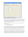
Loading of detail materials
To make the custom component easy to use, I pre-loaded all the details including their
materials and saved the details by their name. In this way, standard details became easy to
find in the drop-down list in the dialog box, and the user can in a few clicks select the
detail he wants to model. All fields in the dialog box were set as blank as default. This
makes it easy to type in new materials when a non-standard detail is used in a project.
When I started to pre-load the standard details, I began with details for wall panels with a
100 mm thickness. I consistently started from the first detail and typed its materials and
required information in the empty fields. When one detail was ready, I saved it by its name
and carried on with the next detail. Totally there were 230 details to be pre-loaded and
each of these had to be correctly defined so as not to give an incorrect output in the end.
When all the details had been saved, they could be loaded from the drop-down list in the
dialog box (see picture 15). When a detail is applied, all its information is included in the
custom component and the detail name is linked to the profile. As the profile name is the
same as detail name, it is easy to insert detail marks in general arrangement drawings by
using part marks. Detail marks are required for the site workers to know how each wall
panel will be fastened and which materials the connection includes.
Picture 15. Custom component dialog box, pre-loaded details for EW_-1.
3.3 Template editor
The template editor is a separate application included in Tekla Structures for editing
templates. The application can be run from Tekla Structures but also as a standalone
program. Templates can be used for defining text boxes included in drawings or for
creating reports from the model. The forms that the template editor describes can be either
in a graphical form for drawings or in an ASCII text form for reports. (Tekla Corporation
2009, p.3).
When creating a new textual template in the Template Editor, an empty page is inserted.
Template properties define size, margins and column usage of the template according to
the user´s own requirements. Headers, footers and rows can be added to the template and,
if necessary, rules can be added to these fields. (Tekla Corporation 2009, pp. 4-6).
In order to select information from the model, every row has to be given a certain content
type which can be read in the template. The content type defines what kind of data the row
will read from the model. In for example field formulas and rules, all programming is done
with the ordinary C programming language. (Tekla Corporation 2009, pp. 6-9).
3.3.1 Making of the template report
Since the final calculation and the material list were going to be made by a macro, the
appearance of this template report did not have any particular importance. The only
purpose of this template is to pick up detail materials, calculate them one by one and write
the results in a report. In consultation with Markus Vikström, we decided that all materials,
including their information and amounts, should be listed below each other as a simple list.
To facilitate the programming of the macro, different pieces of information about the
materials are separated with semicolons. Picture 16 shows a snapshot from the template
editor.
Picture 16. Template editor, finished template
The structure of this template is set so that the template selects the custom components one
by one and reads the fields in the dialog box. By using an if-statement, all empty fields are
left out while information defined in the fields will be written in the report. When all
details have been handled, the template finishes the calculations and creates the report.
Picture 17 shows an example of what the value field properties for picking up information
from sealing pieces look like.
Picture 17. Template editor, example of a value field for sealing pieces
4 Reflections and developments
At the beginning of my thesis work I had a hard time understanding how this application
would actually work. Thanks to Kennet Kurman´s thesis, Tekla´s extranet and Tekla
Structures´ help function I managed to create the application step by step. After I had
finished one step I had a wide understanding of what I had managed to create. While the
work with the application continued, I got more and more understanding of how the earlier
steps would affect the rest of the application. This resulted in constant changes made to the
earlier steps, to make the application more user-friendly, as the rest of the application work
proceeded.
One of the most challenging parts of my thesis work was to plan and customize the custom
component input file in such a way that it would be easy to understand and also easy to
make changes to. I also struggled with making the template report pick up the wanted
values from the custom components. The template editor training manual has been a real
gold mine offering extensive assistance in this matter.
The application turned out to be both effective and easy to use, which was the primary
intention of the application. By testing the application I found out that there are still some
modifications that would make the application even more effective. For example the
custom component type could be changed from seam to part. In this way, the reference
parts would not have to be selected and the insertion points of the detail would not have to
be as carefully picked as with seam (see user manual, Appendix 2). There might also be a
way to specify colors for the project only once and then directly link the colors to all
flashings according to their coating code.
As I mentioned in the foreword, the development work is ongoing and these changes are
going to be made as development work if they are found necessary. The application is
going to be used as a standard for the following projects and all users will be able to state
their opinion about the usage of this application. After a while we will decide if there is
something that has to be changed or not.
5 Sources
Kurman, K. (2008). Tekla structures wall detailing. Bachelor´s thesis. Svenska
Yrkeshögskolan, Technology and communications, Vaasa
Tekla Corporation.(2009). Template Editor. Training Manual, Product version 15.0
Tekla Corporation.(2012). Custom Components Guide. Product version 18.0
Tekla.(2012).
http://www.tekla.com/international
(Read 25.3.2012)
Citec.(2009).
http://www.citec.com/
(Read 25.3.2012)
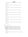
INPUT FILE FOR DETAIL EW_-1
page("TeklaStructures","")
{
joint(1, "EW_-1")
{
tab_page("", " Fasteners ", 60)
{
attribute("label", "Type", label, "%s", no, none, "0.0", "0.0", 30,0)
attribute("label", "Pcs.", label, "%s", no, none, "0.0", "0.0", 250, 0)
attribute("label", "c/c", label, "%s", no, none, "0.0", "0.0", 390, 0)
attribute("F1", "" , string, "%s", no, none, "0.0", "0.0", 30, 50 )
{
value("", 0)
}
attribute("F1pcs", "" , integer, "%d", no, none, "0.0", "0.0", 250, 50 )
{
value("", 0)
}
attribute("F1cc", "" , integer, "%d", no, none, "0.0", "0.0", 390, 50 )
{
value("", 0)
}
attribute("F2", "" , string, "%s", no, none, "0.0", "0.0", 30, 80 )
{
value("", 0)
}
attribute("F2pcs", "" , integer, "%d", no, none, "0.0", "0.0", 250, 80 )
{
value("", 0)
}
attribute("F2cc", "" , integer, "%d", no, none, "0.0", "0.0", 390, 80 )
{
value("", 0)
}
attribute("F3", "" , string, "%s", no, none, "0.0", "0.0", 30, 110 )
{
value("", 0)
}
attribute("F3pcs", "" , integer, "%d", no, none, "0.0", "0.0", 250, 110 )
{
value("", 0)
}
attribute("F3cc", "" , integer, "%d", no, none, "0.0", "0.0", 390, 110 )
{
value("", 0)
}
attribute("F4", "" , string, "%s", no, none, "0.0", "0.0", 30, 140 )
{
value("", 0)
}
attribute("F4pcs", "" , integer, "%d", no, none, "0.0", "0.0", 250, 140 )
{
value("", 0)
}
attribute("F4cc", "" , integer, "%d", no, none, "0.0", "0.0", 390, 140 )
{
value("", 0)
}
attribute("F5", "" , string, "%s", no, none, "0.0", "0.0", 30, 170 )
{
value("", 0)
}
attribute("F5pcs", "" , integer, "%d", no, none, "0.0", "0.0", 250, 170 )
{
value("", 0)
}
attribute("F5cc", "" , integer, "%d", no, none, "0.0", "0.0", 390, 170 )
{
value("", 0)
}
attribute("F6", "" , string, "%s", no, none, "0.0", "0.0", 30, 200 )
{
value("", 0)
}
attribute("F6pcs", "" , integer, "%d", no, none, "0.0", "0.0", 250, 200 )
{
value("", 0)
}
attribute("F6cc", "" , integer, "%d", no, none, "0.0", "0.0", 390, 200 )
{
value("", 0)
}
attribute("F7", "" , string, "%s", no, none, "0.0", "0.0", 30, 230 )
{
value("", 0)
}
attribute("F7pcs", "" , integer, "%d", no, none, "0.0", "0.0", 250, 230 )
{
value("", 0)
}
attribute("F7cc", "" , integer, "%d", no, none, "0.0", "0.0", 390, 230 )
{
value("", 0)
}
attribute("F8", "" , string, "%s", no, none, "0.0", "0.0", 30, 260 )
{
value("", 0)
}
attribute("F8pcs", "" , integer, "%d", no, none, "0.0", "0.0", 250, 260 )
{
value("", 0)
}
attribute("F8cc", "" , integer, "%d", no, none, "0.0", "0.0", 390, 260 )
{
value("", 0)
}
}
tab_page("", " Sealing ", 61)
{
attribute("label", "Type", label, "%s", no, none, "0.0", "0.0", 30,0)
attribute("label", "Pcs.", label, "%s", no, none, "0.0", "0.0", 250, 0)
attribute("S1", "", string, "%s", no, none, "0.0", "0.0", 30, 50)
{
value("", 0)
}
attribute("S1pcs", "", integer, "%d", no, none, "0.0", "0.0", 250, 50)
{
value("", 0)
}
attribute("S2", "", string, "%s", no, none, "0.0", "0.0", 30, 80)
{
value("", 0)
}
attribute("S2pcs", "" , integer, "%d", no, none, "0.0", "0.0", 250, 80)
{
value("", 0)
}
attribute("S3", "", string, "%s", no, none, "0.0", "0.0", 30, 110)
{
value("", 0)
}
attribute("S3pcs", "" , integer, "%d", no, none, "0.0", "0.0", 250, 110)
{
value("", 0)
}
attribute("S4", "", string, "%s", no, none, "0.0", "0.0", 30, 140)
{
value("", 0)
}
attribute("S4pcs", "", integer, "%d", no, none, "0.0", "0.0", 250, 140)
{
value("", 0)
}
attribute("S5", "", string, "%s", no, none, "0.0", "0.0", 30, 170)
{
value("", 0)
}
attribute("S5pcs", "", integer, "%d", no, none, "0.0", "0.0", 250, 170)
{
value("", 0)
}
attribute("S6", "", string, "%s", no, none, "0.0", "0.0", 30, 200)
{
value("", 0)
}
attribute("S6pcs", "", integer, "%d", no, none, "0.0", "0.0", 250, 200)
{
value("", 0)
}
attribute("S7", "", string, "%s", no, none, "0.0", "0.0", 30, 230)
{
value("", 0)
}
attribute("S7pcs", "", integer, "%d", no, none, "0.0", "0.0", 250, 230)
{
value("", 0)
}
attribute("S8", "", string, "%s", no, none, "0.0", "0.0", 30, 260)
{
value("", 0)
}
attribute("S8pcs", "", integer, "%d", no, none, "0.0", "0.0", 250, 260)
{
value("", 0)
}
}
tab_page("", " Insulation ", 62)
{
attribute("label", "Type", label, "%s", no, none, "0.0", "0.0", 30,0)
attribute("label", "Pcs.", label, "%s", no, none, "0.0", "0.0", 250, 0)
attribute("I1", "" , string, "%s", no, none, "0.0", "0.0", 30, 50, 100)
{
value("", 0)
}
attribute("I1pcs", "" , integer, "%d", no, none, "0.0", "0.0", 250, 50)
{
value("", 0)
}
attribute("I2", "" , string, "%s", no, none, "0.0", "0.0", 30, 80, 100)
{
value("", 0)
}
attribute("I2pcs", "" , integer, "%d", no, none, "0.0", "0.0", 250, 80)
{
value("", 0)
}
attribute("I3", "" , string, "%s", no, none, "0.0", "0.0", 30, 110, 100)
{
value("", 0)
}
attribute("I3pcs", "" , integer, "%d", no, none, "0.0", "0.0", 250, 110)
{
value("", 0)
}
attribute("I4", "" , string, "%s", no, none, "0.0", "0.0", 30, 140, 100)
{
value("", 0)
}
attribute("I4pcs", "" , integer, "%d", no, none, "0.0", "0.0", 250, 140)
{
value("", 0)
}
attribute("I5", "" , string, "%s", no, none, "0.0", "0.0", 30, 170, 100)
{
value("", 0)
}
attribute("I5pcs", "" , integer, "%d", no, none, "0.0", "0.0", 250, 170)
{
value("", 0)
}
attribute("I6", "" , string, "%s", no, none, "0.0", "0.0", 30, 200, 100)
{
value("", 0)
}
attribute("I6pcs", "" , integer, "%d", no, none, "0.0", "0.0", 250, 200)
{
value("", 0)
}
attribute("I7", "" , string, "%s", no, none, "0.0", "0.0", 30, 230, 100)
{
value("", 0)
}
attribute("I7pcs", "" , integer, "%d", no, none, "0.0", "0.0", 250, 230)
{
value("", 0)
}
attribute("I8", "" , string, "%s", no, none, "0.0", "0.0", 30, 260, 100)
{
value("", 0)
}
attribute("I8pcs", "" , integer, "%d", no, none, "0.0", "0.0", 250, 260)
{
value("", 0)
}
}
tab_page("", " Flashings ", 63)
{
attribute("label", "Type", label, "%s", no, none, "0.0", "0.0", 30, 0)
attribute("label", "Code", label, "%s", no, none, "0.0", "0.0", 160, 0)
attribute("label", "Pcs.", label, "%s", no, none, "0.0", "0.0", 270, 0)
attribute("label", "Coating", label, "%s", no, none, "0.0", "0.0", 390, 0)
attribute("label", "Color", label, "%s", no, none, "0.0", "0.0", 550, 0)
attribute("Fl1", "", string, "%s", no, none, "0.0", "0.0", 30, 50, 100)
{
value("", 0)
}
attribute("Fl1code", "" , integer, "%d", no, none, "0.0", "0.0", 160, 50, 50)
{
value("", 0)
}
attribute("Fl1pcs", "" , integer, "%d", no, none, "0.0", "0.0", 270, 50)
{
value("", 0)
}
attribute("Fl1coating", "" , string, "%s", no, none, "0.0", "0.0", 390, 50, 100)
{
value("", 0)
}
attribute("Fl1color", "" , string, "%s", no, none, "0.0", "0.0", 550, 50)
{
value("", 0)
}
attribute("Fl2", "" , string, "%s", no, none, "0.0", "0.0", 30, 80, 100)
{
value("", 0)
}
attribute("Fl2code", "" , integer, "%d", no, none, "0.0", "0.0", 160, 80, 50)
{
value("", 0)
}
attribute("Fl2pcs", "" , integer, "%d", no, none, "0.0", "0.0", 270, 80)
{
value("", 0)
}
attribute("Fl2coating", "" , string, "%s", no, none, "0.0", "0.0", 390, 80, 100)
{
value("", 0)
}
attribute("Fl2color", "" , string, "%s", no, none, "0.0", "0.0", 550, 80)
{
value("", 0)
}
attribute("Fl3", "" , string, "%s", no, none, "0.0", "0.0", 30, 110, 100)
{
value("", 0)
}
attribute("Fl3code", "" , integer, "%d", no, none, "0.0", "0.0", 160, 110, 50)
{
value("", 0)
}
attribute("Fl3pcs", "" , integer, "%d", no, none, "0.0", "0.0", 270, 110)
{
value("", 0)
}
attribute("Fl3coating", "" , string, "%s", no, none, "0.0", "0.0", 390, 110, 100)
{
value("", 0)
}
attribute("Fl3color", "" , string, "%s", no, none, "0.0", "0.0", 550, 110)
{
value("", 0)
}
attribute("Fl4", "" , string, "%s", no, none, "0.0", "0.0", 30, 140, 100)
{
value("", 0)
}
attribute("Fl4code", "" , integer, "%d", no, none, "0.0", "0.0", 160, 140, 50)
{
value("", 0)
}
attribute("Fl4pcs", "" , integer, "%d", no, none, "0.0", "0.0", 270, 140)
{
value("", 0)
}
attribute("Fl4coating", "" , string, "%s", no, none, "0.0", "0.0", 390, 140, 100)
{
value("", 0)
}
attribute("Fl4color", "" , string, "%s", no, none, "0.0", "0.0", 550, 140)
{
value("", 0)
}
attribute("Fl5", "" , string, "%s", no, none, "0.0", "0.0", 30, 170, 100)
{
value("", 0)
}
attribute("Fl5code", "" , integer, "%d", no, none, "0.0", "0.0", 160, 170, 50)
{
value("", 0)
}
attribute("Fl5pcs", "" , integer, "%d", no, none, "0.0", "0.0", 270, 170)
{
value("", 0)
}
attribute("Fl5coating", "" , string, "%s", no, none, "0.0", "0.0", 390, 170, 100)
{
value("", 0)
}
attribute("Fl5color", "" , string, "%s", no, none, "0.0", "0.0", 550, 170)
{
value("", 0)
}
attribute("Fl6", "" , string, "%s", no, none, "0.0", "0.0", 30, 200, 100)
{
value("", 0)
}
attribute("Fl6code", "" , integer, "%d", no, none, "0.0", "0.0", 160, 200, 50)
{
value("", 0)
}
attribute("Fl6pcs", "" , integer, "%d", no, none, "0.0", "0.0", 270, 200)
{
value("", 0)
}
attribute("Fl6coating", "" , string, "%s", no, none, "0.0", "0.0", 390, 200, 100)
{
value("", 0)
}
attribute("Fl6color", "" , string, "%s", no, none, "0.0", "0.0", 550, 200)
{
value("", 0)
}
attribute("Fl7", "" , string, "%s", no, none, "0.0", "0.0", 30, 230, 100)
{
value("", 0)
}
attribute("Fl7code", "" , integer, "%d", no, none, "0.0", "0.0", 160, 230, 50)
{
value("", 0)
}
attribute("Fl7pcs", "" , integer, "%d", no, none, "0.0", "0.0", 270, 230)
{
value("", 0)
}
attribute("Fl7coating", "" , string, "%s", no, none, "0.0", "0.0", 390, 230, 100)
{
value("", 0)
}
attribute("Fl7color", "" , string, "%s", no, none, "0.0", "0.0", 550, 230)
{
value("", 0)
}
attribute("Fl8", "" , string, "%s", no, none, "0.0", "0.0", 30, 260, 100)
{
value("", 0)
}
attribute("Fl8code", "" , integer, "%d", no, none, "0.0", "0.0", 160, 260, 50)
{
value("", 0)
}
attribute("Fl8pcs", "" , integer, "%d", no, none, "0.0", "0.0", 270, 260)
{
value("", 0)
}
attribute("Fl8coating", "" , string, "%s", no, none, "0.0", "0.0", 390, 260, 100)
{
value("", 0)
}
attribute("Fl8color", "" , string, "%s", no, none, "0.0", "0.0", 550, 260)
{
value("", 0)
}
}
tab_page("", " Detail Information ", 59)
{
attribute("label", "Name", label, "%s", no, none, "0.0", "0.0", 30, 0)
attribute("label", "Contents", label, "%s", no, none, "0.0", "0.0", 250, 0)
parameter("Parameter1", "P1_name", string, text, 30, 50)
attribute("C", "" , string, "%d", no, none, "0.0", "0.0", 250, 50, 300)
{
value("", 0)
}
}
tab_page("", " Flashing Information ", 64)
{
attribute("label", "Length (mm)", label, "%s", no, none, "0.0", "0.0", 30, 0)
attribute("label", "Bends (pcs)", label, "%s", no, none, "0.0", "0.0", 230, 0)
attribute("label", "Width (mm)", label, "%s", no, none, "0.0", "0.0", 430, 0)
attribute("label", "Thickness (mm)", label, "%s", no, none, "0.0", "0.0", 630, 0)
attribute("Fl1length", "" , integer, "%s", no, none, "0.0", "0.0", 30, 50)
{
value("", 0)
}
attribute("Fl1bends", "" , integer, "%d", no, none, "0.0", "0.0", 230, 50)
{
value("", 0)
}
attribute("Fl1width", "" , integer, "%d", no, none, "0.0", "0.0", 430, 50)
{
value("", 0)
}
attribute("Fl1thickness", "" , float, "%d", no, none, "0.0", "0.0", 630, 50)
{
value("", 0)
}
attribute("Fl2length", "" , integer, "%s", no, none, "0.0", "0.0", 30, 80)
{
value("", 0)
}
attribute("Fl2bends", "" , integer, "%d", no, none, "0.0", "0.0", 230, 80)
{
value("", 0)
}
attribute("Fl2width", "" , integer, "%d", no, none, "0.0", "0.0", 430, 80)
{
value("", 0)
}
attribute("Fl2thickness", "" , float, "%d", no, none, "0.0", "0.0", 630, 80)
{
value("", 0)
}
attribute("Fl3length", "" , integer, "%s", no, none, "0.0", "0.0", 30, 110)
{
value("", 0)
}
attribute("Fl3bends", "" , integer, "%d", no, none, "0.0", "0.0", 230, 110)
{
value("", 0)
}
attribute("Fl3width", "" , integer, "%d", no, none, "0.0", "0.0", 430, 110)
{
value("", 0)
}
attribute("Fl3thickness", "" , float, "%d", no, none, "0.0", "0.0", 630, 110)
{
value("", 0)
}
attribute("Fl4length", "" , integer, "%s", no, none, "0.0", "0.0", 30, 140)
{
value("", 0)
}
attribute("Fl4bends", "" , integer, "%d", no, none, "0.0", "0.0", 230, 140)
{
value("", 0)
}
attribute("Fl4width", "" , integer, "%d", no, none, "0.0", "0.0", 430, 140)
{
value("", 0)
}
attribute("Fl4thickness", "" , float, "%d", no, none, "0.0", "0.0", 630, 140)
{
value("", 0)
}
attribute("Fl5length", "" , integer, "%s", no, none, "0.0", "0.0", 30, 170)
{
value("", 0)
}
attribute("Fl5bends", "" , integer, "%d", no, none, "0.0", "0.0", 230, 170)
{
value("", 0)
}
attribute("Fl5width", "" , integer, "%d", no, none, "0.0", "0.0", 430, 170)
{
value("", 0)
}
attribute("Fl5thickness", "" , float, "%d", no, none, "0.0", "0.0", 630, 170)
{
value("", 0)
}
attribute("Fl6length", "" , integer, "%s", no, none, "0.0", "0.0", 30, 200)
{
value("", 0)
}
attribute("Fl6bends", "" , integer, "%d", no, none, "0.0", "0.0", 230, 200)
{
value("", 0)
}
attribute("Fl6width", "" , integer, "%d", no, none, "0.0", "0.0", 430, 200)
{
value("", 0)
}
attribute("Fl6thickness", "" , float, "%d", no, none, "0.0", "0.0", 630, 200)
{
value("", 0)
}
attribute("Fl7length", "" , integer, "%s", no, none, "0.0", "0.0", 30, 230)
{
value("", 0)
}
attribute("Fl7bends", "" , integer, "%d", no, none, "0.0", "0.0", 230, 230)
{
value("", 0)
}
attribute("Fl7width", "" , integer, "%d", no, none, "0.0", "0.0", 430, 230)
{
value("", 0)
}
attribute("Fl7thickness", "" , float, "%d", no, none, "0.0", "0.0", 630, 230)
{
value("", 0)
}
attribute("Fl8length", "" , integer, "%s", no, none, "0.0", "0.0", 30, 260)
{
value("", 0)
}
attribute("Fl8bends", "" , integer, "%d", no, none, "0.0", "0.0", 230, 260)
{
value("", 0)
}
attribute("Fl8width", "" , integer, "%d", no, none, "0.0", "0.0", 430, 260)
{
value("", 0)
}
attribute("Fl8thickness", "" , float, "%d", no, none, "0.0", "0.0", 630, 260)
{
value("", 0)
}
}
}
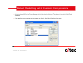
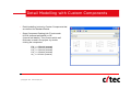
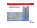
DETAIL MODELLING WITH CUSTOM COMPONENTS
Detail Modelling
with Custom Components
Detail Modelling with Custom Components
•
Activate phase 4005 in the Phase Manager (ctrl+H) by double klicking it. The phase is included in Wall Panel
Template.
•
If the details are not modelled on this phase, the filter for Wall Panel Details will not work.
© Copyright 2011 Citec Group Oy Ab
Detail Modelling with Custom Components
•
Detail modelling is done by Costum Components that
are defined for Standard Details.
•
Open Component Catalog (ctrl+F) and search
for EW (external wall details) or IW
(internal wall details). Then choose which wall
thickness is used in the project by double
clicking the component.
EW_-1 = SPA100 (external)
EW_-2 = SPA125 (external)
EW_-3 = SPA150 (external)
EW_-4 = SPA200 (external)
IW_-1 = SPA100 (internal)
© Copyright 2011 Citec Group Oy Ab
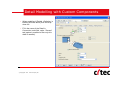
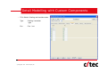
Detail Modelling with Custom Components
•
Choose from the drop-down list which detail is
going to be used and press ´Load´.
•
Go to ´Flashings´ tab and fill in color of the
flashings, then press Modify and Apply.
© Copyright 2011 Citec Group Oy Ab
Detail Modelling with Custom Components
•
When modelling X-Details <Defaults> is
loaded (all boxes blank) from the dropdown list.
•
Fill in the name of the Detail in
Connection code field, under ´General´
tab (makes it possible to filter only this
detail if needed).
© Copyright 2011 Citec Group Oy Ab
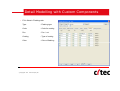
Detail Modelling with Custom Components
•
Fill in fields in Detail Information tab:
Name
- Detail Name
Contents
- Detail explanation
© Copyright 2011 Citec Group Oy Ab
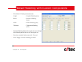
Detail Modelling with Custom Components
•
Fill in fields in Fasteners tab:
Type
- Fastener type
Pcs.
- Pcs. / cut
c/c
- Distance between
fasteners (mm)
© Copyright 2011 Citec Group Oy Ab
Detail Modelling with Custom Components
•
Fill in fields in Sealing and Insulation tabs:
Type
- Sealing / Insulation
type
Pcs.
- Pcs. / cut
© Copyright 2011 Citec Group Oy Ab
Detail Modelling with Custom Components
•
Fill in fields in Flashings tab:
Type
- Flashing type
Code
- Code for coating
Pcs.
- Pcs. / cut
Coating
- Type of coating
Color
- Color of flashing
© Copyright 2011 Citec Group Oy Ab
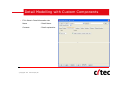
Detail Modelling with Custom Components
•
Fill in fields in Flashing Information tab:
Length
- Length of flashing (mm)
Bends
- Number of flashing
bends
Width
- Width of flashing (mm)
Thickness
- Thickness of flashing
(mm)
•
Note that Flashing Information at the first row, belongs
to the flashing at the first row at Flashing tab etc.
•
Save the new detail by its name with ´Save as´.
•
Press ´Apply´ and start modelling the detail.
© Copyright 2011 Citec Group Oy Ab
Detail Modelling with Custom Components
•
When Connection is activated, choose two
reference parts (doesn´t matter which ones)
•
Then pick start and end position of the detail. The
position of the detail should be in the center of the
wall panels.
•
The detail is now in place and all its materials
specified with it.
© Copyright 2011 Citec Group Oy Ab
Detail Modelling with Custom Components
•
If the length of the detail need to be changed, just
mark start or end point and move it (doesn´t
matter if the connection cone moves or not, since
materials are bond to the actual parts´ length).
•
If the connection fails, the details´ insertion points
are likely slightly oblique. Then remove the
connection and redo it. Make sure that insertion
points are in line.
© Copyright 2011 Citec Group Oy Ab
Detail Modelling with Custom Components
•
When creating general arrangement drawings, using WFI_Panel_layout or
Ruukki_Penel_layout settings, the detail marks appear automatically in the
drawings.
© Copyright 2011 Citec Group Oy Ab
Detail Modelling with Custom Components
•
Originally, the detail marks can only be
moved along the modelled component part,
but changing the Leader line type in the Part
mark Properties, allows to freely move the
detail mark.
© Copyright 2011 Citec Group Oy Ab
•
Also the font height of the detail marks can be
changed where needed, to get a better look of
the drawing.
Detail Modelling with Custom Components
•
When all the details are in place, it´s time to make the material
report.
•
Choose the ´Wall_Panel_Details´ filter to get only details visible.
•
Make sure you have ´Select components´ from selecting field
activated, then mark all the details.
© Copyright 2011 Citec Group Oy Ab
•
Go to ´Tools´ – ´Macros´ and choose
´Wall_Detail_Material_List´, then press
´Run´.
Detail Modelling with Custom Components
•
This macro is doing the actual calculation for the materials
and writes the result to a report. All materials are calculated
with included spillage.
•
The Material List (in excel format) is saved in ´Reports´ folder
with the name ´Wall_Detail_Material_List.csv´.
•
Simply copy all the flashing data from the material list and paste it to
´LIST OF FLASHINGS (for macro).xls´. Amounts of Wall Panel
Accessories are inserted to the ´ WALL PANEL ACCESSORIES.xls´
list.
© Copyright 2011 Citec Group Oy Ab
Detail Modelling with Custom Components
NOTE!
•
When copying a Custom Component, be sure that Component Cone is
selected! Otherwise only the part is copied and the material data will be
lost.
•
The components of EW9-_00 & EW9-_01 should be modelled with the
length of 425mm.
•
The components of EW9-_02 & EW9-_03 should be modelled with the
length of 592mm.
•
The components of EW4-_05 & EW5-_06 should be modelled with the
length of 1000mm.
© Copyright 2011 Citec Group Oy Ab
Detail Modelling with Custom Components
NOTE!
•
When modeling details between EH and UB, including both walls, the
details are only inserted on one side (either in EH or UB). Else the
material amount will be the double.
•
To get detail marks to the drawing where a detail is not inserted, detail
marks has to be manually inserted.
•
This regards following details:
© Copyright 2011 Citec Group Oy Ab
IW4-105
IW4-115
IW6-102
IW6-104